1
P
MOTION CONTROLLER Qseries
Programming Manual (COMMON)
(Q173HCPU/Q172HCPU)
MOTION CONTROLLERS
MOTION CONTROLLER Qseries Programming Manual (COMMON) (Q173HCPU/Q172HCPU)
COMMON
Q173HCPU
Q172HCPU
HEAD OFFICE : 1-8-12, OFFICE TOWER Z 14F HARUMI CHUO-KU 104-6212,JAPAN
NAGOYA WORKS : 1-14 , YADA-MINAMI 5-CHOME , HIGASHI-KU, NAGOYA , JAPAN
MODEL
Q173H-P-COM-E
MODEL
CODE
1XB911
IB(NA)-0300111-A(0506)MEE
IB(NA)-0300111-A(0506)MEE
Programming Manual
When exported from Japan, this manual does not require application to the
Ministry of Economy, Trade and Industry for service transaction permission.
Specifications subject to change without notice.
Q
SAFETY PRECAUTIONS
(Read these precautions before using.)
When using this equipment, thoroughly read this manual and the associated manuals introduced in this
manual. Also pay careful attention to safety and handle the module properly.
These precautions apply only to this equipment. Refer to the Q173HCPU/Q172HCPU Users manual for a
description of the Motion controller safety precautions.
These SAFETY PRECAUTIONS classify the safety precautions into two categories: "DANGER" and
"CAUTION".
DANGER
Indicates that incorrect handling may cause hazardous conditions,
resulting in death or severe injury.
! CAUTION
Indicates that incorrect handling may cause hazardous conditions,
resulting in medium or slight personal injury or physical damage.
!
Depending on circumstances, procedures indicated by ! CAUTION may also be linked to serious
results.
In any case, it is important to follow the directions for usage.
Store this manual in a safe place so that you can take it out and read it whenever necessary. Always
forward it to the end user.
A-1
For Safe Operations
1. Prevention of electric shocks
DANGER
!
Never open the front case or terminal covers while the power is ON or the unit is running, as this
may lead to electric shocks.
Never run the unit with the front case or terminal cover removed. The high voltage terminal and
charged sections will be exposed and may lead to electric shocks.
Never open the front case or terminal cover at times other than wiring work or periodic
inspections even if the power is OFF. The insides of the Motion controller and servo amplifier are
charged and may lead to electric shocks.
When performing wiring work or inspections, turn the power OFF, wait at least ten minutes, and
then check the voltage with a tester, etc.. Failing to do so may lead to electric shocks.
Be sure to ground the Motion controller, servo amplifier and servomotor. (Ground resistance :
100 or less) Do not ground commonly with other devices.
The wiring work and inspections must be done by a qualified technician.
Wire the units after installing the Motion controller, servo amplifier and servomotor. Failing to do
so may lead to electric shocks or damage.
Never operate the switches with wet hands, as this may lead to electric shocks.
Do not damage, apply excessive stress, place heavy things on or sandwich the cables, as this
may lead to electric shocks.
Do not touch the Motion controller, servo amplifier or servomotor terminal blocks while the power
is ON, as this may lead to electric shocks.
Do not touch the built-in power supply, built-in grounding or signal wires of the Motion controller
and servo amplifier, as this may lead to electric shocks.
2. For fire prevention
!
CAUTION
Install the Motion controller, servo amplifier, servomotor and regenerative resistor on inflammable
material. Direct installation on flammable material or near flammable material may lead to fire.
If a fault occurs in the Motion controller or servo amplifier, shut the power OFF at the servo
amplifier’s power source. If a large current continues to flow, fire may occur.
When using a regenerative resistor, shut the power OFF with an error signal. The regenerative
resistor may abnormally overheat due to a fault in the regenerative transistor, etc., and may lead
to fire.
Always take heat measures such as flame proofing for the inside of the control panel where the
servo amplifier or regenerative resistor is installed and for the wires used. Failing to do so may
lead to fire.
A-2
3. For injury prevention
!
CAUTION
Do not apply a voltage other than that specified in the instruction manual on any terminal.
Doing so may lead to destruction or damage.
Do not mistake the terminal connections, as this may lead to destruction or damage.
Do not mistake the polarity ( + / - ), as this may lead to destruction or damage.
Do not touch the servo amplifier's heat radiating fins, regenerative resistor and servomotor, etc.,
while the power is ON and for a short time after the power is turned OFF. In this timing, these
parts become very hot and may lead to burns.
Always turn the power OFF before touching the servomotor shaft or coupled machines, as these
parts may lead to injuries.
Do not go near the machine during test operations or during operations such as teaching.
Doing so may lead to injuries.
4. Various precautions
Strictly observe the following precautions.
Mistaken handling of the unit may lead to faults, injuries or electric shocks.
(1) System structure
!
CAUTION
Always install a leakage breaker on the Motion controller and servo amplifier power source.
If installation of an electromagnetic contactor for power shut off during an error, etc., is specified in
the instruction manual for the servo amplifier, etc., always install the electromagnetic contactor.
Install the emergency stop circuit externally so that the operation can be stopped immediately and
the power shut off.
Use the Motion controller, servo amplifier, servomotor and regenerative resistor with the combinations listed in the instruction manual. Other combinations may lead to fire or faults.
If safety standards (ex., robot safety rules, etc.,) apply to the system using the Motion controller,
servo amplifier and servomotor, make sure that the safety standards are satisfied.
Construct a safety circuit externally of the Motion controller or servo amplifier if the abnormal
operation of the Motion controller or servo amplifier differ from the safety directive operation in the
system.
In systems where coasting of the servomotor will be a problem during the forced stop, emergency
stop, servo OFF or power supply OFF, use dynamic brakes.
Make sure that the system considers the coasting amount even when using dynamic brakes.
In systems where perpendicular shaft dropping may be a problem during the forced stop,
emergency stop, servo OFF or power supply OFF, use both dynamic brakes and electromagnetic
brakes.
The dynamic brakes must be used only on errors that cause the forced stop, emergency stop, or
servo OFF. These brakes must not be used for normal braking.
A-3
!
CAUTION
The brakes (electromagnetic brakes) assembled into the servomotor are for holding applications,
and must not be used for normal braking.
The system must have a mechanical allowance so that the machine itself can stop even if the
stroke limits switch is passed through at the max. speed.
Use wires and cables that have a wire diameter, heat resistance and bending resistance
compatible with the system.
Use wires and cables within the length of the range described in the instruction manual.
The ratings and characteristics of the parts (other than Motion controller, servo amplifier and
servomotor) used in a system must be compatible with the Motion controller, servo amplifier and
servomotor.
Install a cover on the shaft so that the rotary parts of the servomotor are not touched during
operation.
There may be some cases where holding by the electromagnetic brakes is not possible due to the
life or mechanical structure (when the ball screw and servomotor are connected with a timing belt,
etc.). Install a stopping device to ensure safety on the machine side.
(2) Parameter settings and programming
!
CAUTION
Set the parameter values to those that are compatible with the Motion controller, servo amplifier,
servomotor and regenerative resistor model and the system application. The protective functions
may not function if the settings are incorrect.
The regenerative resistor model and capacity parameters must be set to values that conform to
the operation mode, servo amplifier and servo power supply module. The protective functions
may not function if the settings are incorrect.
Set the mechanical brake output and dynamic brake output validity parameters to values that are
compatible with the system application. The protective functions may not function if the settings
are incorrect.
Set the stroke limit input validity parameter to a value that is compatible with the system
application. The protective functions may not function if the setting is incorrect.
Set the servomotor encoder type (increment, absolute position type, etc.) parameter to a value
that is compatible with the system application. The protective functions may not function if the
setting is incorrect.
Set the servomotor capacity and type (standard, low-inertia, flat, etc.) parameter to values that
are compatible with the system application. The protective functions may not function if the
settings are incorrect.
Set the servo amplifier capacity and type parameters to values that are compatible with the
system application. The protective functions may not function if the settings are incorrect.
Use the program commands for the program with the conditions specified in the instruction
manual.
A-4
!
CAUTION
Set the sequence function program capacity setting, device capacity, latch validity range, I/O
assignment setting, and validity of continuous operation during error detection to values that are
compatible with the system application. The protective functions may not function if the settings
are incorrect.
Some devices used in the program have fixed applications, so use these with the conditions
specified in the instruction manual.
The input devices and data registers assigned to the link will hold the data previous to when
communication is terminated by an error, etc. Thus, an error correspondence interlock program
specified in the instruction manual must be used.
Use the interlock program specified in the special function module's instruction manual for the
program corresponding to the special function module.
(3) Transportation and installation
!
CAUTION
Transport the product with the correct method according to the mass.
Use the servomotor suspension bolts only for the transportation of the servomotor. Do not
transport the servomotor with machine installed on it.
Do not stack products past the limit.
When transporting the Motion controller or servo amplifier, never hold the connected wires or
cables.
When transporting the servomotor, never hold the cables, shaft or detector.
When transporting the Motion controller or servo amplifier, never hold the front case as it may fall
off.
When transporting, installing or removing the Motion controller or servo amplifier, never hold the
edges.
Install the unit according to the instruction manual in a place where the mass can be withstood.
Do not get on or place heavy objects on the product.
Always observe the installation direction.
Keep the designated clearance between the Motion controller or servo amplifier and control panel
inner surface or the Motion controller and servo amplifier, Motion controller or servo amplifier and
other devices.
Do not install or operate Motion controller, servo amplifiers or servomotors that are damaged or
that have missing parts.
Do not block the intake/outtake ports of the servomotor with cooling fan.
Do not allow conductive matter such as screw or cutting chips or combustible matter such as oil
enter the Motion controller, servo amplifier or servomotor.
The Motion controller, servo amplifier and servomotor are precision machines, so do not drop or
apply strong impacts on them.
A-5
!
CAUTION
Securely fix the Motion controller and servo amplifier to the machine according to the instruction
manual. If the fixing is insufficient, these may come off during operation.
Always install the servomotor with reduction gears in the designated direction. Failing to do so
may lead to oil leaks.
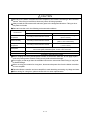
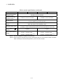
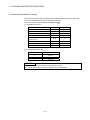
Store and use the unit in the following environmental conditions.
Environment
Ambient
temperature
Ambient humidity
Storage
temperature
Atmosphere
Altitude
Vibration
Conditions
Motion controller/Servo amplifier
According to each instruction manual.
According to each instruction manual.
According to each instruction manual.
Servomotor
0°C to +40°C (With no freezing)
(32°F to +104°F)
80% RH or less
(With no dew condensation)
-20°C to +65°C
(-4°F to +149°F)
Indoors (where not subject to direct sunlight).
No corrosive gases, flammable gases, oil mist or dust must exist
1000m (3280.84ft.) or less above sea level
According to each instruction manual
When coupling with the synchronization encoder or servomotor shaft end, do not apply impact
such as by hitting with a hammer. Doing so may lead to detector damage.
Do not apply a load larger than the tolerable load onto the servomotor shaft. Doing so may lead
to shaft breakage.
When not using the module for a long time, disconnect the power line from the Motion controller
or servo amplifier.
Place the Motion controller and servo amplifier in static electricity preventing vinyl bags and store.
When storing for a long time, please contact with our sales representative.
A-6
(4) Wiring
!
CAUTION
Correctly and securely wire the wires. Reconfirm the connections for mistakes and the terminal
screws for tightness after wiring. Failing to do so may lead to run away of the
servomotor.
After wiring, install the protective covers such as the terminal covers to the original positions.
Do not install a phase advancing capacitor, surge absorber or radio noise filter (option FR-BIF)
on the output side of the servo amplifier.
Correctly connect the output side (terminals U, V, W). Incorrect connections will lead the
servomotor to operate abnormally.
Do not connect a commercial power supply to the servomotor, as this may lead to trouble.
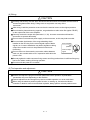
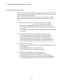
Do not mistake the direction of the surge absorbing diode
Servo amplifier
installed on the DC relay for the control signal output of brake
VIN
signals, etc. Incorrect installation may lead to signals not being
(24VDC)
output when trouble occurs or the protective functions not
functioning.
Control output
RA
signal
Do not connect or disconnect the connection cables between
each unit, the encoder cable or PLC expansion cable while the
power is ON.
Securely tighten the cable connector fixing screws and fixing mechanisms. Insufficient fixing may
lead to the cables combing off during operation.
Do not bundle the power line or cables.
(5) Trial operation and adjustment
!
CAUTION
Confirm and adjust the program and each parameter before operation. Unpredictable
movements may occur depending on the machine.
Extreme adjustments and changes may lead to unstable operation, so never make them.
When using the absolute position system function, on starting up, and when the Motion
controller or absolute value motor has been replaced, always perform a home position return.
A-7
(6) Usage methods
!
CAUTION
Immediately turn OFF the power if smoke, abnormal sounds or odors are emitted from the Motion
controller, servo amplifier or servomotor.
Always execute a test operation before starting actual operations after the program or
parameters have been changed or after maintenance and inspection.
The units must be disassembled and repaired by a qualified technician.
Do not make any modifications to the unit.
Keep the effect or electromagnetic obstacles to a minimum by installing a noise filter or by using
wire shields, etc. Electromagnetic obstacles may affect the electronic devices used near the
Motion controller or servo amplifier.
When using the CE Mark-compliant equipment, refer to the "EMC Installation Guidelines" (data
number IB(NA)-67339) for the Motion controllers and refer to the corresponding EMC guideline
information for the servo amplifiers, inverters and other equipment.
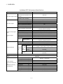
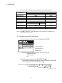
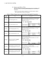
Use the units with the following conditions.
Item
Conditions
Q61P-A1
100 to 120VAC
Q61P-A2
+10%
-15%
200 to 240VAC
Q61P
+10%
-15%
Q62P
100 to 240VAC
+10%
-15%
Q63P
24VDC
Q64P
+30%
-35%
100 to 120VAC
200 to 240VAC
Input power
(85 to 132VAC)
(170 to 264VAC)
(85 to 264VAC)
Input frequency
50/60Hz ±5%
Tolerable
momentary
power failure
20ms or less
(15.6 to 31.2VDC)
+10%
-15%
+10%
-15%
(85 to 132VAC/
170 to 264VAC)
(7) Corrective actions for errors
!
CAUTION
If an error occurs in the self diagnosis of the Motion controller or servo amplifier, confirm the
check details according to the instruction manual, and restore the operation.
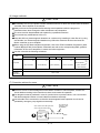
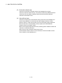
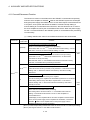
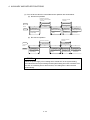
If a dangerous state is predicted in case of a power failure or product failure, use a servomotor
with electromagnetic brakes or install a brake mechanism externally.
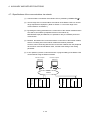
Use a double circuit construction so that the electromagnetic brake operation circuit can be
operated by emergency stop signals set externally.
Shut off with servo ON signal OFF,
alarm, magnetic brake signal.
Servomotor
RA1
Electromagnetic
brakes
Shut off with the
emergency stop
signal(EMG).
EMG
24VDC
A-8
/
!
CAUTION
If an error occurs, remove the cause, secure the safety and then resume operation after alarm
release.
The unit may suddenly resume operation after a power failure is restored, so do not go near the
machine. (Design the machine so that personal safety can be ensured even if the machine
restarts suddenly.)
(8) Maintenance, inspection and part replacement
!
CAUTION
Perform the daily and periodic inspections according to the instruction manual.
Perform maintenance and inspection after backing up the program and parameters for the Motion
controller and servo amplifier.
Do not place fingers or hands in the clearance when opening or closing any opening.
Periodically replace consumable parts such as batteries according to the instruction manual.
Do not touch the lead sections such as ICs or the connector contacts.
Do not place the Motion controller or servo amplifier on metal that may cause a power leakage or
wood, plastic or vinyl that may cause static electricity buildup.
Do not perform a megger test (insulation resistance measurement) during inspection.
When replacing the Motion controller or servo amplifier, always set the new module settings
correctly.
When the Motion controller or absolute value motor has been replaced, carry out a home position
return operation using one of the following methods, otherwise position displacement could occur.
1) After writing the servo data to the Motion controller using programming software, switch on the
power again, then perform a home position return operation.
2) Using the backup function of the programming software, load the data backed up before
replacement.
After maintenance and inspections are completed, confirm that the position detection of the
absolute position detector function is correct.
Do not short circuit, charge, overheat, incinerate or disassemble the batteries.
The electrolytic capacitor will generate gas during a fault, so do not place your face near the
Motion controller or servo amplifier.
The electrolytic capacitor and fan will deteriorate. Periodically replace these to prevent secondary
damage from faults. Replacements can be made by our sales representative.
A-9
(9) About processing of waste
When you discard Motion controller, servo amplifier, a battery (primary battery) and other option articles,
please follow the law of each country (area).
!
CAUTION
This product is not designed or manufactured to be used in equipment or systems in situations
that can affect or endanger human life.
When considering this product for operation in special applications such as machinery or systems
used in passenger transportation, medical, aerospace, atomic power, electric power, or
submarine repeating applications, please contact your nearest Mitsubishi sales representative.
Although this product was manufactured under conditions of strict quality control, you are strongly
advised to install safety devices to forestall serious accidents when it is used in facilities where a
breakdown in the product is likely to cause a serious accident.
(10) General cautions
!
CAUTION
All drawings provided in the instruction manual show the state with the covers and safety
partitions removed to explain detailed sections. When operating the product, always return the
covers and partitions to the designated positions, and operate according to the instruction manual.
A - 10
REVISIONS
The manual number is given on the bottom left of the back cover.
Print Date
Jun., 2005
May., 2006
Sep., 2006
Manual Number
Revision
IB(NA)-0300111-A First edition
IB(NA)-0300111-B [Additional model]
Software for SV43
[Additional correction/partial correction]
About Manuals
IB(NA)-0300111-C [Additional model]
Q61P, MR-J3- B(Large capacity), MR-J3- B-RJ006
[Additional correction/partial correction]
About Manuals, Servo parameters
Japanese Manual Number IB(NA)-0300091
This manual confers no industrial property rights or any rights of any other kind, nor does it confer any patent
licenses. Mitsubishi Electric Corporation cannot be held responsible for any problems involving industrial property
rights which may occur as a result of using the contents noted in this manual.
© 2005 MITSUBISHI ELECTRIC CORPORATION
A - 11
INTRODUCTION
Thank you for choosing the Q173HCPU/Q172HCPU Motion Controller.
Please read this manual carefully so that equipment is used to its optimum.
CONTENTS
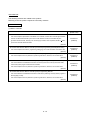
Safety Precautions .........................................................................................................................................A- 1
Revisions ........................................................................................................................................................A-11
Contents .........................................................................................................................................................A-12
About Manuals ...............................................................................................................................................A-15
1. OVERVIEW
1- 1 to 1-20
1.1 Overview................................................................................................................................................... 1- 1
1.2 Features ................................................................................................................................................... 1- 3
1.2.1 Features of Motion CPU ................................................................................................................... 1- 3
1.2.2 Basic specifications of Q173HCPU/Q172HCPU ............................................................................. 1- 5
1.3 Hardware Configuration ........................................................................................................................... 1-10
1.3.1 Motion system configuration ............................................................................................................. 1-10
1.3.2 Q173HCPU System overall configuration ........................................................................................ 1-12
1.3.3 Q172HCPU System overall configuration ........................................................................................ 1-14
1.3.4 Software packages............................................................................................................................ 1-16
1.3.5 Restrictions on motion systems........................................................................................................ 1-19
2. MULTIPLE CPU SYSTEM
2- 1 to 2-50
2.1 Multiple CPU System ............................................................................................................................... 2- 1
2.1.1 Overview............................................................................................................................................ 2- 1
2.1.2 Installation of PLC CPU and Motion CPU ........................................................................................ 2- 2
2.1.3 Precautions for using Q series I/O modules and intelligent function modules................................ 2- 3
2.1.4 Modules subject to installation restrictions ....................................................................................... 2- 4
2.1.5 Processing time of the Multiple CPU system ................................................................................... 2- 6
2.1.6 How to reset the Multiple CPU system............................................................................................. 2- 7
2.1.7 Processing at a CPU DOWN error occurrence by a PLC CPU or Q173HCPU/Q172HCPU......... 2- 8
2.2 Starting Up the Multiple CPU System ..................................................................................................... 2-11
2.2.1 Startup Flow of the Multiple CPU System ........................................................................................ 2-11
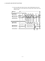
2.3 Communication between the PLC CPU and the Motion CPU in the Multiple CPU System ................. 2-13
2.3.1 Automatic Refresh Function of The Shared CPU Memory.............................................................. 2-13
2.3.2 Control Instruction from the PLC CPU to The Motion CPU (Motion dedicated instructions) ......... 2-39
2.3.3 Reading/Writing Device Data............................................................................................................ 2-40
2.3.4 Shared CPU Memory........................................................................................................................ 2-41
2.4 Multiple CPU Error Codes ....................................................................................................................... 2-45
2.4.1 Self-diagnosis error code .................................................................................................................. 2-45
2.4.2 Release of self-diagnosis error ......................................................................................................... 2-50
3. COMMON PARAMETERS
3- 1 to 3-40
3.1 System Settings ....................................................................................................................................... 3- 1
3.1.1 System data settings......................................................................................................................... 3- 2
A - 12
3.1.2 Common system parameters ........................................................................................................... 3- 3
3.1.3 Individual parameters........................................................................................................................ 3- 9
3.2 Assignment of I/O No............................................................................................................................... 3-15
3.2.1 I/O No. for I/O modules and intelligent function modules ................................................................ 3-15
3.2.2 I/O No. of PLC CPU and Q173HCPU/Q172HCPU.......................................................................... 3-17
3.2.3 Setting I/O No. ................................................................................................................................... 3-18
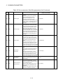
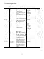
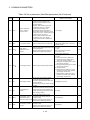
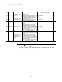
3.3 Servo Parameters .................................................................................................................................... 3-19
3.3.1 Servo parameters of servo amplifier................................................................................................. 3-19
3.3.2 Regenerative brake option................................................................................................................ 3-31
3.3.3 Absolute position detection system .................................................................................................. 3-31
3.3.4 Function selection A-1....................................................................................................................... 3-31
3.3.5 Auto tuning mode .............................................................................................................................. 3-31
3.3.6 Auto tuning response ........................................................................................................................ 3-32
3.3.7 In-position range................................................................................................................................ 3-32
3.3.8 Rotation direction selection............................................................................................................... 3-33
3.3.9 Encoder output pulse ........................................................................................................................ 3-33
3.3.10 Adaptive tuning mode ..................................................................................................................... 3-34
3.3.11 Vibration suppression control tuning mode .................................................................................... 3-34
3.3.12 Feed forward gain ........................................................................................................................... 3-34
3.3.13 Notch shape selection 1.................................................................................................................. 3-34
3.3.14 Notch shape selection 2.................................................................................................................. 3-35
3.3.15 Low pass filter selection.................................................................................................................. 3-35
3.3.16 Slight vibration suppression control selection ................................................................................ 3-35
3.3.17 Gain changing selection.................................................................................................................. 3-36
3.3.18 Encoder output pulse selection ...................................................................................................... 3-36
3.3.19 Function selection C-1 .................................................................................................................... 3-36
3.3.20 Function selection C-2 .................................................................................................................... 3-37
3.3.21 Analog monitor 1 output.................................................................................................................. 3-37
3.3.22 Analog monitor 2 output.................................................................................................................. 3-38
3.3.23 Function Selection C-4.................................................................................................................... 3-38
3.3.24 Alarm history clear........................................................................................................................... 3-38
3.3.25 Output signal device selection 1..................................................................................................... 3-39
3.3.26 Output signal device selection 2..................................................................................................... 3-39
3.3.27 Output signal device selection 3..................................................................................................... 3-39
3.3.28 Function selection D-3 .................................................................................................................... 3-40
4. AUXILIARY AND APPLIED FUNCTIONS
4- 1 to 4-47
4.1 Limit Switch Output Function ................................................................................................................... 4- 1
4.1.1 Operations ......................................................................................................................................... 4- 1
4.1.2 Limit output setting data .................................................................................................................... 4- 4
4.2 Absolute Position System ........................................................................................................................ 4- 8
4.2.1 Current value control......................................................................................................................... 4-10
4.3 High-Speed Reading of Specified Data .................................................................................................. 4-11
4.4 ROM Operation Function......................................................................................................................... 4-12
4.4.1 About the ROM operation function ................................................................................................... 4-12
4.4.2 Specifications of LED • switch .......................................................................................................... 4-15
4.4.3 ROM operation function details ........................................................................................................ 4-17
4.4.4 Operating procedure of "ROM writing" ............................................................................................. 4-23
A - 13
4.5 Security Function ..................................................................................................................................... 4-25
4.5.1 Password registration/change .......................................................................................................... 4-25
4.5.2 Password clearance.......................................................................................................................... 4-27
4.5.3 Password check ................................................................................................................................ 4-28
4.5.4 Password save .................................................................................................................................. 4-29
4.6 Clear All .................................................................................................................................................... 4-30
4.7 Communication via Network.................................................................................................................... 4-31
4.7.1 Specifications of the communications via network........................................................................... 4-32
4.7.2 Access range of the communications via network ........................................................................... 4-33
4.8 Monitor Function of the Main Cycle......................................................................................................... 4-39
4.9 Servo Parameter Reading Function ........................................................................................................ 4-40
4.10 Optional Data Monitor Function............................................................................................................. 4-41
4.11 Connect/Disconnect Function................................................................................................................ 4-42
A - 14
About Manuals
The following manuals are related to this product.
Referring to this list, please request the necessary manuals.
Related Manuals
(1) Motion controller
Manual Number
(Model Code)
Manual Name
Q173HCPU/Q172HCPU Motion controller User's Manual
This manual explains specifications of the Motion CPU modules, Q172LX Servo external signal interface
module, Q172EX Serial absolute synchronous encoder interface module, Q173PX Manual pulse
generator interface module, Teaching units, Power supply modules, Servo amplifiers, SSCNET
cables,
IB-0300110
(1XB910)
synchronous encoder cables and others.
(Optional)
Q173HCPU/Q172HCPU Motion controller (SV13/SV22) Programming Manual (Motion SFC)
This manual explains the functions, programming, debugging, error codes and others of the Motion SFC.
IB-0300112
(1XB912)
(Optional)
Q173HCPU/Q172HCPU Motion controller (SV13/SV22) Programming Manual (REAL MODE)
This manual explains the servo parameters, positioning instructions, device list, error list and others.
IB-0300113
(1XB913)
(Optional)
Q173HCPU/Q172HCPU Motion controller (SV22) Programming Manual (VIRTUAL MODE)
This manual describes the dedicated instructions use to the synchronous control by virtual main shaft,
mechanical system program create mechanical module.
IB-0300114
(1XB914)
This manual explains the servo parameters, positioning instructions, device list, error list and others.
(Optional)
Q173HCPU/Q172HCPU Motion controller (SV43) Programming Manual
This manual describes the dedicated instructions to execute the positioning control by Motion program of
EIA language (G-code).
This manual explains the servo parameters, positioning instructions, device list, error list and others.
(Optional)
A - 15
IB-0300115
(1XB915)
(2) PLC
Manual Number
(Model Code)
Manual Name
QCPU User's Manual (Hardware Design, Maintenance and Inspection)
This manual explains the specifications of the QCPU modules, power supply modules, base modules,
extension cables, memory card battery and others.
SH-080483ENG
(13JR73)
(Optional)
QCPU User's Manual (Function Explanation, Program Fundamentals)
This manual explains the functions, programming methods and devices and others to create programs
with the QCPU.
SH-080484ENG
(13JR74)
(Optional)
QCPU User's Manual (Multiple CPU System)
This manual explains the functions, programming methods and cautions and others to construct the
Multiple CPU system with the QCPU.
SH-080485ENG
(13JR75)
(Optional)
QCPU (Q Mode)/QnACPU Programming Manual (Common Instructions)
This manual explains how to use the sequence instructions, basic instructions, application instructions and
micro computer program.
SH-080039
(13JF58)
(Optional)
QCPU (Q Mode)/QnACPU Programming Manual (PID Control Instructions)
SH-080040
(13JF59)
This manual explains the dedicated instructions used to exercise PID control.
(Optional)
QCPU (Q Mode)/QnACPU Programming Manual (SFC)
This manual explains the system configuration, performance specifications, functions, programming,
debugging, error codes and others of MELSAP3.
SH-080041
(13JF60)
(Optional)
I/O Module Type Building Block User's Manual
SH-080042
(13JL99)
This manual explains the specifications of the I/O modules, connector, connector/terminal block
conversion modules and others.
(Optional)
(3) Servo amplifier
Manual Number
(Model Code)
Manual Name
MR-J3- B Servo amplifier Instruction Manual
This manual explains the I/O signals, parts names, parameters, start-up procedure and others for
MR-J3- B Servo amplifier.
SH-030051
(1CW202)
(Optional)
Fully Closed Loop Control MR-J3- B-RJ006 Servo amplifier Instruction Manual
This manual explains the I/O signals, parts names, parameters, start-up procedure and others for Fully
Closed Loop Control MR-J3- B-RJ006 Servo amplifier.
(Optional)
A - 16
SH-030056
(1CW304)
1 OVERVIEW
1. OVERVIEW
1
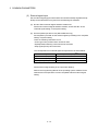
1.1 Overview
This programming manual describes the common items of each operating system
software, such as the Multiple CPU system of the operating system software packages
"SW5RN-SV Q ", "SW6RN-SV Q " for Motion CPU module
(Q173HCPU/Q172HCPU).
In this manual, the following abbreviations are used.
Generic term/Abbreviation
Q173HCPU/Q172HCPU or
Motion CPU (module)
Q172LX/Q172EX/Q173PX or
Motion module
Description
Q173HCPU/Q172HCPU/Q173HCPU-T/Q172HCPU-T Motion CPU module
Q172LX Servo external signals interface module/
(Note-1)
Q172EX-S2/-S3 Serial absolute synchronous encoder interface module
/
Q173PX(-S1) Manual pulse generator interface module
MR-J3- B
Servo amplifier model MR-J3- B
AMP or Servo amplifier
General name for "Servo amplifier model MR-J3- B"
QCPU, PLC CPU or PLC CPU module Qn(H)CPU
Multiple CPU system or Motion system Abbreviation for "Multiple PLC system of the Q series"
Abbreviation for "CPU No.n (n= 1 to 4) of the CPU module for the Multiple CPU
CPUn
system"
Programming software package
General name for "MT Developer" and "GX Developer"
Operating system software
General name for "SW RN-SV Q "
Operating system software for conveyor assembly use (Motion SFC) :
SV13
SW6RN-SV13Q
Operating system software for automatic machinery use (Motion SFC) :
SV22
SW6RN-SV22Q
SV43
Operating system software for machine tool peripheral use: SW5RN-SV43Q
MT Developer
GX Developer
Abbreviation for Integrated start-up support software package
"MT Developer (Version
(Note-2)
or later)"
Abbreviation for MELSEC PLC programming software package
"GX Developer (Version 6 or later)"
Manual pulse generator or MR-HDP01 Abbreviation for "Manual pulse generator (MR-HDP01)"
Serial absolute synchronous encoder
or Q170ENC
SSCNET
(Note-3)
(Note-3)
SSCNET
Absolute position system
Abbreviation for "Serial absolute synchronous encoder (Q170ENC)"
High speed synchronous network between Motion controller and servo
amplifier
High speed serial communication between Motion controller and servo
amplifier
General name for "System using the servomotor and servo amplifier for
absolute position"
Battery holder unit
Battery holder unit (Q170HBATC)
External battery
General name for "Q170HBATC" and "Q6BAT"
A 0BD-PCF
A10BD-PCF/A30BD-PCF SSC I/F board
1-1
1 OVERVIEW
Generic term/Abbreviation
SSC I/F communication cable
Teaching unit
Description
Abbreviation for "Cable for SSC I/F board/card"
A31TU-D3 /A31TU-DN
or A31TU-D3 /A31TU-DN
(Note-4)
Teaching unit
Abbreviation for "MELSECNET/H module/Ethernet module/CC-Link module/
Intelligent function module
Serial communication module"
(Note-1) : Q172EX can be used in SV22.
(Note-2) : Refer to Section "1.3.4 Software packages" for the correspondence version.
(Note-3) : SSCNET: Servo System Controller NETwork
(Note-4) : Teaching unit can be used in SV13.
REMARK
For information about the each module, design method for program and parameter,
refer to the following manuals relevant to each module.
Item
Reference Manual
Motion CPU module/Motion unit
Q173HCPU/Q172HCPU User’s Manual
PLC CPU, peripheral devices for PLC program design, I/O
modules and intelligent function module
Operation method for MT Developer
Help of each software
• Design method for Motion SFC program
• Design method for Motion SFC parameter
• Motion dedicated PLC instruction
SV13/SV22
Manual relevant to each module
Q173HCPU/Q172HCPU Motion controller (SV13/SV22)
Programming Manual (Motion SFC)
• Design method for positioning control
program in the real mode
Q173HCPU/Q172HCPU Motion controller (SV13/SV22)
• Design method for positioning control
Programming Manual (REAL MODE)
parameter
SV22
(Virtual mode)
• Design method for mechanical system
program
Q173HCPU/Q172HCPU Motion controller (SV22)
Programming Manual (VIRTUAL MODE)
• Design method for Motion program
SV43
• Motion dedicated PLC instruction
Q173HCPU/Q172HCPU Motion controller (SV43)
• Design method for positioning control
Programming Manual
parameter
1-2
1 OVERVIEW
1.2 Features
The Motion CPU and Multiple CPU system have the following features.
1.2.1 Features of Motion CPU
(1) Q series PLC Multiple CPU system
(a) The load of control processing for each CPU can be distributed by
controlling the complicated servo control with the Motion CPU, and the
machine control or information control with the PLC CPU, and flexible
system configuration can be realized.
(b) The Motion CPU and PLC CPU are selected flexibly, and the Multiple CPU
system up to 4 CPU modules can be realized.
The Motion CPU module for the number of axis to be used can be selected.
Q173HCPU
: Up to 32 axes
Q172HCPU
: Up to 8 axes
(Note): Combination with Q173CPU(N)/Q172CPU(N) is also possible.
The PLC CPU module for the program capacity to be used can be selected.
(One or more PLC CPU is necessary with the Multiple CPU system.)
Q00CPU
: 8k steps
Q01CPU
: 14k steps
Q02CPU, Q02HCPU
: 28k steps
Q06HCPU
: 60k steps
Q12HCPU
: 124k steps
Q25HCPU
: 252k steps
(c) The device data access of the Motion CPU and the Motion SFC program
(SV13/SV22)/Motion program (SV43) start can be executed from PLC CPU
by the Motion dedicated PLC instruction.
(2) High speed operation processing
(a) The minimum operation cycle of the Motion CPU is made 0.44[ms] (so far,
the ratio of 2 times), and it correspond with high frequency operation.
(Note): The minimum operation cycle of Q173CPU(N)/Q172CPU(N) is 0.88[ms].
(b) High speed PLC control is possible by the Q series PLC CPU.
(For LD instruction)
Q02HCPU, Q06HCPU, Q12HCPU, Q25HCPU : 0.034[µs]
: 0.079[µs]
Q02CPU
: 0.16[µs]
Q00CPU
: 0.10[µs]
Q01CPU
1-3
1 OVERVIEW
(3) Connection between the Motion controller and servo amplifier with
high speed synchronous network by SSCNET
(a) High speed synchronous network by SSCNET connect between the
Motion controller and servo amplifier, and batch control the charge of servo
parameter, servo monitor and test operation, etc.
It is also realised reduce the number of wires.
(b) The maximum distance between the Motion CPU and servo amplifier, servo
amplifier and servo amplifier of the SSCNET cable on the same bus was
set to 50(164.04)[m(ft.)], and the flexibility improved at the Motion system
design.
(4) The operating system software package for your application needs
By installing the operating system software for applications in the internal flash
memory of the Motion CPU, the Motion controller suitable for the machine can be
realized.
And, it also can correspond with the function improvement of the software
package.
(a) Conveyor assembly use (SV13)
Offer liner interpolation, circular interpolation, helical interpolation, constantspeed control, speed control, fixed-pitch feed and etc. by the dedicated
servo instruction. Ideal for use in conveyors and assembly machines.
(b) Automatic machinery use (SV22)
Provides synchronous control and offers electronic cam control by
mechanical support language. Ideal for use in automatic machinery.
(c) Machine tool peripheral use (SV43)
Offer liner interpolation, circular interpolation, helical interpolation, constantspeed positioning and etc. by the EIA language (G-code). Ideal for use in
machine tool peripheral.
1-4
1 OVERVIEW
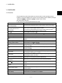
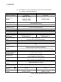
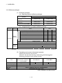
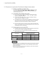
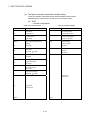
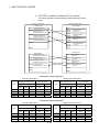
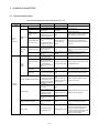
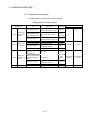
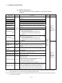
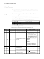
1.2.2 Basic specifications of Q173HCPU/Q172HCPU
(1) Module specifications
Item
Q173HCPU
Q173HCPU-T
Q172HCPU
Q172HCPU-T
Teaching unit
——
Usable
——
Usable
Internal current consumption
(5VDC) [A]
1.25
1.56 (Note)
1.14
1.45 (Note)
Mass [kg]
0.23
0.24
0.22
0.23
Exterior dimensions [mm(inch)]
104.6 (4.11)(H)
27.4 (1.08)(W)
114.3 (4.50)(D)
(Note) : Current consumption 0.26[A] of the teaching unit is included.
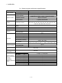
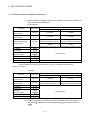
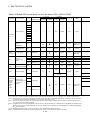
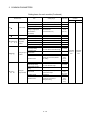
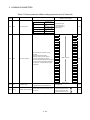
(2) SV13/SV22 Motion control specifications/performance
specifications
(a) Motion control specifications
Item
Q173HCPU
Number of control axes
Q173HCPU-T
Q172HCPU
Up to 32 axes
Q172HCPU-T
Up to 8 axes
0.44ms/ 1 to 3 axes
SV13
0.88ms/ 4 to 10 axes
0.44ms/ 1 to 3 axes
1.77ms/11 to 20 axes
0.88ms/ 4 to 8 axes
3.55ms/21 to 32 axes
Operation cycle
(default)
0.88ms/ 1 to 5 axes
SV22
1.77ms/ 6 to 14 axes
3.55ms/15 to 28 axes
0.88ms/ 1 to 4 axes
——
——
1.77ms/ 5 to 8 axes
7.11ms/29 to 32 axes
Linear interpolation (Up to 4 axes), Circular interpolation (2 axes),
Interpolation functions
Helical interpolation (3 axes)
PTP(Point to Point) control, Speed control, Speed-position control, Fixed-pitch feed,
Control modes
Constant speed control, Position follow-up control, Speed control with fixed position stop,
Speed switching control, High-speed oscillation control, Synchronous control (SV22)
Acceleration/
Automatic trapezoidal acceleration/deceleration,
deceleration control
Compensation
S-curve acceleration/deceleration
Backlash compensation, Electronic gear, Phase compensation (SV22)
Programming language
Motion SFC, Dedicated instruction, Mechanical support language (SV22)
Servo program capacity
14k steps
Number of positioning
3200 points
points
(Positioning data can be designated indirectly)
Programming tool
IBM PC/AT
Peripheral I/F
Teaching operation
function
Home position return
function
USB/SSCNET
None
Provided (SV13 use)
None
Provided (SV13 use)
Proximity dog type (2 types), Count type (3 types), Data set type (2 types), Dog cradle type,
Stopper type (2 types), Limit switch combined type
(Home position return re-try function provided, home position shift function provided)
JOG operation function
Provided
1-5
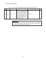
1 OVERVIEW
Motion control specifications (continued)
Item
Q173HCPU
Q173HCPU-T
Manual pulse generator
operation function
Possible to connect 12 modules
M-code completion wait function provided
Limit switch output
Number of output points 32 points
function
Watch data: Motion control data/Word device
Absolute position system
Number of SSCNET
(Note-1)
Motion related interface
module
Possible to connect 8 modules
M-code output function provided
M-code function
systems
Q172HCPU-T
Possible to connect 3 modules
operation function
Synchronous encoder
Q172HCPU
Made compatible by setting battery to servo amplifier.
(Possible to select the absolute data method or incremental method for each axis)
2 systems
1 system
Q172LX : 4 modules usable
Q172LX : 1 module usable
Q172EX : 6 modules usable
Q173PX : 4 modules usable
Q172EX : 4 modules usable
(Note-2)
Q173PX : 3 modules usable
(Note-2)
(Note-1) : The servo amplifiers for SSCNET cannot be used.
(Note-2) : When using the incremental synchronous encoder (SV22 use), you can use above number of modules.
When connecting the manual pulse generator, you can use only 1 module.
1-6
1 OVERVIEW
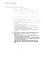
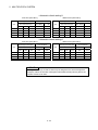
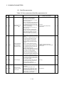
(b) Motion SFC Performance Specifications
Item
Q173HCPU/Q172HCPU
Code total
(Motion SFC chart+ Operation control+
Motion SFC program capacity Transition)
543k bytes
Text total
(Operation control+ Transition)
484k bytes
Number of Motion SFC programs
256 (No.0 to 255)
Motion SFC chart size/program
Motion SFC program
Up to 64k bytes (Included Motion SFC chart comments)
Number of Motion SFC steps/program
Up to 4094 steps
Number of selective branches/branch
255
Number of parallel branches/branch
255
Parallel branch nesting
Up to 4 levels
Number of operation control programs
4096 with F(Once execution type) and FS(Scan execution type)
combined. (F/FS0 to F/FS4095)
Number of transition programs
Operation control program
(F/FS)
/
Transition program
(G)
4096(G0 to G4095)
Code size/program
Up to approx. 64k bytes (32766 steps)
Number of blocks(line)/program
Up to 8192 blocks (in the case of 4 steps(min)/blocks)
Number of characters/block(line)
Up to 128 (comment included)
Number of operand/block
Up to 64 (operand: constants, word device, bit devices)
( ) nesting/block
Up to 32 levels
Operation control program
Descriptive
expression Transition program
Calculation expression/bit conditional expression
Calculation expression/bit conditional expression/
comparison conditional expression
Number of multi execute programs
Up to 256
Number of multi active steps
Up to 256 steps/all programs
Normal task
Execute specification
Execute in motion main cycle
Event task Fixed cycle
(Execution
Executed
External
can be
task
interrupt
masked.)
PLC interrupt
Execute in fixed cycle
(0.88ms, 1.77ms, 3.55ms, 7.11ms, 14.2ms)
Execute when input ON is set among interrupt module QI60
(16 points).
Execute with interrupt instruction (S(P).GINT) from PLC CPU.
Execute when input ON is set among interrupt module QI60
(16 points).
NMI task
Number of I/O points (X/Y)
8192 points
Number of real I/O points
(PX/PY)
256 points
Number of devices
(Device In the Motion CPU
only)
(Included the positioning
dedicated device)
Internal relays
(M)
Latch relays
(L)
Link relays
(B)
8192 points
Annunciators
(F)
2048 points
Special relays
(M)
256 points
Data registers
(D)
8192 points
Link registers
(W)
8192 points
Special registers
(D)
256 points
Motion registers
(#)
Coasting timers
(FT)
8192 points
1 point (888µs)
Total (M + L) : 8192 points
1-7
1 OVERVIEW
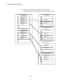
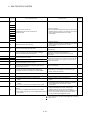
(3) SV43 Motion control specifications/performance specifications
(a) Motion control specifications
Item
Number of control axes
Q173HCPU
Q172HCPU
Up to 32 axes
Up to 8 axes
0.88ms/ 1 to 5 axes
Operation cycle
1.77ms/ 6 to 14 axes
0.88ms/ 1 to 5 axes
(default)
3.55ms/15 to 28 axes
1.77ms/ 6 to 8 axes
7.11ms/29 to 32 axes
Interpolation functions
Control modes
Acceleration/
Linear interpolation (Up to 4 axes), Circular interpolation (2 axes),
Helical interpolation (3 axes)
PTP (Point to Point) control, Constant speed positioning, High-speed oscillation control
Automatic trapezoidal acceleration/deceleration,
deceleration control
Compensation
S-curve acceleration/deceleration
Backlash compensation, Electronic gear
Programming language
Dedicated instruction (EIA language)
Motion program capacity
248k bytes
Number of programs
Number of simultaneous
start programs
1024
Axis designation program : 32
Axis designation program : 8
Control program : 16
Control program : 16
Number of positioning
points
Approx. 10600 points
(Positioning data can be designated indirectly)
Programming tool
IBM PC/AT
Peripheral I/F
USB/SSCNET
Teaching operation
None
function
Home position return
function
Proximity dog type (2 types), Count type (3 types), Data set type (2 types), Dog cradle type,
Stopper type (2 types), Limit switch combined type
(Home position return re-try function provided, home position shift function provided)
JOG operation function
Provided
Manual pulse generator
Possible to connect 3 modules
operation function
M-code function
M-code output function provided
M-code completion wait function provided
Limit switch output
function
Number of output points 32 points
Watch data: Motion control data/Word device
Skip function
Provided
Override ratio setting
Override ratio setting : 0 to 100[%]
function
Absolute position system
Number of SSCNET
Made compatible by setting battery to servo amplifier.
(Possible to select the absolute data method or incremental method for each axis)
2 systems
1 system
Number of Motion related
Q172LX : 4 modules
Q172LX : 1 module
modules
Q173PX : 1 module
Q173PX : 1 module
systems
(Note-1)
(Note-1) : The servo amplifiers for SSCNET cannot be used.
1-8
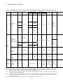
1 OVERVIEW
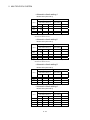
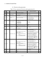
(b) Motion program performance specifications
Item
Program capacity
Q173HCPU/Q172HCPU
Total of program files
Number of programs
Arithmetic operation
Operation controls
Comparison operation
M-codes
Special M-codes
Variable
Functions
Positioning command
Numerical function
Speed/torque setting
Motion control
Jump/repetition processing
Data operation
Number of controls
G00, G01, G02, G03, G04, G09, G12, G13, G23, G24, G25, G26,
G28, G30, G32, G43, G44, G49, G53, G54, G55, G56, G61, G64,
G90, G91, G92, G98, G99, G100, G101
Output command to data
register
Program control command
Device variable
Trigonometric function
Start/end
Home position return
Instructions
Equal to, Not equal to
Logical shift operation, Logical negation, Logical AND,
Logical OR, Exclusive OR
Logical operation
G-codes
248k bytes
Up to 1024 (No. 1 to 1024)
Unary operation, Addition and subtraction operation,
Multiplication and division operation, Remainder operation
M****
M00, M01, M02, M30, M98, M99, M100
X, Y, B, F, D, W, #
SIN, COS, TAN, ASIN, ACOS, ATAN
ABS, SQR, BIN, LN, EXP, BCD, RND, FIX, FUP, INT, FLT, DFLT,
SFLT
CALL, CLEAR
CHGA
TL, CHGV, CHGT
WAITON, WAITOFF, EXEON, EXEOFF
CALL, GOSUB/GOSUBE, IF…GOTO, IF…THEN…ELSE…END,
WHILE…DO…END
BMOV, BDMOV, FMOV, BSET, BRST, SET, RST, MULTW,
MULTR, TO, FROM, ON, OFF, IF…THEN…SET/RST/OUT, PB
Number of program calls
(GOSUB/GOSUBE)
Number of program calls (M98)
Up to 8
Up to 8
Number of I/O points
(X/Y)
8192 points
Number of real I/O
points (PX/PY)
256 points
Internal relays
Latch relays
Link relays
Number of devices
(Device In the Motion Annunciators
Special relays
CPU only)
(Included the
Data registers
positioning dedicated Link registers
device)
Special registers
Motion registers
Coasting timers
(M)
(L)
(B)
(F)
(M)
(D)
(W)
(D)
(#)
(FT)
Total (M + L) : 8192 points
8192 points
2048 points
256 points
8192 points
8192 points
256 points
8192 points
1 point (888µs)
1-9
1 OVERVIEW
1.3 Hardware Configuration
This section describes the Q173HCPU/Q172HCPU system configuration, precautions
on use of system, and configured equipments.
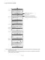
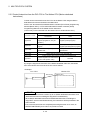
1.3.1 Motion system configuration
This section describes the equipment configuration, configuration with peripheral
devices and system configuration in the Q173HCPU/Q172HCPU system.
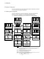
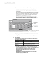
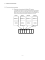
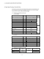
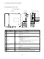
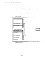
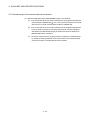
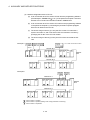
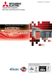
(1) Equipment configuration in Q173HCPU/Q172HCPU system
Extension of the Q series module
Power supply module/
QCPU/ I/O module/ Intelligent
function module of the Q series
Motion module
(Q172LX, Q172EX, Q173PX)
Motion module
(Q172LX, Q172EX, Q173PX)
Extension cable
(QC B)
CPU base unit
(Q33B, Q35B, Q38B, Q312B)
(Note-5)
(Note-1)
Q6 B extension base unit
(Q63B, Q65B, Q68B, Q612B)
(Note-2)
BAT
CPU
PASSED
Q170HBAT
DATE
Battery holder unit
(Q170HBATC)
Short-circuit connector for
the teaching unit
(Q170TUTM)
Motion CPU module
(Q173HCPU/Q172HCPU)
(Note-3)
Power supply module/
I/O module/Intelligent function
module of the Q series
(Note-5) (Note-6)
SVO ON
MITSUBISHI
LITHIUM BATTERY
Battery
(Q6BAT)
SSCNET cable
(MR-J3BUS M(-A/-B))
Cable for the teaching unit
(Q170TUD CBL M(-A))
Teaching unit
(A31TU-D3 , A31TU-DN )
(Note-4)
Short-circuit connector for
the teaching unit
(A31TUD3TM)
Servo amplifier
(MR-J3- B)
It is possible to select the best according to the system.
(Note-1) : When using the external battery, be sure to connect the Battery holder unit (Q170HBATC).
And be sure to set the Battery(Q6BAT) to the Battery holder unit (Q170HBATC).
Battery(Q6BAT) is optional.
(Note-2) : It is possible to use only Q173HCPU-T/Q172HCPU-T.
It is packed together with Q173HCPU-T/Q172HCPU-T.
(Note-3) : It varies by the connecting teaching unit.
(Note-4) : It is packed together with Q170TUD CBL M.
(Note-5) : When using the A31TU-D3 /A31TU-DN , be sure to use the Q173HCPU-T/Q172HCPU-T.
(Note-6) : A31TU-D3 /A31TU-DN corresponds to only Japanese.
It does not correspond to display for English.
1 - 10
1 OVERVIEW
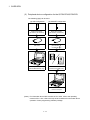
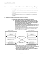
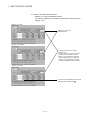
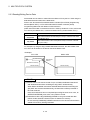
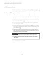
(2) Peripheral device configuration for the Q173HCPU/Q172HCPU
The following (a)(b) can be used.
(a) USB configuration
(b) SSCNET configuration
Motion CPU module
(Q173HCPU, Q172HCPU)
Motion CPU module
(Q173HCPU, Q172HCPU)
USB cable
SSC I/F communication cable
(Q170CDCBL M,
Q170BDCBL M)
MITSUBISHI
SSCNET
CARD
A30CD-PCF
Personal computer
(Windows 98/2000/XP only)
R
SSC I/F Card/Board
(A30CD-PCF/A 0BD-PCF)
Personal computer
(Note) : For information about GPP functions of PLC CPU, refer to the operating
manual of PLC. Also, refer to the help of each software for information about
operation of each programming software package.
1 - 11
1 OVERVIEW
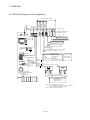
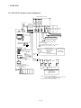
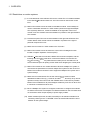
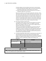
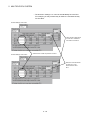
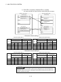
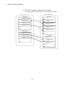
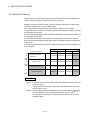
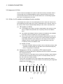
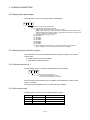
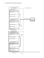
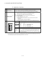
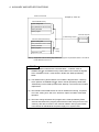
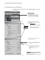
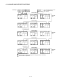
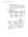
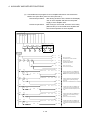
1.3.2 Q173HCPU System overall configuration
Q61P-A
Qn(H)
CPU
Manual pulse
generator
interface module
PLC CPU/
Motion CPU
Synchronous
encoder
interface module
CPU base
unit
(Q3 B)
Servo external
signals
interface module
Motion CPU control module
Q173H Q172LX Q172EX Q172PX QI60
CPU
-S2/-S3 (-S1)
QX
Q6 AD
QY
Q6 DA I/O module of the Q Series or
Special function module
100/200VAC
(Note-2)
Analogue input/output
USB
Input/output (Up to 256 points)
Interrupt signals (16 points)
Personal Computer
IBM PC/AT
P
Manual pulse generator 3/module
(MR-HDP01) (Up to 1 module)
Serial absolute synchronous encoder cable
(Q170ENCCBL M)
Battery holder
unit
Q170HBATC
E
Serial absolute synchronous encoder
(Q170ENC)(Up to 6 modules)
Teaching
A31TU-D3 /A31TU-DN
2/module
unit (Note-1)
External input signals
Cable for the teaching
unit
(Q170TUD CBL M(-A))
SSC I/F
Communication
cable
(Q170CDCBL M/
Q170BDCBL M)
SSC I/F Card/Board
(A30CD-PCF/A 0BD-PCF)
Panel Personal Computer
(WinNT/Win98/Win2000/WinXP)
Computer link SSC
SSCNET
cable
SSCNET
SSCNET
8 axes/module
(Up to 4 modules)
(CN1)
(CN2)
M
E
d1
d16
d1
Extension base unit
(Q6 B)
M
E
M
E
d16
M
E
MR-J3- B model Servo amplifier,
Up to 32 axes (Up to 16 axes/system)
Power supply
module
Extension
cable
Number of Inputs
FLS
: Upper stroke limit
RLS
: Lower stroke limit
STOP
: Stop signal
DOG/CHANGE : Proximity dog/
Speed-position switching
External input signals of servo amplifier
Proximity dog
Upper stroke limit
Lower stroke limit
UP to 7 extensions
(Note-1) : Be sure to use the Q173HCPU-T.
A31TU-D3 /A31TU-DN corresponds to only Japanese.
It does not correspond to display for English.
(Note-2) : QI60 can be used in SV13/SV22.
1 - 12
1 OVERVIEW
CAUTION
Construct a safety circuit externally of the Motion controller or servo amplifier if the abnormal
operation of the Motion controller or servo amplifier differ from the safety directive operation in
the system.
The ratings and characteristics of the parts (other than Motion controller, servo amplifier and
servomotor) used in a system must be compatible with the Motion controller, servo amplifier and
servomotor.
Set the parameter values to those that are compatible with the Motion controller, servo amplifier,
servomotor and regenerative resistor model and the system application. The protective functions
may not function if the settings are incorrect.
When a teaching unit is used, the cable for the teaching unit is necessary between the Motion
CPU (Q173HCPU-T/Q172HCPU-T) and teaching unit. And, connect the short-circuit connector
for teaching unit, after removing the teaching unit or when not using it.
1 - 13
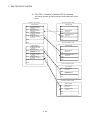
1 OVERVIEW
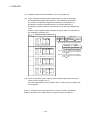
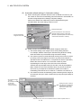
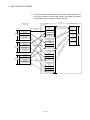
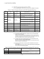
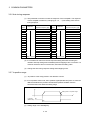
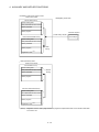
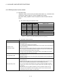
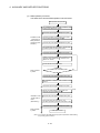
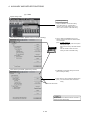
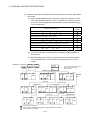
1.3.3 Q172HCPU System overall configuration
Q61P-A
Qn(H)
CPU
Manual pulse
generator
interface module
PLC CPU/
Motion CPU
Synchronous
encoder
interface module
CPU base
unit
(Q3 B)
Servo external
signals
interface module
Motion CPU control module
Q172H Q172LX Q172EX Q172PX QI60
CPU
-S2/-S3 (-S1)
QX
Q6 AD
QY
Q6 DA I/O module of the Q Series or
Special function module
100/200VAC
(Note-2)
Analogue input/output
USB
Input/output (Up to 256 points)
Interrupt signals (16 points)
Personal Computer
IBM PC/AT
P
Manual pulse generator 3/module
(MR-HDP01) (Up to 1 module)
Serial absolute synchronous encoder cable
(Q170ENCCBL M)
Battery holder
unit
Q170HBATC
E
Serial absolute synchronous encoder
(Q170ENC) (Up to 4 modules)
2/module
unit (Note-1)
Teaching
A31TU-D3 /A31TU-DN
External input signals
Cable for the teaching
unit
(Q170TUD CBL M(-A))
SSC I/F
Communication
cable
(Q170CDCBL M/
Q170BDCBL M)
SSC I/F Card/Board
(A30CD-PCF/A 0BD-PCF)
Panel Personal Computer
(WinNT/Win98/Win2000/WinXP)
Computer link SSC
SSCNET
cable
SSCNET
(CN1)
d2
d1
M
E
Extension base unit
(Q6 B)
M
E
8 axes/module
(Up to 1 module)
d3
M
E
d8
M
E
MR-J3- B model Servo amplifier,
Up to 8 axes
Power supply
module
Extension
cable
Number of Inputs
FLS
: Upper stroke limit
RLS
: Lower stroke limit
STOP
: Stop signal
DOG/CHANGE : Proximity dog/
Speed-position switching
External input signals of servo amplifier
Proximity dog
Upper stroke limit
Lower stroke limit
UP to 7 extensions
(Note-1) : Be sure to use the Q173HCPU-T.
A31TU-D3 /A31TU-DN corresponds to only Japanese.
It does not correspond to display for English.
(Note-2) : QI60 can be used in SV13/SV22.
1 - 14
1 OVERVIEW
CAUTION
Construct a safety circuit externally of the Motion controller or servo amplifier if the abnormal
operation of the Motion controller or servo amplifier differ from the safety directive operation in
the system.
The ratings and characteristics of the parts (other than Motion controller, servo amplifier and
servomotor) used in a system must be compatible with the Motion controller, servo amplifier and
servomotor.
Set the parameter values to those that are compatible with the Motion controller, servo amplifier,
servomotor and regenerative resistor model and the system application. The protective functions
may not function if the settings are incorrect.
When a teaching unit is used, the cable for the teaching unit is necessary between the Motion
CPU (Q173HCPU-T/Q172HCPU-T) and teaching unit. And, connect the short-circuit connector
for teaching unit, after removing the teaching unit or when not using it.
1 - 15
1 OVERVIEW
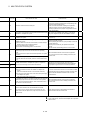
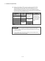
1.3.4 Software packages
(1) Software packages
(a) Operating system software packages
Software package
Application
For conveyor assembly SV13
(Motion SFC)
For automatic machinery SV22
(Motion SFC)
For machine tool peripheral SV43
Q173HCPU
Q172HCPU
SW6RN-SV13QK
SW6RN-SV13QM
SW6RN-SV22QJ
SW6RN-SV22QL
SW5RN-SV43QJ
SW5RN-SV43QL
(b) Integrated start-up support software package
Part name
Model name
Details
Version
00K
SW6RNC-GSVE (Integrated start-up support software (1 CD-ROM) )
SW6RNCGSVPROE
MT Developer
00M
00N
Conveyor assembly software
: SW6RN-GSV13P
00J
00K
00L
Automatic machinery software
: SW6RN-GSV22P
00J
00K
00L
Machine tool peripheral software : SW6RN-GSV43P
——
00F
00G
Cam data creation software
: SW3RN-CAMP
00M
00M
00M
Digital oscilloscope software
: SW6RN-DOSCP
00G
00H
00H
Communication system software : SW6RN-SNETP
00J
00K
00L
Document print software
00R
00M
00T
00Q
00W
00T
R
XP English
: SW3RN-DOCPRNP,
SW20RN-DOCPRNP
SW6RNC-GSVHELPE (Operation manual (1 CD-ROM) )
Installation manual
SW6RNC-GSVPROE
SW6RNCGSVSETE
A30CD-PCF(SSC I/F card (PCMCIA TYPE
1CH/card) )
Q170CDCBL3M (A30CD-PCF cable 3m (9.84ft.) )
(Note) : Operating environment of the MT Developer is WindowsNT
version only.
R
4.0/Windows
R
98/Windows
R
2000/Windows
(2) Operating environment of personal computer
Operating environment is shown below.
IBM PC/AT with which WindowsNT 4.0/Windows 98/Windows 2000/
Windows XP English version operates normally.
R
R
R
R
R
WindowsNT 4.0
Item
(Service Pack 2 or later) (Note)
R
R
Windows 2000
Windows XP
R
or Windows 98
CPU
Memory capacity
Hard disk free space
Disk drive
Display
R
Pentium 133MHz or more
Pentium
R
233MHz or more
Pentium
R
450MHz or more
Recommended 32MB or more Recommended 64MB or more Recommended 192MB or more
Hard disk free space is as following list.
3.5inch (1.44MB) floppy disk drive, CD-ROM disk drive
800×600 pixels, 256 colors or more
(Note) : Impossible to use USB connection.
1 - 16
1 OVERVIEW
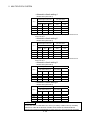
It is necessary the following capacity depending on the installed software.
Size
Model name
SW6RNC-GSVE
SW6RNC-GSVHELPE
SW6RN-GSV13P
65MB
40MB
SW6RN-GSV22P
66MB
45MB
SW6RN-GSV43P
55MB
32MB
SW3RN-CAMP
5MB
3MB
SW6RN-DOSCP
35MB
10MB
SW6RN-SNETP
Standard
60MB
Custom (When all selection)
60.5MB
3MB
SW3RN-DOCPRNP
45MB
5MB
SW20RN-DOCPRNP
45MB
5MB
R
R
(Note-1) : WindowsNT , Windows are either registered trademarks or trademarks of Microsoft Corporation
in the United States and/or other countries.
R
(Note-2) : Pentium are trademarks or registered trademarks of Intel Corporation or its subsidiaries in the
United States and other countries.
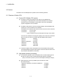
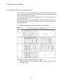
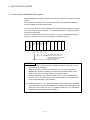
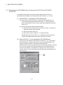
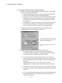
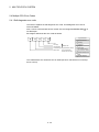
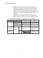
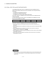
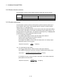
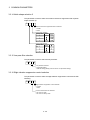
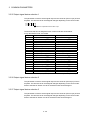
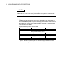
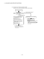
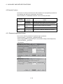
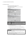
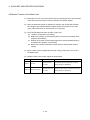
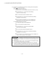
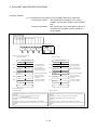
(3) Operating system(OS) type/version
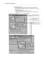
(a) Confirmation method in the operating system(OS)
SOFTWARE
PACKAGE
3.5inch
1)
T
2)
3)
4)
5)
1) OS software TYPE
2) Software version
3) OS software version
4) Serial number
5) Number of FD
MITSUBISHI ELECTRIC CORPORATION ALL
RIGHTS RESERVED
Example) When using the Q173HCPU, SV13 and version A.
1) SW6RN-SV13QK
2) BCD-B14W311
3) A
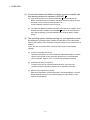
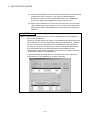
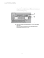
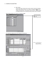
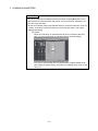
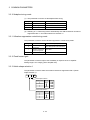
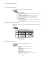
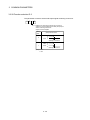
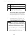
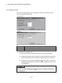
(b) Confirmation method in the SW6RN-GSV P
The operating system(OS) type/version of the connected CPU is displayed
on the installation screen of the SW6RN-GSV P.
(Motion SFC-compatible OS)
S
V
1
J or L : Q173HCPU
K or M: Q172HCPU
1 - 17
3
Q
K
V
E
R
3
0
0
A
U
OS version
Indicates Motion SFC compatibility.
Indicates teaching unit usable.
1 OVERVIEW
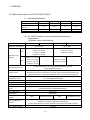
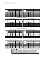
(4) Relevant software packages
(a) PLC software package
Model name
Software package
GX Developer
SW D5C-GPPW-E
(Note) :
=used "6" or later.
(b) Servo setup software package
Model name
Software package
MR Configurator
MRZJW3-SETUP221E
POINT
(1) When the operation of Windows is not unclear in the operation of this software,
refer to the manual of Windows or guide-book from the other supplier.
(2) The screen might not be correctly displayed depending on the system font size
of WindowsNT 4.0/Windows 98/Windows 2000/Windows XP.
Be sure to use the small size fonts.
R
R
1 - 18
R
R
1 OVERVIEW
1.3.5 Restrictions on motion systems
(1) It is not allowed to use the Motion CPU as the control CPU of a module installed
on the QA1S6 B extension base unit. PLC CPU must be used as the control
CPU.
(2) Motion CPU module cannot be used as standalone module. It must always be
used in combination with the PLC CPU module (version that supports Multiple
CPU systems). Moreover, it must be installed on the right side of PLC CPU
module. PLC CPU module cannot be installed in a position to the right of Motion
CPU module.
(3) Personal computer CPU unit must be installed on the right side of Motion CPU
module. Motion CPU module cannot be installed in a position to the right of
personal computer CPU unit.
(4) Make sure to use the PLC CPU module in the "Q mode."
(5) Motion CPU module cannot be set as the control CPU of intelligent function
module or Graphic Operation Terminal (GOT).
(6) SSCNET cable which connects the Motion CPU and servo amplifier, and the
teaching unit connecting cable which connects the Motion CPU and A31TU(Note-1)
D3 /A31TU-DN
are pulled from the bottom part of unit. Make sure to
secure sufficient space for pulling out the cable when designing the control panel.
(7) Motion CPU module is one module element of Q series multiple PLC system. It
must be set the parameters of Q series multiple PLC system for each PLC CPU.
Motion CPU module must also be set to support the Multiple CPU system in the
system settings.
(8) Make sure to use the Motion CPU as the control CPU of motion modules
(Note-2)
dedicated for Motion CPU (e.g., Q172LX, Q172EX
, Q173PX). They will not
operate correctly if PLC CPU is set and installed as the control CPU by mistake.
Motion CPU is treated as a 32-point intelligent module by PLC CPU of other CPU.
It cannot be accessed from other CPU.
(9) When a Multiple CPU system is configured, make sure to configure the modules
so that the total current consumption of individual modules on the CPU base does
not exceed the 5VDC output capacity of power supply module.
(10) Motion modules (Q172LX, Q172EX, Q173PX) is to do selection whether to be
necessary referring to the "3. DESIGN" of the "Q173HCPU/Q172HCPU User's
Manual" for the system design.
1 - 19
1 OVERVIEW
(Note-2)
(11) Installation position of the Q172EX
is only CPU base unit.
(12) When combining the Q173HCPU(-T)/Q172HCPU(-T) with Q173CPU(N)/
Q172CPU(N)/Q173CPUN-T/Q172CPUN-T, set as following combination.
If it is used in combination except for the following, the Q173HCPU(-T)/
Q172HCPU(-T) does not operate normally, such as Q173HCPU(-T)/
Q172HCPU(-T) does not start or communication error with servo amplifier will
occur.
However, all the operating system software are SV43, there is no restriction for
the combination of Motion CPU.
Installation example of Motion CPU
PLC CPU
2
Power supply
CPU
PLC CPU
3
Power supply
CPU
PLC CPU
4
Power supply
CPU
0
Abbreviation
Model name
Q17 HCPU Q17 HCPU(-T)
Q17 CPU Q17 CPU(N)/Q17 CPUN(-T)
1
Q17 Q17 H
CPU CPU
(Note-1) :Be sure to install the following operating
system software to the Q17 CPU.
(Note-1) (Note-2)
0
1
2
Q17 Q17 H Q17 H
CPU CPU CPU
(Note-1) (Note-2) (Note-2)
0
Q17
CPU
1
Q17
CPU
2
Application
SV13/SV22
Version
00R or later
(Note-2): There is no restriction for the operating
system software and version installed to
the Q17 HCPU.
(Note-3): There is no restriction for the operating
system software and version installed to
the Q17 CPU.
Q17 H
CPU
(Note-1) (Note-3) (Note-2)
0
PLC CPU
PLC CPU
1
Power supply
CPU
1
Q17
CPU
2
Q17 H
CPU
(Note-1) (Note-2)
(13) When the operation cycle is 0.4[ms], set the system setting as the axis select
switch of servo amplifier "0 to 7".
If the axis select switch of servo amplifier "8 to F" is set, the servo amplifiers are
not recognized.
(Note-1) : Teaching unit can be used in SV13. It cannot be used in SV22/SV43.
(Note-2) : Q172EX can be used in SV22. It cannot be used in SV13/SV43.
1 - 20
2 MULTIPLE CPU SYSTEM
2. MULTIPLE CPU SYSTEM
2.1 Multiple CPU System
2.1.1 Overview
(1) Multiple CPU System
Multiple (up to 4 modules) PLC CPUs and Motion CPUs are installed to the CPU
base unit, and each CPU controls the I/O modules and intelligent function
modules of the CPU base unit/extension base unit slot by slot in the Multiple
CPU system.
Each Motion CPU controls the servo amplifiers connected by SSCNET cable.
(2) Distributed system configuration
(a) By distributing such tasks as servo control, machine control and information
control among multiple processors, the flexible system configuration can be
realized.
(b) You can increase the number of control axes by using a multiple Motion
CPUs. It is possible to control up to 96 axes by using three Q173HCPUs.
(c) You can reduce the PLC scan time of the overall system by using a multiple
PLC CPUs and distributing the PLC control load among them.
(3) Communication among the CPUs in the Multiple CPU system
(a) Transmission of data among the CPUs in the Multiple CPU system is
performed automatically using the multiple CPU automatic refresh function.
This makes it possible to use the device data of the other CPUs as the
device data of the self CPU.
(b) You can access the device data and start the Motion SFC program
(SV13/SV22)/Motion program (SV43) from the PLC CPU to the Motion CPU
by Motion dedicated PLC instruction.
2-1
2
2 MULTIPLE CPU SYSTEM
2.1.2 Installation of PLC CPU and Motion CPU
Up to a total four PLC CPUs and Motion CPUs can be installed in the CPU base unit,
in the four slots starting from the CPU slot (the slot located to the immediate right of the
power supply module) to slot 2 in series.
There must be no non-installation slot left, between a PLC CPU and a Motion CPU, or
between Motion CPUs.
When two or more Motion CPUs are installed, they are installed together in the slots
provided to the right of one or more PLC CPUs. (PLC CPU cannot be installed to the
right of a Motion CPU.)
(1) When the high performance model PLC CPU is used.
Number of
CPUs
I/O, etc.
0
1
2
Motion CPU
Motion CPU
PLC CPU
2
Motion CPU
2
1
Motion CPU
1
0
PLC CPU
0
CPU
PLC CPU
Motion CPU
2
Motion CPU
1
PLC CPU
0
CPU
Power supply
2
Power supply
I/O, etc.
1
I/O, etc.
2
Motion CPU
Motion CPU
1
Motion CPU
PLC CPU
Power supply
CPU
0
PLC CPU
PLC CPU
3
Power supply
CPU
0
PLC CPU
PLC CPU
2
Power supply
CPU
I/O, etc.
Installation positions of PLC CPUs/Motion CPUs
PLC CPU
Power supply
CPU
Motion CPU
4
(2) When the basic model PLC CPU is used.
Multiple CPU system up to 3 modules (PLC CPU 1, Motion CPU 1, Personal
computer CPU 1).
2-2
2 MULTIPLE CPU SYSTEM
2.1.3 Precautions for using Q series I/O modules and intelligent function modules
(1) Modules controllable by the Motion CPU
I/O modules (QX , QY , QH , QX Y , Q6 AD , Q6 DA , interrupt
module (QI60) and motion modules (Q172LX, Q172EX, Q173PX) can be
controlled by the Motion CPU.
(2) Compatibility with the Multiple CPU system
(a) All I/O modules (QX , QY , QH , QX Y , Q6 AD , Q6 DA )
support the Multiple CPU system.
(b) The interrupt module (QI60), which is currently not subject to function
upgrade, supports the Multiple CPU system.
(c) The intelligent function modules support the Multiple CPU system only when
their function version is B or later. These modules cannot be controlled by
the Motion CPU, so be sure to use the PLC CPU as a control CPU.
(d) All motion modules (Q172LX, Q172EX, Q173PX) support the Multiple CPU
system. These modules cannot be controlled by the PLC CPU, so be sure to
use the Motion CPU as a control CPU.
(3) Access range from a non-control CPU
(a) The Motion CPU can access only the modules controlled by the self CPU. It
cannot access the modules controlled by other CPUs.
(b) Access range from a non-control CPU for the modules controlled by the
Motion CPU are shown below.
I/O setting from outside the group
(setting from the PLC CPU)
Access target
Not received
Received
Input (X)
Output (Y)
Buffer memory
Read
Write
REMARK
• The function version of an intelligent function module can be checked on the rated
plate of the intelligent function module or in the GX Developer's system monitor
product information list.
• Refer to the "Q173HCPU/Q172HCPU User's Manual" for the model name which
can be controlled by the Motion CPU.
2-3
2 MULTIPLE CPU SYSTEM
2.1.4 Modules subject to installation restrictions
(1) Modules subject to installation restrictions in the Motion CPU are sown below. Use
within the restrictions listed below.
(a) SV13/SV22
Description
Model name
Servo external signals
Maximum installable modules per CPU
Q173HCPU
Q172HCPU
4 modules
1 module
6 modules
4 modules
Q172LX
interface module
Serial absolute synchronous
Q172EX
(Note-2)
interface module
4 modules
Manual pulse generator
Q173PX
3 modules
(Note-2)
(Incremental serial encoder use)
(Incremental serial encoder use)
1 module
1 module
(Note-1)
interface module
(Note-2)
(Manual pulse generator only use) (Manual pulse generator only use)
Input module
QX
Output module
QY
Input/output
QH
composite module
QX Y
Analogue input module
Q6 AD
Analogue output module
Q6 DA
Interrupt module
Total 256 points
QI60
1 module
(Note-1) : When the Manual pulse generator and the serial encoder are used at the same time with the SV22, the
Q173PX installed in the slot of the smallest number is used for manual pulse generator input.
(Note-2) : SV22 only.
(b) SV43
Description
Servo external signals
interface module
Manual pulse generator
interface module
Model name
Q173HCPU
Q172HCPU
4 modules
1 module
1 module
1 module
Q172LX
Q173PX
Input module
QX
Output module
QY
Input/output
Maximum installable modules per CPU
(Manual pulse generator only use) (Manual pulse generator only use)
QH
composite module
QX Y
Analogue input module
Q6 AD
Analogue output module
Q6 DA
Total 256 points
(2) Modules controlled by a Motion CPU cannot be installed in the extension base
unit QA1S6 B. Install them in the CPU base unit Q3 B or extension base unit
Q6 B.
2-4
2 MULTIPLE CPU SYSTEM
(3) A total of eight base units including one CPU base unit and seven extension base
units can be used. However, the usable slots (number of modules) are limited to
64 per system including vacant slots. If a module is installed in slot 65 or
subsequent slot, an error (SP. UNIT LAY ERROR) will occur. Make sure all
modules are installed in slots 1 to 64. (Even when the total number of slots
provided by the CPU base unit and extension base units exceeds 65 (such as
when six 12-slot base units are used), an error does not occur as long as the
modules are installed within slots 1 to 64.)
2-5
2 MULTIPLE CPU SYSTEM
2.1.5 Processing time of the Multiple CPU system
(1) Processing of the Multiple CPU system
Each CPU module of the Multiple CPU system accesses to the modules
controlled by self CPU with which the CPU base unit or extension base unit is
installed, and the other CPU through the bus (base unit patterns and extension
cables). However, a multiple CPU module cannot use the bus simultaneously.
When a multiple CPUs have accessed the bus simultaneously, the CPUs which
performed buss access later remain in "waiting state" until the CPU currently
using the bus completes its processing. In a Multiple CPU system, the above
waiting time (duration while a CPU remains in waiting state) causes an I/O delay
or prolonged scan time.
(2) When the waiting time becomes the longest
In the Multiple CPU system, the wait time of self CPU becomes the longest in the
following conditions:
• When is using a total of four PLC CPUs/Motion CPUs are used in the Multiple
CPU system.
• When the extension base units are used.
• When the intelligent function modules handling large volumes of data are
installed in the extension base unit(s).
• When a total of four CPUs are used and the four CPUs have simultaneously
accessed a module installed in an extension base unit.
• When there are many automatic refresh points between a PLC CPU and a
Motion CPU.
(3) When shortening the processing time of the Multiple CPU system
The processing time of the Multiple CPU system can be shortened in the
following methods:
• Install all modules with many access points such as MELSECNET/10(H) and
CC-Link refreshes together in the CPU base unit.
• Control all modules with many access points such as MELSECNET/10(H) and
CC-Link refreshes using only one PLC CPU so that they are not accessed by
two or more CPUs simultaneously.
• Reduce the number of refresh points of MELSECNET/10(H), CC-Link, etc.
• Reduce the number of automatic refresh points of the PLC CPUs/Motion
CPUs.
2-6
2 MULTIPLE CPU SYSTEM
2.1.6 How to reset the Multiple CPU system
With the Multiple CPU system, resetting the PLC CPU of CPU No. 1 resets the entire
system.
When the PLC CPU of CPU No. 1 is reset, the CPUs, I/O modules and intelligent
function modules of all CPUs will be reset.
To recover any of the CPUs in the Multiple CPU system that generated a CPU stop
error, reset the PLC CPU of CPU No. 1 or restart the power (i.e., turning the power
ON, OFF and then ON).
(If the PLC CPUs or Motion CPUs of CPU Nos. 2 through 4 generated a CPU stop
error, they cannot be recovered by resetting the corresponding CPU.)
1
2
3
4
5
6
7
CPU
No. 4
CPU
No. 3
CPU
No. 2
Qn(H) Q173H Q173H Q173H
CPU CPU CPU CPU
CPU
No. 1
Power supply
0
These CPUs must not be reset.
If one of them is reset, all CPU
in the Multiple CPU system generate
a MULTI CPU DOWN error.
CPU No. 1 can reset the entire Multiple CPU system.
POINT
(1) In a Multiple CPU system, the PLC CPUs/Motion CPUs of CPU No. 2, 3 or 4
cannot be reset individually.
When a PLC CPU or Motion CPU of CPU No. 2, 3 or 4 is reset while the
Multiple CPU system is operating, the other CPUs generate a MULTI CPU
DOWN error (error code: 7000) and the entire system stops.
Note that depending on the timing at which the PLC CPU or Motion CPU of
CPU No. 2, 3 or 4 is reset, the PLC CPU of a the other CPU may stop due to
an error other than MULTI CPU DOWN.
(2) Resetting CPU No. 2, 3 or 4 generates a MULTI CPU DOWN error regardless
of the operation mode set in the Multiple CPU Settings tab. (Stop/continue all
CPUs upon error in CPU No. 2, 3 or 4.) (Refer to Section 2.1.7 for the setting
of operation mode in Multiple CPU Settings.)
2-7
2 MULTIPLE CPU SYSTEM
2.1.7 Processing at a CPU DOWN error occurrence by a PLC CPU or Q173HCPU/
Q172HCPU
In the Multiple CPU system, the system operates differently when CPU No. 1
generated a CPU DOWN error as compared with when CPU No. 2, 3 or 4 did.
(1) When CPU No. 1 generated a CPU DOWN error
(a) When the PLC CPU of CPU No. 1 generated a CPU DOWN error, all
PLC CPU/Q173HCPU/Q172HCPU of CPU Nos. 2, 3 and 4 generate a
MULTI CPU DOWN error (error code: 7000) and the Multiple CPU system
stops. (Note-1)
(b) Recover the system using the procedure below:
1) Check the cause of the error that occurred in CPU No. 1 using the PC
diagnostic function of GX Developer.
2) Remove the cause of the error.
3) Reset the PLC CPU of CPU No. 1 or restart the power.
Resetting the PLC CPU of CPU No. 1 or restarting the power resets all
CPUs in the Multiple CPU system and the system is recovered.
(2) When CPU No. 2, 3 or 4 generated a CPU DOWN error
If the PLC CPU, Q173HCPU or Q172HCPU of CPU No. 2, 3 or 4 generated a
CPU DOWN error, the entire system may or may not stop depending on the
setting of "Operation Mode" in the Multiple CPU Settings tab.
By default value, all CPUs will stop when any of the CPUs generates a CPU stop
error. If you do not wish to stop all CPUs following an error generated in the
PLC CPU, Q173HCPU or Q172HCPU of a specific CPU or CPUs, click and
uncheck the CPU or CPUs that will not stop all CPUs upon generating an error.
(See arrow A.)
A
2-8
2 MULTIPLE CPU SYSTEM
(a) When a CPU DOWN error occurs in the CPU of the CPU in a checked "Stop
all CPUs upon error in CPU No. n" item, all PLC CPU/Q173HCPU/
Q172HCPU of the other CPUs will generate a MULTI CPU DOWN error
(error code: 7000) and the Multiple CPU system will stop. (Note-1)
(b) When a CPU DOWN error occurs in the CPU of the PLC in an unchecked
"Stop all CPUs upon error in CPU No. n" item, all CPUs of the other CPUs
will generate a MULTI CPU ERROR (error code: 7020) and continue their
operation.
POINT
(Note-1) : When a CPU DOWN error occurs, the CPU detecting the error will generate a
MULTI CPU DOWN error.
Therefore, the system may enter a MULTI CPU DOWN mode after detecting the
CPU DOWN error in the CPU generating a MULTI CPU DOWN error, instead of
the error in the CPU that generated the CPU DOWN error in the first place. In
this case, the common error-data area may store a CPU number different from
one corresponding to the CPU that generated the CPU DOWN error first.
When recovering the system, remove the cause of the error present in the CPU
not stopped by a MULTI CPU DOWN error.
In the screen below, the cause of the error present in CPU No. 2, which does
not have a MULTI CPU DOWN error, should be removed.
2-9
2 MULTIPLE CPU SYSTEM
(c) Use the following procedure to recover the system:
1) Check the CPU generating the error and cause of the error using the PC
diagnostic function of GX Developer.
2) If the error occurred in a Q173HCPU/Q172HCPU and the error code is
10000, check the cause of the error using error list of SW6RN-GSV P.
3) Remove the cause of the error.
4) Reset the PLC CPU of CPU No. 1 or restart the power.
5) Resetting the PLC CPU of CPU No. 1 or restarting the power resets all
CPUs in the Multiple CPU system and the system will be recovered.
(3) Operation at a Motion CPU error
Operations at a Motion CPU error are shown below.
Category
Type of error
System setting error
Operation
Operation
Does not operate from the
beginning (does not run).
WDT error
Varies depending on the error.
Self-diagnosis error
Stops at a CPU DOWN error.
disable errors
Remark
• All actual output PY points turn OFF.
No effect on other CPUs.
• All actual output PY points turn OFF.
Other CPUs may also stop depending on
the parameter setting.
Operation corresponding to
Other CPU DOWN error
STOP (M2000 OFF). Depends on
the "Operation mode upon CPU
• All actual output PY points turn OFF.
stop error" setting.
Self-diagnosis error
Operation continues when the
continuous error occurred.
(Note-1)
Motion SFC error
Operation
continuous
enable errors
Minor error
Major error
Processing stops for each
Servo error
program or axis instead of the
Servo program setting
Motion CPU stopping all the
(Note-1)
error
/
processing.
• Only the applicable program stops (the
program may continue depending on the
type of error).
• Actual output PY retains output.
• No effect on other CPUs.
Motion program setting
(Note-2)
error
(Note-1) : SV13/SV22 use
(Note-2) : SV43 use
2 - 10
2 MULTIPLE CPU SYSTEM
2.2 Starting Up the Multiple CPU System
This section describes a standard procedure to start up the Multiple CPU system.
2.2.1 Startup Flow of the Multiple CPU System
Multiple CPU system
Multiple CPU system design
Clarify control/function executed by each
CPU.
Device application and assignment
• Refer to Section 2.3 for automatic refresh
function of device data.
Secure the refresh points continuously
for automatic refresh of device data.
Module select
Select modules to be used in the Multiple
CPU system.
PLC CPU
Motion CPU
Module install
Install the selected modules to the CPU
base unit or extension base unit.
GX developer start
Start the GX Developer (Ver.6 or later).
Parameters, etc. create
• Refer to the GX Developer manual for GX
Developer start.
• Refer to the "QCPU User's Manual" (Function
Explanation/Program Fundamentals)" for PLC
settings.
PLC CPU
Connect between the personal
computer and PLC CPU
Connect between the personal computer
running GX Developer and PLC CPU
No.1 by USB cable.
Connect between the personal
computer and Motion CPU
Connect between the personal computer
running SW6RN-GSV P and Motion
CPU by SSC I/F communication cable.
When the USB cable is used to
communicate with the Motion CPU,
connect the cable to any one of the PLC
CPU/Motion CPU in the Multiple CPU
system.
Multiple CPU system power ON
PLC CPU
• Refer to the "Q173HCPU/Q172HCPU User's
Manual" for install method or install position of
modules.
• Refer to Section 2.1.4 of the "Q173HCPU/
Q172HCPU User's Manual" for restrictions of
module install.
• Create the parameters for CPU No. 1 to 4 and
PLC programs.
Create the parameter setting such as
Multiple CPU setting and control CPU
setting, and the PLC programs.
Motion CPU
• Refer to the "Q173HCPU/Q172HCPU User's
Manual" for module select.
Turn ON the power of Multiple CPU
system in the following state of PLC
CPU.
RUN/STOP switch : STOP
RESET/L.CLR switch : OFF
1)
2 - 11
2 MULTIPLE CPU SYSTEM
1)
Write to the PLC CPU
PLC CPU
Write the parameters and PLC programs
to the PLC CPU (CPU No.1).
Set the connect destinations of PLC CPU
(CPU No. 2 to 4), and write them.
SW6RN-GSV
Start the SW6RN-GSV
P start
• Refer to the help for operation of
SW6RN-GSV P.
P.
System settings and program, etc. create
Motion CPU
Create the system settings, servo data
and Motion SFC program (SV13/SV22)/
Motion program (SV43).
• Refer to Section 3.1 for system settings.
• Refer to the Programming Manual of each
operating system software for details of program.
Write to the Motion CPU
Write the system settings, servo data
and Motion SFC program (SV13/SV22)/
Motion program (SV43).
PLC CPU (CPU No.1) reset
PLC CPU
PLC CPU
Motion CPU
Set the RESET/L.CLR switch to RESET
position.
Set RUN/STOP switch for all CPUs to
RUN position.
Set the RUN/STOP switch for each CPU
(CPU No.1 to 4) to RUN position.
Release PLC CPU (CPU No.1) reset
PLC CPU
Change back the RESET/L.CLR switch
to OFF position and release the reset.
Check of state for all CPUs
Check whether all CPUs in the Multiple
CPU system become RUN state/error by
reset release of the PLC CPU (CPU
No.1).
PLC CPU
Motion CPU
Check and correct the error details
If an error has occurred, check and
correct the error details using the PC
diagnostic function of GX developer and
error list monitor of SW6RN-GSV P.
Each CPU debug
Execute the individual debug of PLC
CPU/Motion CPU (CPU No. 1 to 4) and
debug as the Multiple CPU system.
Actual operation
Actual
operation
Check in the
automatic
operation.
(Note) : Installation of the operating system software is required to the Motion CPU module before start of
the Multiple CPU system.
Refer to Chapter 5 of the "Q173HCPU/Q172HCPU User's Manual" for installation of the Motion
CPU operating system software.
2 - 12
2 MULTIPLE CPU SYSTEM
2.3 Communication between the PLC CPU and the Motion CPU in the Multiple CPU System
The following tasks can be performed between the PLC CPU and the Motion CPU in
the Multiple CPU system.
• Data transfer between CPUs by the automatic refresh function of the shared CPU
memory
• Control instruction from the PLC CPU to Motion CPU by the Motion dedicated
Instructions
• Reading/writing device data from the PLC CPU to Motion CPU by the dedicated
instruction
2.3.1 Automatic Refresh Function of The Shared CPU Memory
(1) Automatic refresh function of the shared CPU memory
(a) The automatic refresh function of the shared CPU memory is executed
automatically the data transfer between CPUs in the Multiple CPU system
during END processing in the PLC CPU or during main cycle processing
(free time except motion control) in the Motion CPU.
When the automatic refresh function is used, the data in the device memory
of the other CPU is read automatically, so the device data of other CPU can
be used as the device data of self CPU.
The diagram below illustrates the automatic refresh operation involving 32
points (B0 to B1F) for the PLC CPU of CPU No.1 and 32 points (B20 to
B3F) for the Motion CPU of CPU No.2.
CPU No.2 (Motion CPU)
CPU No.1 (PLC CPU)
Shared CPU memory
Shared CPU memory
Self CPU operation data area
Self CPU operation data area
System area
System area
Automatic refresh area
3) Reading via main cycle
processing of CPU No.2
User-defined area
User-defined area
2) Written via main cycle processing
of CPU No.2
1) Written via END processing
of CPU No.1
Device memory
Device memory
B0 to B1F (CPU No.1)
Automatic refresh area
4) Reading via END
processing of CPU No.1
B20 to B3F (CPU No.2)
B0 to B1F (CPU No.1)
B20 to B3F (CPU No.2)
Processing details of CPU No.1 (PLC CPU) at the END processing.
1) : Data of transmitting devices B0 to B1F for CPU No.1 is transferred to the
automatic refresh area of shared memory in the self CPU.
4) : Data in the automatic refresh area of shared memory in CPU No.2 is
transferred to B20 to B3F in the self CPU.
2 - 13
2 MULTIPLE CPU SYSTEM
Processing details of CPU No.2 (Motion CPU) at main cycle processing.
2) : Data of transmitting devices B20 to B3F for CPU No.2 is transferred to
the automatic refresh area of shared memory in the self CPU.
3) : Data in the automatic refresh area of shared memory in CPU No.1 is
transferred to B0 to B1F in the self CPU.
By the above operations, the data written to B0 to B1F in CPU No.1 can be
read as B0 to B1F of CPU No.2, while the data written to B20 to B3F in CPU
No.2 can be read as B20 to B3F of CPU No.1. B0 to B1F of CPU No.1 can
be read or written freely using CPU No.1, but B20 to B3F correspond to the
refresh area for the data of CPU No.2 and can only be read, not written, by
CPU No. 1. Similarly, B20 to B3F of CPU No.2 can be read or written freely
using CPU No.2, but B0 to B1F correspond to the refresh area for the data
of CPU No.1 and thus can only be read, not written, by CPU No.2.
(b) Executing the automatic refresh function
The automatic refresh function can be executed regardless of whether the
applicable PLC CPU and Motion CPU are in the RUN or STOP state.
When a CPU DOWN error will occur in the PLC CPU or Motion CPU, the
automatic refresh function is not executed.
When one CPU generated a CPU DOWN error, the other CPU free from
CPU DOWN error retains the data saved immediately before the CPU
DOWN error occurred. For example, if CPU No.2 generated a CPU DOWN
error while B20 was ON in the operation block diagram in (a), B0 of CPU
No.1 remains ON. If necessary, interlocking is performed using other-CPU
DOWN detection signals M9244 to M9247.
(c) To execute the automatic refresh function, for the Motion CPU the number of
transmitting points for the CPU and the devices whose data is stored
(devices to which the automatic refresh function is executed) must be set in
Multiple CPU Settings of System Settings. For the PLC CPU, the applicable
parameters must be set identically in Multiple CPU Settings of PC
parameters.
Item
Type of refresh device
Description
Y, M, B (Set the first device No. as a multiple of 16 in
Bit
modules of 32 bits.)
Word
D, W, # (Set in modules of 2 words.)
Number of refresh device range settings
4 ranges (Bit and word may be mixed.)
Number of refresh words per CPU
A maximum of 8k words
Number of transmitting words per CPU
A maximum of 2k words (Set in units of 2 words.)
CAUTION
If necessary, perform interlocking during the execution of the automatic refresh function using
other CPU DOWN detection signals M9244 to M9247.
2 - 14
2 MULTIPLE CPU SYSTEM
(2) Automatic refresh settings 1 (Automatic setting)
(a) When executing the automatic refresh function of shared CPU memory, set
the number of each CPU's transmitting points and devices in which data is to
be stored using Multiple CPU Settings of System Settings.
Refer to the "QCPU User's Manual (Functions Explanation/Program
Fundamentals)" about the setting of the PLC CPU.
• Select the setting No..
• Set the first device No. from which the
automatic refresh function is executed.
(Number of specified points are continuously
used from the device No. to be set.)
• Set the transmitting
range for each CPU.
(b) Setting number selection/send range (refresh range) for each CPU
1) The refresh setting of four ranges can be set by setting selection.
For example, ON/OFF data may be refreshed using bit-device setting,
while other data may be refreshed using word device setting.
2) The number of points in the shared CPU memory set in units of 2 points
(2 words) is set in the range for each CPU. (2 points if word device is
specified for the CPU-side device, or 32 points if bit device is specified.)
Data of the CPUs for which "0" is set as the number of points
representing the send range of the CPU will not be refreshed.
Assume that 32 points (B0 to B1F) of CPU No.1 and 32 points (B20 to
B3F) of CPU No.2 are to be refreshed. Since one point in the shared
CPU memory corresponds to 16 bit-device points, the number of
transmitting points becomes 2 for CPU No. 1 and also 2 for CPU No. 2.
3) The maximum number of transmitting points combining all four ranges is
2k words per CPU (PLC CPU or Motion CPU) or 8k points (8k words) for
all CPUs.
• 2k points (2k words)
per CPU
• 8k points (8k words)
for all CPUs
• Set in units of
2 points (2 words).
• Setting two points in shared
CPU memory and specifying
the bit device for the CPUside device creates 32 bitdevice points.
• Data in CPU No.3 and 4 is not refreshed since the number of points is set to 0.
2 - 15
2 MULTIPLE CPU SYSTEM
4) The shared CPU memory to be occupied during execution of the
automatic refresh function covers all areas corresponding to settings 1 to
4.
When the number of transmitting points is set, the first and last
addresses of the shared CPU memory to be used are indicated in
hexadecimals.
The CPU for which the number of transmitting points is set in settings 1
and 2 use the last address of shared CPU memory in setting 2. (In the
example below, CPU No.1 and No.2 are using the area up to 811H,
while CPU No.4 is using the area up to 821H.)
The CPU for which the number of transmitting points is set only in
setting 1 use the last address of shared CPU memory in setting 1. (In
the example below, CPU No.3 is using the last address in setting 1).
• Send range for
CPU No.1
• Last address of
CPU-side device
• Last address of the shared CPU
memory for each CPU
5) Set the same number of transmitting points for all CPUs in the Multiple
CPU system.
If any of the CPUs has a different number of transmitting points, a
PARAMETER ERROR will be occurred.
(c) CPU-side device
The following devices can be used for automatic refresh. (Other devices
cannot be set in SW6RN-GSV P.)
Settable device
Data resister (D)
Link resister (W)
Motion resister (#)
Link relay (B)
Internal relay (M)
Output (Y)
Restriction
None
• Specify 0 or a multiple of 16 as the first No..
• One transmitting point occupies 16 points.
1) As for the CPU-side devices, the devices corresponding to the total
number of transmitting points set for CPU No.1 to 4 in one setting range
are used in succession starting from the device No. to be set.
Set a device number that ensures enough devices for the set
transmitting points.
When bit device is specified for the CPU-side device, the number of
transmitting points is multiplied by 16.
2 - 16
2 MULTIPLE CPU SYSTEM
2) Set the CPU-side device as follows.
• Settings 1 to 4 may use different devices.
If the device ranges do not overlap, the same device may be used for
settings 1 to 4.
Setting 1: Link relay
• Settings 1 to 4 may use
different devices.
Setting 2: Link register
• The same device may be used for
settings 1 to 4.
In setting 1 shown to the left, 160 points
from B0 to B9F are used. Therefore,
setting 3 can use device No. after BA0.
Device numbers may not overlap even
partially, such as specifying B0 to B9F
in setting 1 and B90 to B10F in setting 3.
Setting 3: Link relay
• The first and last addresses are calculated
automatically in SW6RN-GSV P.
2 - 17
2 MULTIPLE CPU SYSTEM
• The devices in settings 1 to 4 can be set individually for each CPU.
For example, you may set link relay for CPU No.1 and internal relay
for CPU No.2.
Refresh settings of CPU No.1
• When the CPU-side device
for CPU No.1 is different
from that for CPU No.2.
• Set the same number of points for all CPUs.
Refresh settings of CPU No.2
• When the CPU-side device
for CPU No.1 is the
same as that for CPU
No.2.
2 - 18
2 MULTIPLE CPU SYSTEM
3) The block diagram below illustrates the automatic refresh operation over
four ranges of setting 1: link relay (B), setting 2: link register (W), setting
3: data register (D), and setting 4: internal relay (M).
CPU No.1
Device
Setting 1
B0
CPU No.1
transmitting data
(No.1)
to
CPU No.3
transmitting data (No.3)
CPU No.3
transmitting data (No.4)
CPU No.4
CPU No.4
transmitting data (No.1)
Maximum
2k words
CPU No.4
transmitting data (No.2)
CPU No.4
transmitting data (No.3)
CPU No.4
transmitting data (No.4)
CPU No.3
receiving data (No.2)
CPU No.4
receiving data (No.2)
Setting 3
D0
CPU No.1
transmitting data
(No.3)
CPU No.2
receiving data (No.3)
CPU No.3
receiving data (No.3)
CPU No.4
receiving data (No.3)
Setting 4
M0
M0
CPU No.1
transmitting data
(No.4)
CPU No.2
receiving data (No.4)
CPU No.3
receiving data (No.4)
CPU No.4
receiving data (No.4)
2 - 19
sin
g
es
pr
oc
EN
D
g
rin
Maximum
8k words
CPU No.1
transmitting data
(No.1)
CPU No.1
transmitting data
(No.2)
CPU No.1
transmitting data Maximum
2k words
(No.3)
CPU No.1
transmitting data
(No.4)
User-defined area
sin
g
CPU No.3
transmitting data (No.2)
CPU No.2
receiving data (No.2)
ce
s
Maximum
2k words
CPU No.1
transmitting data
(No.2)
pro
CPU No.3
transmitting data (No.1)
ite
Wr
D
EN
g
rin
du
D
CPU No.3
Setting 2
W0
ng
ssi
ce
pro
du
CPU No.2
transmitting data (No.4)
CPU No.4
receiving data (No.1)
EN
CPU No.2
transmitting data (No.3)
CPU No.3
receiving data (No.1)
e
CPU No.2
transmitting data (No.2)
CPU No.2
receiving data (No.1)
rin
g
Maximum
2k words
Read via END processing
of CPU No.1
W
rit
CPU No.2
transmitting data (No.1)
Write during END processing
du
CPU No.2
Shared CPU memory
Wr
i te
Shared CPU memory
of other CPU
2 MULTIPLE CPU SYSTEM
(3) Automatic refresh settings 2 (Manual setting)
(a) When the automatic refresh setting (Manual setting) of Motion CPU is used,
there are the following advantages.
1) A device setting which executes the automatic refresh setting between
the PLC CPU and Motion CPU can be performed flexibly.
2) Because it is made not to execute the automatic refresh setting between
the Motion CPU using a dummy setting, it is not necessary to use the
user device for the automatic refresh vainly, and a main cycle can also
be shortened.
3) It is possible to execute the automatic refresh of Motion device (#) to the
PLC CPU directly. Similarly, it is possible to execute the automatic
refresh for data of the PLC CPU to the Motion device (#) directly.
Refer to the "QCPU User's Manual (Functions Explanation/Program
Fundamentals)" about the setting for the PLC CPU.
• The first device can be arbitrarily set up for
every CPU. "DUMMY(*)" can be set to the
first device except the self CPU.
• The motion device (#) can be set as a first
device.
(b) Setting selection/send range (refresh range) for each CPU
1) The refresh setting of four ranges can be set by setting selection.
For example, ON/OFF data may be refreshed using bit-device setting,
while other data may be refreshed word device setting.
2) The number of points in the shared CPU memory is set in units of 2
points (2 words) is set in the send range for each CPU. (2 points if word
device is specified for the CPU-side device, or 32 points if bit device is
specified.)
Data of the CPU for which "0" is set as the number of points
representing the transmitting range of the CPU may not be refreshed.
3) The maximum number of transmitting points combining all four ranges is
2k words per CPU (PLC CPU or Motion CPU) or 8k points (8k words) for
all CPUs.
4) If "*" is set as the first device setting column A of each automatic refresh
setting, the first device for every CPU can be arbitrarily set up by the
user in the column of B.
2 - 20
2 MULTIPLE CPU SYSTEM
5) "DUMMY" setting can be set to the first device column B of the
automatic refresh setting. ("DUMMY" setting cannot be set to the self
CPU.) "DUMMY" setting should set "*" as the first devise column B. The
self CPU does not execute the automatic refresh to the other CPU which
carried out "DUMMY(*)" setting.
A
B
• A white portion can be set.
6) Set the same number of transmitting points for all CPUs in the Multiple
CPU system.
If any of the CPUs has a different number of transmitting points, a
PARAMETER ERROR will be occurred.
2 - 21
2 MULTIPLE CPU SYSTEM
(c) CPU-side device
The following devices can be used for automatic refresh. (Other devices
cannot be set in SW6RN-GSV P.)
Settable device
Data resister (D)
Link resister (W)
Motion resister (#)
Link relay (B)
Internal relay (M)
Output (Y)
Restriction
None
• Specify 0 or a multiple of 16 as the first No..
• One transmitting point occupies 16 points.
• Self CPU (CPU No.2)
Refresh setting 1
• If the device No. does not
overlap, it is right.
• The device of CPU No.4
at setting 1 is not refreshed
by the CPU No.2.
• Self CPU (CPU No.2)
Refresh setting 2
• If the device No. does not
overlap, it is right.
• The device of CPU No.4
at setting 2 is not refreshed
by the CPU No.2.
2 - 22
2 MULTIPLE CPU SYSTEM
[Dummy setting]
Usually, the automatic refresh setting is executed between PLC CPU and Motion
CPU for the instructions to each Motion CPU and the monitor of a state by the
PLC CPU at the time of operation. However, the automatic refresh is not
necessary between each Motion CPU. In this case, because it is made not to
execute the automatic refresh setting between the Motion CPU using a dummy
setting, it is not necessary to use the user device for the automatic refresh vainly,
and a main cycle can also be shortened.
Example of the automatic refresh setting using the "Dummy setting" is as follows.
Motion CPU No.2
PLC CPU No.1
• This part is not
Read data of
CPU No.3
Motion CPU No.3
refreshed so that
a dummy setting.
Motion CPU No.4
Read data of
CPU No.3
• Motion CPU (CPU No.3)
Automatic refresh setting 1
• PLC CPU (CPU No.1)
Automatic refresh setting 1
• The device of CPU No.2 and No.4 are not refreshed by the CPU No.3.
• Motion CPU (CPU No.2)
Automatic refresh setting 1
• Motion CPU (CPU No.4)
Automatic refresh setting 1
• The device of CPU No.4 is not refreshed by the CPU No.2.
• The device of CPU No.2 is not refreshed by the CPU No.4.
Although the example of a setting is the case of the automatic refresh setting 1,
the automatic refresh setting 2 - 4 can be also set similarly.
2 - 23
2 MULTIPLE CPU SYSTEM
(4) The layout example of automatic refresh setting
The layout example of automatic refresh when Read/Write does a Motion
dedicated device in the Motion CPU with PLC CPU is shown below.
(a) SV13
• Overall configuration
Table of the internal relays
Device No.
M0
to
M2000
to
M2320
to
Table of the data registers
Application
Device No.
D0
User device
(2000 points)
to
D640
Common device
(320 points)
to
D704
Special relay allocated device
(Status)
(80 points)
to
M2400
to
D758
Axis status
(20 points
32 axes)
to
M3072
to
M3136
to
M3200
to
Control change register
(2 points
32 axes)
Common device
(Common signal)
(54 points)
Common device
(Monitor)
(42 points)
Unusable
Common device
(Command signal)
(64 points)
Special relay allocated device
(Command signal)
(64 points)
Axis command signal
(20 points
32 axes)
to
User device
(7392 points)
M3840
to
Axis monitor device
(20 points
32 axes)
D800
M3040
to
Application
User device
(4352 points)
D8191
M8191
2 - 24
2 MULTIPLE CPU SYSTEM
1) PLC CPU (1 module) + Motion CPU (1 module)
The outline operation and the automatic refresh setting are as follows.
CPU No.1 (PLC CPU)
CPU No.2 (Motion CPU)
Internal relays
Command device for
the Motion CPU (768 points)
M0
M768
Internal relays
M0
M2000 Monitor device
Monitor device for
the Motion CPU (1056 points)
M3055
M1824
M3072
M3839
M3840
M8191
(1056 points)
Command device
(768 points)
M8191
Data registers
Command device for
D0
the Motion CPU (118 points)
D118 Monitor device for
the Motion CPU (640 points)
D758
Data registers
D0
(640 points)
D640
(118 points)
D8191
•
Automatic refresh setting 1
PLC CPU (CPU No.1)
CPU
CPU share memory G
Point
Start
End
Command device
D758
D8191
Send range for each CPU
Monitor device
Motion CPU (CPU No.2)
CPU side device
Dev. starting
Start
Send range for each CPU
M0
CPU
End
CPU share memory G
Point
Start
End
CPU side device
*
Dev. starting
Start
End
No.1
48
M0
M767
No.1
48
M3072
M3839
No.2
66
M768
M1823
No.2
66
M2000
M3055
No.3
No.3
No.4
No.4
•
Automatic refresh setting 2
PLC CPU (CPU No.1)
Send range for each CPU
CPU
CPU share memory G
Point
Start
End
Motion CPU (CPU No.2)
CPU side device
Dev. starting
Start
Send range for each CPU
D0
CPU
End
CPU share memory G
Point
Start
End
CPU side device
*
Dev. starting
Start
End
No.1
118
D0
D117
No.1
118
D640
D757
No.2
640
D118
D757
No.2
640
D0
D639
No.3
No.3
No.4
No.4
POINT
Although it has set up so that 32 axes may be assigned in the above assignment
example, reduce the number of assignment automatic refresh points a part for the
number of axes to be used.
2 - 25
2 MULTIPLE CPU SYSTEM
2) PLC CPU (1 module) + Motion CPU (2 modules)
The outline operation and the automatic refresh setting are shown
below.
CPU No.1 (PLC CPU)
CPU No.2 (Motion CPU)
Internal relays
M0
Command device for
the Motion CPU No.2
M768
Monitor device for
the Motion CPU No.2
Internal relays
M0
(768 points)
M2000
(1056 points)
M1824
Command device for
the Motion CPU No.3
(768 points)
M2592
Monitor device for
the Motion CPU No.3
(1056 points)
M3072
Command device
M3839
M3840
(1056 points)
Monitor device
M3055
(768 points)
M8191
M3648
M8191
CPU No.3 (Motion CPU)
Internal relays
Data registers
D0
Command device for
the Motion CPU No.2
D118
Monitor device for
the Motion CPU No.2
M2000
(640 points)
M3055
(1056 points)
M3072
Command device
M0
(118 points)
D758
Command device for
the Motion CPU No.3
(118 points)
D876
Monitor device for
the Motion CPU No.3
M3839
M3840
Monitor device
(768 points)
(640 points)
M8191
D1516
D8191
CPU No.2 (Motion CPU)
Data registers
D0
Monitor device
(640 points)
D640
Command device
(118 points)
D758
D8191
CPU No.3 (Motion CPU)
Data registers
D0
Monitor device
(640 points)
D640
Command device
(118 points)
D758
D8191
2 - 26
2 MULTIPLE CPU SYSTEM
•
Automatic refresh setting 1
PLC CPU (CPU No.1)
Send range for each CPU
CPU
CPU share memory G
Point
Start
End
Motion CPU (CPU No.2)
CPU side device
Dev. starting
Start
Send range for each CPU
M0
CPU
End
CPU share memory G
Point
Start
End
CPU side device
*
Dev. starting
Start
End
No.1
48
M0
M767
No.1
48
M3072
M3839
No.2
66
M768
M1823
No.2
66
M2000
M3055
No.3
0
No.3
0
No.4
No.4
•
Automatic refresh setting 2
PLC CPU (CPU No.1)
Send range for each CPU
CPU
CPU share memory G
Point
Start
End
Motion CPU (CPU No.2)
CPU side device
Dev. Starting
Start
Send range for each CPU
D0
CPU
End
CPU share memory G
Point
Start
End
CPU side device
*
Dev. starting
Start
End
No.1
118
D0
D117
No.1
118
D640
D757
No.2
640
D118
D757
No.2
640
D0
D639
No.3
0
No.3
0
No.4
No.4
•
Automatic refresh setting 3
PLC CPU (CPU No.1)
Send range for each CPU
CPU
CPU share memory G
Point
No.1
Start
End
Motion CPU (CPU No.2)
CPU side device
Dev. Starting
Start
48
No.2
0
No.3
66
M1824
Send range for each CPU
CPU
End
CPU share memory G
Point
Start
M1824
M2591
No.1
No.2
0
M2592
M3647
No.3
66
No.4
End
CPU side device
*
Dev. starting
Start
48
End
*
*
*
*
No.4
(Note) : A dummy setting is made so that an excessive device
may not be refreshed in the Motion CPU No.2.
•
Automatic refresh setting 4
PLC CPU (CPU No.1)
Send range for each CPU
CPU
CPU share memory G
Point
No.1
118
No.2
0
No.3
640
Start
End
Motion CPU (CPU No.2)
CPU side device
Dev. starting
Start
D758
Send range for each CPU
CPU
End
CPU share memory G
Point
D758
D875
No.1
No.2
0
D876
D1515
No.3
640
No.4
118
Start
End
CPU side device
*
Dev. starting
Start
End
*
*
*
*
No.4
(Note) : A dummy setting is made so that an excessive device
may not be refreshed in the Motion CPU No.2.
2 - 27
2 MULTIPLE CPU SYSTEM
•
Automatic refresh setting 1
Motion CPU (CPU No.3)
Send range for each CPU
CPU
CPU share memory G
Point
No.1
48
No.2
66
No.3
0
Start
End
CPU side device
*
Dev. starting
Start
End
*
*
*
*
No.4
(Note) : A dummy setting is made so that an excessive device may not be refreshed in the
Motion CPU No.3.
•
Automatic refresh setting 2
Motion CPU (CPU No.3)
Send range for each CPU
CPU
CPU share memory G
Point
No.1
118
No.2
640
No.3
0
Start
End
CPU side device
*
Dev. starting
Start
End
*
*
*
*
No.4
(Note) : A dummy setting is made so that an excessive device may not be refreshed in the
Motion CPU No.3.
•
Automatic refresh setting 3
Motion CPU (CPU No.3)
Send range for each CPU
CPU
CPU share memory G
Point
No.1
48
No.2
0
No.3
66
Start
End
CPU side device
*
Dev. starting
Start
End
M3072
M3839
M2000
M3055
No.4
•
Automatic refresh setting 4
Motion CPU (CPU No.3)
Send range for each CPU
CPU
CPU share memory G
Point
No.1
118
No.2
0
No.3
640
Start
End
CPU side device
*
Dev. starting
Start
End
D640
D757
D0
D639
No.4
POINT
In the case of the combination "PLC CPU (1 module) + Motion CPU (3 modules)"
with SV13, make all the devices of all the CPUs refresh as mentioned above
because the setting that Read/Write is made of the PLC CPU cannot be executed.
2 - 28
2 MULTIPLE CPU SYSTEM
(b) SV22
• Overall configuration
Table of the internal relays
Device No.
M0
to
M2000
to
M2320
to
M2400
to
Table of the data registers
Application
Device No.
D0
User device
(2000 points)
to
Common device
(320 points)
D640
Special relay allocated device
(Status)
(64 points)
D704
Axis status
(20 points
to
to
D758
32 axes)
to
M3040
D800
to
Unusable
to
M3072
Common device
(Command signal)
(64 points)
D1120
Special relay allocated device
(Command signal)
(64 points)
D1240
Axis command signal
(20 points
32 axes)
D1560
to
M3136
to
M3200
to
M3840
to
M4000
to
M4640
to
M4688
to
M4800
to
M5440
to
to
to
Common device
(Command signal)
(54 points)
Common device
(Monitor)
(42 points)
Virtual servomotor axis monitor
device
(10 points
32 axes)
(Mechanical system setting axis only)
Synchronous encoder axis monitor
device
(10 points
12 axes)
Cam axis monitor device
(10 points
32 axes)
Virtual servomotor axis status
(20 points
32 axes)
(Mechanical system setting axis only)
Synchronous encoder axis status
(4 points
12 axes)
Unusable
Virtual servomotor axis command
signal
(20 points
32 axes)
(Mechanical system setting axis only)
to
Synchronous encoder axis
command signal
(4 points
12 axes)
Cam axis command signal
(1 points
32 axes)
(Mechanical system setting axis only)
M5520
to
Smoothing clutch complete signal
(2 points
32 axes)
M5584
to
Unusable
M5600
M8191
Control change register
(2 points
32 axes)
Unusable
M5488
to
to
Application
Axis monitor device
(20 points
32 axes)
User device)
(2592 points)
D8191
2 - 29
User device
(6632 points)
2 MULTIPLE CPU SYSTEM
1) PLC CPU (1 module) + Motion CPU (1 module)
The outline operation and the automatic refresh setting are as follows.
CPU No.1 (PLC CPU)
CPU No.2 (Motion CPU)
Internal relays
Internal relays
M0
Real command device for
the Motion CPU (768 points)
M0
M768
Real monitor device for
the Motion CPU (1056 points)
M2000
M1824
Virtual command device for
the Motion CPU (704 points)
M2528
Virtual monitor device for
the Motion CPU (704 points)
(1056 points)
M3072
Real command device
M3839
M4000
M3232
M8191
Real monitor device
M3055
(768 points)
Virtual monitor device
M4703
(704 points)
M4800
Virtual command device
(704 points)
Data registers
D0
Real command device for
the Motion CPU (118 points)
D118
Real monitor device for
the Motion CPU (640 points)
D758
M5504
M8191
Data registers
D0
Virtual monitor device for
the Motion CPU (660 points)
Real monitor device
(640 points)
D640
D1418
D8191
Real command device
D757
(118 points)
D800
Virtual monitor device
(660 points)
D1460
D8191
2 - 30
2 MULTIPLE CPU SYSTEM
•
Automatic refresh setting 1
PLC CPU (CPU No.1)
Send range for each CPU
CPU
CPU share memory G
Point
Start
End
Motion CPU (CPU No.2)
CPU side device
Dev. starting
Start
Send range for each CPU
M0
CPU
End
CPU share memory G
Point
Start
End
CPU side device
*
Dev. starting
Start
End
No.1
48
M0
M767
No.1
48
M3072
M3839
No.2
66
M768
M1823
No.2
66
M2000
M3055
No.3
No.3
No.4
No.4
•
Automatic refresh setting 2
PLC CPU (CPU No.1)
Send range for each CPU
CPU
CPU share memory G
Point
Start
End
Motion CPU (CPU No.2)
CPU side device
Dev. Starting
Start
Send range for each CPU
D0
CPU
End
CPU share memory G
Point
Start
End
CPU side device
*
Dev. starting
Start
End
No.1
118
D0
D117
No.1
118
D640
D757
No.2
640
D118
D757
No.2
640
D0
D639
No.3
No.3
No.4
No.4
•
Automatic refresh setting 3
PLC CPU (CPU No.1)
Send range for each CPU
CPU
CPU share memory G
Point
Start
End
Motion CPU (CPU No.2)
CPU side device
Dev. Starting
Start
M1824
Send range for each CPU
CPU
End
CPU share memory G
Point
Start
End
CPU side device
*
Dev. starting
Start
End
No.1
44
M1824
M2527
No.1
44
M4800
M5503
No.2
44
M2528
M3231
No.2
44
M4000
M4703
No.3
No.3
No.4
No.4
•
Automatic refresh setting 4
PLC CPU (CPU No.1)
Send range for each CPU
CPU
CPU share memory G
Point
No.1
0
No.2
660
Start
End
Motion CPU (CPU No.2)
CPU side device
Dev. starting
Start
D758
D758
Send range for each CPU
CPU
End
D1417
CPU share memory G
Point
No.1
0
No.2
660
No.3
No.3
No.4
No.4
Start
End
CPU side device
Start
D800
POINT
In the case of the combination "PLC CPU (1 module) + Motion CPU (2 modules)"
with SV22, make all the devices of all the CPUs refresh as mentioned above
because the setting that Read/Write is made of the PLC CPU cannot be executed.
2 - 31
*
Dev. starting
End
D1459
2 MULTIPLE CPU SYSTEM
(c) SV43
• Overall configuration
Table of the internal relays
Device No.
M0
to
M2000
to
M2320
to
M2400
to
M3040
to
M3072
to
M3136
to
M3200
to
M3840
to
M4000
to
M4320
to
M4400
to
Table of the Data registers
Application
Device No.
D0
User device
(2000 points)
to
Common device
(Status)
(320 points)
D640
Special relay allocated device
(Status)
(80 points)
D704
Axis status
(20 points
to
to
D758
32 axes)
to
D800
Unusable
(32 points)
to
Common device
(Command signal)
(64 points)
D1440
Special relay allocated device
(Command signal)
(64 points)
D1536
to
to
D1632
Axis command signal
(20 points
32 axes)
to
D1650
User device
(160 points)
to
Axis I/O signal
(Axis status 2)
(10 points
32 axes)
Axis monitor device
(20 points
32 axes)
Control change register
(2 points
32 axes)
Common device
(Common signal)
(54 points)
Common device
(Monitor)
(42 points)
Axis monitor device 2
(20 points
32 axes)
Control program monitor device
(6 points
16 programs)
Control change register 2
(Override ratio)
(3 points
32 axes)
User device
(18 points)
Tool length offset data setting
register
(2 points
20)
D1690
Unusable
(80 points)
to
User device
(6502 points)
Axis I/O signal
(Axis command signal 2)
(10 points
32 axes)
M4720
to
Application
User device
(3472 points)
M8191
D8191
2 - 32
2 MULTIPLE CPU SYSTEM
1) PLC CPU (1 module) + Motion CPU (1 module)
The outline operation and the automatic refresh setting are shown
below.
CPU No.1 (PLC CPU)
M0
M768
CPU No.2 (Motion CPU)
Internal relays
Internal relays
Command device for
the Motion CPU (768 points)
M0
Monitor device for
the Motion CPU (1056 points)
M1824 Command device for
the Motion CPU (320 points)
M2144 Monitor device for
the Motion CPU (320 points)
M2464
M8191
Command device
M3839
(768 points)
M4000
Monitor device
M4319
(320 points)
M4400
M4719
M4720
M8191
Command device
Monitor device
D640
Command device
D758
Monitor device
(118 points)
(778 points)
D1632
D1632
D8191
D8191
CPU share memory G
End
(320 points)
D0
D1536
Send range for each CPU
(1056 points)
(640 points)
Command device
(96 points)
Automatic refresh setting 1
PLC CPU (CPU No.1)
Start
M3072
D854 Monitor device for
the Motion CPU (778 points)
•
Point
Monitor device
Data registers
Data registers
Command device for
D0
the Motion CPU (118 points)
D118 Monitor device for
the Motion CPU (640 points)
D758 Command device for
the Motion CPU (96 points)
CPU
M2000
M3055
Motion CPU (CPU No.2)
CPU side device
Dev. starting
Start
Send range for each CPU
M0
CPU
End
CPU share memory G
Point
Start
End
CPU side device
*
Dev. starting
Start
End
No.1
48
M0
M767
No.1
48
M3072
M3839
No.2
66
M768
M1823
No.2
66
M2000
M3055
No.3
No.3
No.4
No.4
•
Automatic refresh setting 2
PLC CPU (CPU No.1)
Send range for each CPU
CPU
CPU share memory G
Point
Start
End
Motion CPU (CPU No.2)
CPU side device
Dev. starting
Start
Send range for each CPU
D0
CPU
End
CPU share memory G
Point
Start
End
CPU side device
*
Dev. starting
Start
End
No.1
118
D0
D117
No.1
118
D640
D757
No.2
640
D118
D757
No.2
640
D0
D639
No.3
No.3
No.4
No.4
2 - 33
2 MULTIPLE CPU SYSTEM
•
Automatic refresh setting 3
PLC CPU (CPU No.1)
Send range for each CPU
CPU
CPU share memory G
Point
Start
End
Motion CPU (CPU No.2)
CPU side device
Dev. starting
Start
Send range for each CPU
M0
CPU
End
CPU share memory G
Point
Start
End
CPU side device
*
Dev. starting
Start
End
No.1
20
M1824
M2143
No.1
20
M4400
M4719
No.2
20
M2144
M2463
No.2
20
M4000
M4319
No.3
No.3
No.4
No.4
•
Automatic refresh setting 4
PLC CPU (CPU No.1)
Send range for each CPU
CPU
CPU share memory G
Point
Start
End
Motion CPU (CPU No.2)
CPU side device
Dev. starting
Start
Send range for each CPU
D0
CPU
End
CPU share memory G
Point
Start
End
CPU side device
*
Dev. starting
Start
End
No.1
96
D758
D853
No.1
96
D1536
D1631
No.2
778
D854
D1631
No.2
778
D758
D1535
No.3
No.3
No.4
No.4
POINT
Although it has set up so that 32 axes may be assigned in the above assignment
example, reduce the number of assignment automatic refresh points a part for the
number of axes to be used.
2 - 34
2 MULTIPLE CPU SYSTEM
2) PLC CPU (1 module) + Motion CPU (2 modules)
The outline operation and the automatic refresh setting are as follows.
CPU No.1 (PLC CPU)
CPU No.2 (Motion CPU)
Internal relays
M0
Command device for
the Motion CPU No.2
M768
Monitor device for
the Motion CPU No.2
Internal relays
M0
(768 points)
M2000
(1056 points)
M1824
Command device for
the Motion CPU No.3
M2592
Monitor device for
the Motion CPU No.3
(768 points)
(1056 points)
M3072
Command device
M3839
M3840
(1056 points)
Monitor device
M3055
(768 points)
M8191
M3648
M8191
CPU No.3 (Motion CPU)
Internal relays
Data registers
D0
Command device for
the Motion CPU No.2
D118
Monitor device for
the Motion CPU No.2
M2000
(640 points)
M3055
(1056 points)
M3072
Command device
M0
(118 points)
D758
Command device for
the Motion CPU No.3
D876
Monitor device for
the Motion CPU No.3
(118 points)
M3839
M3840
Monitor device
(768 points)
(640 points)
M8191
D1516
D8191
CPU No.2 (Motion CPU)
Data registers
D0
Monitor device
(640 points)
D640
Command device
(118 points)
D758
D8191
CPU No.3 (Motion CPU)
Data registers
D0
Monitor device
(640 points)
D640
Command device
(118 points)
D758
D8191
2 - 35
2 MULTIPLE CPU SYSTEM
•
Automatic refresh setting 1
PLC CPU (CPU No.1)
Send range for each CPU
CPU
CPU share memory G
Point
Start
End
Motion CPU (CPU No.2)
CPU side device
Dev. starting
Start
Send range for each CPU
M0
CPU
End
CPU share memory G
Point
Start
End
CPU side device
*
Dev. starting
Start
End
No.1
48
M0
M767
No.1
48
M3072
M3839
No.2
66
M768
M1823
No.2
66
M2000
M3055
No.3
0
No.3
0
No.4
No.4
•
Automatic refresh setting 2
PLC CPU (CPU No.1)
Send range for each CPU
CPU
CPU share memory G
Point
Start
End
Motion CPU (CPU No.2)
CPU side device
Dev. Starting
Start
Send range for each CPU
D0
CPU
End
CPU share memory G
Point
Start
End
CPU side device
*
Dev. starting
Start
End
No.1
118
D0
D117
No.1
118
D640
D757
No.2
640
D118
D757
No.2
640
D0
D639
No.3
0
No.3
0
No.4
No.4
•
Automatic refresh setting 3
PLC CPU (CPU No.1)
Send range for each CPU
CPU
CPU share memory G
Point
No.1
Start
End
Motion CPU (CPU No.2)
CPU side device
Dev. Starting
Start
48
No.2
0
No.3
66
M1824
Send range for each CPU
CPU
End
CPU share memory G
Point
Start
M1824
M2591
No.1
No.2
0
M2592
M3647
No.3
66
No.4
End
CPU side device
*
Dev. starting
Start
48
End
*
*
*
*
No.4
(Note): A dummy setting (*) is made so that an excessive device may not be
refreshed in the Motion CPU No.2.
•
Automatic refresh setting 4
PLC CPU (CPU No.1)
Send range for each CPU
CPU
CPU share memory G
Point
No.1
118
No.2
0
No.3
640
Start
End
Motion CPU (CPU No.2)
CPU side device
Dev. starting
Start
D758
Send range for each CPU
CPU
End
CPU share memory G
Point
D758
D875
No.1
No.2
0
D876
D1515
No.3
640
No.4
118
Start
End
CPU side device
*
Dev. starting
Start
End
*
*
*
*
No.4
(Note): A dummy setting (*) is made so that an excessive device may not be
refreshed in the Motion CPU No.2.
2 - 36
2 MULTIPLE CPU SYSTEM
•
Automatic refresh setting 1
Motion CPU (CPU No.3)
Send range for each CPU
CPU
CPU share memory G
Point
No.1
48
No.2
66
No.3
0
Start
End
CPU side device
*
Dev. starting
Start
End
*
*
*
*
No.4
(Note): A dummy setting (*) is made so that an excessive device may not be
refreshed in the Motion CPU No.2.
•
Automatic refresh setting 2
Motion CPU (CPU No.3)
Send range for each CPU
CPU
CPU share memory G
Point
No.1
118
No.2
640
No.3
0
Start
End
CPU side device
*
Dev. starting
Start
End
*
*
*
*
No.4
(Note): A dummy setting (*) is made so that an excessive device may not be
refreshed in the Motion CPU No.2.
•
Automatic refresh setting 3
Motion CPU (CPU No.3)
Send range for each CPU
CPU
CPU share memory G
Point
No.1
48
No.2
0
No.3
66
Start
End
CPU side device
*
Dev. starting
Start
End
M3072
M3839
M2000
M3055
No.4
•
Automatic refresh setting 4
Motion CPU (CPU No.3)
Send range for each CPU
CPU
CPU share memory G
Point
No.1
118
No.2
0
No.3
640
Start
No.4
2 - 37
End
CPU side device
*
Dev. starting
Start
End
D640
D757
D0
D639
2 MULTIPLE CPU SYSTEM
POINT
In the case of the combination "PLC CPU (1 module) + Motion CPU (3 modules)"
with SV43, make all the devices of all the CPUs refresh as mentioned above
because the setting that Read/Write is made of the PLC CPU can not be executed.
2 - 38
2 MULTIPLE CPU SYSTEM
2.3.2 Control Instruction from the PLC CPU to The Motion CPU (Motion dedicated
instructions)
Control can be instructed from the PLC CPU to the Motion CPU using the Motion
dedicated PLC instructions listed in the table below.
Refer to the "Q173HCPU/Q172HCPU Motion controller (SV13/SV22) Programming
Manual (Motion SFC)" or "Q173HCPU/Q172HCPU Motion controller (SV43)
Programming Manual" for the details of each instruction.
(Control may not be instructed from the Motion CPU to another Motion CPU.)
Description
Instruction name
S(P).SFCS
SV13/SV22
SV43
Start request of the Motion SFC
Start request of the specified Motion
program (Program No. may be
program (Control program)
specified.)
S(P).SVST
S(P).CHGA
Start request of the specified servo
Start request of the specified Motion
program
program (Axis designation program)
Current value change request of the Home position return request of the
specified axis
specified axis
S(P).CHGV
Speed change request of the specified axis
S(P).CHGT
Torque control value change request of the specified axis
S(P).GINT
Execute request of an event task to
Unusable
the other CPU (Motion CPU)
By using the S(P).SFCS instruction of the Motion dedicated instruction, the Motion
SFC of the Motion CPU from the PLC CPU can be started.
<Example>
PLC CPU
Motion CPU
Start request
Motion SFC
S(P). SFCS instruction
POINT
One PLC CPU can execute a total of up to 32 "Motion dedicated instructions" and
"dedicated instructions excluding the S(P).GINT" simultaneously.
When Motion dedicated instructions and dedicated instructions excluding the
"S(P).GINT" are executed simultaneously, the instructions will be processed in the
order received.
If the command which has not completed processing becomes 33 or more, an
OPERATION ERROR (error code: 4107) will be occurred.
2 - 39
2 MULTIPLE CPU SYSTEM
2.3.3 Reading/Writing Device Data
Device data can be written or read to/from the Motion CPU by the PLC CPU using the
dedicated instructions listed in the table below.
Refer to the "Q173HCPU/Q172HCPU Motion controller (SV13/SV22) Programming
Manual (Motion SFC)" or "Q173HCPU/Q172HCPU Motion controller (SV43)
Programming Manual for the details of each instruction.
(Data cannot be written or read to/from the PLC CPU by another PLC CPU, to/from the
PLC CPU by the Motion CPU, or to/from a Motion CPU by another Motion CPU.)
Instruction name
S(P).DDWR
S(P).DDRD
Description
Write a device data of the self CPU (PLC CPU) to a device of the other
CPU (Motion CPU).
Read a device data of other CPU (Motion CPU) to a device of the self
CPU (PLC CPU).
For example, by using the S(P). DDWR dedicated instruction, the device data of the
PLC CPU can be written to the device data of the Motion CPU.
<Example>
PLC CPU
S(P). DDWR instruction
Motion CPU
Write device
memory.
Read device memory
Device memory
Device memory
POINT
(1) One PLC CPU can execute a total of up to 32 "Motion dedicated instructions"
and "dedicated instructions excluding the S(P).GINT" simultaneously.
When Motion dedicated instructions and dedicated instructions excluding the
S(P).GINT are executed simultaneously, the instructions will be processed in
the order received.
If the command which has not completed processing becomes 33 or more, an
OPERATION ERROR (error code: 4107) will be occurred.
(2) Data refresh via the S(P).DDRD/S(P).DDWR is not synchronized with data
refresh via the automatic refresh function of shared CPU memory.
Do not issue S(P).DDRD/S(P).DDWR instructions to the devices whose data in
shared CPU memory is being refreshed.
2 - 40
2 MULTIPLE CPU SYSTEM
2.3.4 Shared CPU Memory
Shared CPU memory is used to transfer data between the CPUs in the Multiple CPU
system and has a capacity of 4096 words from 0H to FFFH.
Shared CPU memory has four areas: "self CPU operation data area", "system area",
"automatic refresh area" and "user-defined area".
When the automatic refresh function of shared CPU memory is set, the area
corresponding to the number of automatic refresh points starting from 800H is used as
the automatic refresh area.
The user-defined area begins from the address immediately next to the last address of
the automatic refresh area.
If the number of automatic refresh points is 18 (12H points), the area from 800H to
811H becomes the automatic refresh area and the area after 812H becomes the userdefined area.
The diagram below shows the structure of shared CPU memory and accessibility from
a PLC program.
Self CPU
(Note-1)
Shared CPU memory
Write
Read
Other CPU
Write
(Note-2)
Read
0H
to
Self CPU operation
data area
Not allowed Not allowed Not allowed
Allowed
System area
Not allowed Not allowed Not allowed
Allowed
1FFH
200H
to
7FFH
800H
Automatic refresh area
Not allowed Not allowed Not allowed Not allowed
to
Allowed
User-defined area
Not allowed Not allowed
Allowed
FFFH
REMARK
(Note-1) : Use the S. TO instruction to write to the user-defined area of the self CPU
in the PLC CPU.
Use the MULTW instruction to write to the user-defined area of the self
CPU in the PLC CPU.
(Note-2) : Use the FROM instruction/intelligent function module device (U \G ) to
read the shared memory of the Motion CPU from the PLC CPU.
Use the MULTR instruction to read the shared memory of other CPU in
the Motion CPU.
2 - 41
2 MULTIPLE CPU SYSTEM
(1) Self CPU operation data area (0H to 1FFH)
(a) The following data of the self CPU are stored in the Multiple CPU system,
Table 2.1 Table of Contents Stored in the Self CPU Operation Data Area
Shared
memory
address
Name
0H
Data available/not
available
"Data available/not
available" flag
1H
Diagnosis error
Diagnosis error number
2H
3H
Diagnosis-error
occurrence time
Detailed explanation (Note)
Description
Diagnosis-error
occurrence time
4H
5H
Error-data category code
Error-data category code
6H
Error data
Error data
7H to 1CH
Not used
This area is used to check whether data is stored or not in the
self CPU operation data area (1H to 1FH) of the self CPU.
• 0: Data is not stored in the self CPU operation data area.
• 1: Data is stored in the self CPU operation data area.
The error number of an error generated during diagnosis is
stored as a BIN code.
The year and month when the error number was stored in
address 1H of shared CPU memory is stored in 2-digit BCD
code.
The date and hour when the error number was stored in
address 1H of shared CPU memory is stored in 2-digit BCD
code.
The minutes and seconds when the error number was stored in
address 1H of shared CPU memory is stored in 2-digit BCD
code.
Category codes indicating the nature of the stored common
error data and individual error data are stored.
Common data corresponding to the error number of an error
generated during diagnosis is stored.
—
Not used
Corresponding
special resister
—
D9008
D9010
D9011
D9012
D9013
D9014
—
1DH
Switch status
CPU switch status
The switch status of the CPU is stored.
D9200
1EH
LED status
CPU-LED status
The bit pattern of the CPU LED is stored
D9201
1FH
CPU operation status
CPU operation status
The operation status of the CPU is stored.
D9015
(Note) : Refer to the corresponding special register for details.
(b) The self CPU operation data area is refreshed every time the applicable
register has been changed.
However, the refresh timing may be delayed by up to the main cycle time.
(It updates using idle time during motion control. The maximum main cycle
time: several milliseconds to several hundred milliseconds).
(c) The data of the self CPU operation data area can be read from the PLC
CPU of the other CPU by the FROM instruction.
However, since there is a delay in data update, use the data that has been
read as an object for monitoring only.
(d) Self CPU operation data area used by Motion dedicated PLC instruction
(30H to 33H)
The complete status of the to self CPU high speed interrupt accept flag from
CPUn is stored in the following address.
Table 2.2 Self CPU Operation data Area used by the Motion Dedicated PLC Instruction
Shared
memory
address
Name
30H(48)
To self CPU high speed interrupt accept flag from CPU1
31H(49)
To self CPU high speed interrupt accept flag from CPU2
32H(50)
To self CPU high speed interrupt accept flag from CPU3
33H(51)
To self CPU high speed interrupt accept flag from CPU4
Description
This area is used to check whether to self CPU high speed interrupt accept flag
from CPUn can be accepted or not.
0: To self CPU high speed interrupt accept flag from CPUn accept usable.
1: To self CPU high speed interrupt accept flag from CPUn accept disable.
2 - 42
2 MULTIPLE CPU SYSTEM
(2) System area (200H to 7FFH)
This area is used by the operating systems (OS) of the PLC CPU/Motion CPU.
OS uses this area when executing dedicated Multiple CPU communication
instructions.
• System area used by Motion dedicated PLC instruction (204H to 20DH)
The complete status is stored in the following.
Table 2.3 Table of System Area used by the Motion Dedicated PLC Instruction
Shared
memory
address
Name
Description
The start accept flag is stored by the 1 to 32 axis, each bit.
204H(516)
(As for a bit's actually being set Q173HCPU : J1 to J32/
Start accept flag (Axis1 to 16)
Q172HCPU : J1 to J8.)
OFF : Start accept flag usable
ON : Start accept flag disable
205H(517)
Start accept flag (Axis17 to 32)
b15
b1
b0
204H(516) address
J16
J2 J1
205H(517) address
J32
J17
The speed changing flag is stored by the 1 to 32 axis, each bit.
206H(518)
(As for a bit's actually being set Q173HCPU : J1 to J32/
Speed changing flag (Axis1 to 16)
Q172HCPU : J1 to J8.)
OFF : Start accept usable
ON : Start accept disable
207H(519)
Speed changing flag (Axis17 to 32)
b15
b1
b0
206H(518) address
J16
J2 J1
207H(519) address
J32
J17
The synchronous encoder current value change flag is stored
by the 1 to 16 axis, each bit.
(As for a bit's actually being set Q173HCPU : E1 to E12/
208H(520)
Synchronous encoder current value
changing flag (Axis1 to 12)
Q172HCPU : E1 to E8.)
OFF : Start accept usable
(Note-1)
ON : Start accept disable
208H(520) address
b15
b1
b0
E16
E2 E1
The cam shaft within-one-revolution current value changing
20CH(524)
Cam shaft within-one-revolution current
value changing flag (Axis1 to 16)
(Note-1)
flag is stored by the 1 to 32 axis, each bit.
(As for a bit's actually being set Q173HCPU : C1 to C32/
Q172HCPU : C1 to C8.)
OFF : Start accept usable
ON : Start accept disable
20DH(525)
Cam shaft within-one-revolution current
value changing flag (Axis17 to 32)
(Note-1)
b15
b1
b0
20CH(524) address
C16
C2 C1
20DH(525) address
C32
C17
(Note-1): Usable in SV22.
2 - 43
2 MULTIPLE CPU SYSTEM
(3) Automatic refresh area
This area is used at the automatic refresh of the Multiple CPU system.
This area cannot be written using S. TO instruction/read using FROM instruction
of the PLC CPU and written using MULTW instruction/read using MULTR
instruction of the Motion CPU.
(4) User-defined area
This area is used for the communication among each CPU in the Multiple CPU
system using FROM/S. TO instructions and the intelligent function module
devices of the PLC CPU. (Among each CPU communicates using the MULTR/
MULTW instruction of the operating control program (SV13/SV22)/Motion
program (SV43) in the Motion CPU.)
Refer to the Programming Manual of each operating system software for MULTR
instruction or MULTW instruction.
After point set in the automatic refresh area is used.
(If the automatic refresh function is not executed, the area from 800H to FFFH
can be used as a user-defined area.)
2 - 44
2 MULTIPLE CPU SYSTEM
2.4 Multiple CPU Error Codes
2.4.1 Self-diagnosis error code
This section explains the self-diagnosis error code. A self-diagnosis error code is
stored in D9008.
And, it can be confirmed with device monitor of the PC diagnosis/SW6RN-GSV P of
GX Developer.
Each digit is defined as the error code as follows.
Big classification
Digit
:
Tens digit
:
1
Internal hardware
2
Handling
3
Parameter
Hundreds digit :
4
Program
Thousands digit : Big classification (Factor)
Millions digit
: Super classification
(Except the PLC CPU)
5
Watch timer
The correspondence
which becomes double
Indicates Multiple CPU
Details code
6
7
8
9
Outside diagnosis
The characteristic error of Motion CPU is 10000 (the error code which occurs except
the PLC CPU).
2 - 45
2 MULTIPLE CPU SYSTEM
Table 2.4 Multiple CPU errors which occurs in the Motion CPU (1000 to 10000)
Middle
classification
Error messages
Error
code
Error information
Occurs CPU
Single
Classification code
composition
LED status
Multiple
composition
RUN
ERROR
Operating
status of CPU
Diagnostic
timing
—
OFF
Flickers
Stop
Always
OFF
Flickers
Stop
At power supply
ON/at reset
OFF/ON
Flickers/ON
1000
1001
1002
1003
MAIN CPU DOWN
1004
—
—
1005
CPU (hard)
error
1006
1007
1008
1009
In the CPU,
RAM error
(RAM ERROR)
1105
—
FUSE BREAK OFF
1300
—
Module
error (hard)
SP. UNIT DOWN
1401
Module No.
OFF
Flickers
Stop
At power supply
ON/at reset
1413
Module No.
OFF
Flickers
Stop
Always
1414
Module No.
OFF
Flickers
Stop
Always
Base
Q bus error
(CONTROL-BUS
ERROR)
OFF
Flickers
Stop
Always
1415
1416
Power
supply
Detection of AC/DC
1500
DOWN (AC/DC DOWN)
Battery
(BATTERY ERROR)
—
Base No. (Note-2)
Module No. (Note-1)
—
—
1600
—
Stop/Continue
(Note-7)
Always
OFF
Flickers
Stop
At power supply
ON/at reset
ON
OFF
Continue
Always
ON
OFF
Continue
Always
Stop
At power supply
ON/at reset
Drive name
BAT. ALM
LED ON
1601
2121
Handling the
intelligent
function
module/
Multiple
CPU
module
2124
Intelligent function
module installation error
(SP. UNIT LAY
2125
ERROR)
2126
Module No.
—
OFF
Flickers
Module No. (Note-1)
(Note-1) : CPU No. is stored in slot No. of the common information classification.
(Note-2) : Base No. in "common information classification code" of "error information classification code" is 0 : CPU base, 1 to 7 : Number of extension bases.
(Note-3) : Because a stop error or CPU No. except CPU No. that it was reset becomes MULTI CPU DOWN simultaneously, a stop error or CPU No. except CPU
No. that it was reset may store in the classification of error information depending on timing.
(Note-4) : When an error occurs in the Motion CPU and so on except PLC CPU, if a PC diagnosis is made in the CPU except PLC CPU from GX Developer via
PLC CPU, the error code "10000" is indicated.
(Note-5) : The Motion SFC error detection signal (M2039) turned on at the error detection (SV13/SV22). A self-diagnosis error flag (M9008) and a diagnosis error
flag (M9010) do not turn on at the error detection. The error code "10000" being set in D9008 is reset in the Motion SFC error detection signal (M2039)
ON
OFF (SV13/SV22).
(Note-6) : MOTION RUN LED turns off at the stop error occurrence. (The condition of RUN LED does not change.)
(Note-7) : Operating status of CPU at the error occurrence can be set in the parameter. (LED display also changes continuously.)
2 - 46
2 MULTIPLE CPU SYSTEM
Error code
Error contents and cause
Corrective action
Remark
1000
1001
1002
Run-away or failure of main CPU
(1) Malfunctioning due to noise or other reason
(2) Hardware fault
(1) Measure noise level.
(2) Reset and establish the RUN status again. If the same error is
displayed again, this suggests a CPU hardware error. Explain
the error symptom and get advice from our sales
representative.
1105
Shared CPU memory fault in the CPU.
(1) Measure noise level.
(2) Reset and establish the RUN status again. If the same error is
displayed again, this suggests a CPU hardware error. Explain
the error symptom and get advice from our sales
representative.
1300
There is an output module with a blown fuse.
Check ERR. LED of the output modules and replace the module
whose LED is lit.
1401
There was no response from the motion module or intelligent
function module during initial communications.
The Motion dedicated module, the intelligent function module, the
CPU module or the base unit has hardware error.
Explain the error symptom and get advice from our sales
representative.
1003
1004
1005
1006
1007
1008
1009
1413
1414
An error is detected on the Q bus.
A special function module, the CPU module, or the base unit has
hardware error. Explain the error symptom and get advice from
our sales representative.
1415
Fault of the CPU or extension base unit was detected.
1416
Bus fault was detected at power-on or reset.
1500
A momentary power interruption of the power supply occurred.
The power supply went off.
Check the power supply.
1600
(1) Voltage of the CPU has dropped below stipulated level.
(2) The lead connector of CPU battery has not been installed.
(1) Replace the battery.
(2) If the battery is for internal RAM or for the back-up power
function, install a lead connector.
1601
Battery voltage has dropped below stipulated level.
Replace the battery.
2121
A CPU module is installed in a slot except CPU slot, 0 to 2 slot.
A CPU module is installed to a CPU slot or 0 to 2 slot.
(1) A module is installed in slot 65 or subsequent slot.
(1) Remove a module of slot 65 or subsequent slot.
(2) A module is installed in a base for which "None" is set in the base (2) Remove a module of base for which "None" is set in the base
settings.
settings.
(1) Install a usable module in the PLC CPU.
(1) A module which the PLC CPU cannot recognize has been
(2) The intelligent function module has hardware error. Explain
installed.
the error symptom and get advice from our sales
representative.
(2) There was no response from the intelligent function module.
2124
2125
2126
(1) There must be non-installation slots between the CPU
CPU module locations in a Multiple CPU system is either of the
modules in the Multiple CPU system. (When the nonfollowing.
installation slots are reserved, cancel the reservation.)
(1) There are non-installation slots between the CPU modules.
(2) Remove the modules except the PLC CPU installed between
(2) The modules except the PLC CPU are installed between the PLC
the PLC CPU modules, and shift over to the slots with the
CPU modules.
PLC CPU modules in the Multiple CPU system.
: It occurs in the CPU (CPU No.) which detected a error.
: It occurs in all CPU No. at the time of the Multiple CPU composition.
: It does not occur.
2 - 47
2 MULTIPLE CPU SYSTEM
Table 2.4 Multiple CPU errors which occurs in the Motion CPU (1000 to 10000) (continued)
Middle
classification
Error messages
Error
code
Error information
Occurs CPU
Single
Classification code
composition
Multiple
composition
LED status
RUN
ERROR
Operating
status of CPU
Diagnostic
timing
Stop
At power
supply ON/
at reset/
at Stop
Run
3001
Parameter
PARAMETER
ERROR
3010
—
OFF
File name
3012
—
3013
—
Flickers
Always
7000
Other issue
opportunity CPU
weight occasion error
(MULTI CPU DOWN)
7003
CPU error
except for
PLC CPU
Multiple CPU start
error
(MULTI EXE.
ERROR)
7010
Multiple CPU start
error
(MULTI CPU
ERROR)
7020
CPU error except for
PLC CPU
(CONT. UNIT
ERROR)
(Note-1) (Note-3)
—
OFF
7002
Multiple
CPU
Module No.
10000
Module No.
(Note-1)
Module No.
(Note-1)
Module No.
(Note-1)
—
Flickers
Stop
At power
supply ON/
at reset
—
—
—
OFF
Flickers
Stop
—
ON
ON
Continue
Except for PLC CPU
(Note-4) (Note-5)
ON
ON : System
setting Stop : System
setting
error/
error
servo
Continue : other
error
error
OFF : other
error
At power
supply ON/
at reset
Always
At power
supply ON/
at reset/
at Stop
Run
(Note-1) : CPU No. is stored in slot No. of the common information classification.
(Note-2) : Base No. in "common information classification code" of "error information classification code" is 0 : CPU base, 1 to 7 : Number of extension bases.
(Note-3) : Because a stop error or CPU No. except CPU No. that it was reset becomes MULTI CPU DOWN simultaneously, a stop error or CPU No. except CPU
No. that it was reset may store in the classification of error information depending on timing.
(Note-4) : When an error occurs in the Motion CPU and so on except PLC CPU, if a PC diagnosis is made in the CPU except PLC CPU from GX Developer via
PLC CPU, the error code "10000" is indicated.
(Note-5) : The Motion SFC error detection signal (M2039) turned on at the error detection (SV13/SV22). A self-diagnosis error flag (M9008) and a diagnosis error
flag (M9010) do not turn on at the error detection. The error code "10000" being set in D9008 is reset in the Motion SFC error detection signal (M2039)
ON
OFF (SV13/SV22).
(Note-6) : MOTION RUN LED turns off at the stop error occurrence. (The condition of RUN LED does not change.)
2 - 48
2 MULTIPLE CPU SYSTEM
Error code
Error contents and cause
Corrective action
(1) Read the error detailed information at the peripheral device,
check and correct the parameter items corresponding to the
numerical values (parameter No.).
(2) If the error still occurred after correcting of the parameter
settings, it may be an error for internal RAM of CPU or
memory. Explain the error symptom and get advice from our
sales representative.
3001
Parameter contents have been destroyed.
3010
The number of CPU modules set in the parameter differ from the real Match (preset count of Multiple CPU setting) – (CPU (empty)
installation in a Multiple CPU system.
setting in I/O assignment) with the real installation of CPUs.
3012
The reference CPU No. set in the parameter differ from the setting in Match the setting in the parameter with that of the reference CPU
a Multiple CPU system.
No. (CPU No.1).
3013
Check the following in the Multiple CPU automatic refresh
Multiple CPU automatic refresh setting is any of the followings in a
parameters and make correction.
Multiple CPU system.
(1) When specifying the bit device, specify a multiple of 16 for the
(1) When a bit device is used as a refresh device, a number except a
refresh first device.
multiple of 16 is set as the refresh first device.
(2) Specify the device that may be specified for the refresh
(2) A non-specifiable device is specified.
device.
(3) The number of transmitting points is an odd number.
(3) Set the number of transmitting points to an even number.
7000
In a Multiple CPU system, a CPU fault occurred at the CPU where "all
station stop by stop error of CPU was selected" in the operating
mode.
Read the individual information of the error at the peripheral
(It occurs in the CPU except for the CPU that suspension of a system
device, check the error of the CPU resulting in CPU fault, and
is chosen.)
remove the error.
In a Multiple CPU system, CPU No.1 resulted in stop error at poweron and the other CPU cannot start. (This error occurred at CPU No.2
to 4)
7002
At initial communication in a Multiple CPU system, no response is
given back from the target CPU of initial communication.
Reset the PLC CPU and run it again. If the same error is
displayed again, it is a hardware fault of any CPU. Explain the
error symptom and get advice from our sales representative.
7010
(1) A fault CPU is installed in a Multiple CPU system.
(2) CPUs of unmatched versions are installed in a Multiple CPU
system.
(This error is detected at the PLC CPU of function version B.)
(3) Any CPU No. among CPU No.2 to 4 was reset, after power supply
on a Multiple CPU system.
(This error occurs by the reset CPU No..)
The CPU No. of the function version A or the break down module
is exchanged for the CPU module of the function version B, after
it began to read the individual information of the error at the
peripheral devices.
7020
In a Multiple CPU system, a CPU fault occurred at the CPU where "all
Read the individual information of the error at the peripheral
station stop by stop error of CPU was not selected" in the operation
device, check the error of the CPU resulting in CPU fault, and
mode. (The error is detected at the PLC CPU of other than the CPU
remove the error.
No. where the CPU fault occurred.)
10000
The error which a Motion CPU was characteristic of occurred.
It is set when an error all to set with the system setting error, the
Motion CPU is detected. (Minor error, major error, servo error and
various errors)
7003
Remark
Use the software package of the applicable CPU module to
check the details of the error that occurred.
: It occurs in the CPU (CPU No.) which detected a error.
: It occurs in all CPU No. at the time of the Multiple CPU composition.
: It does not occur.
2 - 49
2 MULTIPLE CPU SYSTEM
2.4.2 Release of self-diagnosis error
The CPU can perform the release operation for errors only when the errors allow the
CPU to continue its operation.
To release the errors, follow the steps shown below.
(1) Eliminate the error cause.
(2) Store the error code to be released in the special register D9060.
(3) Turn the special relay M9060 off to on.
(4) The target error is released.
After the CPU is reset by the release of error, the special relays, special registers and
LEDs for the error are returned to the states under which the error occurred.
If the same error occurs again after the release of the error, it will be registered again.
2 - 50
3 COMMON PARAMETERS
3. COMMON PARAMETERS
3.1 System Settings
In the Multiple CPU system, the common system parameters and individual
parameters are set for each CPU and written to each CPU.
(1) The base settings, Multiple CPU settings and Motion slot settings are set in the
common system parameter setting.
(2) The basic system settings, self CPU installation position setting, servo
amplifier/motor setting, high-speed read setting and battery setting are set in the
individual parameter setting.
(3) The data setting and correction can be performed in dialog form using a
peripheral device.
3-1
3
3 COMMON PARAMETERS
3.1.1 System data settings
The table below lists the system data items to be set.
Item
Base setting
Common
system
parameters
CPU base
Extension base
Number of Multiple
CPUs
Remark
Set the number of slots in the CPU base
or extension base.
None/2/3/5/8/10/12 slots
None
2 modules
Set the total number of Multiple CPUs
including PLC CPU(s).
Automatic refresh
setting
Up to 2k words of devices
(D/W/#/M/Y/B) can be set
per CPU for settings 1 to 4.
None
Set the automatic refresh between CPUs
using Multiple CPU shared memory.
Error operation mode
at the stop of CPU
Stop/do not stop all CPUs
upon an error in CPU Nos.
1/2/3/4.
(The setting range varies
depending on the number
of Multiple CPUs installed.)
Stop all CPUs upon
error in CPU Nos.
1/2/3/4
Set whether or not to stop the entire
system when a CPU stop error occurs in
each CPU.
Module arrangement
Within the CPU base and
extension base slots
None
Install the modules controlled by the self
CPU in the CPU base and/or extension
base(s).
Individual module
Varies depending on the
module.
Varies depending on the Set detailed items for each module
module.
controlled by the self CPU.
Operation cycle
0.4ms/0.8ms/1.7ms/3.5ms
/7.1 ms/14.2ms/Auto
Auto
Set the operation cycle of motion control.
M2000 is turned on with
switch (STOP to RUN).
Set the condition in which the PLC ready
flag (M2000) turns on.
None
Set the bit device used for forced stop.
None
Set the latch range of device memory.
None
(When two CPUs are
installed, slot 0 is fixed
as the self CPU.)
Set the installation position of the self
CPU in the CPU base.
M2000 is turned on with
switch (STOP to RUN).
Operation at STOP to /M2000 becomes a switch
RUN
set (STOP to RUN) +
register by single-unit with
turning on.
Basic
system
setting
Initial value
CPU base: 2 slots
2/3/4 modules
Multiple CPU
setting
Motion slot
setting
Setting range
2/3/5/8/10/12 slots
Forced stop(Note)
Latch range
Self CPU installation position setting
Individual
parameters
None/X(PX) (0 to 1FFF)/M
(0 to 8191)
M (0 to 8191)/B (0 to
1FFF)/F (0 to 2047)/D (0 to
8191)/W (0 to 1FFF)
Set self CPU/another CPU/
CPU (empty) for slots 0/1/2.
(The setting range varies
depending on the number
of Multiple CPUs installed.)
Q173HCPU:
Up to 2 systems, 32 axes.
None
Q172HCPU:
Up to 1 system, 8 axes
Amplifier setting
External signal input setting
Amplifier input invalid/
Amplifier input valid
Amplifier input invalid
Set the model name, axis No. and other
details for the servo amplifiers.
Input filter setting
None/0.8ms/1.7ms/2.6ms 3.5ms
/3.5ms
High-speed data read setting
Battery setting
One Q172EX/Q173PX
module and one input
module.
External battery unused/
External battery used
None
Set the high-speed read data. Refer to
Section 4.3 for the high-speed read
function.
External battery unused
Set whether or not to use an external
battery. If the power supply is down for
one month or longer, data must be
backed up with an external battery. Refer
to "Q173HCPU/Q172HCPU User’s
Manual" for external battery.
(Note) : The forced stop can also be executed by the forced stop terminal of servo amplifier besides the forced stop input setting.
3-2
3 COMMON PARAMETERS
3.1.2 Common system parameters
(1) Parameters for operating the Multiple CPU system
In the Multiple CPU system, the common system parameters and individual
parameter for each CPU are set and written into each CPU. Regarding the
Motion CPU, the items in System Settings related to the entire Multiple CPU
system must be identical to the parameter settings in the PLC CPU.
PLC CPU
parameters
PLC CPU
parameters
Motion CPU
parameters
Motion CPU
parameters
Common system
parameters
Common system
parameters
Common system
parameters
Common system
parameters
Individual
parameter
Individual
parameter
Individual
parameter
Individual
parameter
Power supply
Parameter write
Qn(H) Qn(H) Q173H Q172H
CPU CPU CPU CPU
3-3
3 COMMON PARAMETERS
(2) Parameters common throughout the Multiple CPU system
In the Motion CPU, during initialization the parameters in the table below are
verified against the parameters in the PLC CPU of CPU No. 1. Unmatched
parameters generate a PARAMETER ERROR (error code: 3012), so the
parameters show below must be set identically between Motion CPUs and the
PLC CPU of CPU No.1. (If the system settings are changed in a Motion CPU, it is
necessary to reset. Therefore, the parameters are checked only during
initialization.)
PLC CPUs can use the parameters of the other CPUs via "Multiple CPU
parameter utilization" in GX Developer. Since Motion CPUs don't have this
function, however, the common parameters must be set for each Motion CPU.
Table of Parameters common throughout the Multiple CPU system
Type of parameter
Name in Motion CPU
Verification item
Name in PLC CPU
Remark
Number of Multiple CPUs Number of CPU modules
Multiple CPU settings
Operation mode when a CPU
Operation mode
stop error occurred
Number of automatic refresh
Automatic refresh setting
points
• Only the module numbers
Control
Motion slot settings
CPU
Control CPU No.
the Motion CPU side are
verified.
I/O assignment
Base settings
set in System Settings on
Basic
Total number of bases
settings Base
3-4
• Not verified if base settings
Base No.
are omitted on the PLC
Number of base slots
CPU side.
3 COMMON PARAMETERS
(a) Multiple CPU settings
Set the following items identically in Multiple CPU Settings (Motion CPU
setting) in SW6RN-GSV P and in Multiple CPU Settings (PLC CPU setting)
in GX Developer.
• Number of CPU modules
• Operation mode when a CPU stop error occurred
• Number of automatic refresh points (Settings 1 to 4 must be the same for
all CPUs)
• Multiple CPU Settings (Motion CPU setting) in SW6RN-GSV P
Number of CPU modules
Error operation made at
the stop of CPU
Number of automatic
refresh points
• Multiple PLC Setting (PLC CPU setting) in GX Developer
3-5
3 COMMON PARAMETERS
(b) Motion slot settings
Set the modules controlled by the self CPU by the Motion Slot Settings
(Motion CPU setting) in SW6RN-GSV P. In GX Developer, set the slot for
Motion CPU control as the CPU number of the Motion CPU in I/O
Assignment Settings (PLC CPU setting).
• Motion Slot Setting (Motion CPU setting) in SW6RN-GSV P
Control CPU No.
• I/O Assignment Setting (PLC CPU setting) in GX Developer
(Note): Motion slot setting items are different depending on the operating system software.
3-6
3 COMMON PARAMETERS
(c) Base settings
Set the total number of bases and number of slots in each base identically
between Base Settings (Motion CPU setting) in SW6RN-GSV P and I/O
Assignment Settings (PLC CPU setting) in GX Developer. In GX Developer,
the detailed settings may be omitted by setting the base mode "Automatic".
• Base Settings (Motion CPU setting) in SW6RN-GSV P
Total number of bases
and number of slots in
each base
• I/O Assignment Settings (PLC CPU setting) in GX Developer
(Note) : Only the Motion CPU
may be set without
setting the PLC CPU.
3-7
3 COMMON PARAMETERS
POINT
GOT is recognized as an intelligent function modules "16 points 10 slots" on the
base (number of extension bases and slot No. are set in the GOT parameter.) for
bus connection with GOT.
Set the one extension base (16 points 10 slots) for connection with GOT, then set
"10 slots" as number of extension bases for connection with GOT in the system
setting (base setting).
<Example>
When the "2nd stage" of extension base is set as connection with GOT.
(Set "10" slot as "2nd stage" of extension base in the base setting.)
If the bus connection with GOT is executed without above settings in the
base setting of system setting, "SP.UNIT LAY ERROR" (error code: 2124)
will occur.
3-8
3 COMMON PARAMETERS
3.1.3 Individual parameters
(1) Basic system settings
The following explains each item to be set in Basic System Settings.
(a) Operation cycle setting
1) Set the of motion operation cycle (cycles at which a position command is
computed and sent to the servo amplifier).
The setting range is 0.4ms/0.8ms/1.7ms/3.5ms/7.1ms/14.2ms/Automatic
setting. The actual operation cycle corresponding to 0.4ms is 0.444...ms.
Similarly, 0.8ms corresponds to 0.888…ms, 1.7ms to 1.777...ms, 3.5ms
to 3.555...ms, 7.1ms to 7.111...ms, and 14.2ms to 14.222…ms,
respectively.
2) The default value is "Automatic setting". When "Automatic setting" is
selected, the operation cycle is set according to the table below based
on the number of axes for servo amplifier set in the System Settings.
Operating system
Number of axes
SV13
SV22/SV43
Operation cycle setting
1 to 3 axes
0.4 ms
4 to 10 axes
0.8 ms
11 to 20 axes
1.7 ms
21 to 32 axes
3.5 ms
1 to 5 axes
0.8 ms
6 to 14 axes
1.7 ms
15 to 28 axes
3.5 ms
29 to 32 axes
7.1 ms
3) If the duration of motion operation has exceeded the operation cycle, the
operation cycle over flag (M2054) turns ON. Even when "Automatic
setting" is selected, the duration of motion operation may exceed the
operation cycle depending on the control conditions. The actual duration
of motion operation (unit:μs) is stored in the D9188, and the current
setting of operation cycle (unit:μs) is stored in the D9197. Monitor these
special registers and adjust the set value of operation cycle so that the
actual duration of motion operation will not exceed the set operation
cycle. (A WDT or other error may occur in the Motion CPU.)
(b) Operation setting upon STOP RUN
Set the condition in which the "PLC ready" flag (M2000) turns ON. Select
one of the following:
1) M2000 ON upon switching (STOP RUN) (default)
Condition in which the M2000 turns from OFF to ON
• Change the RUN/STOP switch from the STOP side to the RUN side.
• With the RUN/STOP switch set to the RUN side, turn ON the power
or cancel the reset.
3-9
3 COMMON PARAMETERS
Condition in which the M2000 turns from ON to OFF
• Change the RUN/STOP switch from the RUN side to the STOP side.
2) M2000 ON upon switching (STOP RUN) + 1 set in setting register
(The M2000 turns ON when the switch is set to the RUN side and 1 is
set in the setting register.)
Condition in which the M2000 turns from OFF to ON
• With the RUN/STOP switch set to the RUN side, set 1 in the setting
register for "PLC ready" flag (D704). (The Motion CPU detects a
change from 0 to 1 in the lowest bit in the D704).
Condition in which the M2000 turns from ON to OFF
• With the RUN/STOP switch set to the RUN side, set 0 in the setting
register for "PLC ready" flag (D704). (The Motion CPU detects a
change from 1 to 0 in the lowest bit in the D704).
• Change the RUN/STOP switch from the RUN side to the STOP side.
(c) Forced stop input setting
Specify the bit device used for executing a forced stop in which all servoamplifier axes are stopped immediately.
Either X (PX) or M can be specified. No default value has been set. The set
bit device is designated as contact B and performs the following control in
response to ON/OFF of the device.
• Bit device is turned OFF … Forced stop input is ON (forced stop)
• Bit device is turned ON … Forced stop input is OFF (forced stop is
released.)
(d) Latching range setting
Set the following latching ranges for M, B, F, D and W, respectively.
• Range in which the latch can be cleared with the latch clear key (Latch (1))
• Range in which the latch cannot be cleared with the latch clear key (Latch
(2))
3 - 10
3 COMMON PARAMETERS
(2) Individual module settings
The setting items for each module are shown below.
Setting items for each module
Module name
Servo external
Q172LX signals input
module
Q172EX
Serial encoder
input module
Manual pulse
Q173PX generator input
module
QI60
Item
Setting range
Initial value
External signal setting
Set the number of axes for
which the 8 axes input is used.
Unused
DOG/CHANGE turning
OFF to ON/ON to OFF
DOG/CHANGE input turning
OFF to ON or turning ON to
OFF
Input response time
0.4/0.6/1 ms
(DOG/CHANGE response time)
0.4 ms
Serial encoder setting
Used/Unused
Unused
Serial encoder selection
Q170ENC/MR-HENC
Q170ENC
Input response time
0.4/0.6/1 ms
(TREN response time)
0.4 ms
High-speed read setting
Used/Unused
Unused
Manual pulse generator
setting
(SV13/SV43)
Used only
Used
Manual pulse generator/
Serial encoder setting
(SV22)
Used/Unused
P
Used
Input response time
0.4/0.6/1 ms
(TREN response time)
0.4 ms
High-speed read setting
Used/Unused
Unused
0.1/0.2/0.4/0.6/1 ms
0.2 ms
Interrupt module Input response time
3 - 11
Turning
OFF to ON
Number of usable modules
Q173HCPU
Q172HCPU
4
1
6 (SV22)
4 (SV22)
1 (SV13/SV43) 1 (SV13/SV43)
4 (SV22)
3 (SV22)
1 (SV13/SV22) 1 (SV13/SV22)
3 COMMON PARAMETERS
Setting items for each module (Continued)
Module name
Item
Setting range
Initial value
Number of usable
modules
Q173HCPU Q172HCPU
QX
Input module
QY
Output module
QH /QX Y
Input/Output
composite
module
First I/O No.
00 to FF0 (in units of 16 points)
0
Number of I/O points
0/16/32/64/128/256
16
High-speed read setting
Used/Unused
Input response time setting
1/5/10/20/70 ms
(setting for high-speed
(0.1/0.2/0.4/0.6/1 ms)
input module in
parentheses)
First I/O No.
00 to FF0 (in units of 16 points)
0
0/16/32/64/128/256
16
First I/O No.
00 to FF0 (in units of 16 points)
0
Number of I/O points
0/16/32/64/128/256
16
Input response time setting 1/5/10/20/70 ms
High-speed read setting
First I/O No.
Temperature drift
Analogue input compensation
module
Resolution mode
Operation mode
First I/O No.
Output range setting
HOLD/CLEAR function
setting
Q6 DA
10 ms
(0.2 ms)
Number of I/O points
Input range setting
Q6 AD
Unused
Analogue
Output mode
output module
Used/Unused
00 to FF0 (in units of 16 points)
4 to 20mA/0 to 20mA/1 to 5V/0 to
5V/-10 to 10V/0 to 10V/User range
10 ms
Unused
0
4 to 20mA
Used/None
Used
Normal/High
Normal
Normal
(A/D
conversion)
0
Normal (A/D conversion)/Offset
gain setting
00 to FF0 (in units of 16 points)
4 to 20mA/0 to 20mA/1 to 5V/0 to
5V/-10 to 10V/User range
CLEAR only
Normal (Asynchronous)/
Synchronous output
Resolution mode
Normal/High
Operation mode
Normal (D/A conversion)/
Offset gain setting
3 - 12
4 to 20mA
CLEAR
Normal
(Asynchro-nous)
Normal
Normal
(D/A
conversion)
Total 256
points or
less
Total 256
points or
less
3 COMMON PARAMETERS
(3) External signal input
Servo external signal (Upper stroke limit/Lower stroke limit/Stop signal/Proximity
DOG) can be selected for every axis from the following two methods.
(a) Q172LX Servo external signals interface module use
Set the servo external signals interface module, and set axis No. as the
"External signal setting" in the system setting.
(b) Servo amplifier input device use (MR-J3-B use only)
Set "Amplifier input valid" as the external signal input setting in the "Amplifier
setting" of system setting.
There are following restrictions to use.
• Count type home position return cannot be used.
• Speed/position switching control cannot be executed.
• Stop signal (STOP) cannot be used.
The correspondence of external signal and input device is shown below.
External signals
Input device (CN3)
Upper stroke limit (FLS)
DI1
Lower stroke limit (RLS)
DI2
Proximity DOG (DOG)
DI3
(Note)
(Note): Refer to the "MR-J3-B Servo Amplifier Instruction Manual" for pin configurations.
Set the external signal setting in the "Input Filter Setting".
Refer to the Programming Manual of the operating system software for the
software and correspondence version compatible with the external signal
setting.
3 - 13
3 COMMON PARAMETERS
(4) System setting errors
Motion CPUs generate a system configuration error under the following
conditions:
Error code
Error name
LAY ERROR (SL
Error cause
(Note-1)
Operation at
error occurrence
• The slot set in system settings is vacant or a different module is
installed.
)
AXIS No. MULTIDEF
• Duplicate axis No. is set in system settings.
AMP No. SETTING
• Not a single axis is set in system settings.
AXIS No. ERROR
• System setting data is not written.
I/O POINTS OVER
• The number of actual I/O points set in system settings exceeds 256.
ROM ERROR1
• Type of the operating system software of data written to ROM is
different.
ROM ERROR2
ROM ERROR3 (
Check
timing
10000
• Data is not written to ROM.
(Note-2)
• Data size of ROM is abnormal.
Cannot be
started.
(Motion CPU
system setting
error)
• Execute the ROM writing again.
• Check the adjustment for the version of Motion CPU,
programming system software and operating system
software.
)
• Data of ROM is abnormal.
ROM ERROR4 (
• Execute the ROM writing again.
• Check the adjustment for the version of Motion CPU,
programming system software and operating system
software.
)
SP. UNIT LAY
ERROR
SP. UNIT LAY
ERROR
2121
2124
(Note-3)
• A CPU module is installed in a slot except for a CPU slot or slot 0 to
2.
• A module is installed in slot 65 or subsequent slot.
• A module is installed in a base for which "None" is set in base
settings.
SP. UNIT LAY
ERROR
2126
• There are non-installation slots between the CPU modules.
• The modules except for the PLC CPU are installed between the PLC
CPU modules.
PARAMETER ERROR
3010
• The number of CPU modules set in the parameter differ from the
real installation in a Multiple CPU system.
3012
• The reference CPU No. set in the parameter differ from the setting in
a Multiple CPU system.
3013
Multiple CPU automatic refresh setting is any of the followings in a
Multiple CPU system.
• When a bit device is set as a refreshed, a number except for a
multiple of 16 is set as the refresh first device.
• A non-specifiable device is specified.
• The number of transmitting points is an odd number.
7010
• A fault CPU is installed in a Multiple CPU system.
• CPUs of unmatched versions are installed in a Multiple CPU system.
(An error is detected at the PLC CPU of function version B.)
• Any CPU No. among CPU No.2 to 4 was reset, after power on a
Multiple CPU system. (This error occurs by the reset CPU No..)
PARAMETER ERROR
PARAMETER ERROR
MULTI EXE. ERROR
When the
power is
turned
ON/
the key is
reset
Cannot be
started.
(Multiple CPU
system CPU
DOWN error)
(Note-1) : The error code stored in the diagnosis error area of the self operation information area in the Multiple CPU shared memory.
(Note-2) : When an error code 10000 is displayed, the M2041 ("System setting error" flag) turns ON and an applicable error name shown
above is displayed on the error list monitor of the programming software package.
(Note-3) : Base settings must be performed in System Settings of the Motion CPU even for those bases in which the modules controlled by
the self CPU are not installed.
3 - 14
3 COMMON PARAMETERS
3.2 Assignment of I/O No.
I/O No.s used in the Multiple CPU system include those used by the Motion CPU to
communicate with I/O modules/intelligent function modules and those used in the
communication between the PLC CPU and the Motion CPU. The following explains
each I/O No. and assignment of I/O No..
3.2.1 I/O No. for I/O modules and intelligent function modules
In the Multiple CPU system, the "0H" position(slot) of I/O No. which seen from the PLC
CPU is different from the position in the case of a standalone CPU. However, I/O No. of
the control module may be assigned independently for each CPU in the Motion CPU.
(1) "0H" position of I/O No.
(a) In the Multiple CPU system, the slots corresponding to the number of units
set by a multiple CPU parameter are occupied by the PLC CPU/Motion
CPU.
(b) I/O modules and intelligent function modules are installed in slots available
to the right of those occupied by the PLC CPU/Motion CPU.
(c) I/O No. of the control module may be assigned independently for each CPU
in the Motion CPU. I/O No. of the PLC CPU control modules are assigned
sequentially toward the right, starting from "0H" being the I/O module or
intelligent function module installed to the immediate right of the slots
occupied by the PLC CPU/Motion CPU.
(d) Notation of I/O No.
• Receiving of ON/OFF data by the Motion CPU is deemed input (PX), while
outputting of ON/OFF data from the Motion CPU is deemed output (PY).
• I/O No. is expressed in hexadecimal.
(2) Assignment of I/O No. to the Motion CPU control module
Mitsubishi recommends that I/O No. assignment be set as common consecutive
No. throughout all CPUs.
However, the I/O No. of the Motion CPUs control input modules, output modules
and input/output composite modules may also be set independently of the I/O
No. of the PLC CPU control modules.
(The I/O No. of the Motion CPU control modules are indicated with a PX/PY.)
The I/O No. of the Motion CPU control modules are invalid during I/O Assignment
Settings of the PLC CPU.
I/O assignment
O
U
T
Power supply
module
0
Q02H
CPU
1
2
3
4
5
Q173H
CPU
QX41
QY41
QX41
QY41
PX0 to PX1F PY20 to PY3F X40 to X5F
CPU
No. 1
CPU
No. 2
3 - 15
(X0 to X1F)
(Y20 to Y3F)
Modules
controlled
by CPU
No. 2
Modules
controlled
by CPU
No. 2
Modules
controlled
by CPU
No. 1
Y60 to Y7F
Modules
controlled
by CPU
No. 1
3 COMMON PARAMETERS
(3) Setting of the Motion CPU control modules by the PLC CPU
Follow the table below when Motion CPU control modules are set in I/O
Assignment Settings of the PLC CPU. (The PLC CPU handles the Q172LX,
Q172EX and Q173PX as intelligent function modules having 32 occupied points.)
Type and number of points may be left unset.
Module name
Input module
Output module
Input/Output composite
module
Type
Composite I/O
Analogue input
Analogue output module
Analogue output
Interrupt module (QI60)
Interrupt
Q172LX
Remarks
• For the control CPU,
Input
Output
Analogue input module
Q172EX
Number of points
Selected according
set the CPU that
to the module.
corresponds to the
Motion CPU (required).
• Type and number of
16 points
points may be left
unset.
32 points
Intelligent
Q173PX
32 points
32 points
POINT
(1) Set the I/O device of the Motion CPU within the range from PX/PY000 to
PX/PYFFF. Set the number of real I/O points within 256 points. (I/O No. may
not be consecutive.)
(2) As for the Motion CPU, the Q172LX, Q172EX, Q173PX and QI60 are not
included in the number of real I/O points.
3 - 16
3 COMMON PARAMETERS
3.2.2 I/O No. of PLC CPU and Q173HCPU/Q172HCPU
In the Multiple CPU system, I/O No. is assigned to the PLC CPU/Motion CPU to
enable communication between the PLC CPU and Motion CPU using the following
instructions:
• The Multiple CPU dedicated instructions
• The Motion CPU dedicated instructions
• The Multiple CPU communication dedicated instructions
The I/O No. of the PLC CPU/Motion CPU are fixed based on the installed slots and
cannot be changed.
The table below lists the I/O No. of the PLC CPU/Motion CPU installed in the CPU
base unit of the Multiple CPU system.
CPU installation position
QCPU slot
Slot 0
Slot 1
Slot 2
Head I/O number
3E00H
3E10H
3E20H
3E30H
The I/O No. of the PLC CPU/Motion CPU are used in the following cases:
• When writing data to the shared CPU memory of the self CPU using the S. TO
instruction.
• When reading data from the shared CPU memory of the other CPU using the FROM
instruction.
• When reading data from the shared CPU memory of the other CPU using an
intelligent function module device (U \G )
• When reading device data directly from the Motion CPU from the PLC CPU using the
"S(P).DDRD" instruction.
• When writing device data directly to the Motion CPU from the PLC CPU using the
"S(P).DDWR" instruction.
REMARK
• Refer to Section "2.3 Communication between the PLC CPU and the Motion CPU
in the Multiple CPU System" for communication between the PLC CPU and the
Motion CPU.
3 - 17
3 COMMON PARAMETERS
3.2.3 Setting I/O No.
The procedure for the I/O No. setting for the Motion CPU in System Settings of
SW6RN-GSV P is shown below. In the Motion CPU, by setting a module used in
each CPU base or extension base slot in System Settings, the control CPU of the
applicable slot is assigned as the self CPU. Input modules, output modules and
composite I/O modules require an I/O No. to be set.
Refer to the help of SW6RN-GSV P for the detailed operating procedure on the
System Settings screen.
<System Settings>
1) Double-click the slot position, display
the Motion Slot Settings dialog box.
<Motion Slot Settings>
2) Select the I/O module.
3) Click [Detail Setting].
4) Select applicable module type
and number of points for
the I/O module to be used.
<I/O Module Settings>
5) Set the first I/O No.
(PX No., PY No.).
6) Click [OK].
(Note): Display of system setting and motion slot setting are different depending on the operating system software.
POINT
I/O No.s cannot be assigned automatically, unlike a PLC CPU for which I/O No. are
assigned automatically if such setting is omitted in the Motion CPU. In the Motion
CPU, be sure to set the first I/O No. in System Settings for each module used.
3 - 18
3 COMMON PARAMETERS
3.3 Servo Parameters
(1) The servo parameters control the data fixed by the specifications of the servo
amplifier and servomotor controlled in the parameter set for each axis and the
control of the servomotor.
(2) The servo parameters are set by the Setup software (MR Configurator).
3.3.1 Servo parameters of servo amplifier
The servo parameters to be set are shown in Tables 3.1 to 3.4.
Refer to the "Servo amplifier Instruction Manual" for details of the servo parameters.
Instruction Manual list is shown below.
Refer to the help for handling of the Setup software (MR Configurator).
Servo amplifier type
Instruction manual name
MR-J3- B
MR-J3- B Servo Amplifier Instruction Manual (SH-030051)
MR-J3- B-RJ006
Fully closed loop control MR-J3- B-RJ006 Servo Amplifier Instruction Manual
(SH-030056)
(1) Basic setting parameters
Table 3.1 Servo parameter (Basic setting parameters) list
LED
display
Symbol
—
PA02
Item
Servo series
Setting value/setting range
(Setting by setup software)
Setting details
• Set automatically in the system settings.
• Set the presence/absence of regenerative
brake option.
—
00: Regenerative brake option is not used.
• MR-J3-10B:
Regenerative brake resistor is not used.
• MR-J3-20B or more and -700B or less:
Built-in regenerative brake resistor is used.
• Supplied regenerative brake resistors or
regenerative brake option is used with the
MR-J3-11KB(4) or more servo amplifier.
01: FR-BU(-H) • FR-RC(-H) • FR-CV(-H)
02: MR-RB032
03: MR-RB12
04: MR-RB32
05: MR-RB30
06: MR-RB50
08: MR-RB31
09: MR-RB51
FA: When regenerative brake resistors or
regenerative brake option supplied to
MR-J3-11KB(4) or more are cooled by fans to
increase capability.
REG
Regenerative brake option
PA03
ABS
• Set the presence/absence of absolute
position detection system.
Absolute position detection Set "0: Invalid (Used in incremental system)" 0: Invalid (Used in incremental system)
1: Valid (Used in absolute system)
system
for used in incremental system, and set "1:
Valid" for used in absolute (absolute position)
system.
PA04
AOP1
Function selection A-1
• Set the presence/absence of forced stop
input (EM1) of servo amplifier.
3 - 19
Section
0
3.3.2
3.3.3
0 0
Selection of servo forced stop
0: Valid (Forced stop (EM1) is used.)
1: Invalid (Forced stop (EM1) is not used.)
3.3.4
3 COMMON PARAMETERS
Table 3.1 Servo parameter (Basic setting parameters) list (Continued)
LED
display
PA08
Symbol
ATU
Item
Auto tuning mode
Setting value/setting range
(Setting by setup software)
Setting details
• Select the gain adjustment mode.
Automatically set
Name
parameter
PB06, PB08, PB09,
0: Interpolation mode
PB10
PB06, PB07, PB08,
1: Auto tuning mode 1
PB09, PB10
PB07, PB08, PB09,
2: Auto tuning mode 2
PB10
3: Manual mode
—
0: Interpolation mode
1: Auto tuning mode 1
2: Auto tuning mode 2
3: Manual mode
1:
PA09
RSP
Auto tuning response
• Set to increase the response of servo
amplifier.
(At the automatic tuning valid.)
• Optimum response can be selected
according to the rigidity of machine.
• As machine rigidity is higher, faster response
can be set to improve tracking performance
in response to a command and to reduce
setting time.
Low response
PA10
PA14
INP
In-position range
POL
• Set the rotation direction at load side of the
Rotation direction selection
servomotor.
3 - 20
3.3.5
(10.0Hz)
2:
(11.3Hz)
3:
(12.7Hz)
4:
(14.3Hz)
5:
(16.1Hz)
6:
(18.1Hz)
7:
(20.4Hz)
8:
(23.0Hz)
9:
(25.9Hz)
10 :
(29.2Hz)
11 :
(32.9Hz)
12 :
(37.0Hz)
13 :
(41.7Hz)
14 :
(47.0Hz)
15 :
(59.2Hz)
16 :
Middle response
(59.6Hz)
17 :
(67.1Hz)
18 :
(75.6Hz)
19 :
(85.2Hz)
20 :
(95.9Hz)
21 :
(108.0Hz)
22 :
(121.7Hz)
23 :
(137.1Hz)
24 :
(154.4Hz)
25 :
(173.9Hz)
26 :
(195.9Hz)
27 :
(220.6Hz)
28 :
(248.5Hz)
29 :
(279.9Hz)
30 :
(315.3Hz)
31 :
(355.1Hz)
32 :
• Set the range which outputs the positioning
completion in the command pulse unit.
Section
High response
0 to 50000[PLS]
0: Forward rotation (CCW) with
positioning address increase
1: Reverse rotation (CW) with
positioning address increase
3.3.6
(400.0Hz)
3.3.7
3.3.8
3 COMMON PARAMETERS
Table 3.1 Servo parameter (Basic setting parameters) list (Continued)
LED
display
PA15
Symbol
ENR
Item
Encoder output pulse
Setting details
Setting value/setting range
(Setting by setup software)
• Set the encoder pulses (A-phase, B-phase)
output by the servo amplifier by the number
of output pulses per servomotor revolution or
output division ratio. (after multiplication by 4)
• Select the number of output pulses per
servomotor revolution or output division ratio
1 to 65535[PLS/rev]
by "PC03 Encoder output pulses selection".
• The number of A/B-phase pulses actually
output is 1/4 times greater than the preset
value. The maximum output frequency is
4.6[Mpps] (after multiplication by 4). Use this
parameter within this range.
Section
3.3.9
POINTS
(1) When the items marked " " in the above table has changed, make the Multiple
CPU system reset or power supply OFF to ON. And, once turn OFF the servo
amplifier power supply and then turn ON it again.
3 - 21
3 COMMON PARAMETERS
(2) Gain/filter parameters
Table 3.2 Servo parameter (Gain/filter parameters) list
LED
display
PB01
PB02
PB04
PB06
Symbol
FILT
VRFT
FFC
GD2
Item
Setting value/setting range
(Setting by setup software)
Setting details
Section
Adaptive tuning mode
(Adaptive filter )
• Set the adaptive filter tuning.
• Selecting of "1: Filter tuning mode"
automatically sets "PB13: Machine
resonance suppression filter 1" and "PB14
Notch form selection 1".
• When "1: Filter tuning mode" is selected, the
tuning is completed after positioning is done
the predetermined number or times for the
0: Filter OFF
predetermined period of time, and "2: Manual
1: Filter tuning mode (Adaptive filter)
mode" is set automatically.
2: Manual mode
• When the filter tuning is not necessary, "0:
Filter OFF" is set.
• When "0: Filter OFF" is selected, "PB13:
Machine resonance suppression filter 1" and
"PB14 Notch form selection 1" are set to
initial value at shipped from the factory.
However, this does not occur when the servo
off.
3.3.10
Vibration suppression
control tuning mode
(Advanced vibration
suppression control)
• Set the vibration suppression control tuning
mode.
• Selecting of "1: Vibration suppression control
tuning mode" automatically sets "PB19:
Vibration suppression control vibration
frequency setting" and "PB20 Vibration
suppression control resonance frequency
setting".
• When "1: Vibration suppression control
0: Vibration suppression control OFF
tuning mode" is selected, "2: Manual mode"
1: Vibration suppression control tuning mode
is set automatically after positioning is done
2: Manual mode
the predetermined number or times for the
predetermined period of time.
• When "0: Vibration suppression control OFF"
is selected, the vibration suppression control
is set to OFF, and "PB19: Vibration
suppression control vibration frequency
setting" and "PB20 Vibration suppression
control resonance frequency setting" are set
to initial value at shipped from the factory.
3.3.11
Feed forward gain
• Set the feed forward gain at the position
control. When 100[%] is set during operation
at constant speed, the droop pulses do not
occur. However, sudden
0 to 100[%]
acceleration/deceleration will increase the
overshoot. (When the feed forward gain
setting is 100[%], a guideline of
acceleration/deceleration time is 1[s] or
more.)
3.3.12
Ratio of load inertia
moment to servomotor
inertia moment
• Set the ratio of load inertia moment to
servomotor.
• When the auto tuning mode 1 and
interpolation mode is selected, the result of
auto tuning is automatically used. When
"PA08 Auto tuning mode" is set to "2: Auto
tuning mode 2" or "3: Manual mode", the
manual setting can be executed.
3 - 22
0 to 300.0[times]
—
3 COMMON PARAMETERS
Table 3.2 Servo parameter (Gain/filter parameters) list (Continued)
LED
display
PB07
PB08
PB09
Symbol
PG1
PG2
VG2
Item
Setting value/setting range
(Setting by setup software)
Setting details
Model loop gain
• Set the response gain up to the target
position.
• Increase the gain to improve trackability in
response to the position command.
• When the auto tuning mode 1 or 2 is
1 to 2000[rad/s]
selected, the result of auto tuning is
automatically used. When "PA08 Auto tuning
mode" is set to "1: Auto tuning mode 1" or "3:
Manual mode", the manual setting can be
executed.
—
Position loop gain
• Set the gain of the position loop.
• Set this parameter to increase the position
response to level load disturbance. Higher
setting increases the response level but is
liable to generate vibration and/or noise.
1 to 1000[rad/s]
• When the auto tuning mode 1 or 2, manual
mode and interpolation mode is selected, the
result of auto tuning is automatically used.
When "PA08 Auto tuning mode" is set to "3:
Manual mode", the manual setting can be
executed.
—
Speed loop gain
• Set the gain of the speed loop.
• Set this parameter when vibration occurs on
machines of low rigidity or large backlash.
Higher setting increases the response level
but is liable to generate vibration and/or
20 to 50000[rad/s]
noise.
• When the auto tuning mode 1 or 2 and
interpolation mode is selected, the result of
auto tuning is automatically used. When
"PA08 Auto tuning mode" is set to "3: Manual
mode", the manual setting can be executed.
—
—
—
PB10
VIC
Speed integral
compensation
• Set the integral time constant of the speed
loop.
• Lower setting increases the response level
but is liable to generate vibration and/or
noise.
0.1 to 1000.0[ms]
• When the auto tuning mode 1 or 2 and
interpolation mode is selected, the result of
auto tuning is automatically used. When
"PA08 Auto tuning mode" is set to "3: Manual
mode", the manual setting can be executed.
PB11
VDC
Speed differential
compensation
• Set the differential compensation.
• It becomes valid when PID is set in the PIPID switching.
Machine resonance
suppression filter 1
• Set the notch frequency of the machine
resonance suppression filter 1. (Set the
frequency to match the response frequency
of the mechanical system.)
• Setting of "PB01 Adaptive tuning mode" to "1: 100 to 4500[Hz]
Filter tuning mode" automatically sets this
parameter.
• Setting of "PB01 Adaptive tuning mode" to "0:
Filter OFF" invalidates this parameter.
PB13
NH1
Section
3 - 23
0 to 1000
—
3 COMMON PARAMETERS
Table 3.2 Servo parameter (Gain/filter parameters) list (Continued)
LED
display
PB14
PB15
PB16
PB18
PB19
Symbol
NHQ1
NH2
NHQ2
LPF
VRF1
Item
Setting details
Setting value/setting range
(Setting by setup software)
Section
Notch shape selection 1
Notch depth selection
0: Deep (-40db)
• Set the machine resonance suppression filter
1:
(-14db)
1 (Notch shape selection 1).
(-8db)
2:
• Setting of "PB01 Adaptive tuning mode" to "1:
3: Shallow (-4db)
Filter tuning mode" automatically sets this
Notch width selection
parameter.
0: Standard (α=2)
• Setting of "PB01 Adaptive tuning mode" to "0:
1:
(α=3)
Filter OFF" invalidates this parameter.
2:
(α=4)
3: Wide (α=5)
Machine resonance
suppression filter 2
• Set the notch frequency of the machine
resonance suppression filter 2. (Set the
frequency to match the response frequency
of the mechanical system.)
100 to 4500[Hz]
• Setting of "PB16 Notch shape selection 2" to
"01: Machine resonance suppression
filter selection is valid" validates this
parameter.
Notch shape selection 2
Machine resonance suppression filter 2 selection
0: Invalid
1: Valid
Notch depth selection
0: Deep (-40db)
1:
(-14db)
• Set the machine resonance suppression filter
(-8db)
2:
2 (Notch shape selection 2).
3: Shallow (-4db)
Notch width selection
0: Standard (α=2)
1:
(α=3)
2:
(α=4)
3: Wide (α=5)
Low pass filter setting
• Set the low pass filter.
• Setting of "PB23: Low pass filter selection" to
"0: Automatic setting" automatically changes
this parameter.
100 to 18000[rad/s]
• When "PB23: Low pass filter selection" is set
to "1: Manual setting", the manual setting can
be executed.
—
Vibration suppression
control - vibration
frequency setting
• Set the vibration frequency for vibration
suppression control to suppress lowfrequency machine vibration, such as
enclosure vibration.
• Setting of "PB02: Vibration suppression
control tuning mode" to "1: Vibration
suppression control tuning mode"
0.1 to 100.0[Hz]
automatically changes this parameter.
• When "PB02: Vibration suppression control
tuning mode" is set to "2: Manual setting", the
manual setting can be executed.
• Setting of "PB02: Vibration suppression
control tuning mode" to "0: Vibration
suppression control OFF" invalidates this
parameter.
—
3 - 24
3.3.13
—
3.3.14
3 COMMON PARAMETERS
Table 3.2 Servo parameter (Gain/filter parameters) list (Continued)
LED
display
Symbol
Item
Setting details
Setting value/setting range
(Setting by setup software)
Section
PB20
VRF2
Vibration suppression
control - resonance
frequency setting
• Set the resonance frequency for vibration
suppression control to suppress lowfrequency machine vibration, such as
enclosure vibration.
• Setting of "PB02: Vibration suppression
control tuning mode" to "1: Vibration
suppression control tuning mode"
0.1 to 100.0[Hz]
automatically changes this parameter.
• When "PB02: Vibration suppression control
tuning mode" is set to "2: Manual setting", the
manual mode can be executed.
• Setting of "PB02: Vibration suppression
control tuning mode" to "0: Vibration
suppression control OFF" invalidates this
parameter.
PB23
VFBF
Low pass filter selection
• Select the setting method of low pass filter.
Slight vibration
suppression control
selection
Slight vibration suppression control selection
• Select the slight vibration suppression control
0: Invalid
1: Valid
and PI-PID switching.
PI-PID control switch over selection
• Setting of "PA08: Auto tuning mode" to "3:
Manual mode" validates this parameter.
0: PI control is valid
3: PID control is always valid
3.3.16
Gain changing selection
Gain changing selection
0: Invalid
1: Control instructions from Motion CPU
2: Command frequency (Setting value of
"PB27: Gain changing condition".)
3: Droop pulse value (Setting value of "PB27:
Gain changing condition".)
4: Servomotor speed (Setting value of "PB27:
• Select the gain changing selection/condition.
Gain changing condition".)
Gain changing condition
0: Valid at more than condition (For control
instructions from Motion CPU, valid with
gain changing command ON.)
1: Valid at less than condition (For control
instructions from Motion CPU, valid with
gain changing command OFF.)
3.3.17
CDL
Gain changing condition
• Set the value of gain changing condition
(command frequency, droop pulses,
servomotor speed) selected in "PB26: Gain
0 to 9999[Kpps, PLS, r/min]
changing selection".
• The set value unit changes with the changing
condition.
—
CDT
Gain changing time
constant
• Set the time constant at which the gains will
change in response to the conditions set in
0 to 100[ms]
"PB26: Gain changing selection" and "PB27:
Gain changing condition".
—
GD2B
• Set the ratio of load inertia moment to
servomotor inertia moment when gain
Gain changing - ratio of
changing is valid.
load inertia moment to
servo motor inertia moment • Setting of "PA08: Auto tuning mode" to "3:
Manual mode" validates this parameter.
PG2B
Gain changing - position
loop gain
PB24
PB26
PB27
PB28
PB29
PB30
MVS
CDP
• Set the position loop gain when the gain
changing is valid.
• Setting of "PA08: Auto tuning mode" to "3:
Manual mode" validates this parameter.
3 - 25
0: Automatic setting
1: Manual mode (Setting value of "PB18: Low
pass filter setting".)
—
3.3.15
0.0 to 300.0[times]
—
1 to 2000[rad/s]
—
3 COMMON PARAMETERS
Table 3.2 Servo parameter (Gain/filter parameters) list (Continued)
LED
display
Symbol
Item
Setting details
Setting value/setting range
(Setting by setup software)
Section
• Set the speed loop gain when the gain
changing is valid.
• Setting of "PA08: Auto tuning mode" to "3:
Manual mode" validates this parameter.
20 to 50000[rad/s]
—
• Set the speed integral compensation when
the gain changing is valid.
• Setting of "PA08: Auto tuning mode" to "3:
Manual mode" validates this parameter.
0.1 to 5000.0[ms]
—
PB31
VG2B
Gain changing - speed
loop gain
PB32
VICB
Gain changing - speed
integral compensation
VRF1B
• Set the vibration frequency for vibration
suppression control when the gain changing
is valid.
• Setting of "PB02: Vibration suppression
Gain changing - vibration
control filter tuning mode" to "2: Manual
0.1 to 100.0[Hz]
suppression control mode" and "PB26: Gain changing selection"
vibration frequency setting
to "1: Control instructions from Motion CPU"
validates this parameter.
(Note): Always execute the gain changing after
the servomotor has stopped.
—
VRF2B
• Set the resonance frequency for vibration
suppression control when the gain changing
is valid.
• Setting of "PB02: Vibration suppression
control filter tuning mode" to "2: Manual
0.1 to 100.0[Hz]
mode" and "PB26: Gain changing selection"
to "1: Control instructions from Motion CPU"
validates this parameter.
(Note): Always execute the gain changing after
the servomotor has stopped.
—
PB33
PB34
Gain changing - vibration
suppression control resonance frequency
setting
POINTS
(1) When the items marked " " in the above table has changed, make the Multiple
CPU system reset or power supply OFF to ON. And, once turn OFF the servo
amplifier power supply and then turn ON it again.
3 - 26
3 COMMON PARAMETERS
(3) Extension setting parameters
Table 3.3 Servo parameter (Extension setting parameters) list
LED
display
Symbol
Item
Setting value/setting range
(Setting by setup software)
Setting details
Section
PC01
ERZ
Error excessive alarm level
• Set the error excessive alarm level with
rotation amount of servomotor.
1 to 200[rev]
—
PC02
MBR
Electromagnetic brake
sequence output
• Set the delay time between electronic brake
interlock signal (MBR) and the base drive
circuit is shut-off.
0 to 1000[ms]
—
Encoder output pulse
selection
Encoder output pulse direction
0: A-phase increase 90° by CCW motor turning
• Select the encoder output pulse direction and
1: A-phase increase 90° by CW motor turning
3.3.18
encoder pulse output setting.
Encoder pulse output setting
0: Output pulse designation
1: Division ration setting
PC03
ENRS
PC04
COP1
Function selection C-1
• Select the serial encoder cable.
• The following encoder cables are 4-wire type.
• MR-EKCBL30M-L
0: 2-wire type
1: 4-wire type
• MR-EKCBL30M-H
• MR-EKCBL40M-H
• MR-EKCBL50M-H
PC05
COP2
Function selection C-2
• Select the motor-less operation.
0: Invalid
1: Valid
Zero speed
• Set the output range of the zero speed
(ZSP).
• Zero speed signal detection has hysteresis
width of 20[r/min].
0 to 10000[r/min]
• Select the signal provided to the analog
monitor 1 output.
(Mote-1): Encoder pulse unit
(Note-2): 8[V] is output at the maximum
torque.
(Note-3): It can be used by the absolute
(absolute position) system.
0: Servomotor speed (±8V/max.speed)
1: Torque (± 8V/max.torque) (Note-2)
2: Servomotor speed (+8V/max.speed)
3: Torque (+8V/max.torque) (Note-2)
4: Current command (±8V/max.current command)
5: Speed command (±8V/max. speed command)
2
(Note-1)
6: Droop pulses (±10V/1 10 [PLS])
3.3.21
3
7: Droop pulses (±10V/1 10 [PLS]) (Note-1)
4
(Note-1)
8: Droop pulses (±10V/1 10 [PLS])
5
9: Droop pulses (±10V/1 10 [PLS]) (Note-1)
6
(Note-1,3),
A: Feedback position (±10V/1 10 [PLS])
7
(Note-1,3)
B: Feedback position (±10V/1 10 [PLS])
8
C: Feedback position (±10V/1 10 [PLS]) (Note-1,3)
D: Bus voltage (±8V/400V)
0: Servomotor speed (±8V/max.speed)
1: Torque (± 8V/max.torque) (Note-2)
2: Servomotor speed (+8V/max.speed)
(Note-2)
3: Torque (+8V/max.torque)
4: Current command (±8V/max.current command)
5: Speed command (±8V/max. speed command)
2
6: Droop pulses (±10V/1 10 [PLS]) (Note-1)
3.3.22
3
7: Droop pulses (±10V/1 10 [PLS]) (Note-1)
4
(Note-1)
8: Droop pulses (±10V/1 10 [PLS])
5
9: Droop pulses (±10V/1 10 [PLS]) (Note-1)
6
A: Feedback position (±10V/1 10 [PLS]) (Note-1,3),
7
B: Feedback position (±10V/1 10 [PLS]) (Note-1,3)
8
C: Feedback position (±10V/1 10 [PLS]) (Note-1,3)
D: Bus voltage (±8V/400V)
PC07
PC09
ZSP
MOD1
Analog monitor 1 output
3.3.19
3.3.20
—
PC10
MOD2
Analog monitor 2 output
• Select the signal provided to the analog
monitor 2 output.
(Mote-1): Encoder pulse unit
(Note-2): 8[V] is output at the maximum
torque.
(Note-3): It can be used by the absolute
(absolute position) system.
PC11
MO1
Analog monitor 1 offset
• Set the offset voltage of the analog monitor 1
-999 to 999[mV]
output.
—
PC12
MO2
Analog monitor 2 offset
• Set the offset voltage of the analog monitor 2
-999 to 999[mV]
output.
—
3 - 27
3 COMMON PARAMETERS
Table 3.3 Servo parameter (Extension setting parameters) list (Continued)
LED
display
PC17
PC21
Symbol
COP4
BPS
Item
Function Selection C-4
Alarm history clear
Setting details
• Set the home position setting condition.
• Set this parameter when using the absolute
position encoder.
• Clear the alarm history.
Setting value/setting range
(Setting by setup software)
Section
0: Need to pass motor Z phase after the power
supply is switched on
1: Not need to pass motor Z phase after the
power supply is switched on
3.3.23
0: Invalid
1: Valid
(When alarm history clear is made valid, the
alarm history is cleared at next power-on. After
the alarm history is cleared, the setting is
automatically made invalid (reset to 0).)
3.3.24
POINTS
(1) When the items marked " " in the above table has changed, make the Multiple
CPU system reset or power supply OFF to ON. And, once turn OFF the servo
amplifier power supply and then turn ON it again.
3 - 28
3 COMMON PARAMETERS
(4) I/O Setting Parameters
Table 3.4 Servo parameter (I/O Setting Parameters) list
LED
display
PD07
PD08
PD09
Symbol
DO1
DO2
DO3
Item
Setting details
Setting value/setting range
(Setting by setup software)
Section
Output signal device
selection 1 (CN3-13)
00: Always OFF
01: For manufacturer setting (Note-3)
02: RD (Servo ON)
03: ALM (Trouble)
04: INP (In-position) (Note-1)
05: MBR (Electromagnetic brake interlock)
• Set the signal output to the connector (CN306: DB (External dynamic brake)
13 pin) of servo amplifier.
07: TLC (Limiting torque)
(Mote-1): It becomes always OFF in speed
08: WNG (Warning)
control mode.
09: RWNG (Battery warning)
(Note-2): It becomes SA (Speed reached) in
0A: Always OFF (Note-2)
speed control mode.
0B: For manufacturer setting (Note-3)
(Note-3): Never change this setting for
0C: ZSP (Zero speed)
manufacturer setting.
0D: For manufacturer setting (Note-3)
0E: For manufacturer setting (Note-3)
0F: CDPS (Variable gain selection)
10: For manufacturer setting (Note-3)
11: ABSV (Absolute position erasing) (Note-1)
12 to 1F, 20 to 3F: For manufacturer setting (Note-3)
3.3.25
Output signal device
selection 2 (CN3-9)
00: Always OFF
01: For manufacturer setting (Note-3)
02: RD (Servo ON)
03: ALM (Trouble)
04: INP (In-position) (Note-1)
05: MBR (Electromagnetic brake interlock)
• Set the signal output to the connector (CN3-9
06: DB (External dynamic brake)
pin) of servo amplifier.
07: TLC (Limiting torque)
(Mote-1): It becomes always OFF in speed
08: WNG (Warning)
control mode.
09: RWNG (Battery warning)
(Note-2): It becomes SA (Speed reached) in
0A: Always OFF (Note-2)
speed control mode.
0B: For manufacturer setting (Note-3)
(Note-3): Never change this setting for
0C: ZSP (Zero speed)
manufacturer setting.
0D: For manufacturer setting (Note-3)
(Note-3)
0E: For manufacturer setting
0F: CDPS (Variable gain selection)
10: For manufacturer setting (Note-3)
(Note-1)
11: ABSV (Absolute position erasing)
12 to 1F, 20 to 3F: For manufacturer setting (Note-3)
3.3.26
Output signal device
selection 3 (CN3-15)
00: Always OFF
01: For manufacturer setting (Note-3)
02: RD (Servo ON)
03: ALM (Trouble)
04: INP (In-position) (Note-1)
05: MBR (Electromagnetic brake interlock)
• Set the signal output to the connector (CN306: DB (External dynamic brake)
15 pin) of servo amplifier.
07: TLC (Limiting torque)
(Mote-1): It becomes always OFF in speed
08: WNG (Warning)
control mode.
09: RWNG (Battery warning)
(Note-2): It becomes SA (Speed reached) in
0A: Always OFF (Note-2)
speed control mode.
0B: For manufacturer setting (Note-3)
(Note-3): Never change this setting for
0C: ZSP (Zero speed)
manufacturer setting.
0D: For manufacturer setting (Note-3)
0E: For manufacturer setting (Note-3)
0F: CDPS (Variable gain selection)
10: For manufacturer setting (Note-3)
11: ABSV (Absolute position erasing) (Note-1)
(Note-3)
12 to 1F, 20 to 3F: For manufacturer setting
3.3.27
3 - 29
3 COMMON PARAMETERS
Table 3.4 Servo parameter (I/O Setting Parameters) list (Continued)
LED
display
PD14
Symbol
DOP3
Item
Function Selection D-3
Setting details
• Set the ALM output signal at warning
occurrence.
Setting value/setting range
(Setting by setup software)
0: When the warning occurs;
WNG (Warning): OFF to ON
ALM (Trouble): ON
1: When the warning occurs;
WNG (Warning): OFF to ON
ALM (Trouble): ON to OFF
Section
3.3.28
POINTS
(1) When the items marked " " in the above table has changed, make the Multiple
CPU system reset or power supply OFF to ON. And, once turn OFF the servo
amplifier power supply and then turn ON it again.
3 - 30
3 COMMON PARAMETERS
3.3.2 Regenerative brake option
This parameter is set to use the regenerative brake option.
0 0
Selection of regenerative brake option
00 : Regenerative brake option is not used.
EMR-J3-10B: Regenerative brake resistor is not used.
EMR-J3-20B or more and -700B or less: Built-in regenerative brake resistor is used.
ESupplied regenerative brake resistors or regenerative brake option is used with the
MR-J3-11KB(4) or more servo amplifier.
01 : FR-BU(-H) FR-RC(-H) FR-CV(-H)
02 : MR-RB032
03 : MR-RB12
04 : MR-RB32
05 : MR-RB30
06 : MR-RB50
08 : MR-RB31
09 : MR-RB51
FA : When regenerative brake resistors or regenerative brake option supplied to
MR-J3-11KB(4) or more are cooled by fans to increase capability.
3.3.3 Absolute position detection system
This parameter is set to use the absolute (absolute position) system in the position
control mode.
0: Invalid (Used in incremental system)
1: Valid (Used in absolute system)
3.3.4 Function selection A-1
This parameter is set to use the forced stop input of servo amplifier.
0
0 0
Selection of servo forced stop
0: Valid (Forced stop (EM1) is used.)
1: Invalid (Forced stop (EM1) is not used.)
When not using the forced stop of servo amplifier, set the selection of servo forced
stop to "1: Invalid".
The forced stop automatically turns on inside the servo amplifier.
3.3.5 Auto tuning mode
This parameter is used to select the gain adjustment mode.
Setting value
Name
Automatically set parameter
0
Interpolation mode
PB06, PB08, PB09, PB10
1
Auto tuning mode 1
PB06, PB08, PB08, PB09, PB10
2
Auto tuning mode 2
PB07, PB08, PB09, PB10
3
Manual mode
—
3 - 31
3 COMMON PARAMETERS
3.3.6 Auto tuning response
(1) This parameter is used to increase the response of servo amplifier. The response
of servo amplifier increases by changing (as 1, 2, … 5) the setting value of auto
tuning response.
Setting
value
Response
Guideline for machine
resonance frequency [Hz]
Setting
value
Response
Guideline for machine
resonance frequency [Hz]
1
Low response
Middle response
67.1
10.0
17
2
11.3
18
75.6
3
12.7
19
85.2
4
14.3
20
95.9
5
16.1
21
108.0
6
18.1
22
121.7
7
20.4
23
137.1
8
23.0
24
154.4
9
25.9
25
173.9
10
29.2
26
195.9
11
32.9
27
220.6
12
37.0
28
248.5
13
41.7
29
279.9
14
47.0
30
315.3
15
52.9
31
59.6
32
16
Middle response
355.1
High response
400.0
(2) It is increased in order from the low response setting side while checking the
vibration and stop setting time immediately before stopping motor or machine. If a
machine resonance will occur at this time, decrease the setting value.
(3) Change the auto tuning response setting while stopping motor.
3.3.7 In-position range
(1) "In-position" is the droop pulses in the deviation counter.
(2) If an in-position value is set, the in-position signal (M2402+20n) turns on when the
difference between the position command and position feedback from the
servomotor becomes within the setting range.
Amount of droop
Setting value for in-position range
t
In-position
ON
(M2402+20n)
OFF
(3) Setting range is 0 to 50000[PLS].
3 - 32
3 COMMON PARAMETERS
3.3.8 Rotation direction selection
This parameter is used to set the rotation direction at load side of the servomotor.
Setting value
Servomotor rotation direction
When positioning address increases
When positioning address decreases
0
CCW
CW
1
CW
CCW
3.3.9 Encoder output pulse
This parameter is used to set the encoder pulses (A-phase, B-phase) output by the
servo amplifier. Set the value 4 times greater than the A-phase or B-phase pulses.
Setting range is 1 to 65535[PLS/rev].
"PC03: Encoder output pulse selection" can be used to select the output pulse setting
or output division ratio setting. The number of A/B-phase pulses actually output is 1/4
times greater than the preset value. The maximum output frequency is 4.6[Mpps] (after
multiplication by 4). Use this parameter within this range.
(1) For output pulse designation
Set "0000h" (initial value) to "PC03: Encoder output pulse selection".
Set the number of pulses per servomotor revolution.
Output pulse Setting value [PLS/rev]
For example, set "5600h" to "PA15: Encoder output pulse", the actually output
A/B-phase pulses are shown below.
A/B-phase output pulses
=
5600
4
= 1400[PLS]
(2) For output division ratio setting
Set "001 h" (initial value) to "PC03: Encoder output pulse selection".
The number of pulses per servomotor revolution is divided by the setting value.
Output pulse =
Resolution per servomotor revolution
Setting value
[PLS/rev]
For example, set "8h" to "PA15: Encoder output pulse", the actually output A/Bphase pulses are shown below:
A/B-phase output pulses
=
262144
1
8
4
3 - 33
= 8192[PLS]
3 COMMON PARAMETERS
3.3.10 Adaptive tuning mode
(1) This parameter is used to set the adaptive filter tuning.
Setting value
Name
Automatically set parameter
0
Filter OFF
PB13, PB14 (Fixed to the initial value)
1
Filter tuning mode
PB13, PB14
2
Manual mode
—
(2) Selecting of "1: Filter tuning mode" automatically sets "PB13: Machine resonance
suppression filter 1" and "PB14 Notch form selection 1".
3.3.11 Vibration suppression control tuning mode
This parameter is used to set the vibration suppression control tuning mode.
Setting value
Name
Automatically set parameter
0
Vibration suppression
PB19, PB20 (Fixed to the initial value)
control OFF
1
Vibration suppression
PB19, PB20
control tuning mode
2
Manual mode
—
3.3.12 Feed forward gain
This parameter is used to improve the trackability in response of servo amplifier.
Setting range is 0 to 100[%]. (Servo amplifier use)
3.3.13 Notch shape selection 1
This parameter is used to select the machine resonance suppression filter 1 (Notch
shape selection 1).
0
0
Notch depth selection
Setting value Depth
0
Deep
1
2
Shallow
3
Gain
-40dB
-14dB
-8dB
-4dB
Notch width selection
Setting value Width
0
Standard
1
2
Wide
3
3 - 34
2
3
4
5
3 COMMON PARAMETERS
3.3.14 Notch shape selection 2
This parameter is used to select the machine resonance suppression filter 2 (Notch
shape selection 2).
0
Machine resonance suppression filter 2 selection
1: Invalid
2: Valid
Notch depth selection
Setting value Depth
0
Deep
1
2
Shallow
3
Gain
-40dB
-14dB
-8dB
-4dB
Notch width selection
Setting value Width
0
Standard
1
2
Wide
3
2
3
4
5
3.3.15 Low pass filter selection
This parameter is used to select the low pass filter.
0 0
0
Low pass filter selection
0: Automatic setting
1: Manual setting (Setting value of "PB18: Low pass filter setting")
3.3.16 Slight vibration suppression control selection
This parameter is used to select the slight vibration suppression control and PI-PID
switching.
0 0
Slight vibration suppression control selection
0: Invalid
1: Valid
PI-PID control switch over selection
0: PI control is valid
3: PI control is always valid
3 - 35
3 COMMON PARAMETERS
3.3.17 Gain changing selection
This parameter is used to select the gain changing condition.
0 0
Gain changing selection
Under any of the following conditions, the gains change based on the setting value of
servo parameter PB29 to PB32.
0: Invalid
1: Control instructions from Motion CPU
2: Command frequency (Setting value of "PB27: Gain changing condition")
3: Droop pulse value (Setting value of "PB27: Gain changing condition")
4: Servomotor speed (Setting value of "PB27: Gain changing condition")
Gain changing condition
0: Valid at more than condition
(For control instructions from Motion CPU, valid with gain changing command ON)
1: Valid at less than condition
(For control instructions from Motion CPU, valid with gain changing command OFF)
3.3.18 Encoder output pulse selection
This parameter is used to select the encoder output pulse direction and encoder pulse
output setting.
0 0
Encoder pulse output phase changing
Changing the phases of a, B-phase encoder pulses output.
Servomotor rotation direction
CCW
CW
Setting
value
0
1
A-phase
A-phase
B-phase
B-phase
A-phase
A-phase
B-phase
B-phase
Encoder output pulse setting selection
0: Output pulse designation
1: Division ratio setting
3.3.19 Function selection C-1
This parameter is used to select the serial encoder cable.
0 0 0
Serial encoder cable communication system selection
0: 2-wire type
1: 4-wire type
The following serial encoder cables are 4-wire type.
MR-EKCBL30M-L
MR-EKCBL30M-H
MR-EKCBL40M-H
MR-EKCBL50M-H
The other all serial encoder cables are 2-wire type.
Incorrect setting will result in an encoder error 1 (Error code: 2016) or
encoder error 2 (Error code: 2020).
3 - 36
3 COMMON PARAMETERS
3.3.20 Function selection C-2
This parameter is used to select the motor-less operation.
0 0 0
Motor-less operation selection
0: Valid
1: Invalid
If motor-less operation is set to valid, the output signal can be output and status display
is possible as well as the case in which the motor operates actually without connecting
the servomotor.
It can be checked the Motion SFC program (SV13/SV22)/Motion program (SV43) of
Multiple CPU system without connecting a motor.
POINT
Function selection C-2 (Motor-less operation selection)
Motor-less operation differs from operation in which an actual motor is run in that, in
response to signals input in motor-less operation, motor operation is simulated and
output signals and state display data are created under the condition that the load
torque zero and moment of load inertia are the same as the motor's moment of
inertia. Accordingly, the acceleration/deceleration time and effective torque or the
peak load display value and the regenerative load ratio is always "0", which is not
the case when the real motor is operated.
3.3.21 Analog monitor 1 output
This parameter is used to output the operating status of servo amplifier to analog
monitor in real time. The operating status can be checked by anaolg output.
This function is used to monitor the status of servo amplifier using an ammeter or
synchronize the torque/speed with the other servo amplifiers.
Set the signal provided to the analog monitor 1 output.
0 0 0
Analog monitor 1 output
Setting value
Setting details
0
Servomotor speed (±8V/max. speed)
1
Torque (±8V/max. torque) (Note-2)
2
Servomotor speed (+8V/max. speed)
3
Torque (+8V/max. torque) (Note-2)
4
Current command (±8V/max. current command)
5
Speed command (±8V/max. speed command)
6
Droop pulses (±10V/1 102[PLS]) (Note-1)
7
Droop pulses (±10V/1 103[PLS]) (Note-1)
8
Droop pulses (±10V/1 104[PLS]) (Note-1)
9
Droop pulses (±10V/1 105[PLS]) (Note-1)
A
Feedback position (±10V/1 106[PLS]) (Note-1,3),
B
Feedback position (±10V/1 107[PLS]) (Note-1,3)
C
Feedback position (±10V/1 108[PLS]) (Note-1,3)
D
Bus voltage (±8V/400V)
(Note-1): Encoder pulse unit
(Note-2): 8[V] is output at the maximum torque.
(Note-3): It can be used by the absolute (absolute position) system.
3 - 37
3 COMMON PARAMETERS
3.3.22 Analog monitor 2 output
This parameter is used to output the operating status of servo amplifier to analog
monitor in real time. The operating status can be checked by anaolg output.
This function is used to monitor the status of servo amplifier using an ammeter or
synchronize the torque/speed with the other servo amplifiers.
Set the signal provided to the analog monitor 1 output.
0 0 0
Analog monitor 2 output
Setting value
Setting details
0
Servomotor speed (±8V/max. speed)
1
Torque (±8V/max. torque) (Note-2)
2
Servomotor speed (+8V/max. speed)
3
Torque (+8V/max. torque) (Note-2)
4
Current command (±8V/max. current command)
5
Speed command (±8V/max. speed command)
6
Droop pulses (±10V/1 102[PLS]) (Note-1)
7
Droop pulses (±10V/1 103[PLS]) (Note-1)
8
Droop pulses (±10V/1 104[PLS]) (Note-1)
9
Droop pulses (±10V/1 105[PLS]) (Note-1)
A
Feedback position (±10V/1 106[PLS]) (Note-1,3),
B
Feedback position (±10V/1 107[PLS]) (Note-1,3)
C
Feedback position (±10V/1 108[PLS]) (Note-1,3)
D
Bus voltage (±8V/400V)
(Note-1): Encoder pulse unit
(Note-2): 8[V] is output at the maximum torque.
(Note-3): It can be used by the absolute (absolute position) system.
3.3.23 Function Selection C-4
This parameter is used to set the home position setting condition.
It is set when using the absolute position encoder.
0 0 0
Selection of home position setting condition
0: Need to pass motor Z phase after the power supply is switched on.
1: Not need to pass motor Z phase after the power supply is switched on.
3.3.24 Alarm history clear
This parameter is used to clear the alarm history.
0 0 0
Alarm history clear
0: Invalid
1: Valid
When alarm history clear is made valid, the alarm history is cleared at
next power-on. After the alarm history is cleared, the setting is automatically
made invalid (reset to 0).
3 - 38
3 COMMON PARAMETERS
3.3.25 Output signal device selection 1
This parameter is used to set the signal output to the connector (CN3-13 pin) of servo
amplifier. The device that can be assigned changes depending on the control mode.
0 0 0
Select the output device of the CN3-13 pin.
The devices that can be assigned in each control mode are shown below.
If any other device is set, it is invalid.
Setting value
Position control mode
Speed control mode
00
Always OFF
Always OFF
01
For manufacturer setting (Note)
For manufacturer setting (Note)
02
RD (Servo ON)
RD (Servo ON)
03
ALM (Trouble)
ALM (Trouble)
04
INP (In-position)
Always OFF
05
MBR (Electromagnetic brake interlock)
MBR (Electromagnetic brake interlock)
06
DB (External dynamic brake)
DB (External dynamic brake)
07
TLC (Limiting torque)
TLC (Limiting torque)
08
WNG (Warning)
WNG (Warning)
09
RWNG (Battery warning)
RWNG (Battery warning)
0A
Always OFF
SA (Speed reached)
0B
For manufacturer setting (Note)
For manufacturer setting (Note)
0C
ZSP (Zero speed)
ZSP (Zero speed)
0D
For manufacturer setting (Note)
For manufacturer setting (Note)
0E
For manufacturer setting (Note)
For manufacturer setting (Note)
0F
CDPS (Variable gain selection)
CDPS (Variable gain selection)
10
For manufacturer setting (Note)
For manufacturer setting (Note)
ABSV (Absolute position erasing)
Always OFF
12 to 1F
11
For manufacturer setting (Note)
For manufacturer setting (Note)
20 to 3F
For manufacturer setting (Note)
For manufacturer setting (Note)
(Note): Encoder pulse unit For manufacturer setting. Never change this setting.
3.3.26 Output signal device selection 2
This parameter is used to set the signal output to the connector (CN3-9 pin) of servo
amplifier. The device that can be assigned changes depending on the control mode.
Refer to the table of Section 3.3.25 for the devices that can be assigned.
3.3.27 Output signal device selection 3
This parameter is used to set the signal output to the connector (CN3-15 pin) of servo
amplifier. The device that can be assigned changes depending on the control mode.
Refer to the table of Section 3.3.25 for the devices that can be assigned.
3 - 39
3 COMMON PARAMETERS
3.3.28 Function selection D-3
This parameter is used to set the ALM output signal at warning occurrence.
0 0
0
Selection of output device at warning occurrence
Select the warning (WNG) and trouble (ALM) output
status at warning occurrence.
Output of servo amplifier
Setting
value
(Note) Device status
1
WNG 0
1
ALM
0
0
Warning occurrence
WNG
1
ALM
1
0
1
0
Warning occurrence
(Note) 0: OFF
1: ON
3 - 40
4 AUXILIARY AND APPLIED FUNCTIONS
4. AUXILIARY AND APPLIED FUNCTIONS
4.1 Limit Switch Output Function
This function is used to output the ON/OFF signal corresponding to the data range of
the watch data set per output device.
Motion control data or optional word data can be used as watch data. (Refer to Section
"4.1.2 Limit output setting data" for details.) A maximum output device for 32 points can
be set regardless of the number of axes.
4.1.1 Operations
(1) ON output to an output device is made while the watch data value is in the ON
output region set with (ON Value) and (OFF Value) in this function.
(a) (ON Value), (OFF Value) and watch data value are handled as signed data.
ON output region where an ON output is made to the output device is
governed by the magnitude relationship between (ON Value) and (OFF
Value) as indicated below.
Relationship between (ON Value) and
ON output region
(OFF Value)
(ON Value) < (OFF Value)
(ON Value) <= (watch data value) < (OFF Value)
(ON Value) <= (watch data value)
(ON Value) > (OFF Value)
(Watch data value) < (OFF Value)
(ON Value) = (OFF Value)
Output OFF in whole region
1) (ON Value) < (OFF Value)
ON
Output device
ON region setting
OFF
OFF
OFF Value
ON Value
Watch data value
(ON Value) (Watch data value) (OFF Value)
2) (ON Value) > (OFF Value)
ON
ON
Output device
ON region setting
OFF
ON Value
OFF Value
Watch data value
(Watch data value) (OFF Value)
4-1
(ON Value) (Watch data value)
4
4 AUXILIARY AND APPLIED FUNCTIONS
3) (ON Value) = (OFF Value)
Output device
ON region setting
OFF in whole region
ON Value
OFF Value
Watch data value
(b) The limit switch outputs are controlled based on the each watch data during
the PCPU ready status (M9074: ON) by the PLC ready flag (M2000) from
OFF to ON.
When the PCPU ready flag (M9074) turns OFF by turning the PLC ready flag
(M2000) from ON to OFF, all points turn OFF. When (ON Value) and (OFF
Value) are specified with word devices, the word device contents are input to
the internal area when the PLC ready flag (M2000) turns from OFF to ON.
After that, the word device contents are input per motion operation cycle, and
limit switch outputs are controlled.
(c) Multiple outputs (Up to 32 points) can be also set to one watch data. In each
setting, the output device may be the same.
If multiple ON region settings have been made to the same output device, the
logical add of the output results in the regions is output.
ON
Output device
ON region setting No.2
ON region setting No.1
OFF
ON
OFF
OFF Value
ON Value
OFF Value
ON Value
Watch data value
(2) Output enable/disable bit can be set and executed enable/disable of the limit
switch outputs point-by-point.
Limit switch output control is executed when the output enable/disable bit is ON,
and the output is OFF when it is OFF.
If there is no setting, the outputs are always enabled.
(3) Forced output bit can be set and turned the forcibly output of the limit switch
outputs point-by-point ON.
The output is ON when the forced output bit is ON. Priority is given to control of
this setting over off (disable) of the "output enable/disable bit".
If there is no setting, no forced outputs are not always made.
4-2
4 AUXILIARY AND APPLIED FUNCTIONS
(4) When the multiple watch data, ON region, output enable/disable bit and forced
output bit are set to the same output device, the logical add of output results of the
settings is output.
M9074
ON
1) Without output enable/disable bit/forced output settings
Output device
OFF Value
ON region setting
ON Value
Watch data value
2) With output enable/disable bit/forced output settings
Output device
Output OFF
Output control based on
ON Value and OFF Value
Output ON
(Forced output) Output OFF
Output OFF
Output control based on
ON Value and OFF Value
Output OFF
Enable/disable bit
Forced output bit
Output ON
(Forced output)
4-3
4 AUXILIARY AND APPLIED FUNCTIONS
4.1.2 Limit output setting data
Limit output data list are shown below.
Up to 32 points of output devices can be set.
(The following items of No.1 to No.5 are set together as one point.)
No.
1
Item
Setting range
Output device
Bit device (X, Y, M, L, B)
Fetch
Refresh
cycle
cycle
—
Remarks
Operation
cycle
Motion control data/
2
word device (D, W, #, absolute address)
Watch data
(16-bit integer type/32-bit integer type/
64-bit floating-point type)
3
ON region
ON Value
setting
OFF Value Word device (D, W, #)/constant (K, H)
Word device (D, W, #)/constant (K, H)
Operation
4
Output enable/disable
Bit device (X, Y, M, L, B, F, special relay)/
bit
none (default)
cycle
—
ON
: Enable
OFF : Disable
None : Always
enable
None : No forced
5
Forced output bit
Bit device (X, Y, M, L, B, F, special relay)/
outputs are
none (default)
always made
(OFF status)
(1) Output device
(a) Set the bit device which outputs the ON/OFF signal toward the preset watch
data.
(b) As the output device, the following devices can be used.
Item
Input relay
Device No. setting range
(Note-1)
X0 to X1FFF
Output relay (Note-2)
Internal relay
Y0 to Y1FFF
(Note-3)
M0 to M8191
Latch relay
L0 to L8191
Link relay
B0 to B1FFF
(Note-1) : PX is write-disabled and it cannot be used as the output device.
For X, only the free No. of the input card non-loading can be used.
(Note-2) : The real output device range (PY) is also included.
(Note-3) : M2001 to M2032 cannot be used to the output device.
Be careful because it affect a positioning operation, when the positioning
dedicated devices are set.
4-4
4 AUXILIARY AND APPLIED FUNCTIONS
(2) Watch data
(a) This data is used to perform the limit switch output function. This data is
comparison data to output the ON/OFF signal. The output device is
ON/OFF-controlled according to the ON region setting.
(b) As the watch data, motion control data or optional word device data can be
used.
1) Motion control data
a) SV13/SV22
Item
Feed current value
Real current value
Unit
Data type
Position command
32-bit
Deviation counter value
PLS
Motor current
0.1%
Motor speed
0.1r/min
Axis No. setting range
Q173HCPU
Q172HCPU
1 to 32
1 to 8
1 to 12
1 to 8
integer type
16-bit
integer type
Cam shaft within-one-revolution current value
Feed current value (Virtual)
32-bit
PLS
After-differential current value (Virtual)
integer type
After-differential encoder current value
Encoder current value
b) SV43
Item
Unit
Machine value
Position command
Real machine value
Data type
Axis No. setting range
Q173HCPU
Q172HCPU
1 to 32
1 to 8
32-bit
integer type
Deviation counter value
PLS
Motor current
0.1%
Motor speed
0.1r/min
32-bit
Current value
Position command
integer type
16-bit
integer type
2) Word device data
Item
Device No. setting range
Data register
D0 to D8191
Link register
W0 to W1FFF
Motion register
#0 to #8191
4-5
4 AUXILIARY AND APPLIED FUNCTIONS
3) When the optional device data is set, the following data type is set as the
data type to be compared.
Data type
Device No. setting range
16-bit integer type
Set the device No. as an even No..
32-bit integer type
64-bit floating-point type
(3) ON region setting
(a) The data range which makes the output device turn ON/OFF toward the
watch data.
(b) The following devices can be used as the ON Value and OFF Value of the
data range.
The data type of device/constant to be set is the same as the type of watch
data.
Item
Device No. setting range
Data register
D0 to D8191
Link register
W0 to W1FFF
Motion register
#0 to #8191
Constant
Hn/Kn
(4) Output enable/disable bit
(a) Set the status of output enable/disable bit when the limit switch output is
forbidden during operation.
1) The following control is exercised.
Output enable/disable bit
Control description
Limit switch output is turned ON/OFF
Without setting (always enable)
based on the ON region setting (ON
ON (enable)
With setting
Value, OFF Value).
OFF (disable)
Limit switch output is turned OFF.
(b) Usable devices
Item
Input relay
(Note-1)
Output relay
Device No. setting range
X0 to X1FFF
(Note-2)
Y0 to Y1FFF
Internal relay
M0 to M8191
Latch relay
L0 to L8191
Link relay
B0 to B1FFF
Annunciator
F0 to F2047
Special relay
M9000 to M9255
(Note-1) : The real input range(PX) is included.
(Note-2) : The real input range(PY) is included.
4-6
4 AUXILIARY AND APPLIED FUNCTIONS
(5) Forced output bit
(a) Set the "forced output bit" when you want to forcibly provide the limit switch
outputs during operation.
1) The following control is exercised.
Forced output bit
Without setting
Control description
Limit switch outputs are turned
ON/OFF on the basis of the "output
With setting
OFF
enable/disable bit" and ON region
setting (ON Value, OFF Value).
ON
Limit switch outputs are turned ON.
(b) Usable devices
Item
Input relay
Device No. setting range
X0 to X1FFF
Output relay
Y0 to Y1FFF
Internal relay
M0 to M8191
Latch relay
L0 to L8191
Link relay
B0 to B1FFF
Annunciator
F0 to F2047
Special relay
M9000 to M9255
4-7
4 AUXILIARY AND APPLIED FUNCTIONS
4.2 Absolute Position System
The positioning control for absolute position system can be performed using the
absolute-position-compatible servomotors and servo amplifiers.
If the machine position is set at the system starting, home position return is not
necessary because the absolute position is detected at the power on.
The machine position is set with the home position return using the Motion SFC
program (SV13/SV22)/Motion program (SV43) or a peripheral device.
(1) Conditions of the absolute position system start
Perform a home position return after machine adjustment at the absolute position
system start.
(2) In the absolute positioning system, the absolute position may be lost in the
following cases:
Set the absolute position with a home position return.
(a) The battery unit is removed or replaced.
(b) The battery error of the servo amplifier occurs. (It is detected at the servo
amplifier power on).
(c) The machine system is disturbed by a shock.
(d) The cable between servo amplifier and encoder is removed, or the servo
amplifier or encoder is replaced.
(3) The current value history can be monitored using of the "System setting modeallowable travel during power off" or "Monitor mode" using a peripheral device.
(Refer to the help of SW6RN-GSV P to be used "Allowable travel during power
off" and "Monitor mode".)
CAUTION
After removing or replacing the battery unit, correctly install the new unit and set the absolute
position.
After a servo battery error occurs, eliminate the cause of the error and ensure operation is safe
before setting the absolute position.
After the mechanical system is disturbed by a shock, make the necessary checks and repairs,
and ensure operation is safe before setting the absolute position.
4-8
4 AUXILIARY AND APPLIED FUNCTIONS
POINT
(1) The address setting range of absolute position system is 2147483648 to
2147483647.
It is not possible to restore position commands that exceed this limit, or current
values after a power interruption.
Correspond by the [degree] setting for an infinite feed operation.
(2) Even when the current value address is changed by a current value change
instruction, the restored data for the current value after a power interruption is
the value based on the status prior to execution of the current value change
instruction.
(3) When home position return has not been completed (home position return
request is ON), restoration of the current value after a power interruption is not
possible.
4-9
4 AUXILIARY AND APPLIED FUNCTIONS
4.2.1 Current value control
The current value when using the ABS encoder is controlled by following functions.
(1) The validity of an encoder data during operation is checked.
(a) Checks that the amount of change of the encoder in a 3.5[ms] is within 180
degrees at the motor axis. (An error is displayed at the abnormal.)
(b) Checks that adjustment of the encoder data and feed-back positions
controlled with the servo amplifier. (An error is displayed at the abnormal.)
(2) The following values can be monitored by the current value history using the
peripheral devices.
Monitor conditions
Multiple CPU system power ON/OFF
Home position return completion
Monitor value
Encoder current value,
Servo command value,
Monitor current value
(a) Current value history monitor
Month/day/hour/minute
The time such as at the completion of home position return and servo
amplifier power supply ON/OFF is indicated.
In order to indicate the time correctly, turn on M9028 (clock data read
request) in the Motion SFC program (SV13/SV22)/Motion program
(SV43) after setting the clock data of special register.
(b) Encoder current value
When using the MR-J3- B, the multiple revolution data and within-onerevolution data read from the encoder is indicated.
(Note) : For the encoder current value in the home position data area, the
encoder current value when the motor is within the in-position
range at the completion of home position return is displayed (not
encoder value of home position).
(c) Servo command value
The command value issued to the servo amplifier is indicated.
(d) Monitor current value
The current value controlled in the Motion CPU is indicated.
(Note) : A value near the feed current value/machine value is indicated.
However, because the monitor current value and feed current
value/machine value are different data, it is not abnormal even if a
different value is indicated.
(e) Alarms
When an error for current value restoration occurs at the servo amplifier
power on, an error code is indicated.
(3) By setting of the "Allowable travel during power off", if the encoder data changes
exceeding the setting range during power-off, it checks at servo amplifier poweron. (An error is displayed at the abnormal.)
"Allowable travel during power off" cannot be set for the Linear servo amplifier.
4 - 10
4 AUXILIARY AND APPLIED FUNCTIONS
4.3 High-Speed Reading of Specified Data
This function is used to store the specified positioning data in the specified device (D,
W). The signal from input module controlled in the Motion CPU is used as a trigger.
It can be set in the system setting of SW6RN-GSV P.
(1) Positioning data that can be set
(a) SV13/SV22
Setting data
Word No.
Unit
Position command (Feed current value)
2
10-1[µm], 10-5[inch], 10-5[degree], [PLS]
Actual current value
2
10-1[µm], 10-5[inch], 10-5[degree], [PLS]
Position droop (Deviation counter value)
2
[PLS]
M-code
1
Torque limit value
1
[%]
Motor current
1
[%]
Motor speed
2
[r/min]
Servo command value
2
[PLS]
Virtual servomotor feed current value
2
[PLS]
Synchronous encoder current value
2
[PLS]
Virtual servo M-code
1
Current value after main shaft
differential gear
2
[PLS]
Current value within one revolution of
cam axis
2
[PLS]
Execute cam No.
1
Execute stroke amount
2
Optional address (Fixed to 4 bytes)
2
Remarks
Valid in
SV22
virtual
mode only
10-1[µm], 10-5[inch] [PLS]
(b) SV43
Set data
Word No.
Unit
Position command (Machine value)
2
Real machine value
2
10-4[mm], 10-5[inch], 10-5[degree]
Position droop (Deviation counter value)
2
[PLS]
M-codes
1
Torque limit value
1
[%]
Motor current
1
[%]
Motor speed
2
[r/min]
Servo command value
2
[PLS]
Optional address (Fixed to 4 bytes)
2
10-5[inch],
Remarks
10-4[mm],
10-5[degree]
(2) Modules and signals to be used
Input module
Q172EX
Q173PX
Signal
TREN
(Note)
PLC input module
PX device
Read timing
Number of settable points
2
0.8[ms]
3
8
(Note) : Only one PLC input module can be used.
4 - 11
4 AUXILIARY AND APPLIED FUNCTIONS
4.4 ROM Operation Function
This function is used to store beforehand the user programs and parameters in the
internal FLASH ROM memory built-in the Motion CPU module, and operate it based on
the data of internal FLASH ROM memory.
4.4.1 About the ROM operation function
The outline procedure of ROM operation function is shown below.
(1) Turn on or reset the power supply of Multiple CPU system in the "Mode operated
by RAM".
(2) Execute a trial run and adjustment by creating the system setting, programs and
parameters using SW6RN-GSV P.
(3) Turn on or reset the power supply of Multiple CPU system in the "Installation
mode • mode written in ROM".
(4) Write the system setting, programs and parameters of SRAM built-in the Motion
CPU module to the internal FLASH ROM by performing the ROM writing request
using SW6RN-GSV P.
(5) Start a normal operation by starting the Motion CPU in the "Mode operated by
ROM" after reading the system setting, programs and parameters written in the
internal FLASH ROM to the internal SRAM.
POINT
(1) Switch the operation mode using a DIP switches of Motion CPU module.
(2) Confirm the operation mode with "Mode LED" and "BOOT LED" of Motion
CPU module.
Outline of processing is shown next page.
4 - 12
4 AUXILIARY AND APPLIED FUNCTIONS
Installation mode mode written in ROM
Motion CPU module
Example 1) SV13 use
Internal SRAM memory
System setting data
Each parameter for servo control
Servo program
Motion SFC parameter
Motion SFC program
Personal computer
1) ROM writing request
Internal FLASH ROM memory
MT Developer
System setting data
Each parameter for servo control
Servo program
Motion SFC parameter
Motion SFC program
2) ROM
writing
Registration code (Note-1)
Mode operated by ROM
Motion CPU module
Internal SRAM memory
System setting data
Each parameter for servo control
Servo program
1) Read at
starting
Motion SFC parameter
Motion SFC program
Internal FLASH ROM memory
System setting data
Each parameter for servo control
Servo program
Motion SFC parameter
Motion SFC program
Registration code (Note-1)
(Note-1) : "Registration code" is used to judge whether the programs and parameters written in the internal FLASH ROM
are normal or not.
4 - 13
4 AUXILIARY AND APPLIED FUNCTIONS
Installation mode mode written in ROM
Motion CPU module
Example 2) SV43 use
Internal SRAM memory
System setting data
Each parameter for servo control
Motion parameter
Motion program
Personal computer
1) ROM writing request
MT Developer
Internal FLASH ROM memory
System setting data
Each parameter for servo control
Motion parameter
Motion program
2) ROM
writing
Registration code (Note-1)
Mode operated by ROM
Motion CPU module
Internal SRAM memory
System setting data
Each parameter for servo control
Motion parameter
1) Read at
starting
Motion program
Internal FLASH ROM memory
System setting data
Each parameter for servo control
Motion parameter
Motion program
Registration code (Note-1)
(Note-1) : "Registration code" is used to judge whether the programs and parameters written in the internal FLASH ROM
are normal or not.
4 - 14
4 AUXILIARY AND APPLIED FUNCTIONS
4.4.2 Specifications of LED • switch
(1) Name of parts
Side face
Front face
With Front cover open
Q17 HCPU-T
MODE
RUN
ERR.
M.RUN
BAT.
BOOT
FRONT
1)
2)
3)
4)
5)
6)
MODE
RUN
ERR.
M.RUN
BAT.
BOOT
ON SW
1
2
3
4
5
SSCNET
CN1
BAT
PC
CN2
TU
STOP
RUN
RESET L CLR
PULL
USB
SW
67
ON
Put your finger here to open
the cover.
No.
Name
1) MODE LED(Mode judging)
2) RUN LED
Application
• Lit(green)
• Lit(orange)
: Normal mode
: Installation mode • mode written in ROM
• Lit
: Motion CPU normal start
• Not lit
: Motion CPU fault
LED turns off when the trouble occurred at Motion CPU start or WDT error
occurred.
• Lit
: LED turns on at following errors occurrence.
1) WDT error
2) System setting error
3) Servo error
4) Self diagnostic error which will not stop the operation (except battery error).
5) Operating system software is not installed.
3) ERR. LED
4) M.RUN LED
5) BAT. LED
6) BOOT LED
• Flickers
: Detection of self diagnostic error which will stop the operation.
• Not lit
: Normal
• Lit
: During motion control
• Flickers
: Latch clear start
• Not lit
: Not during motion control or detection of self diagnostic error which will stop the
operation.
• Lit
: Battery error occurrence (External battery use)
• Lit
: Mode operated by ROM
• Not lit
: Mode operated by RAM/Installation mode • mode written in ROM
4 - 15
9)
7)
8)
4 AUXILIARY AND APPLIED FUNCTIONS
(2) Applications of switches
No.
Name
Application
• Move to RUN/STOP.
RUN : Motion SFC program (SV13/SV22)/Motion program (SV43) is started.
STOP : Stops Motion SFC program (SV13/SV22)/Motion program (SV43) is stopped.
7) RUN/STOP switch
8)
RESET/L.CLR switch (Note-1)
(Momentary switch)
RESET : Set the switch to the "RESET" position once to reset the hardware.
Applies a reset after an operation error and initialized the operation.
L.CLR : Clear the latch area all data which set with the parameters.
(LATCH CLEAR also clears data outside the latch area at this time.)
• Latch clear operating method
1) Set the "RUN/STOP" switch to "STOP".
2) Move the "RESET/L.CLR" switch to "L.CLR" several times until the "M.RUN
LED" flickers.
("M.RUN LED" flickers : Latch clear completed. )
3) Move the "RESET/L.CLR" switch to "L.CLR" once more. ("M.RUN LED" turn off.)
Dip switch 1
Must not be used. (Shipped from the factory in OFF position)
ROM operating setting (Shipped from the factory in OFF position)
Dip switches
Dip switch 2
ON SW
1
9)
2
Dip switch 3
3
Dip switch 4
4
Dip switch 5
(Installation •
ROM writing
switch)
5
SW3
OFF
OFF
ON
ON
SW2
OFF
ON
OFF
ON
Mode operated by RAM
Must not be set
Must not be set
Mode operated by ROM
Must not be used. (Shipped from the factory in OFF position)
ON
: Installation mode • mode written in ROM
OFF : Normal mode (Mode operated by RAM / Mode operated by ROM)
Turn ON dip switch 5 when installed the operating system software into the
Motion CPU module from the peripheral device. After completing the installation,
move to switch and re-start.
(Note-1) : It is not possible to reset the Multiple CPU system by each of the PLC CPU/Motion CPU No.2 to 4.
If it is reset, other CPU occurred to stop of the overall Multiple CPU system where "MULTI CPU DOWN" (Error code: 7000).
The overall Multiple CPU system reset is resetting the CPU No.1 of PLC CPU.
4 - 16
4 AUXILIARY AND APPLIED FUNCTIONS
4.4.3 ROM operation function details
(1) Operation mode
"Operation mode" of CPU is set by the state of DIP switch 2, 3, 5 of Motion CPU
module at the power supply on or reset of Multiple CPU system.
DIP switch setting, operation mode and operation mode overview are shown
below.
(a) DIP switch setting and operation mode
Dip switch setting
Operation mode
SW2
SW3
SW5
OFF
OFF
ON
OFF
ON
ON
Must not be set (Note-1)
ON
OFF
ON
Must not be set (Note-1)
Installation mode • mode written in ROM
ON
ON
ON
Installation mode • mode written in ROM
OFF
OFF
OFF
Mode operated by RAM
OFF
ON
OFF
Must not be set (Note-2)
ON
OFF
OFF
Must not be set (Note-2)
ON
ON
OFF
Mode operated by ROM
(Note-1) : It operates in the "Installation mode • mode written in ROM" for wrong setting.
(Note-2) : It operates in the "Mode operated by RAM" for wrong setting.
(b) Operation mode overview
Operation mode
Operation overview
Installation mode •
mode written in ROM
• MODE LED turns on in orange.
• BOOT LED turns off.
• The operating system software can be installed.
• The user programs and parameters for ROM operation can be written to the FLASH ROM builtin Motion CPU module.
• ROM writing is executed at ROM operating after operation check in the RAM operating mode.
The user programs and parameters stored in the SRAM built-in Motion CPU module are batch
written to the FLASH ROM built-in Motion CPU module.
• It becomes STOP state regardless of the RUN/STOP switch in front of Motion CPU module.
• The digital oscilloscope function cannot be used.
Mode operated by RAM
• MODE LED turns on in green.
• BOOT LED turns off.
• Operation is executed based on the user programs and parameters stored in the SRAM built-in
Motion CPU module.
Mode operated by ROM
• MODE LED turns on in green.
• BOOT LED turns on.
• Operation starts after reading the user programs and parameters stored in the internal FLASH
ROM to the internal SRAM at power supply on or reset of Multiple CPU system.
Even if the user programs and parameters are changed by SW6RN-GSV P during ROM
operating mode, it returns to the contents of internal FLASH ROM at next power supply on or
system reset.
Also, even if the auto tuning data are reflected on the servo parameter of Motion CPU by
operating the servo amplifier with auto-tuning setting, it returns to the contents of internal
FLASH ROM at next power supply on or reset release.
4 - 17
4 AUXILIARY AND APPLIED FUNCTIONS
POINT
Do not change the DIP switch setting during operation.
Be sure to turn off the power supply of the Multiple CPU system to change the DIP
switch setting.
(2) Applicable data into ROM
The data contents batch written to the internal FLASH ROM by ROM writing are
shown below. Backup data except the followings (current position of servomotor in
absolute position system, home position and latch device, etc.) cannot be written
to the internal FLASH ROM.
(a) Content of applicable data into ROM
SV13
SV22
SV43
System setting data
Each parameter for servo control
Servo program
—
Motion SFC parameter
Motion parameter
Motion SFC program
—
—
Mechanical system program
Cam data
(Note-1)
Motion program
(Note-1)
—
—
(Note-1) : Mechanical system program and cam data are "applicable data into ROM",
when using the SV22.
4 - 18
4 AUXILIARY AND APPLIED FUNCTIONS
(b) Operation at applicable data into ROM
When the ROM writing is requested to the Motion CPU module using
"Communication" menu of SW6RN-GSV P, the applicable data into ROM
stored in the internal SRAM are batch-written to the internal FLASH ROM
after erase of an user memory area of FLASH ROM built-in Motion CPU
module.
(Note-1)
When the writing completes normally, the registration code
is written
and ROM writing ends.
The process overview is shown below.
Motion CPU module
Example 1) SV13 use
Internal SRAM memory
System setting data
Each parameter for servo control
Servo program
Motion SFC parameter
Motion SFC program
Personal computer
1) ROM writing request
MT Developer
Internal FLASH ROM memory
System setting data
Each parameter for servo control
Servo program
Motion SFC parameter
2) ROM
writing
Motion SFC program
Registration code (Note-1)
(Note-1) : "Registration code" is used to judge whether the programs and parameters written in the internal
FLASH ROM are normal or not.
4 - 19
4 AUXILIARY AND APPLIED FUNCTIONS
Motion CPU module
Example 2) SV43 use
Internal SRAM memory
System setting data
Each parameter for servo control
Motion parameter
Motion program
Personal computer
1) ROM writing request
Internal FLASH ROM memory
MT Developer
System setting data
Each parameter for servo control
Motion parameter
Motion program
Registration code
2) ROM
writing
(Note-1)
(Note-1) : "Registration code" is used to judge whether the programs and parameters written in the internal
FLASH ROM are normal or not.
POINT
(1) When the RAM is selected with "Communication" - "Transfer" menu of
SW6RN-GSV P, the SRAM memory built-in Motion CPU module is targeted
at the "Installation mode • mode written in ROM" and "Mode operated by
ROM".
(2) The SRAM memory built-in Motion CPU module is targeted at the "Backup •
load" operation of SW6RN-GSV P. Set the "Mode operated by ROM" after
"ROM writing" for the ROM operation after "Backup • load" at the CPU module
replacement.
(3) The internal FLASH ROM serves as a life in 100000 times writing. If it passes
over a life, "writing error" will occur. After that, replace a module at the ROM
operation.
(4) The online change of Motion SFC program at the mode operated by ROM
executes the Motion SFC program performed the online change from the next
scanning. After that, it returns to the contents of Motion SFC program written
in the internal FLASH ROM at the power supply on or system reset.
4 - 20
4 AUXILIARY AND APPLIED FUNCTIONS
(3) ROM operation procedure
The flowchart to start the ROM operation is shown below.
ROM operation start procedure
Set "Installation mode mode written in ROM" as a DIP
switch 5 of the Motion CPU module.
Turn ON the power supply of Multiple CPU system.
Installation mode
mode written in
ROM (Install the
operating system
software.)
Install the operating system software to the Motion
CPU module using the SW6RN-GSV P.
Turn OFF the power supply of Multiple CPU system.
Set "normal mode" as a DIP switch 5, and set "Mode
operated by RAM" as a DIP switch 2 and 3.
Turn ON the power supply of Multiple CPU system.
Create or correct the system setting, parameters and
programs using SW6RN-GSV P, and write to the
Motion CPU module.
Execute the
the trial
trial run
run and
and adjustment.
adjustment.
Execute
Mode operated
by RAM
Check the operation
NO
YES
Turn OFF the power supply of Multiple CPU system.
Set "Installation mode mode written in ROM" as a DIP
switch 5.
Turn ON the power supply of Multiple CPU system.
Execute the "ROM writing" of the program and
parameter using the SW6RN-GSV P.
Installation mode
mode written in
ROM
(ROM writing.)
(Note)
Turn OFF the power supply of Multiple CPU system.
Set "normal mode" as a DIP switch 5, and
set "Mode operated by ROM" as a DIP switch 2 and 3.
Turn ON the power supply of Multiple CPU system.
Mode operated
by ROM
ROM operation start
(Note) : Do not execute the ROM writing for program and parameter while installing
the operating system software.
4 - 21
4 AUXILIARY AND APPLIED FUNCTIONS
(4) Operation at the "Mode operated by ROM"
Operation at the "Mode operated by ROM" is shown below.
Mode operated by ROM start
Is the registration
code of internal FLASH
ROM normal ?
NO
(Programs and parameters written in the
internal FLASH ROM are abnormal.)
YES
(Programs and parameters
written in the internal FLASH
ROM are normal.)
Read the followings in the internal
FLASH ROM to the internal SRAM.
System setting data
Parameter for servo control
Servo program (SV13/SV22)
Motion SFC parameter (SV13/SV22)
Motion SFC program (SV13/SV22)
Mechanical system program (SV22)
Cam data (SV22)
Motion parameter (SV43)
Motion program (SV43)
Normal operation start
After that, it is same operation at the
RAM operation.
4 - 22
System setting error occurs, and "ERROR
LED" turns ON.
Wait the restart of Multiple
CPU system.
After that, it cannot be operated because of
stop status.
Retry the operation for "ROM writing"
"Mode operated by ROM" after confirm the
contents for programs and parameters of
internal SRAM.
4 AUXILIARY AND APPLIED FUNCTIONS
4.4.4 Operating procedure of "ROM writing"
The operating procedure of ROM writing using the SW6RN-GSV P is shown below.
(1) SV13/SV22
System setting screen
Operating procedure
1) Display "ROM/RAM" communication dialog
screen after clicking on "Communication" "Transfer" of the system setting menu screen.
(Note) : Select "Transfer" at the ROM writing.
"When selecting the RAM." (Default screen at "Transfer" selecting.)
RAM/ROM
RAM
ROM
"When selecting the ROM." (ROM writing window)
2) Click on "ROM" of "RAM/ROM" menu screen.
Write the programs and data in the RAM of Motion
CPU to the ROM.
(Note) : At "RAM" clicking on
Communication dialog is left screen (When
selecting the RAM).
Read, write and verify to the RAM of Motion
CPU.
Write the all data to Motion CPU after
clicking on "RAM" at the ROM writing.
3) "RAM/ROM" communication dialog is left screen
(When selecting the ROM.).
4) Select "Write" of "When selecting the ROM" screen.
(Note) : ALL data are batch-written at the ROM
writing.
Not select these items.
Mechanical system program and cam data
cannot be written to the ROM when using the
SW6RN-GSV13P.
The above items are not displayed on the
window.
POINT
Be sure to write the all data beforehand to the RAM of
Motion CPU at the ROM writing.
4 - 23
4 AUXILIARY AND APPLIED FUNCTIONS
(2) SV43
System setting screen
Operating procedure
1) Display "ROM/RAM" communication dialog
screen after clicking on "Communication" "Transfer" of the system setting menu screen.
(Note) : Select "Transfer" at the ROM writing.
"When selecting the RAM." (Default screen at "Transfer" selecting.)
RAM/ROM
RAM
ROM
"When selecting the ROM." (ROM writing window)
2) Click on "ROM" of "RAM/ROM" menu screen.
Write the programs and data in the RAM of Motion
CPU to the ROM.
(Note) : At "RAM" clicking on
Communication dialog is left screen (When
selecting the RAM).
Read, write and verify to the RAM of Motion
CPU.
Write the all data to Motion CPU after
clicking on "RAM" at the ROM writing.
3) "RAM/ROM" communication dialog is left screen
(When selecting the ROM.).
4) Select "Write" of "When selecting the ROM" screen.
(Note) : ALL data are batch-written at the ROM
writing.
Not select these items.
POINT
Be sure to write the all data beforehand to the RAM of
Motion CPU at the ROM writing.
4 - 24
4 AUXILIARY AND APPLIED FUNCTIONS
4.5 Security Function
This function is used to protect the user data of Motion CPU by registering a password.
The following user data can be protected in this function.
"Write Protection" or "Read/Write Protection" can be set every user data.
Operating
User data
system software
SV13/SV22
SFC program
Motion SFC programs (Control code, text) are protected.
Servo program
Servo programs and program allocation are protected.
Mechanical system
SV22
program
Cam data
SV43
Details
Mechanical system programs are protected.
Cam data are protected.
Motion program
Motion parameter
Motion program and Motion parameter are protected.
4.5.1 Password registration/change
There are two following methods to register/change a password.
• [Communication] [Password] [Register/Change]
• Password [Register/Change] key of the communication setting screen displayed by
"[Communication] [Transfer]".
<SV13/SV22>
<SV43>
4 - 25
4 AUXILIARY AND APPLIED FUNCTIONS
Items
Details
Type
• Type of user data
Registration
• " " is displayed when a password is registered in the Motion CPU.
• Enter new password.
Password
• Set a password by the alphanumeric character (ASCII) of 6 or less characters.
• Match case (Full-size character cannot be used.)
• A registration condition set in the Motion CPU is displayed.
Registration
condition
Write Protection: Not writing operation
Read/Write Protection: Not reading/writing operation
• New registration condition can be selected by a password input.
(1) Procedure for password registration/change
(a) A password and registration condition set in the Motion CPU are displayed.
(b) Enter new password in the password column, and select a registration
condition (Write Protection, Read/Write Protection). It leaves in a blank for
the user data that does not register/change a password.
(c) Push [Execute] key to register a password in the Motion CPU at the
password registration.
(d) Push [Execute] key to display a screen which checks old password at the
password change. Enter old password, and push [Execute] key. New
password will be registered in the Motion CPU by success of old password
check. When the new password is the same as old password (change for
only registration condition), [Password check] screen is not displayed.
POINT
(1) If an user has forgotten a registration password, clear a password (include
user data) of Motion CPU by [Clear All]. However, if [Clear All] is executed,
since all password data and user data will be cleared re-write user data in the
Motion CPU.
(2) ROM operation can be executed by user data registered a password. The
password setting is also included in the ROM writing/reading data.
(3) When a password is registered or changed, the password data in the project is
also registered or changed. Be sure to save a password.
(4) When an operation is stopped while a registration/change of password by
reset or power OFF of Motion CPU, the data may not be registered. In this
case, register or change a password again to restore the user data.
4 - 26
4 AUXILIARY AND APPLIED FUNCTIONS
4.5.2 Password clearance
There are two following methods to delete a password.
• [Communication] [Password] [Delete]
• Password [Delete] key of the communication setting screen displayed by
"[Communication] [Transfer]".
<SV13/SV22>
<SV43>
Items
Details
Type
• Type of user data
Registration
• " " is displayed when a password is registered in the Motion CPU.
Password
• Enter old password.
(1) Procedure for password clearance
(a) The password data set in the Motion CPU are displayed.
(b) Enter old password in the password column, and push [Execute] key.
(c) A password set in the Motion CPU will be deleted by success of password
check. (A blank is displayed in the registration column.)
POINT
(1) When a password is deleted, the password data in the project is also deleted.
Be sure to save a password.
(2) When an operation is stopped while a clearance of password by reset or
power OFF of Motion CPU, the data may not be deleted. In this case, delete a
password again to restore the user data.
4 - 27
4 AUXILIARY AND APPLIED FUNCTIONS
4.5.3 Password check
When the user data program set in a password is corrected, the password check
screen is displayed automatically.
<SV13/SV22>
<SV43>
Items
Details
Type
• Type of user data
Password
• Enter old password.
(1) Procedure for password check
(a) Enter old password in the password column, and push [Execute] key.
(b) A password protection set in the Motion CPU will be released temporarily by
success of password check, and the user data program can be corrected.
(c) A password is memorized until SW6RN-GSV P ends. (Since a password is
released automatically at the user data correction, a password check screen
is not displayed.)
POINT
A password memorized by success of password check is valid even if the project
change is executed while SW6RN-GSV P is running. (A password check screen
is not displayed.)
4 - 28
4 AUXILIARY AND APPLIED FUNCTIONS
4.5.4 Password save
There are two following methods to save a password in the project data.
• Registration/change or clearance password
• A password read with user data by [Transfer] [Read].
A password saved in the project data can be registered with user data, when the user
data are written in the Motion CPU that does not set password by [Transfer] [Write].
The updated password data is saved in the project data by the following operations.
• Password [Save] key of communication setting screen displayed by
"[Communication] [Transfer]".
• Password [Save] key of password registration/change/clearance screen.
• When the password registration/change/clearance screen ends, if there is non-saved
password data, select "Yes" of save check screen.
(1) A password and registration conditions for each operation
Operation
Password and registration conditions
Read
When a password is set in the call source Motion CPU, the password contents
are called and the password data in the project are written.
Write
When a password data is set in the project, if a password is not set in the write
designation Motion CPU, the password contents are also written.
Verification
Password data in the project are not updated.
ROM writing
Password contents registered in the write designation Motion CPU are written in
ROM.
Online change
(SV13/SV22)
Password contents of write designation Motion CPU are not updated.
Backup
It is saved in backup data including also the password contents registered in the
call source Motion CPU. The password data in the project is not updated.
Load
Password contents in backup data are written in the write designation Motion
CPU.
Password registration/
change
New password contents are written in the write designation Motion CPU.
Password data in the project is also updated to new password contents.
Password clearance
A password is deleted from the write designation Motion CPU.
A password is deleted also from the password data in the project.
Project diversion
([Project management]) The password data in diverting source project is not diverted.
- [File diversion])
The password data in the project is not saved in the project before password
save.
POINT
Save a password after delete of password to delete the password data in the
project. Or, create new project and divert user data from the project with password
data to create the project without password data.
4 - 29
4 AUXILIARY AND APPLIED FUNCTIONS
4.6 Clear All
This function is used to clear the all user data, password setting, and backup area in
Motion CPU.
Clear all can be executed in the following operation.
• Select "[Option] [Clear All]" of the communication screen displayed by
"[Communication] [Transfer]".
POINT
(1) Turn off the PLC ready flag (M2000) and test mode ON flag (M9075) to
execute "Clear All".
(2) Turn off the power supply of servo amplifier.
(3) All user data and password setting are cleared at the "Clear All". Backup of
user data and password setting data is recommended before clearance.
4 - 30
4 AUXILIARY AND APPLIED FUNCTIONS
4.7 Communication via Network
The communication between the personal computer and the Motion CPU is possible
via Q series Network module (MELSECNET/10(H), Ethernet, CC-Link and etc.) in the
Motion CPU (Q173HCPU/Q172HCPU).
Refer to the following manuals for the specifications of each network modules of
MELSECNET/10(H), Ethernet, CC-Link and Serial communication, the handling
method.
(1) MELSECNET/10(H) module : QJ71LP21-25, QJ71LP21G, QJ71BR11,
QJ72LP25-25, QJ72LP25G, QJ72BR15
• QCPU User's Manual(Hardware Design, Maintenance and Inspection)
• Q Corresponding MELSECNET/H Network System Reference Manual(PLC to
PLC network)
• Q Corresponding MELSECNET/H Network System Reference Manual(Remote
I/O network)
(2) Ethernet interface module : QJ71E71, QJ71E71-B2, QJ71E71-100
• Q Corresponding Ethernet Interface Module User's Manual(Hardware)
• Q Corresponding Ethernet Interface Module User's Manual(Basic)
• Q Corresponding Ethernet Interface Module User's Manual(Application)
• Q Corresponding Ethernet Interface Module User's Manual(Web function)
• Q Corresponding MELSEC Communication Protocol Reference Manual
(3) CC-Link module : QJ61BT11
• QJ61BT11 Control & Communication Link System Master/Local Module User's
Manual (Hardware)
• GX Configurator-CC Version 1 Operating Manual
• CC-Link System Master/Local Module User's Manual
(4) Serial communication module : QJ71C24, QJ71C24-R2
• Serial Communication Module User's Manual(Hardware)
• Q Corresponding Serial Communication Module User's Manual(Basic)
• Q Corresponding Serial Communication Module User's Manual(Application)
• Q Corresponding MELSEC Communication Protocol Reference Manual
4 - 31
4 AUXILIARY AND APPLIED FUNCTIONS
4.7.1 Specifications of the communications via network
(1) Communications via network of the Motion CPU is possible by SW6RN-GSV P.
(2) Access range of the communications via network of the Motion CPU is an access
range equivalent to Qn(H)CPU. (Refer to Section "4.7.2 Access range of the
communications via network".)
(3) By setting the routing parameter to the control CPU of the network module and the
CPU which connected the peripheral devices in the network by
MELSECNET/10(H) and Ethernet, it is possible to relay to 8 network points and
communicate.
(4) Because the Motion CPU cannot become the control CPU of the network module,
there is not setting item of the network module and network parameter.
However, when connecting with the CPU on the other network from the peripheral
device which connected the Motion CPU, it needs to the setting of the routing
parameter.
(5) It can operate by remote control the monitor or program editing of the Motion CPU
via the intranet using the Ethernet module.
Personal Computer
IBM PC/AT
Personal Computer
IBM PC/AT
Ethernet
Ethernet
Qn(H) Q173H/ Ethernet
CPU Q172H
CPU
4 - 32
Power supply
Power supply
Intranet
Qn(H) Q173H/ Ethernet
CPU Q172H
CPU
4 AUXILIARY AND APPLIED FUNCTIONS
4.7.2 Access range of the communications via network
(1) Network configuration via the MELSECNET/10(H) or the Ethernet
(a) It can access the other CPU via the network from the programming software
(GX Developer, SW6RN-GSV P, etc.) of the personal computer connected
with the CPU or serial communication module in USB/RS-232.
(b) It can access the other CPU via the network from the programming software
in the personal computer by connecting the personal computer equipped
with Ethernet to MELSECNET/10(H) or Ethernet board to the Ethernet to
MELSECNET/10(H) or Ethernet.
(c) The access range of above (1) and (2) can be accessed to 8 network points
by setting the routing parameter to the control CPU of the network module
and the CPU which connected the personal computer.
4 - 33
4 AUXILIARY AND APPLIED FUNCTIONS
<Example>
Personal
computer
USB/
RS-232
Personal
computer
USB
Personal
computer
Personal
computer
RS-232
Network No.1
Qn(H) Q173H C24
CPU CPU
MNET
or
Ether
Qn(H) Q173H MNET
CPU CPU
or
Ether
MNET board or
Ether
C24 : Serial communication module
MNET : MELSECNET/10(H)
Ether : Ethernet
Qn(H) Q173H MNET MNET
CPU CPU
or
or
Ether Ether
Network
No.2
Network No.3
Qn(H) Q173H MNET MNET
CPU CPU
or
or
Ether Ether
Qn(H) Q173H MNET
CPU CPU
or
Ether
Qn(H) Q173H MNET MNET
CPU CPU
or
or
Ether Ether
Network No.4
Network No.5
Qn(H) Q173H MNET MNET
CPU CPU
or
or
Ether Ether
Qn(H) Q173H MNET
CPU CPU
or
Ether
Qn(H) Q173H MNET MNET
CPU CPU
or
or
Ether Ether
Network
No.6
Network No.7
Qn(H) Q173H MNET MNET
CPU CPU
or
or
Ether Ether
Qn(H) Q173H MNET
CPU CPU
or
Ether
Qn(H) Q173H MNET MNET
CPU CPU
or
or
Ether Ether
Network No.8
Network No.9
Qn(H) Q173H MNET MNET
CPU CPU
or
or
Ether Ether
Qn(H) Q173H MNET
CPU CPU
or
Ether
Qn(H) Q173H MNET MNET
CPU CPU
or
or
Ether Ether
: Communication is possible
: Communication is possible (Setting of the routing parameter is necessary.)
: Communication is impossible
4 - 34
Network
No.10
4 AUXILIARY AND APPLIED FUNCTIONS
(2) Network configuration via the CC-Link
(a) It can access the other CPU via the CC-link from the programming software
(GX Developer, SW6RN-GSV P, etc.) of the personal computer connected
with the CPU or serial communication module in USB/RS-232.
(b) It can access the other CPU via the CC-Link from the programming software
in the personal computer by connecting the personal computer equipped
with CC-Link board to the CC-Link.
(c) The access range of above (1) is only the CPU on the CC-Link which a
system connects it to, and it can select a CC-Link network to connect by
specifying the I/O No. of the CC-Link module.
(d) The access range of above (2) is only the CPU of the connected the CCLink.
<Example 1>
Personal
computer
USB/
RS-232
Personal
computer
USB
Personal
computer
Personal
computer
RS-232
C24 : Serial communication module
CC-Link board
Network No.1
Qn(H) Q173H C24
CPU CPU
CCLink
Qn(H) Q173H CCCPU CPU
Link
Qn(H) Q173H CCCPU CPU
Link
CCLink
Qn(H) Q173H CCCPU CPU
Link
CCLink
Network
No.2
Network No.3
Qn(H) Q173H CCCPU CPU
Link
Qn(H) Q173H CCCPU CPU
Link
<Example 2>
Network No.1
Qn(H) Q173H C24
CPU CPU
CCLink
Qn(H) Q173H CCCPU CPU
Link
Personal
computer
USB/
RS-232
Personal
computer
USB
Qn(H) Q173H CCCPU CPU
Link
CCLink
Qn(H) Q173H CCCPU CPU
Link
CCLink
Network No.3
Qn(H) Q173H CCCPU CPU
Link
Qn(H) Q173H CCCPU CPU
Link
: Communication is possible
: Communication is possible (Setting of the routing parameter is necessary.)
: Communication is impossible
4 - 35
Network
No.2
4 AUXILIARY AND APPLIED FUNCTIONS
(3) Network configuration via the RS422/485
(a) It can access the other CPU via the RS-422/485 from the programming
software (GX Developer, SW6RN-GSV P, etc.) of the personal computer
connected with the CPU or serial communication module in USB/RS-232.
(b) The access range of above (1) is only the CPU on the RS-422/485 which a
system connects it to, and it can select RS-422/485 network to connect by
specifying the I/O No. of the C24 module.
<Example 1>
Personal
computer
USB/
RS-232
Personal
computer
USB
Personal
computer
RS-232
C24 : Serial communication module
RS-422/485
Qn(H) Q173H C24
CPU CPU
Qn(H) Q173H C24
CPU CPU
C24
RS-422/485
Qn(H) Q173H C24
CPU CPU
C24
Qn(H) Q173H C24
CPU CPU
C24
RS-422/485
Qn(H) Q173H C24
CPU CPU
Qn(H) Q173H C24
CPU CPU
<Example 2>
RS-422/485
Qn(H) Q173H C24
CPU CPU
C24
Qn(H) Q173H C24
CPU CPU
Personal
computer
USB/
RS-232
Personal
computer
USB
RS-422/485
Qn(H) Q173H C24
CPU CPU
C24
Qn(H) Q173H C24
CPU CPU
C24
RS-422/485
Qn(H) Q173H C24
CPU CPU
Qn(H) Q173H C24
CPU CPU
: Communication is possible
: Communication is possible (Setting of the routing parameter is necessary.)
: Communication is impossible
4 - 36
4 AUXILIARY AND APPLIED FUNCTIONS
(4) Network configuration which MELSECNET/10(H), Ethernet, CC-Link, RS-422/485
were mixed
(a) When the MELSECNET/10(H) or Ethernet is defined as "Network" and CCLink or RS-422/485 is defined as "Link", combination of whether to be able
to access from the programming software (GX Developer, SW6RN-GSV P,
etc.) is shown below.
Usable/
unusable
Network communications
Programming software
CPU (C24)
Network
Link
CPU
Programming software
CPU (C24)
Link
Network
CPU
Programming software
Network
Programming software
Link
Programming software
CPU (C24)
Network
Programming software
CPU (C24)
Link
Programming software
Network
Programming software
Link
Link
CPU
Network
CPU
Link
Network
Link
Network
Network
Network
Link
Link
CPU
CPU
CPU
CPU
: Usable
: Unusable
(b) It can be accessed to 8 network points by setting the routing parameter in
the "Network".
(c) Because routing cannot access, it can access only the connected network.
The connected network can be selected by specifying the I/O No. of the
module.
<Example 1>
Personal
computer
USB/
RS-232
Personal
computer
USB
Personal
computer
RS-232
Personal
computer
Network No.1
Qn(H) Q173H C24
CPU CPU
MNET
or
Ether
Qn(H) Q173H MNET
or
CPU CPU
Ether
C24 : Serial communication module
MNET : MELSECNET/10(H)
Ether : Ethernet
MNET board or
Ether
C24
Qn(H) Q173H MNET MNET
CPU CPU
or
or
Ether Ether
RS-422/485
Network No.3
Network No.4
Qn(H) Q173H C24
CPU CPU
MNET
or
Ether
Qn(H) Q173H MNET
CPU CPU
or
Ether
CCLink
CCLink
RS-422/485
Qn(H) Q173H MNET
CPU CPU
or
Ether
Qn(H) Q173H CCCPU CPU
Link
Qn(H) Q173H CCLink
CPU CPU
Qn(H) Q173H MNET MNET
or
CPU CPU
or
Ether Ether
RS-422/485
MNET
or
Ether
: Communication is possible
: Communication is possible (Setting of the routing parameter is necessary.)
: Communication is impossible
4 - 37
Network No.5
Qn(H) Q173H MNET
CPU CPU
or
Ether
Network
No.2
4 AUXILIARY AND APPLIED FUNCTIONS
<Example 2>
Personal
computer
USB/
RS-232
Personal
computer
USB
Personal
computer
RS-232
C24 : Serial communication module
MNET : MELSECNET/10(H)
Ether : Ethernet
RS-422/485
Qn(H) Q173H C24
CPU CPU
CCLink
CCLink
RS-422/485
Qn(H) Q173H CCLink
CPU CPU
MNET
or
Ether
Qn(H) Q173H CCCPU CPU
Link
Qn(H) Q173H CCCPU CPU
Link
MNET
or
Ether
Network
No.1
Network No.2
Qn(H) Q173H MNET MNET
or
or
CPU CPU
Ether Ether
Qn(H) Q173H MNET
CPU CPU
or
Ether
Network No.3
RS-422/485
Qn(H) Q173H MNET
CPU CPU
or
Ether
C24
Qn(H) Q173H C24
CPU CPU
Qn(H) Q173H C24
CPU CPU
Personal
computer
<Example 3>
CC-Link board
RS-422/485
Qn(H) Q173H C24
CPU CPU
CCLink
CCLink
Qn(H) Q173H CCCPU CPU
Link
RS-422/485
Qn(H) Q173H CCLink
CPU CPU
Qn(H) Q173H CCCPU CPU
Link
MNET
or
Ether
Network No.2
Qn(H) Q173H MNET
CPU CPU
or
Ether
Qn(H) Q173H MNET MNET
or
or
CPU CPU
Ether Ether
: Communication is possible
: Communication is possible (Setting of the routing parameter is necessary.)
: Communication is impossible
4 - 38
Network
No.1
4 AUXILIARY AND APPLIED FUNCTIONS
4.8 Monitor Function of the Main Cycle
(1) Information for main cycle of the Motion CPU processing (process cycle executed
at free time except for motion control) is stored to the special register.
(2) Since the automatic refresh of shared CPU memory and normal task of Motion
SFC program (SV13/SV22)/Motion program (SV43) are executed in the main
cycle, make it reference for process time, etc. to program.
(3) There are following methods to shorten a main cycle.
(a) Lengthen an operation cycle setting.
(b) Reduce the number of event task programs to execute in the Motion SFC
program. (SV13/SV22)
(c) Reduce the number of normal task programs to execute simultaneously in
the Motion SFC program. (SV13/SV22)
(d) Reduce the number of automatic refresh points of shared CPU memory.
(SV43)
(4) When a main cycle is lengthened (more than 1.6[s]), a WDT error may occur in
the Motion CPU.
(5) Details of main cycle monitor register is shown below.
No.
Name
Meaning
Details
D9017 Scan time
Current scan time
(1ms units)
• Current scan time is stored in the unit 1[ms].
• Setting range (0 to 65535[ms])
D9019 Maximum scan time
Maximum scan time
(1ms units)
• Maximum main cycle is stored in the unit 1[ms].
• Setting range (0 to 65535[ms])
4 - 39
4 AUXILIARY AND APPLIED FUNCTIONS
4.9 Servo Parameter Reading Function
(1) When the servo parameters are changed, the Motion CPU will be automatically
read the servo parameters and reflected them to the servo parameter storage
area in the Motion CPU. Therefore, an operation to read servo parameters is
unnecessary in the following cases.
(a) The parameters are changed by auto tuning.
(b) The parameters are changed by connecting directly MR Configurator to the
servo amplifier.
POINT
If the power supply of Motion CPU is turned off/reset or the power supply of servo
amplifier is turned off immediately after change, it may not be reflected.
(2) After executing the servo parameter reading function, when it needs to reflect the
servo parameters changed to the SW6RN-GSV P, read the servo parameters
from the Motion CPU and save data.
4 - 40
4 AUXILIARY AND APPLIED FUNCTIONS
4.10 Optional Data Monitor Function
This function is used to store the data (refer to following table) up to three points per
axis to the specified devices (D, W, #) and monitor them.
It can be set by the system setting of SW6RN-GSV P.
(1) Data that can be set
Data type
Unit
Number of words
Effective load ratio
[%]
1
Regenerative load ratio
[%]
1
Peak load ratio
[%]
1
Position feed back
[PLS]
2
Absolute position encoder within onerevolution position
[PLS]
2
Load inertia ratio
[
0.1]
1
Position loop gain 1
[rad/s]
1
[V]
1
Bus voltage
(2) Devices that can be set
Word device
Device that can be set
D
0 to 8191
W
0 to 1FFF
#
0 to 7999
POINT
(1) The updating cycle of data is every operation cycle.
(2) Set an even number as device setting in the two word data.
4 - 41
4 AUXILIARY AND APPLIED FUNCTIONS
4.11 Connect/Disconnect Function
This function is used to connect/disconnect the SSCNET communication temporarily,
when the servo amplifier or SSCNET cable on the SSCNET system are exchanged
during the power supply ON of Motion CPU. An user side requires connect/disconnect
to a system, and a system side stores the states of command accept waiting or
execute waiting for connect/disconnect. Moreover, also use this device to re-connect
the servo amplifier shut off by the connect/disconnect device. When the power supply
for axis 1 is turned OFF/ON on the SSCNET system, a connect/disconnect processing
is unnecessary.
(1) Setting value/monitor value of connect/disconnect device are shown below
Device No.
Setting value/
Overview
monitor value
Setting
Connect/disconnect command accept waiting
0 (Normal)
• State of connect/disconnect command accept waiting
(Note-2)
In this state, when "1 to 32"
is set, disconnect execute waiting "-1" is set,
and when "-10" is set, re-connect execute waiting "-1" is set.
Connect/disconnect execute waiting
• State where it is standing by to execute connect/disconnect processing.
(State after "1 to 32
-1
System
side
(Note-2)
: Disconnect command" and "-10: Re-connect
command" are set by user side.)
After this state, when "-2: Connect/disconnect execute command" is set by
user side, connect/disconnect processing is executed.
Disconnect command (Axis No. of servo amplifier to disconnect)
• Set axis No. "1 to 32"
1 to 32
(Note-2)
(Note-2)
of servo amplifier to be disconnected.
If this axis number is set by user side, it only becomes "-1: Disconnect execute
waiting". Set "-2: Disconnect execute command" by user side to actually
D9112
disconnect.
(Note-1)
Re-connect command
• Set to re-connect the disconnecting servo amplifier.
-10
The disconnecting servo amplifiers for all SSCNET systems are re-connected.
If this setting value is set by user side, it only becomes "-1: Re-connect
execute waiting". Set "-2: Re-connect execute command" by user side to
actually re-connect.
User
side
Connect/disconnect execute command
• Set to execute connect/disconnect processing.
This setting value is set in the state of "-1: Connect/disconnect execute
waiting". Connect/disconnect device is set to "0" after completion of
-2
connect/disconnect.
(LED display of servo amplifier will be "AA" after completion of disconnection.
Then, turn the power supply of servo amplifier ON. In addition, connect the
SSCNET
cable to servo amplifier and turn the power supply of servo
amplifier ON before re-connect processing.)
(Note-1) If values except setting value/monitor value are stored, it is set to "0" without processing.
(Note-2) The range of axis No.1 to 8 is valid in the Q172HCPU.
4 - 42
4 AUXILIARY AND APPLIED FUNCTIONS
(2) Procedure for connect/disconnect function to exchange the servo amplifier or
SSCNET cable are shown below.
(a) Operation procedure to disconnect
1) Set the axis No. of servo amplifier to disconnect in D9112. (1 to 32)
2) Check that D9112 is "-1: Disconnect execute waiting".
(Disconnect execute waiting)
3) Set "-2: Disconnect execute command" in D9112.
4) Check that D9112 is "0: Disconnect command accept waiting".
(Completion of disconnection)
5) After checking the LED display "AA" of servo amplifier to be
disconnected, turn the power supply of servo amplifier OFF.
(b) Operation procedure to re-connect
1) Turn the power supply of servo amplifier ON.
2) Set "-10: Re-connect command" in D9112.
3) Check that D9112 is "-1: Re-connect execute waiting".
(Re-connect execute waiting)
4) Set "-2: Re-connect execute command" in D9112.
5) Check that D9112 is "0: Re-connect command accept waiting".
(Completion of re-connection)
6) After checking the servo ready (M2415+20n) of servo amplifier to reconnect, resume operation of servo amplifier.
POINT
(1) After completion of SSCNET communication disconnect processing, check the
LED display of servo amplifier is "AA",and then turn the power supply of servo
amplifier OFF.
(2) When the power supply for axis 1 is turned OFF/ON on the SSCNET system,
a connect/disconnect processing is unnecessary.
(3) If the power supply of servo amplifier connected after axis 2 of SSCNET
system is turned OFF, operation failure may occur in the other axes. Be sure
to use a disconnect function to turn OFF the power supply of servo amplifier.
4 - 43
4 AUXILIARY AND APPLIED FUNCTIONS
(3) Flow of device value for connect/disconnect operation are shown below.
(a) Disconnect operation
Disconnect command
(Axis No. of servo amplifier
to shut off)
Command
Set by user side
D9112
0
Monitor
Disconnect execute
command
1 to 32
Set by user side
-1
-2
Motion CPU
(Set by system side)
Motion CPU
(Set by system side)
Motion CPU
(System side)
Disconnect command
accept waiting
Disconnect execute
waiting
Disconnect
processing execute
0
Motion CPU
(Set by system side)
Completion of
disconnection
(b) Re-connect operation
Command
D9112
0
Monitor
Reconnect command
Reconnect execute
command
Set by user side
Set by user side
-10
Motion CPU
(Set by system side)
-1
Motion CPU
(Set by system side)
Reconnect execute
waiting
Reconnect command
accept waiting
-2
Motion CPU
(System side)
Reconnect
processing execute
0
Motion CPU
(Set by system side)
Completion of
reconnection
POINT
When the power supply of non-setting axis is turned OFF in the system setting,
execute the disconnect processing toward system setting axis near a terminus from
the axis. If a following axis is disconnected, non-setting axis is disconnected
automatically.
4 - 44
4 AUXILIARY AND APPLIED FUNCTIONS
<Program example>
(1) Connect/disconnect program for servo amplifier after axis 5 of self CPU
Disconnect procedure: After checking the LED display "AA" of servo
amplifier, turn the power supply of servo amplifier
OFF.
Reconnect procedure: After checking the servo ready (M2415+20n) of reconnected servo amplifier, resume operation of
servo amplifier.
System configuration
Q61P Q02H Q172H Q172 QY40 QY40 QY40
CPU CPU LX
Shut off (Axis 5 or later)
AMP
AMP
Axis 1
Axis 2
M
AMP
Axis 3
M
AMP
Axis 4
M
AMP
AMP
Axis 5
M
Axis 8
M
M
(a) Motion SFC program (SV13/SV22)
Disconnect operation
Reconnect operation
Disconnect processing
[G10]
[F10]
[G20]
[F20]
[G30]
Reconnect processing
[G10]
D9112==0
Check the disconnect
command accept state.
D9112=5
Store "5" in D9112.
Set disconnect command.
(Disconnect after axis 5.)
D9112==-1
Disconnect execute waiting
[G20]
D9112==-2
Store "-2" in D9112.
Set disconnect execute
command.
[F20]
D9112==0
Check the completion of
disconnect processing.
[G30]
[F10]
D9112==0
Check the reconnect
command accept state.
D9112=-10
Store "-10" in D9112.
Set reconnect command.
D9112==-1
Reconnect execute waiting
D9112==-2
Store "-2" in D9112.
Set reconnect execute
command.
D9112==0
Check the completion of
reconnect processing.
END
END
(b) Motion program (SV43)
Disconnect operation
Reconnect operation
N10 IF[#D9112 EQ 0] GOTO20; Check the disconnect command accept state.
GOTO10;
N20 #D9112=5; Store "5" in D9112. Set disconnect command.
(Disconnect after axis 5.)
N30 IF[#D9112 EQ-1] GOTO40; Disconnect execute waiting
GOTO30;
N40 #D9112=-2; Store "-2" in D9112. Set disconnect execute command.
N50 IF[#D9112 EQ 0] GOTO60; Check the completion of disconnect processing.
GOTO50;
N60;
N10 IF[#D9112 EQ 0] GOTO20; Check the reconnect command accept state.
GOTO10;
N20 #D9112=-10; Store "-10" in D9112. Set reconnect command.
N30 IF[#D9112 EQ-1] GOTO40; Reconnect execute waiting.
GOTO30;
N40 #D9112=-2; Store "-2" in D9112. Set reconnect execute command.
N50 IF[#D9112 EQ 0] GOTO60; Check the completion of reconnect processing.
GOTO50;
N60;
4 - 45
4 AUXILIARY AND APPLIED FUNCTIONS
(2) Connect/disconnect program for servo amplifier after axis 5 connected to the
Motion CPU (CPU No.2) from PLC CPU (CPU No.1).
Disconnect procedure: After turning X0 OFF to ON, check the LED display
"AA" of servo amplifier and then turn the power
supply of servo amplifier OFF.
Reconnect procedure: After turning X1 OFF to ON, check the servo ready
(M2415+20n) of re-connected servo amplifier and
then resume operation of servo amplifier.
System configuration
Q61P Q02H Q172H Q172 QY40 QY40 QY40
CPU CPU LX
Disconnection (Axis 5 or later)
AMP
AMP
Axis 1
Axis 2
M
AMP
Axis 3
M
AMP
Axis 4
M
AMP
Axis 5
M
AMP
Axis 8
M
M
PLC program
SM400
0
M100
M101
MOV
K1
D51
MOV
K-2
D104
Store "-2" in D104.
Set disconnect execute command.
MOV
K5
D102
Store "5" in D102.
Set disconnect command.
(Disconnect after axis 5.)
X0
M102
5
SET
M100
X1
MOV
K-10
SET
M100
SP.DDRD
M10
D100
H3E1
D9112
D100
M10
RST
M100
SET
M101
Read the data of D9112 for Multiple CPU
system (CPU No.2) by turning M100 ON,
and store it to the data area (D100) of self
CPU.
M12
SP.DDWR H3E1
M12
D50
D102
D9112
M12
M13
RST
M101
SET
M102
Write the data of D9112 for Multiple CPU
system (CPU No.2) to D102 by turning
M101 ON.
(Disconnect command/Reconnect command)
M10
57
SP.DDRD
M10
H3E1
D50
D9112
D100
M10
M11
=
D100
K-1
RST
M102
SET
M103
Read the data of D9112 for Multiple CPU
system (CPU No.2) by turning M102 ON,
and store it to the data area (D100) of self
CPU.
M12
78
SP.DDWR
M12
M104
D50
K0
39
M103
M100
M11
=
M102
Store "-10" in D102.
Set reconnect command.
M10
18
M101
D102
H3E1
D50
D104
D9112
M12
M13
RST
M103
SET
M104
Write the data of D9112 for Multiple CPU
system (CPU No.2) to D104 by turning
M103 ON.
(Disconnect execute command)
M10
96
SP.DDRD
M10
H3E1
D50
D9112
D100
M10
M11
=
D100
K0
RST
4 - 46
M104
Read the data of D9112 for Multiple CPU
system (CPU No.2) by turning M104 ON,
and store it to the data area (D100) of self
CPU.
4 AUXILIARY AND APPLIED FUNCTIONS
MEMO
4 - 47
WARRANTY
Please confirm the following product warranty details before using this product.
1. Gratis Warranty Term and Gratis Warranty Range
If any faults or defects (hereinafter "Failure") found to be the responsibility of Mitsubishi occurs during use of the
product within the gratis warranty term, the product shall be repaired at no cost via the sales representative or
Mitsubishi Service Company.
However, if repairs are required onsite at domestic or overseas location, expenses to send an engineer will be solely
at the customer's discretion. Mitsubishi shall not be held responsible for any re-commissioning, maintenance, or
testing on-site that involves replacement of the failed module.
[Gratis Warranty Term]
Note that an installation period of less than one year after installation in your company or your customer’s premises
or a period of less than 18 months (counted from the date of production) after shipment from our company,
whichever is shorter, is selected.
[Gratis Warranty Range]
(1) Diagnosis of failure
As a general rule, diagnosis of failure is done on site by the customer.
However, Mitsubishi or Mitsubishi service network can perform this service for an agreed upon fee upon the
customer’s request.
There will be no charges if the cause of the breakdown is found to be the fault of Mitsubishi.
(2) Breakdown repairs
There will be a charge for breakdown repairs, exchange replacements and on site visits for the following four
conditions, otherwise there will be a charge.
1) Breakdowns due to improper storage, handling, careless accident, software or hardware design by the
customer
2) Breakdowns due to modifications of the product without the consent of the manufacturer
3) Breakdowns resulting from using the product outside the specified specifications of the product
4) Breakdowns that are outside the terms of warranty
Since the above services are limited to Japan, diagnosis of failures, etc. are not performed abroad.
If you desire the after service abroad, please register with Mitsubishi. For details, consult us in advance.
2. Exclusion of Loss in Opportunity and Secondary Loss from Warranty Liability
Mitsubishi will not be held liable for damage caused by factors found not to be the cause of Mitsubishi; opportunity
loss or lost profits caused by faults in the Mitsubishi products; damage, secondary damage, accident compensation
caused by special factors unpredictable by Mitsubishi; damages to products other than Mitsubishi products; and to
other duties.
3. Onerous Repair Term after Discontinuation of Production
Mitsubishi shall accept onerous product repairs for seven years after production of the product is discontinued.
4. Delivery Term
In regard to the standard product, Mitsubishi shall deliver the standard product without application settings or
adjustments to the customer and Mitsubishi is not liable for on site adjustment or test run of the product.
5. Precautions for Choosing the Products
(1) These products have been manufactured as a general-purpose part for general industries, and have not been
designed or manufactured to be incorporated in a device or system used in purposes related to human life.
(2) Before using the products for special purposes such as nuclear power, electric power, aerospace, medicine,
passenger movement vehicles or under water relays, contact Mitsubishi.
(3) These products have been manufactured under strict quality control. However, when installing the product where
major accidents or losses could occur if the product fails, install appropriate backup or failsafe functions in the
system.
(4) When exporting any of the products or related technologies described in this catalogue, you must obtain an
export license if it is subject to Japanese Export Control Law.
P
MOTION CONTROLLER Qseries
Programming Manual (COMMON)
(Q173HCPU/Q172HCPU)
MOTION CONTROLLERS
MOTION CONTROLLER Qseries Programming Manual (COMMON) (Q173HCPU/Q172HCPU)
COMMON
Q173HCPU
Q172HCPU
HEAD OFFICE : TOKYO BUILDING, 2-7-3 MARUNOUCHI, CHIYODA-KU, TOKYO 100-8310, JAPAN
MODEL
Q173H-P-COM-E
MODEL
CODE
1XB911
IB(NA)-0300111-C(0609)MEE
IB(NA)-0300111-C(0609)MEE
Programming Manual
When exported from Japan, this manual does not require application to the
Ministry of Economy, Trade and Industry for service transaction permission.
Specifications subject to change without notice.
Q