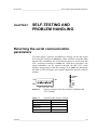
1
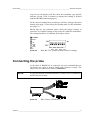
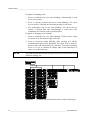
_________________________________________________________________________CONTENTS PTU200 Series Transmitters USER'S GUIDE M210195EN-A AUGUST 2001 VAISALA ___________________________________________________________________________I USER'S GUIDE_______________________________________________________________________ Table of contents CHAPTER 1 GENERAL INFORMATION ............................................................ 1 Safety.............................................................................................. 1 Warranty......................................................................................... 2 CHAPTER 2 PRODUCT DESCRIPTION............................................................. 3 Pressure measurement ................................................................ 3 Humidity and temperature measurement ................................... 4 CHAPTER 3 GETTING STARTED ...................................................................... 5 Mounting ........................................................................................ 5 Electrical connections .................................................................. 5 Connecting the probe ................................................................... 7 CHAPTER 4 COMMISSIONING .......................................................................... 9 Display and keypad....................................................................... 9 Operating modes......................................................................... 11 SMODE Selecting the sending mode ...................................... 11 Software settings ........................................................................ 12 SERI Serial bus settings .......................................................... 12 ECHO Setting the serial bus echo on/off ................................. 12 FORM Defining the output format............................................ 13 EFORM Defining the error output format................................. 14 DFORM Defining the display format ........................................ 15 PROMPT Setting the prompt outputting ON or OFF ............... 16 UNIT Setting the pressure and temperature units ................... 16 AVRG Setting the averaging time............................................ 17 INTV Setting the output interval ............................................... 18 ADDR Setting the transmitter address (for POLL mode)......... 18 SCOM User specific SEND command..................................... 19 PSTAB Setting the pressure stability indicator ........................ 20 PDMAX Setting the pressure difference limit........................... 20 KEYLOCK Setting the keyboard lock on/off ............................ 21 Hardware settings ....................................................................... 21 CHAPTER 5 OPERATING ................................................................................. 25 RUN and STOP modes................................................................ 25 R Starting the continuous output.............................................. 26 S Stopping the output .............................................................. 26 SEND Outputting a single message only................................. 27 RESET Resetting the transmitter............................................. 27 POLL mode .................................................................................. 27 SEND Outputting one single message .................................... 28 OPEN Setting a transmitter from POLL mode to STOP mode 29 CLOSE Setting a transmitter from STOP mode to POLL mode29 SEND mode.................................................................................. 30 CHAPTER 6 CALIBRATION AND ADJUSTMENT........................................... 31 Pressure ....................................................................................... 31 CORR Listing linear and multipoint pressure corrections ........ 32 LC Linear pressure corrections................................................ 33 II _____________________________________________________________________ M210195EN-A _________________________________________________________________________CONTENTS LCI Entering linear pressure corrections ..................................34 MPC Multipoint pressure corrections........................................35 MPCI Entering multipoint pressure corrections ........................36 CALD Storing the date of calibration ........................................37 Humidity........................................................................................38 Humidity adjustment .................................................................38 Temperature .................................................................................39 Offset ........................................................................................39 Gain ..........................................................................................40 TXCI Entering corrections for HMP45D and PT100 temperature measurement............................................................................40 V0XCI Entering corrections for HMP45A-P temperature measurement............................................................................41 CHAPTER 7 SELF-TESTING AND PROBLEM HANDLING.............................43 Returning the serial communication parameters.....................43 Diagnostic commands ................................................................44 ? Basic information on the transmitter settings .......................44 VERS Software version ............................................................45 SNUM Serial number................................................................45 ERRS Error message output ...................................................45 CHAPTER 8 TECHNICAL DATA .......................................................................47 Barometric pressure....................................................................47 Operating range........................................................................47 Accuracy class..........................................................................47 Humidity........................................................................................48 Temperature .................................................................................48 HMP45A-P & HMP45D.............................................................48 Pt100 sensor head....................................................................48 General..........................................................................................49 Mechanics.....................................................................................50 Transmitter body.......................................................................50 HMP45A-P and HMP45D .........................................................50 PT100 sensor head ..................................................................50 Weight.......................................................................................50 Dimensions ...............................................................................51 Transmitter body..................................................................51 HMP45A-P & HMP45D........................................................51 Pt100 sensor head ..............................................................52 Electromagnetic compatibility....................................................52 Accessories..................................................................................52 APPENDIX A OPTIONAL RS485/422 INTERFACE OF PTU200 TRANSMITTERS...........................................................................53 APPENDIX B ASHTECH PORT A/B 16 PIN CONNECTOR...............................56 APPENDIX C NMEA DATA FORMAT .................................................................58 GPS Commands...........................................................................59 Serial number ...........................................................................60 VAISALA __________________________________________________________________________ III CHAPTER 1_______________________________________________________ GENERAL INFORMATION CHAPTER 1 GENERAL INFORMATION Safety Throughout the manual important instructions regarding the safety considerations are focused as follows. WARNING Warning denotes a hazard. It calls attention to a procedure, practice, condition or the like, which, if not correctly performed or adhered to, could result in injury to or death of personnel. CAUTION Caution denotes a hazard. It calls attention to a procedure, practice, condition or the like, which, if not correctly performed or adhered to, could result in damage to or destruction of part or all of the product. NOTE Note highlights important information. It calls attention to an essential procedure, practice, condition or the like. VAISALA __________________________________________________________________________ 1 USER'S GUIDE_______________________________________________________________________ Warranty Vaisala hereby represents and warrants all Products manufactured by Vaisala and sold hereunder to be free from defects in workmanship or material during a period of twelve (12) months from the date of delivery save for products for which a special warranty is given. If any Product proves however to be defective in workmanship or material within the period herein provided Vaisala undertakes to the exclusion of any other remedy to repair or at its own option replace the defective Product or part thereof free of charge and otherwise on the same conditions as for the original Product or part without extension to original warranty time. Defective parts replaced in accordance with this clause shall be placed at the disposal of Vaisala. Vaisala also warrants the quality of all repair and service works performed by its employees to products sold by it. In case the repair or service works should appear inadequate or faulty and should this cause malfunction or nonfunction of the product to which the service was performed Vaisala shall at its free option either repair or have repaired or replace the product in question. The working hours used by employees of Vaisala for such repair or replacement shall be free of charge to the client. This service warranty shall be valid for a period of six (6) months from the date the service measures were completed. This warranty is however subject to following conditions: a) A substantiated written claim as to any alleged defects shall have been received by Vaisala within thirty (30) days after the defect or fault became known or occurred, and b) the allegedly defective Product or part shall, should Vaisala so require, be sent to the works of Vaisala or to such other place as Vaisala may indicate in writing, freight and insurance prepaid and properly packed and labelled, unless Vaisala agrees to inspect and repair the Product or replace it on site. This warranty does not however apply when the defect has been caused through a) normal wear and tear or accident; b) misuse or other unsuitable or unauthorized use of the Product or negligence or error in storing, maintaining or in handling the Product or any equipment thereof; c) wrong installation or assembly or failure to service the Product or otherwise follow Vaisala's service instructions including any repairs or installation or assembly or service made by unauthorized personnel not approved by Vaisala or replacements with parts not manufactured or supplied by Vaisala; d) modifications or changes of the Product as well as any adding to it without Vaisala's prior authorization; e) other factors depending on the Customer or a third party. Notwithstanding the aforesaid Vaisala's liability under this clause shall not apply to any defects arising out of materials, designs or instructions provided by the Customer. This warranty is expressly in lieu of and excludes all other conditions, warranties and liabilities, express or implied, whether under law, statute or otherwise, including without limitation ANY IMPLIED WARRANTIES OF MERCHANTABILITY OR OF FITNESS FOR A PARTICULAR PURPOSE and all other obligations and liabilities of Vaisala or its representatives with respect to any defect or deficiency applicable to or resulting directly or indirectly from the Products supplied hereunder, which obligations and liabilities are hereby expressly cancelled and waived. Vaisala's liability shall under no circumstances exceed the invoice price of any Product for which a warranty claim is made, nor shall Vaisala in any circumstances be liable for lost profits or other consequential loss whether direct or indirect or for special damages. 2 ____________________________________________________________________ M210195EN-A CHAPTER 2_______________________________________________________ PRODUCT DESCRIPTION CHAPTER 2 PRODUCT DESCRIPTION The PTU200 transmitter combines three measurement parameters: pressure, temperature and humidity. The applications of the PTU200 range from calibration laboratory environmental condition monitoring to laser interferometer active wavelength compensation and GPS meteorological measurements. The PTU200 transmitters are available with one or two pressure transducers. Three different kinds of sensor heads can be used with PTU200: HMP45A-P, HMP45D and Pt100. The PTU200 transmitters use a RS232 or RS485 (optional) serial interface and they are available also with a local display. In outdoor applications, it is recommended to use the PTU200MIK mounting kit with the PTU200 transmitters. In addition, a mounting tripod is available to support the PTU200MIK in temporary field installations. Pressure measurement The PTU200 series transmitters use a BAROCAP® silicon capacitive absolute sensor developed by Vaisala for barometric pressure measurement applications. The measurement principle of the PTU200 series digital transmitters is based on an advanced RC oscillator and three reference capacitors against which the capacitive pressure sensor and the capacitive temperature compensation sensor are continuously measured. The microprocessor of the transmitter performs compensation for pressure linearity and temperature dependence. VAISALA __________________________________________________________________________ 3 USER'S GUIDE_______________________________________________________________________ Humidity and temperature measurement The HMP45A-P and HMP45D probes are designed for the measurement of relative humidity and temperature. The humidity measurement is based on a capacitive thin film polymer sensor, HUMICAP180. The temperature measurement is based on resistive platinum sensors. Both the humidity and the temperature sensors are located at the tip of the probe and protected by a membrane filter. The HMP45A-P probe has the HUMICAP180 polymer sensor and the Pt 1000 resistive platinum sensor for RH and T measurements, respectively. The 20 metres cable of the HMP45A-P is connected to a board with a plug and thus the user can cut the cable to suitable length and reconnect it easily. The HMP45A-P and the HMP45D have a similar humidity output, but the temperature output is active in the HMP45A-P (voltage output 0-1V) and passive in the HMP45D (resistive output Pt 100). The HMP45D comes with a 3.5-meter connection cable. The cable is soldered directly to the board inside the transmitter. When the humidity measurement is not required, the PTU200 can be supplied with a small, high stability wire-type Pt100 temperature sensor head. 4 ____________________________________________________________________ M210195EN-A CHAPTER 3___________________________________________________________ GETTING STARTED CHAPTER 3 GETTING STARTED Mounting Choose a place, which represents the environment to be measured, and is as clean as possible. Air should circulate freely around the probe; it ensures that the sensor head and the ambient air are at the same temperature. NOTE For outdoor installation of the PTU200 transmitter, it is recommended to use a PTU200MIK mounting kit. For further information, please contact Vaisala or Vaisala distributor. Please take into a consideration that the pressure fitting supplied with the transmitter is not a static pressure head and that the transmitter cannot be used successfully as such in turbulent or high speed static wind conditions. NOTE The barometric pressure measurement accuracy quoted for the PTU200 series digital transmitters does not include any wind or air conditioning system measurement errors. Electrical connections PTU200 series transmitters have as a standard a RS 232C and as an option a RS485/422 serial interface. Connect the RS 232C serial interface and a power supply according to the following pin assignment. 5 43 21 9 8 76 FIGURE 3-1 9-pin female sub D-connector VAISALA __________________________________________________________________________ 5 USER'S GUIDE_______________________________________________________________________ TABLE 3-1 PIN 1 2 3 4 5 6 7 8 9 TABLE 3-2 PIN 1 2 3 4 5 6 7 8 9 Pin assignment for RS 232C/TTL serial output SIGNAL TX with diode TX/TXD/TXD inverted RX/RXD/RXD inverted external power on/off control ground for the RS 232C ground for supply voltage supply voltage (10...30 VDC) Pin assignment for optional RS 232C/485/422 SIGNAL TX with diode TX/TXD/TXD inverted RX/RXD/RXD inverted external power on/off control ground for the RS 232C RS 485/422 LO ground for supply voltage and TTL level serial interface RS 485/422 HI supply voltage (10...30 VDC) The factory settings of the PTU200 series transmitters are the following: TABLE 3-3 Baud rate Parity Data bits Stop bits Duplex Serial interface factory settings 9600 even 7 1 full duplex After having made the electrical connections, switch the power on, and the transmitter responds indicating its type and the software version. PTU200 / 1.01 > The transmitter is now ready to respond to any command available. 6 ____________________________________________________________________ M210195EN-A CHAPTER 3___________________________________________________________ GETTING STARTED At power-up, the display will first show the transmitter type and the software version. Then it switches to display the reading as defined with the DFORM command (page 9). Set the desired sending form according to software settings (described starting from page 12) and select the sending mode for the transmitter (see page 11). Should there be any problems please check the jumper settings in connector X15 and the settings in dip switch S1 inside the transmitter. The settings should be as indicated in the figure below. RX/RXD RXD ON TX TXD TXD OFF SW1 SW3 SW5 SW7 SW2 SW4 SW6 SW8 X15 FIGURE 3-2 S1 Basic RS 232C jumper and dip switch S1 settings Connecting the probe As the cable of HMP45A-P is connected via screw terminals the user can shorten the cable to desired length and reconnect it easily. The cable wires are connected as shown in FIGURE 3-3. NOTE It is not recommend to unsold and then re-sold the wires of HMP45D and PT100 sensor head. FIGURE 3-3 Wire colours of HMP45A-P. VAISALA __________________________________________________________________________ 7 USER'S GUIDE_______________________________________________________________________ FIGURE 3-4 Connecting the cable. Dimensions in mm (inches). 8 ____________________________________________________________________ M210195EN-A CHAPTER 4_____________________________________________________________COMMISSIONING CHAPTER 4 COMMISSIONING Display and keypad The optional LCD display has an on/off selectable backlight for better readability at any light conditions. The two rows of the display can be defined to indicate different kind of information. The keypad of the display cover can be used to inspect and change the parameters available. The format of the display is defined by using the serial command DFORM (see page 15). There are two rows containing 16 characters each; the user can define a maximum of 32 characters to be displayed, 16 characters on each row. The following fields in the display format can be used: pressure quantities (pressure, average, difference) three-hour pressure trend and pressure tendency code temperature quantity and relative humidity units error status and stability indicator number and text fields The following basic rules apply to the use of the keypad: 1. Use ENT key to acknowledge a new selection. 2. Use CL key to activate a parameter or unit to be changed or to revert to the original display. 3. Use arrow keys to make a selection between functional alternatives. Only the display contrast can be adjusted if the KEYLOCK is ON. The transmitter displays NO MODIFICATIONS ALLOWED message for a few seconds before reverting to the original display. It is also possible to inspect the settings of the transmitter although the KEYLOCK has been turned ON. VAISALA __________________________________________________________________________ 9 USER'S GUIDE_______________________________________________________________________ Example of changing units: 1. Press ENT and the text the ENT key (enter). UNIT starts blinking. Acknowledge it with 2. Press CL and the pressure unit in use starts blinking. Use arrow keys to choose a desired unit and acknowledge it with enter. 3. The temperature unit in use starts blinking. Use arrow keys to choose a desired unit and acknowledge it with enter. The transmitter now returns to the original display. Example of changing serial settings: 1. Press ENT and the text UNIT starts blinking. Choose the arrow keys and acknowledge with enter. SER by using 2. Press CL and BAUD starts blinking. After pressing ENT, all the available baud rates will be displayed. Use arrow keys to choose a desired value and acknowledge it with enter. PARI starts blinking. Press CL to exit or continue to change other serial parameters in same way as the baud rate. NOTE Note that modifications made using the keyboard will affect the serial interface settings, too. FIGURE 4-1 Available functions and selections of the local display 10 ___________________________________________________________________ M210195EN-A CHAPTER 4_____________________________________________________________COMMISSIONING Operating modes Select the desired sending mode for the transmitter. This is done with a command SMODE. SMODE Selecting the sending mode SMODE x <cr> where: x = STOP, RUN, SEND or POLL The SMODE command is used to set or inspect the sending mode of the transmitter. The PTU200 series transmitters have four sending modes: STOP, RUN, SEND and POLL. In STOP mode, after power-up the transmitter outputs its type and software version and then waits for further commands. In RUN mode, continuous outputting starts automatically from powerup. In SEND mode, a single message is automatically output after powerup. POLL mode allows the communication with multiple transmitters or other digital instruments connected to one serial bus. The transmitter does not echo in POLL mode. Examples: >smode <cr> Serial mode : STOP >smode run <cr> Serial mode : RUN >smode send <cr> Serial mode : SEND >smode poll <cr> Serial mode : POLL >smode stop <cr> Serial mode : STOP >reset<cr> NOTE Remember to give the RESET command to initialize the new sending mode. VAISALA _________________________________________________________________________ 11 USER'S GUIDE_______________________________________________________________________ Software settings SERI Serial bus settings SERI b p d s x <cr> where: b p (* = factory setting) = = baud rate (300...9600*...38400) parity (E = even*, O = odd, N = none) d = data bits (7* or 8) s = stop bits (1* or 2) x = duplex (F = full* or H = half) <cr> = carriage return is generated by the ENTER or RETURN key of the host computer The SERI command is used to set or inspect the serial bus settings of the transmitter. Examples: >seri <cr> 9600 E 7 1 F >seri 1200 N 8 1 H <cr> 1200 N 8 1 H >reset <cr> PTU200 / 1.01 > NOTE Always give the RESET command after the SERI command to activate the new serial bus settings. ECHO Setting the serial bus echo on/off ECHO x <cr> where: x = ON or OFF The ECHO command can be used to set or inspect the echoing condition of the transmitter. In OFF mode the transmitter does neither output the '>' prompt character nor echo the given commands. 12 ___________________________________________________________________ M210195EN-A CHAPTER 4_____________________________________________________________COMMISSIONING Examples: >echo <cr> Echo > >echo off <cr> Echo : ON : OFF FORM Defining the output format FORM <cr> The FORM command can be used to set or inspect the output format of the transmitter. The maximum length of FORM is 80 characters. The user can define the following fields into the output format: amount of decimals pressure trend *) pressure tendency give number of decimals before a quantity. Giving 4.2 before the pressure quantity outputs a reading with the following form: 1013.12 P1, P2, P (average), PD (difference) TRE (three-hour trend) A (three-hour tendency) temperature quantity of PT100 and HMP45D sensor heads *) T temperature quantity of HMP45A-P *) TH pressure quantities relative humidity units serial number of the transmitter error status stability indicator checksums number fields text fields CR LF TAB nnn ASCII code RH U, UU, UUU, UUUU, UUUUU SN ERR (three characters) OK (uses three characters) CS2, CS4 CSX n.m where: n = 0 - 9, m = 0 - 9 within “ “ characters \ r or #r \ n or #n \ t or #t \ nnn or # nnn (cannot be 000) *) The PTU200 transmitter cannot output + sign for pressure trend or temperature reading; a space is output instead. VAISALA _________________________________________________________________________ 13 USER'S GUIDE_______________________________________________________________________ Example of setting the output format: >form P1 " " UUU " " T " " UU " " RH " " UUU \r \n ? 4.1 P " " UUU " " "Tend" " " 1.0 A " " 3.1 T UU " " 3.0 RH UUU \r \n >send 1007.9 hPa Tend 7 24.9'C 28%RH > Inspecting the output format: >form P1 " " UUU " " T " " UU " " RH " " UUU \r \n ?<esc> Use ESC-key to abort without changing the settings. EFORM Defining the error output format EFORM <cr> The EFORM command can be used to define a user specific error output format for the serial line. In case of an error, the transmitter outputs the defined format instead of *****. Example of an EFORM definition: >eform <cr> ? "ERROR" \r \n <cr> >send 1007.8 hPa OK (correct operation) >send <cr> ERROR (incorrect operation) > Any previous EFORM definition may be removed with the following command: >eform * <cr> > 14 ___________________________________________________________________ M210195EN-A CHAPTER 4_____________________________________________________________COMMISSIONING DFORM Defining the display format DFORM <cr> The DFORM command is used to define the format for the optional LCD display. There are two rows containing 16 characters each. The user can define the following fields into the display format: pressure quantities P1, P2, P (average), PD (difference) TRE (three-hour trend) A (three-hour tendency) pressure trend *) pressure tendency temperature quantity of PT100 and HMP45D sensor heads *) T temperature quantity of HMP45 TH relative humidity RH units U, UU, UUU, UUUU, UUUUU serial number of the transmitter SN error status ERR (three characters) stability indicator OK (uses three characters) number fields n.m where: n = 0 - 9, m = 0- 9 text fields within “ “ characters *) The PTU200 transmitter cannot output + sign for pressure trend or temperature reading; a space is output instead. Any previous DFORM definition may be removed and the original factory setting restored with the following command: >dform * <cr> > Example of setting the display format to show pressure, stability indicator, pressure trend and pressure tendency: >dform <cr> 4.2 P " " UUUUU OK \r \n ? " " 4.2 P " " UUU OK " trend " 2.1 TRE " " UUU " " A <cr> > The display will look similar to the following: VAISALA _________________________________________________________________________ 15 USER'S GUIDE_______________________________________________________________________ The PTU200 transmitter will show * instead of numeric values for pressure trend and pressure tendency for three hours from power-up. In case of error, the relevant error message will automatically appear on the display. In this case, any other information defined using the DFORM command will be replaced with an error message. PROMPT Setting the prompt outputting ON or OFF PROMPT x where: x= ON or OFF >PROMPT<cr> Prompt : ON >PROMPT OFF<cr> Prompt : OFF send<cr> 1007.9 hPa Tend 7 24.9 'C PROMPT ON<cr> Prompt : ON > 28 %RH UNIT Setting the pressure and temperature units UNIT x <cr> where (* = factory setting) x = hPa*, kPa, Pa, bar, mbar, inHg, mmHg, torr, mmH2O, psia, C*, F This command is used to set and inspect the pressure and temperature unit. Example of changing the pressure and temperature units: >unit <cr> P unit : hPa T unit : 'C >unit C <cr> >send 1018.33 hPa >unit torr <cr> P unit : torr T unit : 'C >unit F <cr> >send 763.84 torr > 24.19 'C 75.62 'F 32.96 %RH 32.89 %RH 16 ___________________________________________________________________ M210195EN-A CHAPTER 4_____________________________________________________________COMMISSIONING AVRG Setting the averaging time AVRG x <cr> where: x = 1 ... 600 (seconds) The AVRG command is used to set and inspect the averaging time during which the individual measurement samples are integrated to get an averaged reading. The averaging time is the total averaging time of the transmitter. In case of two internal pressure transducers, the defined averaging time is divided by three to get an averaging time for each pressure transducer. The third transducer is the VMT for measuring RH/T. Note that if the averaging time is defined to be long, the settling time at power-up will be long, too. The output reading is a running average pressure reading. The measurement is updated in normal measurement mode approximately every 1 to 4 seconds, depending on the AVRG setting. A minimum of one-second averaging time is recommended per each pressure transducer. These selections are used as the factory setting averaging times. Example of setting the averaging time to 60 seconds (WMO averaging time for barometric pressure measurement): >avrg <cr> Averaging time: > >avrg 60 <cr> Averaging time: > 1.0 ?<cr> 60.0 VAISALA _________________________________________________________________________ 17 USER'S GUIDE_______________________________________________________________________ INTV Setting the output interval INTV x y <cr> where: x = output interval (0...255) y = unit (s, min, h) This command is used to set and inspect the output interval. The R command is used to start the outputting. Examples: NOTE >intv <cr> Output intrv. : > 0 s >intv 10 s <cr> Output intrv. : >r <cr> 10 s In case of the half duplex RS 485/422 serial communication, the user is requested to set the interval time to one second or more. This enables an interruption of outputting, if the R command is given by mistake. ADDR Setting the transmitter address (for POLL mode) ADDR x <cr> where: x = the address (0 ... 99) This command is used to set and inspect the address of the transmitter for the POLL mode. The address feature is important when multiple transmitters are connected to one RS232C interface or when a transmitter is used on an RS485/422 serial interface. Example of setting the address to 7: >addr 7 <cr> Address > : 7 18 ___________________________________________________________________ M210195EN-A CHAPTER 4_____________________________________________________________COMMISSIONING A new address replaces the previous one. Always set the address to 0 when no address is needed: >addr 0 <cr> Address > NOTE : 0 If the transmitter is not closed in the POLL mode, it will respond to any SEND command despite of the address. The transmitter has to be set to POLL mode and then closed with CLOSE command (see Chapter POLL mode). SCOM User specific SEND command SCOM <cr> This command is used to define a user specific SEND command for one message output. The standard SEND command of the transmitter will always function normally whatever the SCOM definition may be. The new command must be defined within “ “ signs, then some end characters also can be defined. Note that the SCOM command is case sensitive. It is in fact recommended to use the opposite case characters for SCOM definition to avoid incocsistency with other commands. Note also that the PTU200 does not react on <eot> at the end of a command. Example of setting a P (note the upper case character in comparison to the rest of the lower case characters) command for one message output: >scom <cr> ? "P" \ r <cr> >P <cr> 1020.30 hPa > Example of defining a similar command without an end character: >scom <cr> "P" \r ? "P" <cr> >P1020.30 hPa > Any previous SCOM definition may be removed with the following command: >scom * <cr> > VAISALA _________________________________________________________________________ 19 USER'S GUIDE_______________________________________________________________________ PSTAB Setting the pressure stability indicator PSTAB x <cr> where: x = pressure reading (in current unit) The PSTAB command is used to define the pressure stability indicator reflecting maximum allowed pressure difference between two successive averaged measurements. The user has to also define the FORM command to include the "OK" stability indicator field. The factory setting for the stability indicator level is 0.5 hPa. >pstab 0.5 <cr> Stab. level : >form 0.50 hPa ? 4.2 P " " UUU " " OK \r \n >send <cr> 1020.30 hPa OK (accepted) >send <cr> 1020.30 hPa (rejected) > PDMAX Setting the pressure difference limit PDMAX x <cr> where: x = pressure reading This command is used to define the maximum pressure difference between the pressure readings from two pressure transducers (P1 and P2). If the defined value is exceeded, the relevant digits in the ERR field will change from 0 to 1. More than one ´1´ in the ERR field indicates that the pressure reading output is not reliable. For an acceptable measurement crucial conditions are: - two transducers: P high - P low ≤ Pdmax The factory setting for Pdmax is 1 hPa. 20 ___________________________________________________________________ M210195EN-A CHAPTER 4_____________________________________________________________COMMISSIONING Example of setting the limit to 0.5 hPa: >pdmax <cr> Pd max > : 1.000 ? 0.5 <cr> Example of exceeding the Pdmax limit: >form <cr> 4.2 P " " UUUU \r \n ? 4.2 P1 " " P2 " " P " " UUU " " ERR \r \n <cr> >send <cr> 1020.30 1020.32 1020.31 hPa 00 >send <cr> 1020.30 1022.30 1021.30 hPa 11 > Please use the ERRS command to analyze problems. KEYLOCK Setting the keyboard lock on/off KEYLOCK x <cr> where: x = ON or OFF The KEYLOCK command is used to set or inspect the keypad lock condition of the display cover keypad. The PTU200 transmitters with display cover are supplied with the keypad locked (KEYLOCK OFF). It is thus possible to inspect the settings but not to change them. With the keypad locked the settings can be inspected but not changed. Example: >keylock on <cr> Keylock : ON > If anyone tries to change the settings using the keypad with the KEYLOCK ON, the transmitter will display NO MODIFICATIONS ALLOWED for a few seconds and then returns to the original display. Hardware settings Inside the transmitter, there is a connector X15 (see FIGURE 4-2) and a dip switch S1 (see FIGURE 4-3). These are used to make the main hardware settings of the PTU200. VAISALA _________________________________________________________________________ 21 USER'S GUIDE_______________________________________________________________________ With the connector X15 the user can select the RS 232C (RX, TX) or TTL levels for serial communication. With TTL levels, the user also has phase alternatives available for both input (RXD, RXD inverted) and output (TXD, TXD inverted). RX/RXD RXD TX TXD TXD X15 FIGURE 4-2 RS 232C/TTL level and phase selections The half duplex two-wire RS485/422 serial interface of the PTU200 does not require any hardware settings to be made to the transmitter. See page 53 for quick reference information on how to use the RS485/422 interface of the PTU200 series digital transmitters. Normally, the dip switch S1 settings are all OFF as in FIGURE 4-3 ON S1 OFF SW1 SW3 SW5 SW7 SW2 SW4 SW6 SW8 FIGURE 4-3 Basic dip switch S1 settings An external power control can be used to switch the PTU200 transmitter ON/OFF. The control is activated with the switch SW2 in position ON as shown in FIGURE 4-4. The TTL signals are: 0VDC OFF and 5VDC ON. ON S1 OFF SW1 SW3 SW5 SW7 SW2 SW4 SW6 SW8 FIGURE 4-4 External power control ON 22 ___________________________________________________________________ M210195EN-A CHAPTER 4_____________________________________________________________COMMISSIONING Summarized settings of the dip switch S1. TABLE 4-1 SW1 SW2 SW3 SW4 SW5 SW6 SW7 SW8 OFF OFF ON OFF OFF ON OFF OFF OFF OFF ON not used external power control OFF (TTL: 0 VDC) external power control ON (TTL: 5 VDC not used memory write DISABLE memory write ENABLE not used not used not used factory settings OFF / user settings ON factory settings ON (9600, E, 7, 1, F) VAISALA _________________________________________________________________________ 23 CHAPTER 5________________________________________________________________ OPERATING CHAPTER 5 OPERATING Only a few commands are needed to operate a PTU200 transmitter in the RUN, STOP and POLL modes. In the SEND mode, no commands are needed. In the RUN or STOP modes, the commands R, S and SEND can be used. The user may also use his own SEND command if he has previously specified one using the SCOM command. In the POLL mode, the transmitter responds to a SEND command only if it includes the address. OPEN and CLOSE commands are also available for temporary communication with one single transmitter. In the SEND mode, no commands are needed. The transmitter will automatically output one message at power-up, or when triggering the transmitter on using pin 4. RUN and STOP modes summarizes the commands that are used in the RUN and STOP modes. In addition, the user may use his own SEND command if he has previously specified one with the SCOM commissioning command. The commands are not case sensitive except for the SCOM command. TABLE 5-1 TABLE 5-1 Commands used in RUN and STOP modes Function starting output stopping output single message output resetting the transmitter Command R S SEND RESET VAISALA _________________________________________________________________________ 25 USER'S GUIDE_______________________________________________________________________ R Starting the continuous output R <cr> This command is used to start continuous outputting in the STOP and RUN modes and after setting the output interval (see page and 18). Example (in STOP mode): >reset <cr> PTU200 / 1.01 >r <cr> 1013.25 hPa 22.9 %RH 22.4 'C 1013.25 hPa 22.9 %RH 22.4 'C 1013.25 hPa 22.) %RH 22.4 'C ... Example of restarting the outputting (in RUN mode): >SMODE<cr> Serial mode : RUN >RESET<cr> 1009.1 hPa 42.4 %RH 24.2 1009.1 hPa 42.4 %RH 24.2 ... S<cr> (text invisible) >R<cr> 1009.2 hPa 42.5 %RH 24.2 1009.1 hPa 42.5 %RH 24.2 ... 'C 'C 'C 'C S Stopping the output S <cr> This command is used to stop the continuous outputting (activated with power-up or reset in RUN mode or using the R command). Example: >r <cr> 1013.25 hPa 22.9 %RH 22.4 'C 1013.25 hPa 22.9 %RH 22.4 'C 1013.25 hPa 22.9 %RH 22.4 'C s <cr> (text invisible) > 26 ___________________________________________________________________ M210195EN-A CHAPTER 5________________________________________________________________ OPERATING SEND Outputting a single message only SEND <cr> This command is used to output one message at a time in the STOP and RUN modes. >reset <cr> PTU200 / 1.01 >send <cr> 1013.25 hPa 22.9 %RH 22.4 'C > The user may also use his own one-message command if he has previously specified one using the SCOM command (see Chapter on page 11). RESET Resetting the transmitter RESET <cr> The RESET command is used to reset the transmitter. All software settings remain in the memory after reset or any power failure. The RESET command must always be given if the serial bus settings, DIP switch settings or the operating mode of the transmitter have been changed. Example: >reset <cr> PTU200 / 1.01 > POLL mode TABLE 5-2 Commands used in RUN and STOP modes Function single message output opening a transmitter closing a transmitter Command SEND OPEN CLOSE VAISALA _________________________________________________________________________ 27 USER'S GUIDE_______________________________________________________________________ The POLL mode is used when several PTU200 series transmitters are connected to one RS232C serial interface. It is also used when several intelligent transmitters are connected to a half duplex RS 485/422 serial interface. In the POLL mode, the transmitter must have a specific address so that the host system is able to direct the outputting commands to the particular transmitter. The addressable SEND command is used to ask for a single message output from the transmitter. The OPEN command can be used to open a single transmitter temporarily to STOP mode. The CLOSE command will restore the POLL mode. SEND Outputting one single message SEND a <cr> where: a = the address of the transmitter (0...99) This command is used to output one message from the transmitter in the POLL mode (see SMODE command). Example: >addr 7 <cr> Address : >smode poll <cr> Serial mode : POLL >close <cr> line closed send 7 <cr> 1013.25 hPa 7 (text invisible) 28 ___________________________________________________________________ M210195EN-A CHAPTER 5________________________________________________________________ OPERATING OPEN Setting a transmitter from POLL mode to STOP mode CLOSE Setting a transmitter from STOP mode to POLL mode OPEN a <cr> CLOSE <cr> where: a = the address of the transmitter (0...99) These commands are used to set a transmitter temporarily to STOP mode and back to POLL mode again. The OPEN command is useful when several transmitters are connected to one serial bus and communication with a single transmitter is needed. The CLOSE command is a global command and requires no address. The PTU200 series transmitters must always be closed after the POLL mode selection. The RESET command and powering-up will close the PTU200 series transmitters automatically. >addr 7 <cr> Address : >smode poll <cr> Serial mode : POLL >close <cr> 7 <cr> line closed Example of opening and closing a transmitter with address 7: open 7 <cr> PTB (text invisible) 7 line opened for operator commands > Any commands (except for the ? command) can now be used for the transmitter with address 7 without affecting other transmitters with different addresses connected to the same serial interface. However, if the RESET command is given or the transmitter is powered-up, the transmitter will automatically return to the POLL mode. Example of closing a transmitter: >close <cr> line closed VAISALA _________________________________________________________________________ 29 USER'S GUIDE_______________________________________________________________________ SEND mode In the SEND mode, the transmitter will automatically output one message at power-up or when triggering the transmitter on using pin 4 of the transmitter. The trigger signal must be a TTL level signal. TTL HIGH (5 VDC) turns the transmitter ON and TTL LOW (0 VDC) turns the transmitter OFF. Examples of outputting with the prompt (ECHO ON) and without the prompt (ECHO OFF): >echo <cr> Echo : ON >smode send <cr> Serial mode : SEND >reset <cr> 1013.25 hPa > >echo off <cr> Echo : reset <cr> 1013.25 hPa OFF (text invisible) Example of outputting a minimum amount of (six) characters by excluding the <cr> and <lf> characters, the pressure unit and the decimal point with the FORM command: >form <cr> 4.2 P " " UUUU \r \n ? 6.0 P <cr> >unit Pa P unit : Pa >smode send <cr> Serial mode : SEND >echo off <cr> Echo : OFF reset <cr> 101325 or (power-up) 101325 (text invisible) 30 ___________________________________________________________________ M210195EN-A CHAPTER 6_______________________________________________ CALIBRATION AND ADJUSTMENT CHAPTER 6 CALIBRATION AND ADJUSTMENT Pressure The user can select a simple offset or a two-point offset and gain adjustment and use the LCI command for adjustment of pressure transducer. The MPCI command is used for the more sophisticated multipoint correction capability at up to eight pressure levels. Check first what linear corrections the transmitter is currently using before attempt to readjust the transducer. As the previous linear corrections will disappear when new linear corrections are input, the user has to take into account the previous linear corrections when deciding about the new ones. NOTE Entering new linear or multipoint corrections will always cancel the previous corrections. It is advisable to write down the previous linear and multipoint corrections so that they will not be lost by mistake. Entering new linear or multipoint corrections or changing their status will also automatically cancel the date of calibration of the transmitter (see CALD command). TABLE 6-1 Adjustment and calibration commands Function Command listing corrections CORR linear corrections on/off LC ON/OFF multipoint corrections on/off MPC ON/OFF entering multipoint corrections MPCI calibration date CALD The linear and multipoint corrections are protected by switch SW4 (see figure 6.2). The switch SW4 is normally in write DISABLE position (OFF) and the user must change it to write ENABLE position VAISALA _________________________________________________________________________ 31 USER'S GUIDE_______________________________________________________________________ (ON) to be able to enter new linear and multipoint corrections to the transmitter. ON S1 OFF SW1 SW3 SW5 SW7 SW2 SW4 SW6 SW8 FIGURE 6-1 NOTE Switch SW4 in write ENABLE position (ON) Always remember to return the switch SW4 to write DISABLE position (OFF). CORR Listing linear and multipoint pressure corrections CORR <cr> The CORR command is used to indicate the status of linear and multipoint pressure corrections. In case the status is ON, the corrections and valid date of calibration are listed. The listing varies according to the number of transducers in the transmitter. The transmitter lists * in the second column if there exists only one pressure transducer in the transmitter. Example of the listing of a transmitter with one pressure transducer: >corr Linear adjustments ON Reading Correction Reading Correction 500.010 0.120*******.**********.*** 1100.320 0.150*******.**********.*** Multipoint adjustments ON Reading Correction Reading Correction 499.660 -0.110*******.**********.*** 599.110 -0.080*******.**********.*** 698.580 -0.060*******.**********.*** 800.950 -0.030*******.**********.*** 900.400 0.010*******.**********.*** 947.200 0.020*******.**********.*** 999.840 0.050*******.**********.*** 1099.090 0.070*******.**********.*** 32 ___________________________________________________________________ M210195EN-A CHAPTER 6_______________________________________________ CALIBRATION AND ADJUSTMENT Transducer 2 CORRECTIONS: TXD0,TXD1,TXD2 : V0XD0,V0XD1,V0XD2: V1XD0,V1XD1,V1XD2: -0.12000 0.00000 0.00000 Calibration date > 1.00000 1.00000 1.00000 0.00000 0.00000 0.00000 1998-12-11 LC Linear pressure corrections LC x <cr> where: x = ON or OFF The LC command is used to activate or deactivate the linear offset or offset/gain pressure corrections. Plain command LC outputs the linear corrections in use. The linear corrections are protected with switch SW4 (see FIGURE 6-1) Turn the switch SW4 to write ENABLE position (ON) to be able to turn the linear corrections on or off. NOTE Changing the linear corrections on or off will automatically cancel the date of calibration of the transmitter. The listing varies according to the number of pressure transducers. Example of linear adjustments performed on a transmitter with two transducers: >lc off <cr> Linear adj. : OFF >lc on <cr> Linear adj. : ON >lc <cr> Reading Correction 1013.250 -0.100 1013.250 -0.100 > NOTE Reading Correction 800.000 0.050 1000.000 -0.020 Always remember to return the switch SW4 to write DISABLE position (OFF). VAISALA _________________________________________________________________________ 33 USER'S GUIDE_______________________________________________________________________ LCI Entering linear pressure corrections LCI n <cr> where: n = number of the pressure transducer (1 or 2) The LCI command is used to enter new linear offset and offset/gain pressure corrections to the transmitter. Note that the linear corrections are given to each pressure transducer separately. Entering new linear corrections is protected by switch SW4. Turn the switch SW4 to write ENABLE position (ON) to be able to enter new linear and multipoint corrections to the transmitter. Deactivate the previous corrections by using the LC OFF. Precalibration of the transmitter then gives the required new corrections. NOTE The new linear corrections will always cancel the previous corrections as well as the valid date of calibration of the transmitter (see CALD command). Activate the new linear corrections with the LC ON command. Use ESC to abort without executing the command. In the following, an example of performing an offset adjustment for pressure transducer P1 and an offset and gain adjustment for pressure transducer P2 is given. >lc off <cr> Linear adj. : OFF >lci 1 <cr> P1 1. reading ? 1013.25 <cr> correction ? -0.1 <cr> P1 2. reading ? <cr> >lci 2 <cr> P2 1. reading ? 800.00 <cr> correction ? 0.05 <cr> P2 2. reading ? 1000.00 <cr> correction ? -0.02 <cr> >lc on <cr> Linear adj. : ON Reading Correction Reading Correction 1013.250 -0.100 800.000 0.050 1013.250 -0.100 1000.000 -0.020 > NOTE Always remember to return the switch SW4 to write DISABLE position (OFF). 34 ___________________________________________________________________ M210195EN-A CHAPTER 6_______________________________________________ CALIBRATION AND ADJUSTMENT MPC Multipoint pressure corrections MPC x <cr> where: x = ON or OFF The MPC command is used to activate or deactivate the multipoint corrections. Plain command MPC outputs the corrections in use. The multipoint corrections are protected with switch SW4 (see FIGURE 6-1). Turn the switch SW4 to write ENABLE position (ON) to be able to turn the multipoint corrections on or off. NOTE Changing the multipoint corrections on or off will automatically cancel the previous date of calibration of the transmitter (see CALD command). Example of multipoint adjustments performed on a transmitter with one pressure transducer: >mpc off <cr> Multipoint adj: OFF >mpc on <cr> Multipoint adjustments ON >mpc<cr> Reading Correction Reading Correction 499.660 -0.110*******.**********.*** 599.110 -0.080*******.**********.*** 698.580 -0.060*******.**********.*** 800.950 -0.030*******.**********.*** 900.400 0.010*******.**********.*** 947.200 0.020*******.**********.*** 999.840 0.050*******.**********.*** 1099.090 0.070*******.**********.*** Multipoint adj: ON > NOTE Always remember to return the switch SW4 to write DISABLE position (OFF). VAISALA _________________________________________________________________________ 35 USER'S GUIDE_______________________________________________________________________ MPCI Entering multipoint pressure corrections MPCI n <cr> where: n = number of the pressure transducer (1 or 2) The MPCI command is used to enter new multipoint corrections to the transmitter. Note that the user must give the multipoint corrections to each pressure transducer separately. Turn the switch SW4 to write ENABLE position (ON) to be able to enter new linear and multipoint corrections to the transmitter. Deactivate the previous corrections first using the LC OFF and/or MPC OFF commands. Precalibration of the transmitter then gives the required corrections. When entering new multipoint corrections, always start at the lowpressure end and then go up the pressure range. NOTE The new multipoint corrections will always cancel the previous corrections as well as the valid date of calibration of the transmitter (see CALD command). Use ESC to abort without executing the command. The new multipoint corrections are activated with the MPC ON command. In the following, an example of performing a multipoint adjustment for pressure transducer P1 is given. >lc off <cr> Linear adj. : >mpc off <cr> Multipoint adj: >mpci 1 <cr> P1 1. reading correction P1 2. reading correction P1 3. reading correction P1 4. reading correction P1 5. reading OFF OFF ? ? ? ? ? ? ? ? ? 499.72 <cr> -0.07 <cr> 599.20 <cr> -0.08 <cr> 698.71 <cr> -0.01 <cr> 801.12 <cr> -0.01 <cr> 900.61 <cr> 36 ___________________________________________________________________ M210195EN-A CHAPTER 6_______________________________________________ CALIBRATION AND ADJUSTMENT correction 6. reading correction P1 7. reading correction P1 8. reading correction >mpc on <cr> Multipoint adj: > P1 NOTE ? ? ? ? ? ? ? -0.03 <cr> 947.42 <cr> -0.02 <cr> 1000.10 <cr> -0.04 <cr> 1099.58 <cr> -0.04 <cr> ON Always remember to return the switch SW4 to write DISABLE position (OFF). CALD Storing the date of calibration CALD yyyy-mm-dd <cr> This command is used to store the date of calibration in the memory of the transmitter. Example: >cald <cr> Calibration date >cald 1997-01-01 <cr> Calibration date > ????-??-?? 1997-01-01 Changing the status (ON/OFF) of the linear or multipoint corrections or entering new linear or multipoint corrections will automatically cancel the date of calibration. NOTE Always remember to return the switch SW4 to write DISABLE position (OFF). VAISALA _________________________________________________________________________ 37 USER'S GUIDE_______________________________________________________________________ Humidity Calibration of the HMP45A-P/D probes should be performed at regular intervals, depending on the conditions of use and desired accuracy. The recommended calibration interval is one year. FIGURE 6-2 D T pull the probe head off the handle W The HMP45A-P/D probes are easy to maintain, calibrate and adjust. The probe consists of a probe head and a handle with cable. All calibration electronics are in the probe head, which can be disconnected from the handle without disconnecting the wires. The probe heads are interchangeable. adjustment trimmers: W = wet D = dry (T for factory use only!) Adjustment trimmers and probe head connection/ disconnection Humidity adjustment For a high-accuracy two-point adjustment, use a Vaisala HMK15 or HMK13B calibrator and saturated salt solutions as described in the respective manuals. If there is no local display, read the outputs via the serial line. Leave the calibrator and the probe head in the same space for at least four hours so that their temperatures have time to equalize. Unscrew the plastic grid of the probe. The adjustment is done first for the dry end and then for the wet end with trimmer potentiometers marked “D” (dry, <50 %RH) and “W” (wet, >50 %RH). The potentiometers are located under a protective plug; see FIGURE 6-2. Use a ceramic screwdriver with 2.5 mm blade for adjusting the potentiometers. Note: if zero point is adjusted in Nitrogen (N2), the minimum output signal of 0.008 V corresponds to a relative humidity of 0.8 %RH. TABLE 6-2 Temperature LiCl NaCl K2SO4 Greenspan’s calibration table °C %RH %RH %RH 15 *) 75.6 97.9 20 11.3 75.5 97.6 25 11.3 75.3 97.3 30 11.3 75.1 97.0 35 11.3 74.9 96.7 *) Do not use or store the LiCl solution in temperatures below +18°C as its humidity equilibrium may change permanently 38 ___________________________________________________________________ M210195EN-A CHAPTER 6_______________________________________________ CALIBRATION AND ADJUSTMENT As the D (dry) and W (wet) adjustments may affect each other, check again the humidity reading at the low end. If needed repeat the procedure in low and high ends until the reading is correct. Temperature The temperature channels of PTU200 transmitters are very stable and the probes have been calibrated and adjusted at the factory. Unless there is a strong reason to believe that the adjustments have changed, DO NOT perform a temperature adjustment. This is a very demanding procedure and requires extremely accurate references. Furthermore, it is important to allow enough time for the stabilization during calibration. If for some reason, it is necessary to perform the temperature adjustment, follow attentively the instructions given below. NOTE The temperature channel has to be calibrated if the probe head has been changed. The temperature adjustment can be done via the serial line using linear offset and gain corrections. Entering any corrections is protected by switch SW4. Turn it to write ENABLE position (ON) to be able to enter new offset and gain corrections. NOTE If there is need for an adjustment, check first whether there exist any previously set corrections. Before entering new corrections, it is recommended to set the offset to 0 and the gain to 1. Then measure the temperature again at two reference points, and calculate the new offset and gain corrections. Offset It is recommended to perform the one-point offset correction in temperature, which is close to average measurement temperature. The offset can be calculated by using equation 6-1. Offset = Tref − Tmeas (6-1) where: Tref = T measured with an accurate reference thermometer Tmeas = T measured with PTU200 VAISALA _________________________________________________________________________ 39 USER'S GUIDE_______________________________________________________________________ Example: Tref = 23.15°C Tmeas = 23.28°C Offset = -0.13°C Gain The gain correction can be calculated with the equation 6-2. It is reasonable to use the low (T1) and the high (T2) end of needed temperature range. Gain = 1 + where: Tref1 Tref2 Tmeas1 Tmeas2 (T ref 1 − Tmeas 1 ) − (Tref 2 − Tmeas 2 ) Tmeas1 − Tmeas 2 (6-2) = measured with a reference thermometer at temperature T1 = measured with a reference thermometer at temperature T2 = measured with PTU200 at temperature T1 = measured with PTU200 at temperature T2 Example: Tref1 = -14.97°C and Tmeas1 = -14.90°C Tref2 = +30.12°C and Tmeas2 =+30.29°C Gain = 0.99779 Offset = Tref2 -Gain*Tmeas2 = -0.10 T = 0.99779 * 30.29°C - 0.10 = 30.12°C TXCI Entering corrections for HMP45D and PT100 temperature measurement TXCI x where: x= 2 if there is one pressure transducer installed 3 if there is two pressure transducers installed The TXCI command is used to enter new offset and offset/gain corrections for temperature measurement of HMP45D and PT100. 40 ___________________________________________________________________ M210195EN-A CHAPTER 6_______________________________________________ CALIBRATION AND ADJUSTMENT >txci TXD0 TXD1 TXD2 > : -1.199999971E-01 ? -0.10<cr> (offset) : 1.000000000E+00 ? 0.99779<cr> (gain) : 0.000000000E-01 ?<cr> (factory use only) The factory setting TXD2 is passed by pressing enter. Use ESC to abort without executing the command. Reset the transmitter to activate the given corrections. NOTE Always remember to return the switch SW4 to write DISABLE position (OFF). V0XCI Entering corrections for HMP45A-P temperature measurement V0XCI x where: x = 2 if there is one pressure transducer installed 3 if there is two pressure transducers installed The V0XCI command is used to enter new offset and offset/gain corrections for temperature measurement of HMP45A-P. Entering new corrections is protected by switch SW4. Turn it to write ENABLE position (ON) to be able to enter new offset/gain corrections. The factory setting V0XD2 is passed by pressing enter. Use ESC to abort without executing the command. Reset the transmitter to activate the given corrections. In the following, an example of performing an offset and gain adjustment: >V0XCI 2 V0XD0 : V0XD1 : V0XD2 : > NOTE 0.000000000E-01 ? -0.10<cr> 1.000000000E+00 ? 0.99778<cr> 0.000000000E-01 ?<cr> Always remember to return the switch SW4 to write DISABLE position (OFF). VAISALA _________________________________________________________________________ 41 CHAPTER 7____________________________________________ SELF-TESTING AND PROBLEM HANDLING CHAPTER 7 SELF-TESTING AND PROBLEM HANDLING Returning the serial communication parameters To restore factory software and hardware settings, set the dip switch S1 on the CPU board as in FIGURE 7-1. Other switches except the SW8 must be OFF. In addition, the serial interface has to be set for basic RS 232C operation according to FIGURE 7-1. With these selections, one single transmitter can be operated through the RS 232C serial interface using factory serial bus settings as in TABLE 7-1. Returning the SW8 to OFF will restore the original, application specific software settings. RX/RXD RXD ON S1 OFF SW1 SW3 SW5 SW7 SW2 SW4 SW6 SW8 TX TXD TXD FIGURE 7-1 X15 Factory settings for the dip switch S1 and Basic RS 232C settings TABLE 7-1 Serial interface factory settings Baud rate Parity Data bits Stop bits Duplex 9600 even 7 1 full duplex VAISALA _________________________________________________________________________ 43 USER'S GUIDE_______________________________________________________________________ Diagnostic commands The PTU200 series digital transmitters respond to a set of diagnostic commands, which are useful for analyzing the basic settings and general operation of the transmitters. The diagnostic commands are listed in TABLE 7-2 Diagnostic commands Function basic information on settings software version serial number outputting error messages Command ? VERS SNUM ERRS ? Basic information on the transmitter settings ? <cr> The ? command lists the basic information of the transmitter. >? Software version Serial number Configuration Linear adjustments Multipoint adjustments Calibration date Baud Parity Data Stop Dpx Echo Sending mode Address Output interval Output format Error output format SCOM format Pressure unit Temperature unit Transducer 1: TYPE: PMT Transducer 2: TYPE: VMT Transducer 3: TYPE: NONE > NOTE PTU200 / 1.02 T5030004 12 ON ON 1999-03-12 9600 E 7 1 F ON STOP 0 3 s 4.1 P " " UUU " " 2.1 RH " " UUU #r #n hPa 'C Use this command only for one transmitter at a time. Any PTU200 series transmitter will always respond to ?-command whatever its settings are, provided that the serial interface settings are correct. 44 ___________________________________________________________________ M210195EN-A CHAPTER 7____________________________________________ SELF-TESTING AND PROBLEM HANDLING VERS Software version VERS <cr> The VERS command is used to output the software version of the transmitter. >vers <cr> PTU200 / 1.01 > SNUM Serial number SNUM <cr> The SNUM command is used to output the serial number of the transmitter. >snum CPU serial TR1 serial TR2 serial TR3 serial CTR1 serial CTR2 serial CTR3 serial > no no no no no no no : T2210005 : 0 : 0 : 0 : 0 : 0 : 0 ERRS Error message output ERRS <cr> The ERRS command is used to print the error messages. The command outputs an error code and an error description: >errs <cr> E00 Nothing special to report > Complete list of error codes: E00 E10 E20 E11 E21 E31 Nothing special to report CPU EEPROM ackn. error CPU EEPROM csum error TR1 Transducer not present TR1 EEPROM csum error TR1 serial number error VAISALA _________________________________________________________________________ 45 USER'S GUIDE_______________________________________________________________________ E41 E51 E61 E71 E12 E22 E32 E42 E52 E62 E72 E13 E23 E33 E43 E53 E63 E73 TR1 TR1 TR1 TR1 TR2 TR2 TR2 TR2 TR2 TR2 TR2 TR3 TR3 TR3 TR3 TR3 TR3 TR3 f out of range y-value out of range pressure out of range P difference too large Transducer not present EEPROM csum error serial number error f out of range y-value out of range pressure out of range P difference too large Transducer not present EEPROM csum error serial number error f out of range y-value out of range pressure out of range P difference too large 46 ___________________________________________________________________ M210195EN-A CHAPTER 8_________________________________________________________ TECHNICAL DATA CHAPTER 8 TECHNICAL DATA Barometric pressure Operating range Pressure ranges 500 ... 1100 hPa, 50...1100 hPa Accuracy class Pressure range Linearity * Hysteresis * Repeatability * Calibration uncertainty ** Accuracy at +20 *C *** 500...1100 hPa class A class B ± 0.05 hPa ± 0.10 hPa ± 0.03 hPa ± 0.03 hPa ± 0.03 hPa ± 0.03 hPa ± 0.07 hPa ± 0.15 hPa ± 0.10 hPa ± 0.20 hPa Temperature dependence**** ± 0.1 hPa Total accuracy including one year drift ± 0.15 hPa Long-term stability Response time (100% response) one sensor ± 0.20 hPa ± 0.08 hPa ± 0.08 hPa ± 0.20 hPa ± 0.30 hPa ± 0.1 hPa ± 0.30 hPa ± 0.25 hPa ± 0.45 hPa ± 0.1 hPa / year class A 2 seconds 50...1100 hPa ± 0.20 hPa/year class B 1 second * Defined as the ±2 standard deviation limits of end-point nonlinearity, hysteresis error or repeatability error. ** Defined as ±2 standard deviation limits of inaccuracy of the working standard including traceability to NIST. *** Defined as the root sum of the squares (RSS) of end-point nonlinearity, hysteresis error, repeatability error and calibration uncertainty at room temperature. **** Defined as ±2 standard deviation limits of temperature dependence over the operating temperature range. VAISALA _________________________________________________________________________ 47 USER'S GUIDE_______________________________________________________________________ Humidity Measurement range 0.8 ... 100 %RH Accuracy at +20 °C (incl. non-linearity and hysteresis) against factory references ±1 %RH (0...90 %RH) ±2 %RH (90...100 %RH) field calibration against references ±2 %RH (0...90 %RH) ±3 %RH (90...100 %RH) Typical long-term stability < 1 %RH / year Temperature dependence ±0.05 %RH/ °C Response time (90%)at +20 °C 15 s with membrane filter Humidity sensor HUMICAP®180 Temperature HMP45A-P & HMP45D -36 ... +60 °C (HMP45A-P) -40 ... +60 °C (HMP45D) Accuracy at 20°C ±0.2 °C Accuracy over the whole measurement range: Measurement range 0.5 0.4 0.3 0.2 0.1 0 -0.1 -0.2 -0.3 -0.4 -0.5 -40 -30 -20 -10 0 Temperature sensor HMP45A-P HMP45D 10 20 30 40 50 60 °C Pt 1000 IEC 751 1/3 Class B Pt 100 IEC 751 1/3 Class B Pt100 sensor head Measurement range Accuracy over the whole measurement range Temperature sensor -40 ... +60 °C ±0.2 °C Pt 100 IEC 751 1/4 Class B 48 ___________________________________________________________________ M210195EN-A CHAPTER 8_________________________________________________________ TECHNICAL DATA General (* factory settings) Temperature range operating with local display storage with local display Humidity range Supply voltage Supply voltage sensitivity Current consumption with local display hardware shutdown mode Serial I/O code parity data bits stop bits Baud rates Electrical connections excitation serial communication -40 ... +60 ºC 0 ... +60 ºC -40 ... +60 ºC -20 ... +60 ºC non-condensing 10 ... 30 VDC, reverse polarity protected negligible less than 30 mA less than 30 mA (without backlight) less than 50 mA (with backlight) less than 0.1 mA full duplex RS 232C * or bidirectional TTL level or half duplex two-wire RS 485/422 ASCII even*, odd, none 7* or 8 1* or 2 300, 600, 1200, 2400, 4800, 9600* supply, GND, CTRL (for shutdown) TX, RX, GND, TXD, RXD, GND, TXD inverted, RXD inverted, GND, RS 485/422HI, RS485/422LO Units pressure humidity temperature Resolution hPa*, kPa, Pa, mbar, bar, inHg, mmHg, torr, mmH2O, psia %RH °C*, °F 0.1 hPa*, 0.1 %RH, 0.01 °C Settling time at power-up one pressure sensor class A 6 seconds* Acceleration sensitivity negligible class B 5 seconds* VAISALA _________________________________________________________________________ 49 USER'S GUIDE_______________________________________________________________________ Mechanics Transmitter body Pressure connector Pressure fitting Optional quick connector Maximum pressure limit Minimum pressure limit Electrical connector Housing M5 (10-32) internal thread barbed fitting for 1/8" I.D. tubing with shut off valve for 1/8" I.D. tubing 5000 hPa abs. 0 hPa female 9-pin subD-connector epoxy painted aluminium HMP45A-P and HMP45D Housing Probe cable length HMP45A-P HMP45D ABS plastic 20 m 3.5 m Housing classification Sensor protection (standard) IP 65 (NEMA 4) membrane filter, part no. 2787HM PT100 sensor head Cable length 2m PTU200 with HMP45A-P PTU200 with HMP45D PTU200 with Pt100 sensor head 2.3 kg 1.3 kg 1.1 kg Weight 50 ___________________________________________________________________ M210195EN-A CHAPTER 8_________________________________________________________ TECHNICAL DATA Dimensions Transmitter body 25.6 (1.01) 65 (2.56) 120 (4.72) 145 (5.71) 133 (5.24) 120 (4.72) 139.5 (5.49) 104 (4.09) 6.5 (0.26) HMP45A-P & HMP45D 240 (9.45) 11 8 (4.65) A A 24 (0.94) 18.5 ( 0.72) A-A 20.5 (0.81) 24 (0.94) VAISALA _________________________________________________________________________ 51 USER'S GUIDE_______________________________________________________________________ Pt100 sensor head 64 (2.40) ø6 (0.24) ø 3.1 (0.12) ø 5.5 (0.22) 93 (3.66) Electromagnetic compatibility EN 61326-1:1997 +Am 1:1998, Electrical equipment for measurement, control and laboratory use - EMC requirements; Generic environment. Test methods: Emission Radiated emissions CISPR16 class B (CISPR22 Class B) Immunity Electrostatic discharge (ESD) EM field EFT Burst Surge Conducted RF EN/IEC 61000-4-2 EN/IEC 61000-4-3 EN/IEC 61000-4-4 EN/IEC 61000-4-5 EN/IEC 61000-4-6 Accessories Order code PTU200MIK PTU200TRIPOD Description outdoor installation kit tripod stand for outdoor installation 52 ___________________________________________________________________ M210195EN-A APPENDIX A ____________________ OPTIONAL RS485/422 INTERFACE OF PTU200 TRANSMITTERS APPENDIX A OPTIONAL RS485/422 INTERFACE OF PTU200 TRANSMITTERS The two-wire non-isolated half duplex RS 485/422 serial interface is the recommended way of connecting the PTU200 series transmitters with other intelligent transmitters. HOST COMPUTER RX/TX HI LO HI RX/TX LO PTB220 HI RX/TX LO ........... HI RX/TX LO ........... DYNAMIC LINE TERMINATION REQUIRED IF NO DEVICE AT THE END OF THE BUS 120R 33nF At the ends of the serial bus there must be a PTU200 series transmitter, a dynamic line adapter (120 ohm resistor in series with a 33 nF capacitor) or a line master. If a branch line is made with a junction box, the branch should be shorter than 3 meters. When using PTU200 series transmitters on RS485/422 interface select half duplex operation, set an address for each transmitter and activate the POLL/CLOSE mode. The transmitters can then be polled by the SEND a command or by using the OPEN/POLL commands. The time interval setting allows to enter a stop (S) command if a continuous outputting (R) command has been given by mistake (see page 18). NOTE 1. The sending of PTU200 is controlled with XON/OFF (software handshaking). 2. The buffer of the transmitter can be cleared with <cr>. Example of required software commands: >seri <cr> 9600 E 7 1 F >seri H <cr> 9600 E 7 1 H >intv 1 s <cr> Output intrv. : 1 s >addr 7 <cr> (select half duplex serial operation) (select at least 1 second outputting interval) (select address of the transmitter) VAISALA _________________________________________________________________________ 53 USER'S GUIDE_______________________________________________________________________ Address : >smode poll <cr> Serial mode : POLL >reset <cr> send 7 <cr> 1013.25 hPa 7 <cr> (select the POLL mode) (resetting will activate the new ettings) (no title will appear after reset in POLL mode) (text invisible) The next picture (below) shows typical RS485/422 differential input signals RS485/422 LO (upper signal) and RS485/422 HI (lower signal) at baud rate 9600. The vertical scale is 2V/div for both signals. The ground level for each signal is shown with a small arrow at the right. At the left the signals are at rest. The next picture (below) shows typical RS485/422 differential output signals RS485/422 LO (upper signal) and RS485/422 HI (lower signal) at baud rate 9600. The vertical scale is 2V/div for both signals. The ground level for each signal is shown with a small arrow at the right. At the left the signals are at rest. 54 ___________________________________________________________________ M210195EN-A APPENDIX A ____________________ OPTIONAL RS485/422 INTERFACE OF PTU200 TRANSMITTERS VAISALA _________________________________________________________________________ 55 USER'S GUIDE_______________________________________________________________________ APPENDIX B ASHTECH PORT A/B 16 PIN CONNECTOR TO ASHTECH Z-12 (PORT A/B) FISCHER 104-SERIES 16 PIN CONNECTOR (MALE) SHIELD DATA TO PTU200 DATA FROM PTU200 TO PTU200 D-SUB 9 PIN CONNECTOR (MALE) SHIELD 1 1 TX 2 2 RX 3 3 RTS 4 4 CTS 5 5 DSR 6 6 SGND 7 7 DCD 8 8 DTR 9 9 10 TX DATA TO Z-12 RX DATA FROM Z-12 GND (RS232) GND (Supply) 10...30VDC Supply 11 GND 12 13 14 15 16 PWR Pin assignments between the PTU200 and an Ashtech Z-12 type receiver (serial number LPxxxxxxx). FIGURE B-1 TO ASHTECH Z-12 (PORT A/B) FISCHER 104-SERIES 16 PIN CONNECTOR (MALE) SHIELD DATA TO PTU200 DATA FROM PTU200 TO PTU200 D-SUB 9 PIN CONNECTOR (MALE) SHIELD 1 1 TX 2 2 RX 3 3 RTS 4 4 CTS 5 5 DSR 6 6 SGND 7 7 DCD 8 8 DTR 9 9 10 GND TX DATA TO Z-12 RX DATA FROM Z-12 GND (RS232) GND (Supply) 10...30VDC Supply 11 12 13 14 15 PWR 16 10...30VDC Supply voltage Pin assignments between the PTU200 and an older Ashtech Z-12 type receiver. FIGURE B-2 56 ___________________________________________________________________ M210195EN-A APPENDIX B ________________________________________ ASHTECH PORT A/B 16 PIN CONNECTOR The pin assignment of PTU200 for RS232 is as follows: PIN 1 2 3 4 5 6 7 8 9 SIGNAL TX RX GND (RS 232C) GND (Supply) 10...30 VDC Supply voltage NOTE To be compatible with the PTU200 the receiver must have a MET option. NOTE To ensure that the pin 16 of the receiver can be used for powering the PTU200, measure its voltage with a multimeter. VAISALA _________________________________________________________________________ 57 USER'S GUIDE_______________________________________________________________________ APPENDIX C NMEA DATA FORMAT The PTU200 transmitter can be used in a connection with a GPS receiver. It responds to a GPS input command by outputting a single predefined NMEA format message or the transmitter serial number. NOTE The pressure unit has to be set as bar when the NMEA data output format is used. The maximum length of FORM is 80 characters. NOTE Please check that the transmitter has the same serial bus settings as the GPS receiver. It is recommended to use baud rate less than 9600. FORM ... <cr> Example 1: "$PASHS,XDR,P,"1.5_P_",B,"_SN_",C,"_3.2_TH_",C,"_SN_",H,"_RH_",P,"_SN_#r #n where, "$PASHS,XDR,P," 1.5 P ",B," SN ",C," 3.2 TH or T ",C," SN ",H," RH ",P," SN \r\n _ text field $PASHS,XDR,P, (P transducer type = pressure) number field pressure text field (B transmitter unit = Bar) transmitter ID (serial number) text field (C transducer type = temperature) number field temperature (see also page 13) text field (C temperature unit = degrees Celcius) transmitter ID (serial number) text field (H transducer type = humidity) humidity text field (P humidity = % relative humidity) transmitter ID (serial number) CR LF space 58 ___________________________________________________________________ M210195EN-A APPENDIX C ________________________________________________________ NMEA DATA FORMAT Output format: >send<cr> $PASHS,XDR,P,0.99710,B,S1630001,C,22.47,C.S1630001,H,20.84,P,S1660001 > Example 2: "$PASHS,XDR,P," 1.5_P_",B,,C,"_3.2_TH_",C,,H,"_RH_",P,"_#r_#n_ Output format: >send<cr> $PASHS,XDR,P,1.01148,B,,C, 27.11,C,,H, 54.29,P, > NOTE Please note that the symbol for temperature depends on the probe type of the PTU200 (see page 13). GPS Commands The PTU200 transmitter responds to following GPS specific application commands. *0100P9 Example: >*0100P9 $PASHS,XDR,P,1.01496,B,T5030004,C,24.42,C,T5030004,H,41.18,P,T5030004 > *0200P9 Example: >*0200P9 $PASHS,XDR,P,1.01496,B,T5030004,C,24.42,C,T5030004,H,41.18,P,T5030004 > *9900P9 Example: >*9900P9 $PASHS,XDR,P,1.01496,B,T5030004,C,24.42,C,T5030004,H,41.18,P,T5030004 > VAISALA _________________________________________________________________________ 59 USER'S GUIDE_______________________________________________________________________ Serial number *9900SN This command is used to give the serial number output to a GPS receiver. Example: >*9900SN T5030004 > 60 ___________________________________________________________________ M210195EN-A