1
Preliminary
PGA309DK
User’s Guide
PGA309DK – Designer’s Kit for PGA309
COMPLETE EVALUATION TOOL FOR PGA309
• PGA309 Hardware Designer’s Kit
o Evaluate PGA309 + User’s Sensor
o Full Temperature Evaluation
• Software Control for Designer’s Kit
o Program PGA309 for Evaluation
o Program PGA309 + User’s Sensor in Final Module
o Computation Analysis Tool for Calibration of PGA309 + Sensor
Rev 1.5
2/26/2004 8:46:00 AM
Page 1 of 45
Preliminary
Table of Contents
Pages
1.0 PGA309DK Parts List
3
2.0 Description
3
3.0 PGA309 Sensor Interface Board Overview
4-5
4.0 PGA309 PC Interface Board Overview – Part 1
5-6
5.0 PGA309 PC Interface Board Overview – Part 2
6-7
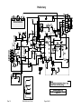
PGA309 Sensor Interface Board Schematic
8
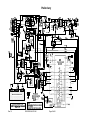
PGA309 PC Interface Board Schematic – Page 1 of 2
9
PGA309 PC Interface Board Schematic – Page 2 of 2
10
6.0 Initial Setup and Checkout
11-21
7.0 Board Control Software Overview
22-31
8.0 PGA309 + Sensor Calibration Spreadsheet for Microsoft® Excel
32-40
9.0 General Operating Tips
41
10.0 PGA309DK PC Cable Drawing
42
11.0 PGA309DK External EEPROM Settings for Functional Test
43
Note:
PGA309 Documentation Availability
Please read and familiarize yourself with the PGA309 Data Sheet and PGA309 User’s Guide prior to
using the PGA309DK Designer’s Kit since the PGA309 features and modes are not described herein.
Refer to Texas Instruments’ Website for latest revision of:
PGA309 Data Sheet and PGA309 User's Guide
http://focus.ti.com/docs/prod/folders/print/pga309.html
PGA309DK User's Guide and PGA309DK Software
http://focus.ti.com/docs/toolsw/folders/print/pga309dk.html
Rev 1.5
2/26/2004 8:46:00 AM
Page 2 of 45
Preliminary
1.0 PGA309DK Parts List
PGA309 PC Interface Board
PGA309 Sensor Interface Board
PC Cable (8-position RJ45 Plug to 9-position female DB9)
AC Wall Adapter (120Vac RMS, 60Hz in; 6Vdc, 200mA out) – USA Shipments Only
PGA309DK Software CDROM (Rev 1.0.7 or newer)
PGA309 Designer’s Kit Board Control Software
PGA309 Calibration Spreadsheet for Microsoft® Excel
PGA309DK User’s Manual
1.1 PGA309 Designer’s Kit Board Control Software - Operating System Compatibility
The Board Control Software runs on Win98, Win2000 and WinXP. Consult factory for other operating
systems.
1.2 PGA309 Calibration Spreadsheet for Microsoft® Excel - Operating System Compatibility
The Calibration Spreadsheet runs on Microsoft® Excel versions 2000, XP, 2003. Consult factory for other
versions.
2.0 Description
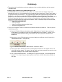
The PGA309DK key hardware consists of two boards (see Figure 1), PGA309 Sensor Interface Board and
PGA309 PC Interface Board. The PGA309 Sensor Interface Board contains the PGA309, external SOT23-5
EEPROM, and several jumpers for ease of bridge sensor configuration. The PGA309 PC Interface Board
contains an RS-232 serial interface, a 3V/5V programmable linear regulator, a switch for power control to the
PGA309 Sensor Interface Board, both One-Wire and Two-Wire interface configuration and control logic, and
an A/D Converter (ADS1100).
The PGA309DK is designed to allow the user to attach his sensor to the PGA309 Sensor Interface Board and
place this combination in a temperature chamber. By controlling the applied pressure to the pressure sensor
and the temperature of the temperature chamber, the PGA309 + Sensor combination can be calibrated for
optimum end module accuracy. The PGA309 Sensor Interface Board is rated for operation from -40°C to
+125°C. Power, ground, output and digital interface wires connect the PGA309 Sensor Interface Board in the
temperature chamber to the external PGA309 PC Interface Board. The PGA309 PC Interface Board
communicates to a test computer through a standard RS-232 serial port via the PGA309DK PC Cable. For
USA shipments an AC wall adapter is included to provide 6Vdc to the PGA309 PC Interface Board. For all
other applications an alternate connection on the PGA309 PC Interface Board is provided for connection to a
6Vdc (6Vdc-9Vdc) lab supply. The on-board A/D Converter, ADS1100, on the PGA309 PC Interface Board
allows for easy reading of the analog output of the PGA309.
The PGA309DK Software is comprised of two parts. The Board Control Software contains all of the interface
and control for communication to the PGA309 through the PGA309 PC Interface Board. It allows for reading
and writing to all registers in the PGA309 as well as reading and writing to the external SOT23-5 EEPROM.
Both Two-Wire and One-Wire communication options are available. In addition configuration of the PGA309
PC Interface Board and readback of the ADS1100 is provided. The PGA309 Calibration Spreadsheet for
Microsoft® Excel provides a useful tool to calculate optimum temperature coefficients for the PGA309 +
Sensor calibration based on real-world measurements of pressures at different temperatures. The PGA309
Calibration Spreadsheet also contains Visual Basic for Applications code that allows its integration with the
Board Control Software. These macros allow the user to exchange PGA309 settings between the program
and the spreadsheet and save the resulting EEPROM configuration file.
Rev 1.5
2/26/2004 8:46:00 AM
Page 3 of 45
Preliminary
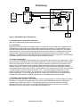
Figure 1: PGA309DK Typical System Setup
3.0 PGA309 Sensor Interface Board Overview
(Refer to PGA309 Sensor Interface Board Schematic)
3.1 Input/Output
Bridge sensor input connections are made though Tin, an 8-position screw terminal strip. In parallel with Tin
are plated-through holes that are provided for solder connections if so desired. The connections from the
PGA309 Sensor Interface Board to the PGA309 PC Interface Board are provided through Tio, an 8-position
screw terminal strip. This connector provides ease of connections to wires for the required selected signals
when placing the PGA309 Sensor Interface Board inside a temperature chamber for PGA309 + Sensor
calibration. In parallel with Tio is Jtest which provides a means for direct plug-in connection to the PGA309 PC
Interface Board. This is useful for initial checkout of the PGA309DK system.
3.2 Jumper Configuration
J1, J2, J3, J4, J5, J10 and J11 allow flexibility in the configuration of the connection to a bridge sensor. These
jumpers also allow connection of the on-board test resistor RTEST used for testing functionality of the PGA309
without any bridge sensor connected. Rt+ and Rt- allow for resistors to be used in the top or bottom of the
bridge sensor’s excitation path for one method of measuring bridge temperature by total bridge resistance
changes. Jumper J6 is used to configure the PGA309 circuit for external or internal temperature sensing. If
external temperature sensing using an RTD or external diode is to be used then set J6 to EXT and remove the
J1 jumper entirely to avoid any interaction with Rt+ or Rt-. J9 provides hardware configuration for either
internal or external reference voltage. J8 is used when Vout is to be tied to PRG for a 3-terminal sensor
module configuration. J12 and J7 together decide if the Test pin on the PGA309 is to be controlled by the
PGA309 PC Interface Board or hardware-programmed on the PGA309 Sensor Interface Board.
3.3 PGA309 + External SOT23-5 EEPROM
U1 is the PGA309 for evaluation. Also on-board is a 16k-bit, external, SOT23-5, industry standard Two-Wire,
EEPROM, U2. Although the PGA309 needs only 1k-bit of external EEPROM to access its configuration
registers plus the maximum number of 17 temperature coefficients, both the One-Wire and Two-Wire
interfaces allow access to locations in much larger EEPROMs which can be used to store user-specific
information such as a serial number, lot and date code information, etc.
Rev 1.5
2/26/2004 8:46:00 AM
Page 4 of 45
Preliminary
3.4 Protection and Filtering
The PGA309 Sensor Interface Board is configured with components to prevent mis-wire mishaps. If power is
provided from the PGA309 PC Interface Board, D1, is adequate to protect from overvoltages and reverse
polarity connections. CL is a standard EMI/RFI capacitor design with Riso and Rp providing up to 16V
overvoltage on VoutF. Input common mode plus differential noise filtering is provided by C3, C4, C5 and R3,
R4.
3.5 Test Points and Miscellaneous Breadboard Area
There are several Test Points, including a 3-position one for GND, provided for ease of measuring analog
signals. Also provided are reserved areas with plated-through, standard-spacing, 0.1” holes for miscellaneous
proof-of-concept breadboarding as desired for a given application.
4.0 PGA309 PC Interface Board Overview – Part 1
(Refer to PGA309 PC Interface Board Schematic, Sheet 1 of 2)
4.1 Input/Output
The connections from the PGA309 PC Interface Board to the PGA309 Sensor Interface Board are provided
through Tio, an 8-position screw terminal strip. This connector provides ease of connections to wires for the
required selected signals when placing the PGA309 Sensor Interface Board inside a temperature chamber for
PGA309 + Sensor calibration. In parallel with Tio is Ptest which provides a means for direct plug-in connection
to the PGA309 Sensor Interface Board. This is useful for initial checkout of the PGA309DK system. Ppc is an
8-position RJ45 jack for connection through the PGA309DK PC cable to a test computer’s RS-232 serial port.
RS-232 compatible signals are generated through U9. Power for the PGA309 PC Interface Board is provided
through either Jpwr or Tpwr. Jpwr is to be used when an AC Wall Adapter (120Vac RMS, 60Hz in; 6Vdc,
200mA out) is available – USA Shipments Only. Other applications will use a 6Vdc (6Vdc-9Vdc) lab supply
and the screw terminal inputs on Tpwr. U7 provides a regulated power source of either 3V or 5V, selectable
through JA. D3 provides protection from inadvertent reverse polarity connections on Jpwr or Tpwr.
4.2 Port Expander Configuration Control
U5 is an 8-bit serial port expander PCF8574A which allows user control over the configuration of the PGA309
PC Interface Board. D1 and D2 are controlled by the Board Control Software and are used as diagnostic
LEDs. Q1, also controlled through U5, provides a mechanism to turn power on and off to the PGA309 Sensor
Interface Board by the Board Control Software. This is key when PRG is connected to Vout on the PGA309
since Vout is set to high impedance on power-up for 25ms to allow for One-Wire communication. An unused
port, P3, pin 7 is available for customer use with control provided in the Board Control Software. The OneWire pull-up resistor, R3 can be disabled through U5 to remove loading from the PGA309 Vout pin for an
accurate readout through the ADS1100, U3. U5 also controls the zero calibration of the ADS1100. The TwoWire interface can be isolated from the PGA309 Sensor Interface Board by software through U5 control of U10
and U11 or also by hardware jumper programming.
4.3 One-Wire Digital Interface
On this Designer’s Kit the One-Wire digital interface is the preferred mode of communication with PGA309. It
is provided through the conversion of RS-232 UART signals from U9 into open drain output through U2. The
resistive pull-up for the One-Wire interface is enabled or disabled through U1. The One-Wire pull-up can be
disabled for an accurate PGA309 Vout reading without the extra loading due to R3. JC provides a selection
for the One-Wire active pull-up (1PU) or no One-Wire active pull-up (1NPU). This feature is described in detail
in Section 5.1. Jumper JB provides a mechanism for communication through Vout when PRG is tied to Vout
on the PGA309 for a 3-terminal sensor module configuration.
Rev 1.5
2/26/2004 8:46:00 AM
Page 5 of 45
Preliminary
4.4 Two-Wire Digital Interface
Two-Wire digital interface is provided through the conversion of RS-232 signals from U9 into open drain
outputs with pull-ups (SDAOUT through U6 and SCLOUT through U8). SDAIN is tied direct to U9 which is looking
for <0.8V for a logic low and >2.0V (3V supply) or >2.4V (5V supply) for a logic high. U10 and U11 provide a
mechanism, through software or hardware (JE), to separate the Two-Wire bus interface from the PGA309 if it
is physically connected. If the PGA309 is in stand-alone mode it will be routinely accessing its external
EEPROM via the Two-Wire interface as a master. By disconnecting from the PGA309 Two-Wire connections
dedicated, local Two-Wire transactions on the PGA309 PC Interface Board such as reading the ADS1100, U3,
can be conducted reliably and without interruption.
Note: It is recommended to keep One-Wire interface on the PGA309 PC Interface Board connected to
the PGA309 Sensor Interface Board even when using Two-Wire communication mode to the PGA309
and EEPROM from the PGA309DK Board Software. See Section 7.8 for details.
4.5 ADS1100 (On-Board A/D Converter)
The ADS1100 is a 16-Bit A/D available to measure Vout from the PGA309. The ADS1100 is configurable
through the Board Control Software. U4 provides a means of measuring the ADS1100 initial offset for
improved accuracy in its readings.
4.6 Test Points and Miscellaneous Breadboard Area
There are several Test Points, including a 3-position one for GND, provided for ease of measuring analog
signals. Also provided are reserved areas with plated-through, standard-spacing, 0.1” holes for miscellaneous
proof-of-concept breadboarding as desired for a given application.
5.0 PGA309 PC Interface Board Overview – Part 2
(Refer to PGA309DK PC Interface Board Schematic, Sheet 2 of 2)
5.1 One-Wire Active Pull-Up
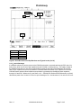
The One-Wire Active Pull-Up circuitry is intended to provide a fast rising edge pull-up when the One-Wire
interface is connected to heavy capacitive loads such as when PRG is tied to Vout on the PGA309 and there
is a 10nF capacitor on Vout to GND. In this configuration there is an extremely long rise time due to a 4.7kΩ
pull-up on the One-Wire interface. One-Shot U14 is rising edge triggered only, non-retriggerable. Comparator
U12 looks for a rising edge to transition above 0.7V. The One-Shot, U14, then triggers and produces a 5μS
wide pulse which controls switch U13. When switch U13 is turned on a 200Ω pull-up to VS is provided on the
One-Wire Interface. At the end of the 5μS pulse the 200Ω pull-up to VS is removed. The 5μS was chosen to
provide a near-symmetrical rise and fall time into a 10nF load on the One-Wire interface. RT is a provisional
potentiometer which can be added to change the time the active pull-up is applied to the One-Wire Interface.
D5, D6 and R22 proved a clamp to keep the input of U12 inside its allowed input voltage range for reliable
operation. Figure 2 illustrates the One-Wire Pull-Up into a non-capacitive load. The table shows typical
values for a supply voltage of 3.0V.
Rev 1.5
2/26/2004 8:46:00 AM
Page 6 of 45
Preliminary
Parameter
VPU
VHI
VLO
tPU
Typical
3.0V
2.63V
122mV
5μs
Figure 2: One-Wire Active Pull-Up Waveform and Typical Levels (VS=3V)
5.2 VS Quick Discharge
It is desired at times to cycle the power on the PGA309 to be able to communicate through PRG, when it is
tied to Vout, while Vout is set to high impedance by the PGA309 on initial power-up. The supply voltage on
the PGA309 must decay to near zero to ensure that on power-up the state of the PGA309 is set correctly.
With a 10μF capacitor on Vs on the PGA309 PC Interface Board and another 10μF capacitor on Vs on the
PGA309 Sensor Interface Board reliable reset operation is guaranteed by discharging these capacitors
through U15 and R25. Whenever Q1 (see Sheet 1 of 2 – PGA309 PC Interface Board Schematic) is off and
disconnects power from Vs then U15 is on for quick discharge of Vs. And whenever Q1 is on then U15 is off.
Rev 1.5
2/26/2004 8:46:00 AM
Page 7 of 45
Preliminary
24LC16BE
SOT-23
-40C to +125C
+
Rev 1.5
2/26/2004 8:46:00 AM
Page 8 of 45
C14
1WPU
SN74LVC1G07
SN74LVC1G66
Rev 1.5
2/26/2004 8:46:00 AM
Page 9 of 45
0.01 F
SN74LVC1G66
Preliminary
Preliminary
Rev 1.5
2/26/2004 8:46:00 AM
Page 10 of 45
Preliminary
6.0 Initial Setup and Checkout
6.1 PGA309 Sensor Interface Board – Factory Jumper Settings
Confirm and/or set the jumpers on the PGA309 Sensor Interface Board as shown in Figure 3. The desired
jumper settings are also described in Table 1.
Figure 3: PGA309 Sensor Interface Board – Factory Jumper Settings
PGA309 Sensor Interface Board – Factory Jumper Settings
Jumper
Position
J1
RtUse on-board pot for bridge
J2
TEST
Use on-board pot for bridge
J3
TEST
Use on-board pot for bridge
J4
VEXC
Use PGA309 Vexc
J5
TEST
Use on-board pot for bridge
J6
INT
Use on-chip temp sensor
J7
RUN
Use EEPROM for settings
J8
PRG
PRG not connected to VOUT
J9
INT
Internal Reference
J10
SHORT
Use on-board pot for bridge
J11
SHORT
Use on-board pot for bridge
J12
PC
PC Interface Board control for Test Mode
Rev 1.5
2/26/2004 8:46:00 AM
Page 11 of 45
Preliminary
Table 1: PGA309 Sensor Interface Board – Factory Jumper Settings
6.2 PGA309 PC Interface Board – Factory Jumper Settings
Confirm and/or set the jumpers on the PGA309 PC Interface Board as shown in Figure 4. The desired jumper
settings are also described in Table 2.
Figure 4: PGA309 PC Interface Board – Factory Jumper Settings
PGA309 PC Interface Board – Factory Jumper Settings
Jumper
Position
JA
5V
PGA309 operates at +5V
JB
PRG
PRG not connected to VOUT
Dynamic One-Wire Pullup
JC
1PU
Enabled
PC Serial Interface loopback set
JD
RTS
for CTS-RTS
JE
PC
Two-Wire Enable Control by PC
JF*
SDN
RS-232 Auto Shutdown Mode
*Rev A Boards Only
Table 2: PGA309 PC Interface Board – Factory Jumper Settings
Rev 1.5
2/26/2004 8:46:00 AM
Page 12 of 45
Preliminary
6.3 Hardware Setup (see Figure 5)
Plug the PGA309 Sensor Interface Board into the PGA309 PC Interface Board. On the PGA309 PC Interface
Board connect a 6Vdc (6Vdc-9Vdc) Lab Supply into Tpwr or an AC Wall Adapter (120Vac RMS, 60Hz in;
6Vdc, 200mA out - USA Shipments Only) into Jpwr. Connect the PGA309DK PC Cable from Ppc (RJ-45 jack)
on the PGA309 PC Interface Board to an RS-232 serial port on the Test Computer.
Figure 5: Hardware Setup – Initial Checkout
6.4 Board Control Software Installation
1) The PGA309Dk Board Control Software is installed in the normal Microsoft® Windows manner. Close all
other applications. From “Start” button on the task-bar select “Run”.
2) In the Run Window type:
d:\setup
where “d” is the letter designation of the CD-ROM drive containing the PGA309DK Software CD-ROM.
3) Follow the on-screen prompts to install the software.
4) To remove the PGA309DK application use the Windows Control Panel utility “Add/Remove Software”.
6.5 Software/Hardware Initial Checkout
At this point no LEDs should be lit on the PGA309 PC Interface Board. If any LEDs are lit cycle the power on
the PGA309 PC Interface Board.
Rev 1.5
2/26/2004 8:46:00 AM
Page 13 of 45
Preliminary
6.5.1 Software Startup
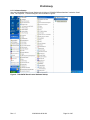
Start the PGA309DK Board Control Software by clicking on “PGA309 DK Board Interface” under the “Start”
menu, “All Programs”, “PGA309 Designer’s Kit” as shown in Figure 6.
Figure 6: PGA309DK Board Control Software Startup
Rev 1.5
2/26/2004 8:46:00 AM
Page 14 of 45
Preliminary
6.5.2 Software Board Communication Setup – Default
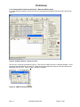
On initial software startup a Main Window will appear with a smaller pop-up window in the middle of the Main
Window. Click “Yes” on the pop-up window (see Figure 7). If the initial software startup does not look like
Figure 7 then proceed directly to Section 6.5.3.
Figure 7: Software Startup – Main Window and First Pop-up Window
Rev 1.5
2/26/2004 8:46:00 AM
Page 15 of 45
Preliminary
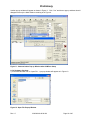
The First Pop-Up Window will disappear and the Main Window should look as in Figure 8. If it does then
proceed to Section 6.5.4 and skip Section 6.5.3.
Figure 8: Software Startup – Main Window
Rev 1.5
2/26/2004 8:46:00 AM
Page 16 of 45
Preliminary
6.5.3 Software Board Communication Setup – Manual COM Port Setup
If on initial software startup the right Com port is not selected automatically then the first screen will look like
Figure 9.
Figure 9: Software Startup – Wrong Com Port
Click on “OK” in the pop-up window in Figure 9. Then click on “COM Port Setup” in the Main Window. A new
pop-up window will appear as in Figure 10. Select the serial port where the board is connected and desired
Baud Rate and click “OK”. Ensure “1Wire” Interface is selected.
Figure 10: COM Port Pop-up Window
Rev 1.5
2/26/2004 8:46:00 AM
Page 17 of 45
Preliminary
Another pop-up window will appear as shown in Figure 11. Click “Yes” and the two pop-up windows should
disappear with only the Main Window remaining as in Figure 8.
Figure 11: Communication Pop-up Window after COM Port Setup
6.5.4 Hardware Checkout
1) In the Main Window click on “Open File”. A pop-up window will appear as in Figure 12.
Figure 12: Open File Pop-up Window
Rev 1.5
2/26/2004 8:46:00 AM
Page 18 of 45
Preliminary
2) Select “PGA309DK Test.txt” and open this file (on the PGA309DK CDROM). A pop-up window will appear
as in Figure 13. Click on “OK”.
Figure 13: Open File Acknowledge Pop-up Window
The Main window will appear as in Figure 14.
Figure 14: Main Window After Open File = “PGA309 Test.txt”
Rev 1.5
2/26/2004 8:46:00 AM
Page 19 of 45
Preliminary
Table 3 defines the PGA309 settings defined by this file (PGA309 Test.txt).
Vref
Vexc
Coarse Offset
Vdiff
Vout
PGA Gain
Fine Gain
Out Amp Gain
Zero DAC
4.096
3.4V
-3.277mV
(0V-3.277mV) = -3.277mV
-0.263V (ideal)
X64
X1
X2.4
100mV
Internal
X0.83(Vref), Enabled
Over-Scale
Under-Scale
3.976V (ideal)
0.248V (ideal)
000 (0.9708 Vref)
111 (0.06054 Vref)
Fault Detect
EXTEN=1
INTEN=0
OUEN=1
Enable External Fault Comparator Group
Disable Internal Fault Comparator Group
Enable Over/Under-Scale Limits
(33.67mV-3.277mV) = 30.393mV
4.908V (ideal)
Table 3: PGA309DK Sensor Interface Board Functional Test Settings
3) Write these settings to the PGA309 Sensor Interface Board EEPROM by clicking on “Write EEPROM” in the
Main Window. Click on “Read EEPROM” and then click on “Read PGA309”. The Main Window should look
the same as in Figure 14 .
4) Configure ADS1100 for continuous readback. In the Main Window click on “Board Settings”. The Status
Window (“ADS1100 and PCF8574A Status” Window) will appear as in Figure 15.
Figure 15: Status Window
Rev 1.5
2/26/2004 8:46:00 AM
Page 20 of 45
Preliminary
5) In the Status Window check the box to “Read ADS1100 Continuously”.
6) In the Main Window set “Supply Vcc (V)” to 5.0V
7) The “Rtest” potentiometer and “J4” on the PGA309 Sensor Interface Board will be used for this test. On the
PGA309 PC Interface Board the ADS1100 ADC will be used for this test. Table 4 below details the
actions and acceptable results for a pass condition of the PGA309 Sensor Interface and PGA309 PC
Interface Boards.
Step
Rtest
1
Rotate Fully Clockwise
(until audible clicking is heard)
Rotate Fully
Counter-Clockwise
(until audible clicking is heard)
Don’t Care
Replace J4
2
3
4
J4
Position
Vexc
ADS1100 read
(Volts min)
0.19
ADS1100 read
(Volts max)
0.26
Vexc
3.9
4.1
Open
Vexc
4.9
Don’t Care
5.0
Don’t Care
Table 4: Hardware Checkout Voltages and Settings
8) In the Main Window, under “PGA309 Temp ADC”, click on “Convert” (see Figure 16).
9) Temperature reading in °C should be the PGA309 ambient +/-2°C. Readout will be in Main Window under
“PGA309 Temp ADC” section as shown in Figure 16.
Figure 16: Internal Temperature Reading
If all steps above, in Section 6, have been successfully completed then the PGA309 Sensor Interface Board,
PGA309 PC Interface Board, PC Cable, PGA309DK Board Control Software are all operating correctly.
Rev 1.5
2/26/2004 8:46:00 AM
Page 21 of 45
Preliminary
7.0 Board Control Software Overview
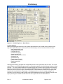
Figure 17 depicts the Main Window for the Board Control Software. Subsections of the Main Window (outlined
by dashed lines) as well as the “Top Row Control Buttons” and “Board Communication Status” will be
described in detail in sections 7.1-7.10.
Top Row
Control Buttons
Board Communication Status
Figure 17: Main Window
Rev 1.5
2/26/2004 8:46:00 AM
Page 22 of 45
Preliminary
7.1 Top Row Control Buttons
The “Top Row Control Buttons” are described in Table 5.
Button Name
Description
Comments
Reset
Resets all register bit values to zero
Resets values in PC memory
only. Requires a “Write to
PGA” or “Write to EEPROM”
to effect
Open File
Selects File to open which contains
saved EEPROM Configuration Register
and Lookup Table values.
Selects File to save current EEPROM
Configuration Register and Lookup Table
values.
Looks for PGA309DK Boards using
current “Port Setup”. Configures the
board and read the current Register and
the Lookup Table values
Writes all current Main Window values
into PGA309 R/W Registers (including
setting ZeroDAC and GainDAC).
Save File
Detect
Write PGA309
Read PGA309
Write EEPROM
Read EEPROM
See Related
Figure ?
Figure 18
Figure 18
Both PGA309 Sensor
Interface and PGA309 PC
Interface must be present and
working.
Unless Test Pin is set high
these settings will be
overwritten by valid external
EEPROM data.
Reads all current PGA309 Register
values into the Main Window.
Writes current values in the Lookup
Table section and PGA309 Register
section of the Main Window into external
PGA309 EEPROM.
Reads external PGA309 EEPROM
values into Main Window.
Table 5: Main Window - Top Row Control Buttons
7.1.1 General Note on Reading & Writing to PGA309 and External EEPROM:
When you do a “Write EEPROM” whatever is in the “Main Window” will be written to the PGA309 external
EEPROM EXCEPT for the Zero DAC and Gain DAC values in the “PGA Settings” section of the “Main
Window”. However, in the case of the Zero DAC and the Gain DAC it does not make any sense to write to the
EEPROM the settings in the section “PGA Settings” since the Zero DAC and Gain DAC settings can be many
values as defined by the Lookup section of the EEPROM. To write Zero DAC and Gain DAC settings into
EEPROM you must update or change the “Lookup Table” section in the “Main Window”. Also if you
type a number into the Zero DAC or Gain DAC boxes in the “PGA Settings” section of the “Main
Window” and then do a “EEPROM Read” the previously typed numbers will remain. To read the
current Gain DAC and Zero DAC settings of the PGA309 internal registers and have them updated and
displayed in the “PGA Settings” section of the Main Window click on the “Read PGA309” Button.
If you want to try different settings on the PGA309 then it is best to check the box “PGA309 Test Pin High” in
the upper middle area of the “Main Window” which stops the PGA309 from reading the EEPROM and allows
you to “Write PGA309” which will directly change (but NOT save to EEPROM) the Zero DAC and Gain DAC
settings for trial offset and gain settings, etc.
Rev 1.5
2/26/2004 8:46:00 AM
Page 23 of 45
Preliminary
Figure 18: Typical Write PGA309 or Read PGA309 Pop-up Window
7.2 EEPROM Lookup Table
When the “EEPROM Lookup Table” is selected on the bottom Tab in the Main Window the Temperature
Coefficients stored in the PGA309 external EEPROM from the last “Read EEPROM” are displayed in the
“Lookup Table” section of the Main Window. These values can be displayed by selecting the desired format
as Binary, Hex or Decimal under “Display Mode” in the “Lookup Table” section. See Figure 17. If the entire
contents of the EEPROM is to be viewed or edited, in Hex and ASCII only, then click on “Show 1kBit
EEPROM” in the “Lookup Table” section of the Main Window. Figure 16 shows the resultant pop-up window
which displays the entire external PGA309 EEPROM contents in Hex. Remember the EEPROM contents are
mapped least significant byte first relative to PGA309 16-Bit registers as shown in Figure 20.
Figure 19: PGA309 External EEPROM Pop-up Window
Rev 1.5
2/26/2004 8:46:00 AM
Page 24 of 45
Preliminary
PGA309 Internal Registers
D15
D14
D13
D12
D11
D10
D9 D8
D7 D6 D5 D4 D3 D2 D1 D0
External EEPROM
D7
D6
D5
D4
D3
D2
EEPROM Location
D1 D0
0x00
D15 D14 D13 D12 D11 D10 D9 D8
0x01
Figure 20: PGA309 Internal Registers to PGA309 External EEPROM Mapping
For updating the information in the “EEPROM Lookup Table” section simple click and edit the desired values.
Next click on the “Apply Changes” button in the “EEPROM Lookup Table” section. This only updates the
information for the Lookup Table information stored on the Test PC. If these new values are desired to be
written into the external EEPROM, then after the “Apply Changes” click one must click on the “Write EEPROM”
button at the top of the Main Window. If the changes edited in the Lookup Table are desired not to be kept on
the Test PC then click on “Discard Changes” and the last values in the Lookup Table stored on the Test PC
will be restored.
The other way to directly write to the external EEPROM is through the “PGA309 External EEPROM Pop-up
Window” as shown in Figure 19 and discussed above.
7.3 PGA309 Registers
The PGA309 current internal register contents are displayed in the “PGA309 Registers” section of the Main
Window. By clicking on the “Bitmap of a register” tab in the bottom left corner of the Main Window the Main
Window view will change to that of Figure 21. The lower left quadrant of the Main Window now displays
detailed information about the PGA309 register selected by clicking on a specific register listed in the “PGA309
Registers” section of the Main Window. Each bit in the selected register may be toggled by double-clicking on
the desired current bit setting. A brief description of each bit also appears. If the “Instant Update” check-box
in the lower right of the Main Window is not checked than the “Write PGA309” button will need to be pushed.
Remember if you do not want the register settings in the PGA309 to be over-written by valid PGA309 external
EEPROM data then ensure the PGA309 Test pin is set high by checking the “PGA309 Test Pin HIGH” box in
the upper left area of the Main Window.
Rev 1.5
2/26/2004 8:46:00 AM
Page 25 of 45
Preliminary
Figure 21: PGA309 Registers – Main Window
7.4 PGA Settings
Rather than toggling individual bits of the registers described above, the PGA309 can be configured using
drop-down menu selections or check-boxes in the “PGA Settings” section of the Main Window contains:
Input Referred Offset (mV)
Frontend PGA Gain (V/V)
Fine Zero DAC (V)
Fine Gain DAC (V/V)
Output Amplifier (V/V)
Enable Over/Under-Scale Limits
Overscale Limit
Underscale Limit
Enable Sensor Excitation
Linearization Coef (V/V)
Enable Internal Vref
Vref Value
Changing these settings will update the corresponding bits of in the register table and vice versa. The current
values of these and the PGA309 registers will be automatically updated in the Main Window following a “Read
PGA309”. The current settings displayed in the Main Window will be written to the PGA309 internal registers
following a “Write PGA309” or to the external PGA309 EEPROM following a “Write EEPROM”. If the “Instant
Update” check-box in the lower right of the Main Window is checked then the PGA309 internal registers will
automatically be updated after every change. Remember if you do not want the register settings in the
PGA309 to be over-written by valid PGA309 external EEPROM data then ensure the PGA309 Test pin is set
high by checking the “PGA309 Test Pin HIGH” box in the upper left area of the Main Window.
Rev 1.5
2/26/2004 8:46:00 AM
Page 26 of 45
Preliminary
7.5 Fault Detection
In the “Fault Detection” section of the Main Window the following check-boxes are provided for fault detection
configuration:
Detect External Faults (checked means enable detection of external faults)
Detect Internal Faults (checked means enable detection o internal faults)
Vout high on external fault (unchecked means Vout low on external fault)
Vout high on internal fault (unchecked means Vout low on internal fault)
The current settings of these in the PGA309 registers will be automatically updated in the Main Window
following a “Read PGA309”. The current settings displayed in the Main Window will be written to the PGA309
internal registers following a “Write PGA309” or to the external PGA309 EEPROM following a “Write
EEPROM”. If the “Instant Update” check-box in the lower right of the Main Window is checked then the
PGA309 internal registers will automatically be updated. Remember if you do not want the register settings in
the PGA309 to be over-written by valid PGA309 external EEPROM data then ensure the PGA309 Test pin is
set high by checking the “PGA309 Test Pin HIGH” box in the upper left area of the Main Window.
7.6 PGA309 Temp ADC
In the “PGA309 Temp ADC” section of the Main Window the current Temp ADC reading will be displayed if the
“Convert” button is pushed. If a continuous update of the Temp ADC contents is desired it can be read and
updated about every 0.75 second by checking the box labeled “Keep Comm Alive” in the lower right corner of
the Main Window. Please note that this will also prevent the 1s timeout in the PGA309 from expiring thus
stopping EEPROM read-back updates even if Test Pin is low.
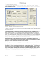
By clicking on the “ADC Config” button a pop-up window will be displayed as shown in Figure 22. The flexible
Temp ADC can be configured as desired for the application. For details of the Temp ADC options and settings
see the PGA309 Data Sheet. If the settings are changed and to be applied then click “OK” in the pop-up
window. Remember if you do not want the register settings in the PGA309 to be over-written by valid
PGA309 external EEPROM data then ensure the PGA309 Test pin is set high by checking the “PGA309 Test
Pin HIGH” box in the upper left area of the Main Window. If these changes are to be included in the EEPROM
then set the Test pin HIGH while configuring the Temp ADC, then “Write EEPROM” then set Test pin low for
continuous EEPROM reads by the PGA309 with the new Temp ADC settings.
Figure 22: PGA309 Temp ADC Configuration & Readback
Rev 1.5
2/26/2004 8:46:00 AM
Page 27 of 45
Preliminary
7.7 Interface Board and ADS1100
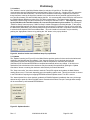
In the “Interface Board and ADS1100” section, in the Main Window, click on “Board Settings”. A pop-up
window will appear as in Figure 23. This pop-up window provides configuration control of the ADS1100 and
the Port Expander, PCF8574A.
Figure 23: “ADS1100 and PCF8574A Status” Window
In the pop-up window the bits under “EVM (PCF8574A)” will toggle when single-clicked. Table 6 describes the
use of each of these bits.
If the “Calibrate ADS1100” Button is pushed it will short the two inputs of the ADS1100 together and compute
the offset error. All ADS1100 readings which follow will be calibrated to account for this offset error. In
addition measure the voltage Vs on the PGA309 PC Interface Board with an accurate meter and enter this
voltage in the “Supply Vcc (V)” box in the Main Window or enter this voltage into the “Vs=” box in the pop-up
window. After these two ADS1100 calibration steps are complete the ADS1100 is fully calibrated for both gain
and offset errors. Each time the “Calibrate ADS1100” Button is pushed a new ADS1100 offset calibration is
performed and the subsequent readings will use the latest calibration numbers.
If the “Read ADS1100” button is pushed a single conversion will be performed in the ADS1100. The reading
will be updated in both the Main Window and in the pop-up window. If the box labeled “Read ADS1100
Continuously” is checked then both the pop-up window and Main Window ADS1100 readings will be updated
about every 2 seconds depending upon the operating system conditions.
The “ADS Output Register” section in the pop-up window is a read-only bit readout of the latest ADS1110
conversion.
The “ADS1100 Configuration Status Register” bits allow for custom configuration of the ADS1100. These bits
are toggled by a one-click method in the corresponding box. The default setting is 0x8C. This configures the
ADS1100 for Continuous Conversion Mode, Internal PGA=x1, and 8 samples per second data rate. If these
settings are changed they can be returned to the initial power-up settings by pushing the “Gen Call Reset” in
the pop-up window. If the Vcc voltage on the PGA309 PC Interface Board is changed then the ADS1100 will
need to be re-calibrated for gain and offset (this assumes Vcc will become the Vs for the PGA309 Sensor
Interface Board). For further ADS1100 details consult the ADS1100 data sheet.
Rev 1.5
2/26/2004 8:46:00 AM
Page 28 of 45
Preliminary
P7
Test pin
P6
nLED2
P5
nLED1
Logic
State
0
PGA309 operates in “Normal / StandAlone Mode”.
Reads external EEPROM and uses
temperature coefficients to update Gain DAC
and Zero DAC settings.
No external EEPROM reads and must be
manually written to for changes in DACs or
register settings.
LED D2 is turned on by the Board Control
Software if “PGA309 Test Pin HIGH” box in
the Main Window is checked.
LED D2 is turned off by the Board Control
Software if “PGA309 Test Pin HIGH” box in
the Main Window is not checked.
LED D1 is turned on by the Board Control
Software when successful communication has
been completed after power-on from zero
volts on the PC Interface Board.
PGA309 operates in “Test Mode”.
0
Turns on LED D2 on PGA309 PC
Interface Board.
1
Turns off LED D2 on PGA309 PC
Interface Board.
0
Turns on LED D1 on PGA309 PC
Interface Board.
1
Turns off LED D1 on PGA309 PC
Interface Board.
Normal ADS1100 input operation.
Shorts ADS1100 inputs (VIN+ and VIN-)
together for offset calibration.
Logic output of port expander port P3,
PGA309 PC Interface Board, U5,
pin 7.
Disables the Two-Wire interface from
the PGA309 Sensor Interface Board.
0
1
P2
2WEN
0
0
1
1
P0
1Wen
Comments
1
P4
ADS1100
Cal
P3
P1
nVSen
Description
0
Enables the Two-Wire interface from
the PGA309 Sensor Interface Board.
Applies Vs to PGA309 Sensor
Interface Board.
1
Removes Vs from PGA309 Sensor
Interface Board.
0
Disable 4.7kΩ One-Wire pull-up
resistor.
Enable 4.7kΩ One-Wire pull-up
resistor.
1
Used in the ADS1100 calibration sequence by
the Board Control Program
Spare port expander port available for user
application if desired.
To allow reliable, uninterrupted connection to
ADS1100 and PCF8574A when PGA309 is in
Stand-Alone Mode set this bit to zero.
To allow for Two-Wire digital communication
from PC to PGA309 and external EEPROM.
Important when PRG is connected to Vout on
PGA309 to ensure One-Wire communication
during power-up.
Important when PRG is connected to Vout on
PGA309 to ensure One-Wire communication
during power-up.
Important to disable for unloaded PGA309
Vout accurate reading through ADS1100.
Table 6: Functionality of Port Expander (PCF8574A) Bits
(default initial values selected by the Board Control Software are highlighted in bold)
Rev 1.5
2/26/2004 8:46:00 AM
Page 29 of 45
Preliminary
7.8 Interface
The “Interface” section in the Main Window allows for selection of One-Wire or Two-Wire digital
communication with the PGA309 Sensor Interface Board. Refer to Figure 24. A single click in the respective
circle will select the desired interface. All Board Control Software functionality is supported over either of
these interfaces, however the One-Wire interface is the preferred one due to potential conflicts arising from
two Two-Wire masters (PC and PGA309) sharing the bus. It is recommended to have PRG wire connected on
the PGA309 Sensor Board even when using Two Wire communication. The Board Control Software
addresses PGA309 using One-Wire interface prior to closing the switches U10/U11. This stops any activity
by the PGA309 on the Two-Wire interface for 1 second and prevents any bus conflicts. By pushing the
“COM Port Setup” button a pop-up “COM Port Setup” window will appear in the Main Window. In the pop-up
window the desired interface may also be selected as well as which PC COM port (“Port #”) will be used and
the Baud Rate (“Baud Rate”) for Communication through the selected COM Port. Drop-down menus are used
to select both the desired COM Port and Baud Rate. Once the interface is selected it may be tested by
pushing the “Apply/Detect” button or by pushing the “OK” button, in the pop-up window.
Figure 24: Interface Section and COM Port Setup Pop-up Window
7.9 Updates
The “Updates” section (see Figure 25) in the Main Window provides options for how certain calculations and
readings in the Main Window are updated. If the “Autocalc Chksum” box is checked then both the
configuration register part checksum (Checksum1) and the temperature coefficient part checksum
(Checksum2) for the external EEPROM are computed automatically after every change. If the box is not
checked then the calculations of the checksums may be manually accomplished by pushing the “Update
Checksums” button or entering the checksum values directly from hand calculation.
The “Keep comm alive” box, when checked, reads the Temp ADC register and updates the Main Window
reading about every 0.75 second, depending upon the operating system used. This will prevent the 1s timeout
in the PGA309 from expiring thus stopping EEPROM read-back updates even if Test Pin is set low.
The “Instant Update” box, when checked, updates the PGA309 Registers immediately after every bit change
without having to push the “Write PGA309” button. Remember that unless Test pin is set high these settings
will be overwritten by valid external EEPROM data.
Figure 25: Updates Section
Rev 1.5
2/26/2004 8:46:00 AM
Page 30 of 45
Preliminary
7.9 Board Communication Status
The “Board Communication Status” section (see Figure 26) is located in the bottom left corner of the Main
Window. When reads or write to the PGA309 internal registers or PGA309 external EEPROM are executed
messages will appear in this window as confirmation that the communication is taking place successfully.
Figure 26: “Board Communication Status” Section
7.10 Miscellaneous Main Window Boxes
In the upper left corner of the Main Window, under the “Top Row Control Buttons”, there are two check boxes
as shown in Figure 27.
“PGA309 Test Pin High” if checked will put a logic high on the Test pin. See Table 6 for the description of the
Test pin function. LED D2 on the PGA309 PC Interface Board will be lit whenever this box is checked (Logic
High).
If the PGA309 is to be configured with its PRG pin tied to Vout then the box labeled “PRG pin shorted to Vout”
(see Figure 27) must be checked for reliable operation. With this box checked the Board Control Software will
cycle power on the PGA309 each time it tries to communicate with PGA309 over One Wire interface to ensure
that Vout is in high impedance on the PGA309 during the first 25ms after power up.
Figure 27: Miscellaneous Main Window Boxes
Rev 1.5
2/26/2004 8:46:00 AM
Page 31 of 45
Preliminary
8.0 PGA309 + Sensor Calibration Spreadsheet for Microsoft® Excel
The PGA309DK includes a Microsoft® Excel spreadsheet that provides a way to perform a calibration of the
sensor module (PGA309 + sensor). The spreadsheet contains two parts:
Sensor Curve-Fitting Equations
Generation of Values for the PGA309 Temperature Lookup Table and Internal Register Settings.
The spreadsheet also contains VBA (Visual Basic for Applications) code that allows its integration with the
Board Control Software. These macros allow the user to exchange PGA309 settings between the program
and the spreadsheet and save the resulting EEPROM configuration file.
The flexibility and wide availability of Excel determined the platform for this solution. You are free to customize
the sensor curve-fit model to fit your sensor better. The only prerequisites are familiarity with Microsoft Excel®
capabilities and some limited knowledge of Visual Basic for Applications.
8.1 Sensor Curve-Fitting Equations
The built-in equations approximate the sensor with second order polynomials for each of the sensor three
variables:
- Span vs. temperature;
- Zero offset vs. temperature ;
- Output signal vs. sensor input variable: it will be simply called pressure from now on, but can also be
flow or another measured physical parameter.
The sensor curve-fit equation for this case is:
(Equation1)
(
)(
K bridge ( p, T ) = k0 + k1T + k 2T 2 + k3 p + k 4 p 2 ⋅ 1 + k5T + k6T 2
)
where:
Kbridge = bridge output function in V/V of excitation
p = sensor input variable (pressure, etc.)
T = temperature in degrees C
k0,k1,k2 = offset polynomial coefficients (initial, first and second order drift)
k3,k4 = input variable sensitivity and non-linearity
k5,k6 = span first and second order temperature drift
This is the sensor model used in the PGA309 Calibration Spreadsheet.
There are three degrees of freedom in this equation (offset and span vs. temperature and sensitivity vs.
pressure), each of them is described with a quadratic equation. If we don’t know much about the sensor
(besides that it can be approximated with the Equation1), we need to measure three points on each degree of
freedom for curve-fitting, i.e. 9 measurements: zero- and full-scale output at 3 temperatures each for offset and
span and output at 3 pressure level for sensitivity. Since the min and max pressure levels for the sensitivity
can be combined with zero and span measurements, this reduces the total number to 7 measurements: zero-,
half-, full-scale at one of the temperatures; zero- and full-scale at each of two other temperatures. This is
called the 3 temperature + 3 pressure calibration.
Since over-temperature calibration in an oven is often a lengthy and expensive process, it is often preferred to
characterize the span and offset drift non-linearities on some number of sensor samples and avoid using the
3rd temperature test in production. In this case, if we know that the sensor exhibits, for example 9% span drift
non-linearity over the full temperature range and we measure only two points on this curve, we can find the
equation coefficients. The same is true for offset drift and pressure non-linearity. By using this precharacterization method we can reduce the number of required measurements to 2 temperature points with 2
pressure levels at each (2 temperature + 2 pressure calibration)
In cases when the pressure non-linearity is not known due to bridge resistor value mismatch or other reasons,
three pressure levels need to be measured at one of these temperatures (2 temperature + 3 pressure
calibration).
The PGA309 Calibration Spreadsheet includes templates for each of the three methods described above. The
exact equations for curve-fitting the sensor are not included in this document, but can be extracted from the
spreadsheet cell formulas.
Rev 1.5
2/26/2004 8:46:00 AM
Page 32 of 45
Preliminary
8.2 Calibration of Signal Path Errors
Since we are interested in calibrating the output of a full module, “Sensor+PGA309”, we can measure the
output of the PGA309. Then we curve-fit the result to the same model. This will take into account all offsets,
gain errors and drifts of the amplification signal path.
PGA309 and sensor must be pre-configured with desired settings: reference, excitation level, coarse gain,
offset, A/D configuration, etc. The coarse settings should be based on preliminary characterization of the
sensor and be such that the PGA309 produces a reasonable valid output signal range (say within 20% of the
target) at both zero and full scale pressure level without saturating the internal signal path. Since the circuit
offsets can be different at different gains and offset levels, the values of the all coarse settings must remain
constant during the calibration processes.
The Lookup Table containing the values of the fine Zero and Gain DACs vs. Temp ADC output is created
during the calibration to produce the desired output signal at all temperatures. We recommend to set both Zero
and Gain DACs at mid-scale each during calibration as this allows most adjustment range for calibration.
NOTE: Set LinDAC=0 (linearization disabled) during calibration or a repeated re-calibration. Its value is also
calculated during calibration.
Rev 1.5
2/26/2004 8:46:00 AM
Page 33 of 45
Preliminary
8.3 Spreadsheet Overview
The PGA309DK Calibration Spreadsheet contains the following parts:
1) The “Main” Worksheet is shown in Figure 28. It contains the current values of the PGA309 register table,
the lookup table and the control buttons. The buttons have the following functions:
A) “Load Registers From File”
Read register values from a text file saved by PGA309DK Board Control Program.
B) “Load Registers From Bench”
Read configuration register values directly from the PGA309DK Board Control Program
(must be currently running)
Using A) or B) will update the gain, offset and reference values used for calibration.
C) “Prepare Calibration Sheet”
Prepare the Worksheet “Sensor Curvefit” for calibration using one of the three templates
described in Section 8.1 and start entering calibration measurements;
D) “Save Registers + Lookup Table”
After the calibration has been completed you have to return to this Worksheet and save the
resulting configuration register values and the Lookup Table to a text file. The file can be later
read by the PGA309 Board Control Program and written into EEPROM on the PGA309
Sensor Interface Board.
Figure 28: “Main” Worksheet
Rev 1.5
2/26/2004 8:46:00 AM
Page 34 of 45
Preliminary
2) The “Sensor Cuvefit” Worksheet (Figure 29) is the place where all results of the calibration measurements
are entered and the sensor compensation coefficients are calculated. The fields colored light blue contain
pre-selected values, such as PGA309 Gain and Offset settings, the temperatures where the measurements
are made and sensor pre-characterized parameters (such as span drift non-linearity). The dark-blue fields
are the ones where the measured values are entered at each stage of the calibration. The framed area is
filled out when “Prepare Calibration Sheet” is clicked on the previous page. It contains the cells with
calculations specific to the chosen calibration algorithm. The two control buttons paste in the current
worksheet cell either the last Vout reading or the last Temp ADC value from the Board Control Program.
This saves the manual typing of the numbers. However, all the data can be also entered manually if the
measurements are made with other equipment than the PGA309DK PC Interface Board.
Figure 29: Sensor Curvefit Worksheet
Rev 1.5
2/26/2004 8:46:00 AM
Page 35 of 45
Preliminary
Upon completion of the measurements the fitted sensor function is displayed on two plots located on
this worksheet (see Figure 30): offset and span vs. temperature and Vbridge vs. input pressure
Kbridge vs. pre ssure @ Troom
6.0E-02
5.0E-02
5.0E-02
4.0E-02
Offset
3.0E-02
Span
2.0E-02
1.0E-02
Kbridge, V/V, or Vbridge@Vexc=1V
Kbridge, V/V or Vbridge@Vexc=1V
B ridge sensitivity vs. temp
6.0E-02
4.0E-02
3.0E-02
2.0E-02
1.0E-02
0.0E+00
0.0E+00
-50
0
50
100
150
0
10
20
30
40
50
60
70
80
90
100
Pre ssure
Te mp , de gC
Figure 30: Approximated Sensor Curves
3) The third worksheet is called “Calibration Results” (see Figure 31). It contains the calculated lookup table
based on the curve-fitting coefficients from the calibration measurements. The blue fields are for the user
data with the desired output voltage scale, compensation temperature range and the number of the lookup
table points needed. The framed cells contain the messages about the validity of the calculated values:
whether the DAC and Temp ADC values are in linear range achievable by PGA309 at all temperatures and
the Table is arranged properly. The plot on the bottom shows the expected PGA309 output vs. temperature
at zero and full-scale output signal.
Figure 31: Calibration Results
Rev 1.5
2/26/2004 8:46:00 AM
Page 36 of 45
Preliminary
4) The remainder of the worksheets contain the templates of the curve-fitting algorithms and back-ground
calculation data.
8.4 Step-by-Step Calibration Using PGA309 Designer’s Kit.
1) The PGA309DK Sensor Interface Board with a sensor or a custom module are initially configured as
described in Section 8.2. It is measured at the first (usually the room) temperature, Tmeas1, and at either 2
or 3 pressure levels (see Section 8.1). The output should be within the adjustment ranges of the Zero and
Gain DACs. It is important to enable the EXTEN and INTEN bits and/or read back the Alarm Status
(Register 8) to see if any of the external or internal comparators raised a flag indicating either sensor fault or
an internal signal path saturation. In case of a fault or an unsatisfactory output signal range the coarse
settings must be adjusted and the measurement repeated. After a valid output range has been achieved,
the following settings must remain fixed:
§ Reference and Excitation Level
§ Coarse RTI Offset,
§ Coarse Front-End and Output Amplifier Gains,
§ Temp ADC Configuration, etc.
2) The current configuration must be entered into the PGA309 Calibration spreadsheet. To do this, perform
the following actions:
A) Open the PGA309 Calibration Spreadsheet (click “Enable Marcos” if asked). Upon opening you
will be asked if you would like to open the “PGA309DK Board Control Program”. Answer “Yes”. If
you already have the software running, a new window will not be open, but a data link will be
established.
B) Make sure the current PGA309 register values are displayed in the Board Control Program (click
“Read PGA309” button – see Figure 32).
Figure 32: Board Control Software Main Window “Read PGA” Button
C) Return to the “Main” Worksheet and click “Load Registers from Bench”. The register values in the
cells B3:B12 will be updated. The values of the gain, offset and other parameters are set on the next
worksheet accordingly to the PGA309 register configuration.
D) Click “Prepare Calibration Sheet”. The dialog box in Figure 33 will appear. Select the appropriate
algorithm. The script will copy the right template to the “Sensor Curvefit” Worksheet and open the
next page.
Rev 1.5
2/26/2004 8:46:00 AM
Page 37 of 45
Preliminary
Figure 33: Select Calibration Algorithm Dialog
E) Verify and correct the parameter values in the light-blue cells on the “Sensor Curvefit” Worksheet.
(Figure 34).
Fill out the highlighted cells
Pressure values:
Pmin=
Pmax=
0
100
Temp range:
Tmin=
Tmax=
Troom=
-50
150
27
Insert TempADC reading in active cell
PGA309 non-variable (during calibration) settings:
Initial settings of the Fain Adjust DACs:
GainDAC1=
7FBD hex, ==>>
0.6660
Vref=
4.096 V
Kexc=
0.830 V/V
ZeroDAC1=
13C0 hex, ==>>
0.3160
Gfront=
16 V/V
Alternative settings of Gain and ZeroDACs
Gback=
2 V/V
GainDAC2=
0 hex, ==>>
0.3333
VosRti=
-6.55E-03 V
ZeroDAC2=
0 hex, ==>>
0.0000
Vexc=
3.400 V, with LinDAC=0
6.0E-02
Insert Vout reading in active cell
Figure 34: Top Part of the “Curvefit” Worksheet
3) Update the Temp ADC reading in the Board Control Program by clicking “Convert” in its Main
Window (see Figure 35). Return to the “Sensor Curvefit” Worksheet, highlight the cell C18
(ADC read @ Tmeas1) and click the button “Insert Temp ADC Reading” (Figure 36).
Figure 35: Board Control Software Main Window “Convert” Button
Rev 1.5
2/26/2004 8:46:00 AM
Page 38 of 45
V/V
V
V/V
V
Preliminary
Insert Vout reading in active cell
Insert TempADC reading in active cell
Measurement Temperatures:
Tmeas1=
Tmeas2=
27
85
TempADC Reading@Tmeas
2948 decimal
6705 decimal
step 4
step 3
Temp
27
27
27
27
Measurement Conditions
P, %
GainDAC
0
0.6660
0
0.6660
50
0.6660
100
0.6660
ZeroDAC
0.3160
0.0000
0.3160
0.3160
Measured Data
VoutMeas RTI Kbrg,v/vRTISpan, V/V
step 5
2.48E-03
4.61E-01
* Note: needed to correct for ZeroDAC errors
2.77E-02
2.29E+00
5.27E-02
5.026E-02
4.10E+00
Figure 36: Entering the Values for Tmeas1 and Vout @ Tmeas1
4) Apply the Pressure Pmin to the sensor. Make sure the PGA309 output is enabled and click “Update Vout”
(see Figure 37) in the Board Control Program or measure Vout using a voltmeter. Return to the
spreadsheet, highlight the cell E24 (VoutMeas @ Pmin, Tmeas1) and click the button Insert “Vout Reading”
or enter the measured voltage by hand (Figure 36).
Figure 37: Board Control Software Main Window “Update Vout” Button
5) Repeat Step 4 for measuring the max-scale and (if needed) mid-scale Vout values in the cells E26, [E27].
6) Place the Sensor + PGA309 at the temperature Tmeas2 and repeat the Steps 3, 4, 5 entering the values to
the corresponding cells below the ones shown in Figure 36. At each stage make sure the signal path of the
PGA309 is not overloaded by reading the state of the Alarm Register.
7) If using the “2 Temperature + 3 Pressures” or “2 Temperature + 2 Pressures” algorithms, enter the second
order parameter non-linearities of the sensor in the highlighted cells B33:B36.
8) Verify that the resulting fitted sensor approximation (Figure 30) are in agreement with the characterization
data.
9) Go to the next Worksheet, “Calibration Results”, and enter the desired output voltage scale in the cells B4,
B5, the number of the Lookup Table points in the cell E4 and the temperature range where the calibrated
output signal is expected in cells E6, E7 (see Figure 38). Note that this can be a narrower range than the
Tmin-Tmax range used for the sensor curve-fitting. Using a smaller temp range will reduce the spacing
between the points on the piece-wise linear (PWL) gain and offset curves generated by PGA309. This in
turn, will reduce the residual 3rd order errors of the output. The resulting lookup table and the simulated plot
at the bottom of the page get instantly updated. The plot axes might have to be adjusted to display the
curves properly. Pay attention to the “Result Sanity Check” messages in the cells B11:B13. If the required
DAC or ADC values are outside of the linear ranges of the PGA309 the message will inform you about it.
This means that the coarse parameters of the PGA309 must be adjusted and the calibration has to be
repeated.
Rev 1.5
2/26/2004 8:46:00 AM
Page 39 of 45
Preliminary
PGA309 Desired output and its look-up table
Lookup Table Parameters:
Enter Output Scale:
# of points:
Vout_max=
4.5 V
Ntemp=
17
Vout_min=
0.5 V
Optional:
LUT_Tmin=
-50 degC
LUT_Tmax=
150 degC
Result Sanity Check:
ZeroDAC is OK: values are in Range.
GainDAC is OK: values are in Range.
TempADC is OK: values are ascending and in Range.
Resulting Look-up Table
Point#
Temp
Gfine,V/V
1
-50 0.703735
2
-37.5 0.706215
3
-25 0.709357
4
-12.5 0.713177
5
0 0.717697
6
12.5 0.722944
7
25 0.728947
8
37.5 0.735743
9
50 0.743374
10
62.5 0.751888
11
75 0.76134
12
87.5 0.771795
13
100 0.783326
14
112.5 0.796016
15
125 0.809964
16
137.5 0.82528
17
150 0.842093
18
150 0.842093
GainSlope Vzero, V
0.286542
0.000198
0.29596
0.000251 0.303348
0.000306 0.308706
0.000362 0.312034
0.00042 0.313332
0.00048
0.3126
0.000544 0.309839
0.00061 0.305048
0.000681 0.298227
0.000756 0.289376
0.000836 0.278495
0.000922 0.265584
0.001015 0.250644
0.001116 0.233674
0.001225 0.214673
0.001345 0.193643
0 0.193643
Look-up table Hex
ZM
ZeroSlope Temp
F808
11E9
0.000753 FB32
002F
0.000591 FE5C
0026
0.000429 0185
001B
0.000266 04AF
0011
0.000104 07D9
0006
-5.85E-05 0B02
FFFD
-0.000221 0E2C
FFF2
-0.000383 1156
FFE8
-0.000546 1480
FFDE
-0.000708 17A9
FFD3
-0.00087 1AD3
FFC9
-0.001033 1DFD
FFBF
-0.001195 2126
FFB4
-0.001358 2450
FFAA
-0.00152 277A
FFA0
-0.001682 2AA3
FF95
0 7FFF
0000
Vout max and min calibrated
Figure 38: Calibration Results Worksheet
10) Return to the “Main” Worksheet and click on the “Save Register+Lookup Table” button to save the
calibration results in a file. Now load this file to the PGA309 EEPROM using Board Control Program by
using the “Open File” button, and then the “Write EEPROM” button.
11) Verify that the output of the PGA309 is satisfactory.
12) Optional: To account for the offset and gain errors of the PGA309 ZeroDAC and GainDAC, two additional
measurements might need to be performed after Step 4 and Step 5 correspondingly. This should improve
the calibrated output precision.
A) After Step 4, while Pmin is applied to the sensor, adjust the value of the ZeroDAC and measure
the output of the PGA309. Select a ZeroDAC value that does not saturate the signal path while
giving you a largest Vout change. Enter the ZeroDAC hex value in the cell I12 and the Vout
reading in the cell E25 or E26 (depending on the template used). This calculates a ZeroDAC
correction factor in the cell I37. Return the Zero DAC to its original value.
B) After step 5, while Pmax is applied to the sensor, adjust the value of the GainDAC and
measure the output of the PGA309. Select a GainDAC value that does not saturate the output
amplifier while giving you a largest Vout change. Enter the GainDAC hex value in the cell I11
and the Vout reading in the cell E28 or E29 (depending on the template used). This calculates
a GainDAC correction factor in the cell I36. Return the Gain DAC to its original value.
Please note, when using these correction factors, the resulting plot on the Calibration Results
worksheet will appear off-target.
Initial Settings Tip: Use the coarse offset adjustment on the PGA309 to maximize the adjustment range for the
Zero DAC (refer to the Offset Scaling Section of the PGA309 User’s Guide).
8.4 Customization of the PGA309DK Calibration Spreadsheet
All of the cells as well as the VBA code in the spreadsheet are open and can be modified and adjusted for
individual design and sensor properties. The name of the custom sensor curve-fitting function is sensbridge().
This function can be modified to fit sensors modeled by more complex equations than shown in Equation1. In
this case the following parts of the spreadsheet must also be updated:
- curve-fitting coefficient equations in the framed area A17:I52, worksheet Sensor Curvefit;
- references to the sensbridge() in the cell equations in the worksheet Sensor Data vs. Temp, columns
D, F, K, L;
- references to the sensbridge() in the cell equations in the worksheet Sensor Data vs. Pressure,
column B
Note: The equations generating the Lookup Table in the worksheet Calibration Results can stay.
Rev 1.5
2/26/2004 8:46:00 AM
Page 40 of 45
Preliminary
9.0 General Operating Tips
1) During initial evaluation of the PGA309 + Sensor it is recommended to leave the PRG pin separate from the
Vout pin of the PGA309. Disable the Two-Wire interface on the PGA309 PC Interface Board and use the
One-Wire Interface. Disabling the Two-Wire interface keeps communications to the PGA309 PC Interface
port expander, PCF8574A, and A/D Converter, ADS1100, from being delayed by the PGA309 talking to its
external EEPROM, if PGA309 is in Stand-Alone Mode. Communication on the One-Wire interface will
always be recognized and will stop PGA309 to external EEPROM communication.
2) For final production testing on 3 terminal sensor modules (Vcc, GND, Vout), where PRG is tied to Vout, use
the One-Wire hardware pull-up on the PGA309 PC Interface Board for reliable logic level transitions.
3) Upon initial receipt of the PGA309DK, first perform the Initial Setup and Checkout as described in Section
6.0. If there is ever a doubt as to proper functioning of the PGA309DK return to this configuration and use
Section 6.0 to verify proper operation. Next configure the PGA309 Sensor Interface Board with your Sensor
for evaluation. Connect the PGA309 Sensor Interface Board to the PGA309 PC Interface Board using wire
to connect the required signals together. If all tests pass then move the PGA309 Sensor Interface Board
into the temperature chamber for PGA309 + Sensor calibration.
4) When Reading and Writing to the PGA309 through the Board Interface Software push the desired button in
the Main Window ONE TIME and wait until the “Board Communication Status” returns to “Board
Communication Idle” before pushing any button. Repeated pushing of buttons when the Board Software is
in the middle of communication with the PGA309 will cause unreliable data transfer and nuisance errors.
5) The “most quiet” analog readings, with a voltmeter or oscilloscope, on Vout of the PGA309 are
accomplished when there is no digital activity from the test PC to the PGA309 PC Interface Board and the
PGA309 Two-Wire Bus is isolated from the PGA309 PC Interface Board. The RS-232 interface chip, U9
(MAX3238), on the PGA309 PC Interface Board has a shutdown feature which disables the on-board
positive and negative charge pumps. These capacitive charge pumps are noisy and every attempt has
been made on the PC Interface board to filter them away from the Vs for the PGA309. However, some
amount of noise does still exist and as such does not give a true indication of the PGA309 noise
performance on its output (Vout). After 30 seconds of inactivity on U9 the internal charge pumps are
shutdown. Easiest check that U9 is in shutdown is to probe TP:V- for a voltage reading of <0.1Vdc. To
ensure U9 goes into shutdown cease all communications to the PC Interface Board through the RS-232
Interface (Ppc) and ensure that the Two-Wire interface is disabled form the Sensor Interface Board through
either software or hardware program selection of disable on U10 and U11. Once U9 is shutdown a “quiet”
reading on Vout of the PGA309 can be taken.
6) The on-board ADC, ADS1100, on the PGA309 PC Interface Board requires two calibration steps for optimal
accuracy. The “gain” of the ADS1100 is set by its reference voltage which is the supply, Vs. Measure Vs
on the PGA309 PC Interface Board test point TP:Vs. Ensure that the nVsens bit in the PCF8574A port
expander is set to ‘0’ (See Figure 19: ADS1100 and PCF8574A Status and Control Pop-up Window) to turn
Vs on. Enter the measured value of Vs into the “Supply Vcc (V)” box under the “Interface board and
ADS1100” in the Main Window. After this is complete go to the “ADS1100 and PCF8574A Status” pop-up
window (See Figure 19). Click on “Calibrate the ADS1100”. This will measure the offset
on the ADS1100 and the Board Control Software will adjust all future readings to account for the offset.
Rev 1.5
2/26/2004 8:46:00 AM
Page 41 of 45
Preliminary
1
6
2
7
3
8
4
9
5
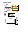
10.0 PGA309DK PC Cable Drawing
Rev 1.5
2/26/2004 8:46:00 AM
Page 42 of 45
Preliminary
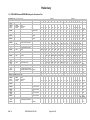
11.0 PGA309DK External EEPROM Settings for Functional Test
8-Bit EEPROM Load >>>>>>>>>>>>>>>>>>>>>>
PGA309 External EEPROM Configuration Data
8
4
2
1
Location '1'
8
4
2
1
8
4
2
Location '0'
1
8
MSB
External
EEPROM
Address
(Decimal)
1/0
MSB/LSB
PGA309
Internal Register
Address
PGA309
Internal Address
Description
3/2
MSB/LSB
5/4
MSB/LSB
7/6
MSB/LSB
Data
Programmed Flag Value
Must be as Shown
Unused
Set to Zero
Unused
Set to Zero
00011
Reference Control & Linearization
7/6
9/8
MSB/LSB
00100
PGA Coarse Offset & Gain / Output
Amp Gain
9/8
11/10
MSB/LSB
00101
PGA Configuration & Over/Under
Scale Limit
11/10
13/12
MSB/LSB
00110
Temperature ADC Control
13/12
4
2
1
LSB
D15
D14
D13
D12
D11
D10
D9
D8
D7
D6
D5
D4
D3
D2
D1
D0
0
1
0
1
0
1
0
0
0
1
0
0
1
0
0
1
5449
0
0
0
0
0
0
0
0
0
0
0
0
0
0
0
0
0000
0
0
0
0
0
0
0
0
0
0
0
0
0
0
0
0
0000
0
0
0
SD
EXS
EXEN
RS
REN
LD7
LD6
LD5
LD4
LD3
LD2
LD1
LD0
0
0
0
0
0
1
0
1
0
0
0
0
0
0
0
0
OWD
GO2
GO1
GO0
GI3
GI2
GI1
GI0
0
0
0
OS4
OS3
0
0
0
1
0
1
1
0
0
0
0
1
0
0
0
1
0
0
CLK_
CFG1
CLK_
CFG0
EXTEN
INTEN
EXTPOL
INTPOL
0
OU EN
HL2
HL1
HLO
LL2
LL1
LL0
0
0
0
0
1
0
1
0
0
1
0
0
0
1
1
1
0
0
ADC2X
ADCS
ISEN
CEN
TEN
AREN
RV1
RV0
M1
M0
G1
G0
R1
R0
0
0
0
0
0
1
1
0
0
0
0
0
0
0
1
OS2 OS1
FFFF - sum(Hex Eq of each location
1/0 thru13/12) truncated above 16 bits Checksum1
8-Bit EEPROM Load >>>>>>>>>>>>>>>>>>>>>>>>>>>>>>>>>>>>>>>>>>>>>>
PGA309 External EEPROM Configuration Data
External
EEPROM
PGA309
PGA309
Address
Internal Register Internal Address
(Decimal)
Address
Description
Data
17/16
Temperature Index Value
MSB/LSB
T0
19/18
Zero Adjustment DAC
MSB/LSB
value for T0 and below
21/20
Gain Adjustment DAC
MSB/LSB
value for T0 and below
23/22
TEND
MSB/LSB
(end of Look-up Table)
25/24
ZME
MSB/LSB
(End of Look-up Table)
27/26
MSB/LSB
Rev 1.5
FFFF - sum(Hex Eq of each location
17/16 thru 24/23) truncated above 16
bits
Checksum2
2/26/2004 8:46:00 AM
1
0
0
0
8
4
2
1
D15
D14
D13
D12
0
0
0
0
0
0
0
1
1
0
0
1
0
0
0
0
0
1
1
4
2
1
8
4
2
D11
D10
D9
D8
D7
D6
D5
D4
1
0
0
0
0
0
0
0
0
0
1
1
0
0
1
0
1
1
1
1
1
1
1
1
1
1
1
1
1
1
1
1
0
0
0
0
0
0
0
0
0
1
0
0
0
1
0
0
Location '1'
8
Page 43 of 45
0
1
0500
OS0
1
SUM =
15/14
MSB/LSB
Hex Eq
1611
0A47
0603
(7FA4)
1
0
0
4
2
1
D3
D2
D1
D0
0
0
0
0
0800
0
0
0
0
0
0640
1
1
1
1
1
1
FFFF
1
1
1
1
1
1
1
7FFF
0
0
0
0
0
0
0
SUM =
0
1
0
1
0
1
1
Location '0'
1
8
805B
Hex Eq
0000
(18E3E)
71C1
Preliminary
PGA309DK IMPORTANT NOTICE
Texas Instruments (TI) provides the enclosed product(s) under the following conditions:
This evaluation kit being sold by TI is intended for use for ENGINEERING DEVELOPMENT OR
EVALUATION PURPOSES ONLY and is not considered by TI to be fit for commercial use. As
such, the goods being provided may not be complete in terms of required design–, marketing–,
and/or manufacturing–related protective considerations, including product safety measures
typically found in the end product incorporating the goods. As a prototype, this product does not
fall within the scope of the European Union directive on electromagnetic compatibility and
therefore may not meet the technical requirements of the directive.
Should this evaluation kit not meet the specifications indicated in the PGA309DK User’s Manual,
the kit may be returned within 30 days from the date of delivery for a full refund. THE
FOREGOING WARRANTY IS THE EXCLUSIVE WARRANTY MADE BY SELLER TO BUYER
AND IS IN LIEU OF ALL OTHER WARRANTIES, EXPRESSED, IMPLIED, OR STATUTORY,
INCLUDING ANY WARRANTY OF MERCHANTABILITY OR FITNESS FOR ANY
PARTICULAR PURPOSE.
The user assumes all responsibility and liability for proper and safe handling of the goods.
Further, the user indemnifies TI from all claims arising from the handling or use of the goods.
Please be aware that the products received may not be regulatory compliant or agency certified
(FCC, UL, CE, etc.). Due to the open construction of the product, it is the user’s responsibility to
take any and all appropriate precautions with regard to electrostatic discharge.
EXCEPT TO THE EXTENT OF THE INDEMNITY SET FORTH ABOVE, NEITHER PARTY
SHALL BE LIABLE TO THE OTHER FOR ANY INDIRECT, SPECIAL, INCIDENTAL, OR
CONSEQUENTIAL DAMAGES.
TI currently deals with a variety of customers for products, and therefore our arrangement with
the user is not exclusive.
TI assumes no liability for applications assistance, customer product design, software
performance, or infringement of patents or services described herein.
Please read the PGA309DK User’s Manual and PGA309 Data Sheet and, specifically, the
Warnings and Restrictions notices in the Manual and Data Sheet prior to handling the product.
This notice contains important safety information about temperatures and voltages. For further
safety concerns, please contact the TI application engineer.
Persons handling the product must have electronics training and observe good laboratory
practice standards.
No license is granted under any patent right or other intellectual property right of TI covering or
relating to any machine, process, or combination in which such TI products or services might be
or are used.
Mailing Address:
Texas Instruments
Post Office Box 655303
Dallas, Texas 75265
Copyright © 2004, Texas Instruments Incorporated
Rev 1.5
2/26/2004 8:46:00 AM
Page 44 of 45
Preliminary
IMPORTANT NOTICE
Texas Instruments Incorporated and its subsidiaries (TI) reserve the right to make corrections,
modifications, enhancements, improvements, and other changes to its products and services at
any time and to discontinue any product or service without notice. Customers should obtain the
latest relevant information before placing orders and should verify that such information is current
and complete. All products are sold subject to TI’s terms and conditions of sale supplied at the
time of order acknowledgment.
TI warrants performance of its hardware products to the specifications applicable at the time of
sale in accordance with TI’s standard warranty. Testing and other quality control techniques are
used to the extent TI deems necessary to support this warranty. Except where mandated by
government requirements, testing of all parameters of each product is not necessarily performed.
TI assumes no liability for applications assistance or customer product design. Customers are
responsible for their products and applications using TI components. To minimize the risks
associated with customer products and applications, customers should provide adequate design
and operating safeguards.
TI does not warrant or represent that any license, either express or implied, is granted under any
TI patent right, copyright, mask work right, or other TI intellectual property right relating to any
combination, machine, or process in which TI products or services are used. Information
published by TI regarding third–party products or services does not constitute a license from TI to
use such products or services or a warranty or endorsement thereof. Use of such information
may require a license from a third party under the patents or other intellectual property of the third
party, or a license from TI under the patents or other intellectual property of TI.
Reproduction of information in TI data books or data sheets is permissible only if reproduction is
without alteration and is accompanied by all associated warranties, conditions, limitations, and
notices. Reproduction of this information with alteration is an unfair and deceptive business
practice. TI is not responsible or liable for such altered documentation.
Resale of TI products or services with statements different from or beyond the parameters stated
by TI for that product or service voids all express and any implied warranties for the associated TI
product or service and is an unfair and deceptive business practice. TI is not responsible or liable
for any such statements.
Mailing Address:
Texas Instruments
Post Office Box 655303
Dallas, Texas 75265
Copyright © 2004, Texas Instruments Incorporated
Rev 1.5
2/26/2004 8:46:00 AM
Page 45 of 45