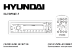
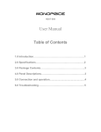
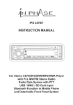
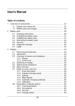
1
Genesis ULTRA Communications / MRI Music System Installation and Operation Manual Index Important Safety Instructions: 2 System Notes: 3 Headset Operation: 4 Technologist Control Unit Operation: Pre Installation: 5, 6 & 7 8 System Parts List: 8, 9 Genesis ULTRA Installation and Connections: 10,11,12, & 13 Rear Panel: 14 Component Locations and Wiring Flow: 15 Installing an older system on a newer GE MRI Magnacoustics Inc™ © 1/2009 rev-s 16, 17 1| Important Safety Instructions CAUTION This installation manual is intended for Qualified Field Service Engineers. If you are not thoroughly familiar with ALL MRI SAFETY REQUIREMENTS, Magnacoustics recommends that you DO NOT ATTEMPT THIS INSTALLATION! 1) Read these instructions. 2) Keep these instructions. 3) Heed all warnings. 4) Follow all instructions. 5) Do not use this apparatus near water. 6) Clean only with a dry cloth. 7) Do not block any ventilation openings. Install in accordance with the manufacturer’s instructions. 8) Do not install near any heat sources such as radiators, heat registers, stoves, or other apparatuses that produce heat. 9) Do not defeat the safety purpose of the polarized or grounding‐type plug. A polarized plug has two blades with one wider than the other. A grounding‐type plug has two blades and a third grounding prong. The wide blade or the third prong is provided for your safety. If the provided plug does not fit into your outlet, consult an electrician for replacement of the obsolete outlet. 10) Protect the power cord from being walked on or pinched, particularly at plugs, convenience receptacles, and the point where they exit from the apparatus. 11) Only use attachments/accessories specified by the manufacturer. 12) Use only with a cart, stand, bracket, or table specified by the manufacturer, or sold with the apparatus. When a cart is used, use caution when moving the cart/apparatus combination to avoid injury from tip‐over. 13) Unplug this apparatus during lightning storms or when unused for long periods of time. 14) Refer all servicing to qualified service personnel. Servicing is required when the apparatus has been damaged in any way, such as power‐supply cord or plug is damaged, liquid has been spilled or objects have fallen into the apparatus, the apparatus has been exposed to rain or moisture, does not operate normally, or has been dropped. 15) Warning ‐ this equipment is not waterproof. To prevent a fire or shock hazard, do not place any container filled with liquid near this equipment (such as a vase or flower pot) or expose it to dripping, splashing, rain or moisture. Warning; This equipment has been certified to comply with the limits for a Class B computing device, pursuant to Subpart J of Part 15 of FCC Rules. Only peripherals certified to comply with the Class B limits may be attached to this equipment. Operation with non‐certified peripherals is likely to result in interference. This equipment generates and uses radio frequency energy and if not installed and used properly, that is, in strict accordance with the manufacturer’s instructions, may cause interference. It has been type tested and found to comply with the limits for a Class B computing device in accordance with the specifications in Subpart J of Part 15 of FCC Rules, which are designed to provide reasonable protection against such interference. Caution; The power switch on this unit will not completely shut off all power from the AC outlet. Since the power cord serves as the main disconnect device for the unit, you will need to unplug it from the AC outlet to shut down all the power. Therefore, make sure the unit has been installed so that the power cord can be easily unplugged from the AC outlet in case of an accident. To avoid fire hazard, the power cord should also be unplugged from the AC outlet when left unused for a long period of time (for example if facility will not be in operation for a few weeks) Magnacoustics Inc™ © 1/2009 rev-s 2| System Notes Our Genesis ULTRA Music System has a number of new features that need to be fully understood to use this system to its full potential Music provides comfort to the patient during the procedure Our yoke style headsets attenuate gradient noise to patient’s ears by 18.1 dB (NRR) DSP technology provides the highest sound quality available for the patient Active volume compensation (Auto Gain) changes volume automatically to mask MR gradient sounds Patient volume and music selection controls with voice feedback for maximum comfort, and versatility Backlit Technologist Control Unit allows operation of the entire system with a touch of the button, even in low light environments Built-in intercom allows the Technologist to communicate directly with the patient even while the scan is in progress Complete AM-FM stereo, multi-disc CD changer Built in interface for Auto Voice and intercom integration all GE MRIs Built in interface for fMRI Built in interface for Video 100 % Microprocessor controlled which simplifies operation and programming. & 26.7 dB @ 1kHz Magnacoustics Inc™ © 1/2009 rev-s 3| Headset Operation EarTip Ear EarC anal Please Note the tops of the Headset rotate In order to provide the highest level of attenuation it is necessary to first, rotate tops of Headset toward the rear of the patients’ head, then while applying pressure rotate fully forward to align with the ear canal as pictured above. It is highly recommended that technologists experiment on themselves to get a feel for this operation. Magnacoustics Inc™ © 1/2009 rev-s 4| Technologist Control Unit Operation Terminology: TCU = Technologist Control Unit 1: To turn Genesis MRI Music ON from TCU push the Green Power button (located on the top right corner). 2: To adjust Technologist’s Speaker Music Level depress the Green TECH VOL+ and the Red VOL– (located to the left of the Power button) for UP and Down respectively. The Stereo will show the level. To Mute the Technologist’s Speakers depress the Violet TECH MUTE button (located under the Red VOL- button). The “ON” will flash on the mid right side of the display in the MUTE box. 3: On power up the microprocessor sets VOL, MIC, and AVC level for patients wherever it was left when the system was turned off. The number equals the percentage of volume and the horizontal bar gives a quick visual representation. 4: Depressing the Violet MIC button (located on bottom left corner) will allow you to override music and talk to the patients. Level can be adjusted buy depressing Green MIC VOL+, or the Red VOL-, for UP and Down respectively. A good starting point is 50. When MIC button is depressed you will see “MIC” on the lower left “MODE” box of the display. 5: When the AVC (intercom integration) input has triggered from depressing the MIC button on your GE Intercom (providing the intercom integration kit was installed) the Display will show AVC in the lower left “MODE” box, and the music to the patient will be interrupted. The AVC level and the console intercom level will control the level to the patients (it’s a good idea adjust the AVC and, leave the console set the same for a Patient without Headsets.) A good starting point is 50 but no two MRIs are the same. 6: Depressing the Blue PAT OVERRIDE button (located above the MIC button) will toggle thru locking out the patient from adjusting the VOL, SEL, VOLSEL, or OFF. This will also be displayed on the lower right “PAT OVR” box. 7: We recommend getting in the habit of depressing the Blue PAT MUTE button (located above PAT OVERRIDE button) after each patient (this way when you are setting up a new patient they will be able to hear you, if the music is on they probably can’t.) 8: Depressing the Green VOL NORM button (located above VOL OFF button) will raise Volume for the Patients to 20. This preset is a good starting point and can be adjusted in program mode described in step 14. 9: Depressing the Green MUSIC VOL- button (located above the VOL NORM button) will lower Volume for the Patients, and depressing the MUSIC VOL+ (located above the MUSIC VOL- button) will raise Volume for the Patients. 10: The Genesis has a feature called AUTO GAIN this provides the ability to automatically adjust volume level of music to Patients dependent on the amount gradient noise being created by MRI. Magnacoustics Inc™ © 1/2009 rev-s 5| Technologist Control Unit Operation 11: Depending on how loud the Scan Sequence is the AUTO GAIN can be turned on and off by depressing the Violet AUTO GAIN button (located under the Red MIC VOL- button). The AUTO GAIN setting can be seen on the upper left corner of the display in the “GAIN” box (Off, Idle, Low, Med, and High). When the AUTO GAIN is active you can also see an ^ to the left of the VOL BAR indicating that it has adjusted the MUSIC LEVEL to the Patient. The percentage can be adjusted to 5%, 10%, 15%, 20%, or 25% per stage in the PROGRAM MODE STEP 14. 12: Depressing the Violet COMP button (located under the Violet AUTO GAIN button) will provide a more even flow of Music to the Patient, by raising the lows and lowering the highs. 13: All the other buttons control the Stereo. 14: Depressing the Blue “PROGRAM” button (located below the red AVC VOL- button) will put the system in “Program Mode. Depressing the MUSIC VOL+ and VOL- button toggle up and down through the Menu respectively. Depressing the Blue and Violet INPUT/ENTER button (located bellow the Blue PROGRAM button) will toggle the options in the menu that is highlighted. Depressing the PROGRAM button again will memorize any changes you have made and exit the Program Mode. (use Page 6 for visual reference of button locations) BOLD text indicates the Default Settings. Tree of programming options: 1.Equalizer: 2. Gain Increment: 3. Gain Dwell Time: 4. Initialization: 5. Volume Norm Set: 6. Volume Gain Set: 7. Bass: 8. Treble: 9. Contrast: 10. Keypad Click: 11. Ambient MIC Level 12. Scan MIC Level 13. Boot Mode 14. FMRI 15. IR Remote 16. IR Remote Dwell YOKE 1 5% 2Sec TUNER 20 LOW LOWEST LOWEST MIN NORM Set Set Norm Pulse High JVC 1Sec YOKE 2 10% 4Sec 6Sec VIDEO FMRI 30 NORM LOW LOW 2, 3,4,5,6 OFF Diagnostic Pulse Low 2Sec 3Sec MAGNAMUFF 15% MAGNAPLUG 20% FLAT 25% XM iPod 40 50 HIGH NORM NORM 7, NORM HIGH HIGHEST HIGH HIGHEST 9,10,11, 12,13,14, High Held Low Held CD MAX 4Sec Magnacoustics Inc™ © 1/2009 rev-s 6| Technologist Control Unit Operation Magnacoustics Inc™ © 1/2009 rev-s 7| Pre Installation Mean Time to Install Allow 3 man-hours for unpacking, installation, checking and setting up of Genesis ULTRA MRI Music System. Additional time may be required when difficult ducting of cables is encountered. Recommended service tools for installation: 1. Nut Driver set 2. Pliers 3. Screw Drivers 4. Razor Knife 6. Electrical Tape 7. 100 ft. Electrical Snake (fish tape) System Parts List Genesis ULTRA is supplied complete with all necessary cables to simplify quick installation. After unpacking, check for the following items: 1: AM/FM Multi-Disc CD Changer. 2: One AM antenna. 3: One FM antenna. 4: Two Speakers. 5: One Transducer Module (houses connections for Headsets, Patient Volume control, Patient selection control, and Mic connection for Active volume stabilization.) 6: One Gradient MIC (Blue cable with BNC and Black Mic.) 7: One Clear Siamese Headset tubing to (Link Transducer to Headset.) 8: Ten Headsets. 9: Patient volume control Red and Green buttons. 10: Patient selection control Blue and Yellow buttons. 11: CB1 - 90 ft. DB9 Female to Male DB9 Cable (Links Genesis Module to Penetration Panel.) 12: CB2 - 50ft. DB9 Female to Female DB9 Cable (Links from Penetration Panel to Transducer.) 13: CB3 - 10ft. DB9 to Male AMP Cable (Links Breakout Box to Genesis Module.) Magnacoustics Inc™ © 1/2009 rev-s 8| System Parts List continued 14: CB4- 3ft DB25 to DB25 Cable (links Breakout Box to AutoVoice board.) 15: CB5- 6ft ¼” to stereo 3.5mm (links the Stereo to Genesis Module.) 16: CB6- 6ft 4 conductor cables (links the speaker terminals on the Stereo to speaker terminals on the Genesis Module.) 17: CB7- 6ft 3.5mm to IR Emitter (connects to Genesis Module and sticks over IR receiver on the Stereo) 18: CB8- 6ft AC Adapter Cable (connects the AC Outlet to the Switched, Voltage Selectable, and Fused AC Receptacle on the rear of Genesis module.) 19: AutoVoice Breakout Box (intercom integration box.) 19: DB9 RF Filter (attaches to penetration panel.) 21: DB9 RF Filter adapter plate (to be used on MRIs that do not have a spare DB9 slot.) 22: Technologist Control Unit (System Remote Control.) 23: Gradient noise sensing Mic (with 10 ft. cable for AGC.) 24: 5 Zip Ties and 5 mounting pads to dress cables. 25: Stereo remote control and 2 AA batteries. 26: Intercom Mic. 27: Genesis Module. Magnacoustics Inc™ © 1/2009 rev-s 9| Genesis ULTRA Installation and Connections Refer to Stereo Manual for Illustrations, and for identification of controls. CAUTION Ensure that AC cords from the Stereo and Genesis module are not connected to power source until all connections are completed. Also ensure that the power entry receptacle is set up for your voltage 110 / 220 Use Page 14 & 15 for J# Illustrations 1: Place Stereo on top of Genesis module, and as close to operator’s console as possible. We recommend either to the left or right of the console. 2: Place Technologist Control Unit on operator’s console and connect cable from Technologist Control Unit to J8 on the rear of Genesis module. 3: Place the speakers on the floor beside the console or other suitable location out of the way. 4: Connect speaker cables to the lower 4 terminals of SPK 1 on the Genesis module. Observe polarity. 5: Connect one side of cable “CB6” 6ft 4-conductor cable to the speaker terminals on the back of the Stereo Red and Black to Left Red and Black, Green and White to Right Black and Red respectively. The other side of cable “CB6” to the upper terminals of SPK1 on the rear of Genesis module. Follow the same colors and polarity as you did with the Stereo. 6: Connect cable “CB7” 6ft 3.5mm to IR Emitter plug to the J7 on the rear of Genesis module. Remove the protective paper from the back of the red IR transmitter and place it over the IR detector that is located about 1/4” to the right of “CD2” label on the JVC MHC Stereo. 7: Connect cable “CB5’ 6ft ¼” to stereo 3.5mm with the ¼” side plugging into the rear of the Stereo and the 3.5mm side into J1 on the rear of Genesis module. 8: Place the Intercom Mic on the Operators Console and plug the cable into J4 on the rear of Genesis module. Turn the MIC on. If you are installing the Intercom Integration Kit follow steps 9 – 13, if not go to step 14 9: Connect the round AMP end of “CB3” 10ft. DB9 to Male AMP Cable to J6 on the rear of Genesis module. 11: Connect the DB9 end of “CB3” to the AutoVoice Breakout Box (intercom integration box silver box with 2 DB25’s and 1 DB9.) 12: Connect one of the DB25 ends of “CB4” (3ft DB25 to DB25 Cable) to the AutoVoice Breakout Box. Magnacoustics Inc™ © 1/2009 rev-s 10 | Genesis ULTRA Installation and Connections continued 13: A. For Horizon LX remove run 788 from J7 on the WIM Module and connect to the open connector on the AutoVoice Breakout Box, then connect the other end of “CB4” to J7 on the WIM. For 5X Console remove the cable going to J9 on the Auto Voice Board and connect to the open connector on the AutoVoice Breakout Box, then connect the other end of “CB4” to J9 on the Auto Voice Board. B. For Excite systems remove Run 1085 labeled OW1-A21-J7 from J7 on the Wim Module and connect to the open connector on the AutoVoice Breakout Box, then connect the other end of “CB4” to J7 on the Wim. For 5X console remove the cable going to J9 on the Auto Voice Board and connect to the open connector on the AutoVoice Breakout Box, then connect the other end of “CB4” to J9 on the Auto Voice Board. 14: Connect the female side of cable “CB8” 6ft AC Adapter Cable to J12 on the rear of Genesis module and DO NOT PLUG INTO AC OUTLET UNTIL ALL CONNECTIONS ARE MADE. Also ensure that the power entry receptacle is set up for proper voltage either 110 or 220. 15: Connect FM and AM Antenna to the Stereo Reference Antenna Connections in the Stereo Instructions for proper installation of FM / AM Antenna Do Not Connect any external Antenna Grounds to the Stereo (A ground loop will be created and you will hear a 60 Hz Hum) If using building Antenna or Cable install a 75 to 300 ohm adapter to eliminate any loops and only connect 1 wire 16: For GE MRI’s remove block off plate from J53 or J52 at penetration panel, all others use supplied kit or fabricate a DB9 slot for filter as required. 17: Install RF filter with female toward computer room. 18: Locate existing electrical conduit between control console and computer room. CAUTION Assistance may be necessary to ensure Trauma free installation of cable CB1 19: Route and install Cable “CB1” (90 ft. DB9 Male to Female) with Female connector toward Genesis Module and Male toward penetration panel. 20: Connect “CB1” Male to the RF filter. 21: Zip tie cable “CB1” to existing supports, or cables from penetration panel to provide strain relief. 22: Connect Female end of cable “CB1” to J11 on the rear of Genesis module. 23: From scan room side of penetration panel connect cable “CB2” (50ft. DB9 Female to Female) to the RF filter you installed on penetration panel. 24: Zip tie cable “CB2” to existing cables from penetration panel to provide strain relief. 25. Route cable “CB2” on opposite side of the cold head (if used) to the front of the MRI utilizing existing conduits. 26: Leave approximately 18 in. of cable “CB2” protruding from the front center of the MRI directly above the table docking mechanism, or alongside the base of the gantry. It is important to locate the end of “CB2” as close as possible to the front center of the bore. Magnacoustics Inc™ © 1/2009 rev-s 11 | Genesis ULTRA Installation and Connections continued 27: Connect cable “CB2” to the Transducer and place it on the pedestal above the Up/Down height control peddles for all GE MRI’s, or locate the Transducer as close as possible to the front center of the bore. 29: There are very sensitive pressure switches located in the Transducer, if pressure builds up even due to a temperature differential the switches might activate causing the volume to go up or down, or music selections to change on their own with no input from the patient. Therefore it is good practice to let the Controls and Transducer sit for a few hours at Scan Room temperature then follow the vent procedure below. Vent the Patient Volume Control and Patient Selection Controls to the atmosphere by pulling the tubing from the nipples on the Transducer one pair at a time (observing polarity for proper synchronization). This also corrects for vacuum or pressure built up from shipping. 30: Connect Gradient noise sensing Mic to the BNC connection on the side of Transducer. Place Mic near the front of the bore. Secure with mounting pad and zip tie. 31: Connect the clear Siamese Headset tubing to the large brass tubes protruding from the top of Transducer. 32: Connect the Headset to unconnected end of clear Siamese tubing. CAUTION: Ensure that all connections are complete before connecting AC power 33: Connect power cord from Stereo to AC receptacle 120V / 15 Amp minimum. 34: Connect the plug side of “CB8” to AC receptacle 120V / 15 Amp minimum. 35: Look at the front panel of the Genesis and ensure the all-8 red LED’s are lit under Circuit A Power and Circuit B Power. If not pull AC Power and contact Magnacoustics Tech Support at 1-800-637-2282 or E-mail at [email protected] for further details. 36: Press the green Power Button on the TCU a self-test should complete and the system should power up in Tuner mode. (It may be necessary to adjust the FM antenna to get better reception. Keep in mind that if the MRI is located in the basement or with most of the transmitting Radio stations separated by the Scan Room, some form of external antenna might be required). Magnacoustics Inc™ © 1/2009 rev-s 12 | Genesis ULTRA Installation and Connections continued 37: After making sure the Stereo is playing ok (with Tuner, Tape or CD selected). Depress the Green VOL NORM button and go into the Scan Room to ensure there is music playing from the Headsets. (If you have help depress the Blue MIC button have them speak into the MIC and ensure you can hear them loud and clear.) 38: In order to set the AUTO GAIN it will be necessary Program the ambient and Full Scan Sound Pressure Levels into the Microprocessor. Depress the PROGRAM button once; depress the MUSIC VOL- button to toggle down till Ambient MIC SET is highlighted. Then depress the INPUT/ENTER button once and then again allowing the Auto Gain Mic to capture and record the (Sound Pressure Level) in the room with the scanner idle. Then depress the MUSIC VOL- once to highlight LOUD MIC SET depress the INPUT/ENTER once, set up a Phantom and start the Scanner for and average scan, then depress the INPUT/ENTER one more time to capture and record the (Sound Pressure Level) of an average Scanner. Then depress the PROGRAM once (which will store the two extremes) and let the Microprocessor calculate when and how much Auto Gain in necessary. Magnacoustics Inc™ © 1/2009 rev-s 13 | Rear Panel Genesis ULTRA J1= Audio Input from Stereo J2= fMRI Input J3= Video Input J4= MIC Input J5= AVC Input J6= fMRI trigger output J7= IR Output to Stereo/TTL PRS output F1, F2, F3, & F4= 4 amp Slow Blow J8= Tech Unit Connector J9= RS232 Spare J10= RS 232 Spare J11= To Transducer “CB1” J12= AC Receptacle 5 amp SB SPK1= Speaker Junction for Mute SPK2= Spare Spk. Junction Magnacoustics Inc™ © 1/2009 rev-s 14 | Component Locations and Wiring Flow Magnacoustics Inc™ © 1/2009 rev-s 15 | Directions for installing or re-installing an older Magnacoustics system on a newer GE MRI If the serial number of your Magnacoustics system is below 18904 and you are installing or reinstalling this system on an; Excite, HD, HDE, HDX, HDXT, MR750 or newer MRI, a cable pinout upgrade might be required. To determine if the upgrade is necessary complete this install according the previous instructions. Depress the GE console Mic button while observing the lower left hand corner of the display on our Technologist Control Unit, “AVC” should appear. If “AVC” does not appear, then the upgrade will be required. (Please Note; Magnacoustics Serial #18904 shipped in July of 2006) Mean Time to Upgrade; Approximately 15 minutes Tools required; #2 Philips Small pin-poker or small screwdriver Please follow the Important Safety Instructions on page 2 and confirm that the power cord is removed from the power entry module before proceeding to Step 1 Magnacoustics Inc™ © 1/2009 rev-s 16 | Directions for installing or re-installing an older Magnacoustics system on a newer GE MRI continued 1. Depress the 4 gray buttons around the upper perimeter of the Genesis Module, releasing the 4 popup tabs on the top of the chassis that conceal the securing screws. 2. Remove the 4 larger screws with the #2 Philips and set aside. 3. The module separates like a clam shell, use an even force pulling up on the top section alternating between the left and right side repeatedly until the top is free and set aside. (Please Note; Be Sure the front face stays with the bottom half of the chassis) 4. Look towards the back right of the chassis, use this pictorial to locate the cable going to J5 remove the molex connector and using pin-poker depress tab to release pins, upgrade / reconfigure to this spec. Located on Back of Chassis Back of Chassis > 12 O'CLOCK 1 3 O'CLOCK 4 6 O'CLOCK 9 O'CLOCK 4 3 2 1 J5 4 3 2 1 J6 ACV IN ^ Con ^ 3 Amp 2 MD18 - DSP - Rev - Front of Chassis 5. Reassemble by reversing steps 3 and 2 then depress the popup tabs on the top of the chassis. 6. Reconnect all wires and confirm that AVC appears in the lower left hand corner of display on our Tech. Unit when the GE console Mic is depressed. 7. If you require any further assistance please contact Magnacoustics Technical Support @ 800-637-2282 (9am to 5pm M-F east coast time). Magnacoustics Inc™ © 1/2009 rev-s 17 |