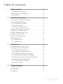
1
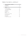
User Manual
Version 1.1
Date: March 2012
Table of contents
1
Getting started
3
1.1 Fingerprint Placement. . . . . . . . . . . . .3
1.2 Instruction for Card Swipe . . . . . . . . . . .3
1.3 Precautions . . . . . . . . . . . . . . . . .3
2
Introduction of device
2.1 Overview of Device Functions
2.2 Important Safeguards . . .
2.2.1 Installation Location . . .
2.2.2 Use of Sensor . . . . . .
2.2.3 Product Appearance . .
2.3 Using the Fingerprint Terminal .
2.4 Date & Time Adjustment . . .
2.5 Enrol Administrator / User . .
2.6 Password Enrolment . . . .
2.7 RFID Card Enrolment . . . .
2.8 Manage Users . . . . . . .
2.9.1 Search Users . . . . . .
2.9.1 Delete User . . . . . . .
3
4
.
.
.
.
.
.
.
.
.
.
.
.
.
.
.
.
.
.
.
.
.
.
.
.
.
.
.
.
.
.
.
.
.
.
.
.
.
.
.
.
.
.
.
.
.
.
.
.
.
.
.
.
.
.
.
.
.
.
.
.
.
.
.
.
.
.
.
.
.
.
.
.
.
.
.
.
.
.
.
.
.
.
.
.
.
.
.
.
.
.
.
.4
.4
.4
.4
.4
.4
.5
.6
.7
.7
.8
.8
.9
User Access
3.1 Description of User Access . . . . . .
3.2 Assign a User to Time Zone . . . . . .
3.2.1 Create a Time Zone . . . . . . .
3.2.2 Assign a Holiday Time Zone . . . .
3.2.3 Create or Edit Group settings . . .
3.2.4 Unlocking Combination settings . .
3.2.5 Change Access Control Parameters
3.2.6 Duress Alarm Parameters . . . . .
3.2.7 Define a Duress Finger . . . . . .
3.2.8 Work Codes . . . . . . . . . .
4
.
.
.
.
.
.
.
.
.
.
.
.
.
Communications
9
.
.
.
.
.
.
.
.
.
.
.
.
.
.
.
.
.
.
.
.
.
.
.
.
.
.
.
.
.
.
.
.
.
.
.
.
.
.
.
.
.9
10
10
11
11
12
12
13
13
14
16
4.1 Network (TCP/IP) . . . . . . . . . . . . . . 16
4.2 RS232/485 . . . . . . . . . . . . . . . . . 16
4.3 Security . . . . . . . . . . . . . . . . . . 17
2
Table of contents...continue 1
4
Communications...continue
17
4.4 Wiegand . . . . . . . . . . . . . . . . . 17
4.5 Web setup . . . . . . . . . . . . . . . . 18
5
System
5.1 System settings . . . .
5.2 Data Management . .
5.2.1 System Update . .
5.3 Keyboard . . . . . .
5.4 Display . . . . . . .
5.5 System Reset. . . . .
5.6 Bell . . . . . . . .
5.7 Miscellaneous settings
5.8 Pendrive (USB) . . . .
5.9 Auto Test . . . . . .
5.10 Record . . . . . .
5.11 System Information .
19
.
.
.
.
.
.
.
.
.
.
.
.
.
.
.
.
.
.
.
.
.
.
.
.
.
.
.
.
.
.
.
.
.
.
.
.
.
.
.
.
.
.
.
.
.
.
.
.
.
.
.
.
.
.
.
.
.
.
.
.
.
.
.
.
.
.
.
.
.
.
.
.
.
.
.
.
.
.
.
.
.
.
.
.
.
.
.
.
.
.
.
.
.
.
.
.
.
.
.
.
.
.
.
.
.
.
.
.
.
.
.
.
.
.
.
.
.
.
.
.
.
.
.
.
.
.
.
.
.
.
.
.
19
19
20
20
20
21
21
22
22
22
23
23
2
1. Getting started
Summary
Recommended fingers: The index finger, middle finger or the ring finger; the thumb and
little finger are not recommended (because they are usually clumsy on the fingerprint
collection screen).
* Please ensure correct
placement of finger on
reader.
1.1 Fingerprint Placement
Please enrol and verify your fingerprint by using the proper finger placement mode. We
shall not be held accountable for any consequences arising out of the degradation in
verification performance due to improper user operations. We shall reserve the right of
final interpretation and revision of this document.
1.2 Instruction for Card Swipe
This device is supplied with an integrated non-contact RFID (125 MHz) card reader module. By offering multiple verification modes such as fingerprint, RF card and fingerprint +
RF card verification, this device can accommodate diversified user needs.
Swipe your card across the sensor area after the voice prompt and remove your card
after the device has sensed it. For the swipe area, please see 2.2.3 Product Appearance.
1.3 Precautions
Protect the device from exposure to direct sunlight or bright light, this greatly affects the
fingerprint collection and leads to fingerprint verification failure.
It is recommended to use the device under a temperature of 0–50°C so as to achieve
the optimal performance. In the event of exposure of the device to the outdoors for
long periods of time, it is recommended to adopt sunshade and heat dissipation facilities because excessively high or low temperature may slow down the device operation
and result in high false rejection rate (FRR).
When installing the device, please connect the power cable after connecting other
cables. If the device does not operate properly, be sure to shut down the power supply
before performing necessary inspections. Note that any live-line working may cause
damage to the device and the device damage arising out of live-line working falls beyond the scope of our normal warranty.
For matters that are not covered in this document, please refer to related materials
including the installation guide, access control software user manual.
3
* Ensure to disconnect all
power cables, before attempting maintenance.
2. Introduction of Device
Summary
2.1 Overview of Device Functions
As an integrated fingerprint & access control device, our product can be connected
with either an electronic lock or an access controller. This device features simple and
flexible operations and supports the use of administrators. The screen displays will guide
you through all the operations. It supports access control function for a security management and supports multiple communication modes.
* Multiple communication
modes
2.2 Important Safeguards
2.2.1 Installation Location
* Do not install in bright light
or direct sunlight.
Do not install terminal in areas which are exposed to bright sunlight or rain, as the fingerprint readers are not designed to work in those areas. Bright light will interfere with
reading of the sensor and fingerprint readers are not waterproof or vandal proof. It is
recommended to protect your fingerprint terminal with enclosure.
2.2.2 Use of Sensor
Do not abuse the fingerprint sensor by scratching the surface, contacting the sensor’s
surface with heat, pressing hard during placement of fingerprint for verification. Clean
the sensor occasionally with cellophane tape to maintain the performance of the sensor.
* Recommended height is
1.2m from the floor
2.2.3 Product Appearance
Front view:
LED indicator
RFID scan area
Selection Keys
LCD Display
Fingerprint sensor
Keypad
Speaker
2.3 Using the Fingerprint Terminal
This chapter will guide on how to use the fingerprint terminal effectively. To get a good
reading every time, initial fingerprint enrollment must be done properly.
4
Summary
The fingerprint terminal provides 4 types of enrolment methods:
•
Fingerprint enrolment
User enrolls his fingerprint template into a terminal and the template will
be used for future verifications.
•
Password enrolment
For user who has difficulty to enrol fingerprint due to poor fingerprint
quality, enrolment of password is recommended. Password enrolment
also suitable for visitors and temporary workers.
•
is
Fingerprint and password enrolment
Under this option, a user can enrol both fingerprint and password at
the same time. The user can either use fingerprint or password to report
tendance or to gain access.
•
at-
RFID card enrolment
Please refer to Chapter 2.7 for RFID Card Function.
2.4 Date / Time Adjustment
When first installing a fingerprint terminal, it is important to set the correct date and time.
* Ensure the correct date &
time on the unit.
Follow the steps shown to access the Date/Time adjustment menu:
•
You can insert inputs into the terminals through the keypad. It contains numbers
from 0-9, an OK button, an ESC/Cancel button, a Scroll up/down button, a doorbell
button and a Menu button.
•
Press
((menu)) once
•
Press
3 times to go to Date/Time
•
Press
once
* Enter the correct date &
time in the required fields
•
Press
to go to the desired field.
•
Enter the value using keypads.
•
Press
once to confirm settings.
5
2.5 Enrol Administrator / User
Summary
Once the fingerprint terminal is switched on, a display on the screen will appear. Enrol a
supervisor or an administrator, who is the in-charge person to administer the fingerprint
templates and the transaction data in the terminal. Choose trustworthy people for this
particular role.
•
Press
(menu) once
•
Press
* Ensure to enrol an administrator on the unit.
(menu) once
* FP = Fingerprint
* PWD = Password / pin
* User = No administrative
rights on the unit
* Admin = Full control of
unit
•
Press
(menu) once
•
Press
•
Press
2 times to enrol fingerprint
* Ensure a good quality
fingerprint
•
Press desired finger 3x times on sensor to enrol
•
Press
once to enrol more
•
Press ESC to exit
6
2.6 Password Enrolment
Summary
If a user cannot enrol his fingerprint, he can choose to use passwords. Follow the steps
below:
* Password may contain
numbers ranging from 1 - 8
digits.
•
Press
3x times to enrol passowrd
•
Type a numeric password in the fileds
•
Press
to enter
2.7 RFID Card Enrolment
If a user cannot enrol his fingerprint, he can choose to use a RFID Card. Follow the steps
below:
•
Press
4x times to enrol a RFID card
•
Confirmation of enrolment
•
Press
•
Press ESC exit
•
Punch the card to enrol
to save OR
7
* RFID card is for added
security on the unit, or if the
user can’t use a fringerprint
2.8 Manage Users
Summary
2.8.1 Search User
* Take note: Only Administrator can edit / delete
users
•
Press
(menu) once
•
Press
•
Press
•
Press
•
Press
•
Select SEARCH USER
•
Press
•
Press
to selected user
•
Type in the desired user id to search
once
(menu) for options window
2.8.2 Delete user
* Ensure to select correct
user ID before deletion
•
Select DEL USER to enter delete options
•
Delete a single user
•
Move down to desired user
•
Press
8
Summary
2.8.2 Delete user...continue
•
Press
(menu) once to select available op-
•
Press
to confirm
tions to delete.
3. User Access
3.1 Description of User Access
Access option function setting is the settings of user’s accessibility to certain doors. It is
known as Time Zone. A combination of Time Zones is known as Group Time Zone. There
are a total of 50 Time Zones available in the reader. Below are some examples of Time
Zone configurations and combinations of Time Zones.
Time Zone 1
* Time Zones can be created for access times to
allow access
Constant access time for a period of one week . Table below is showing the time zone 1
detailed schedule where users are only allowed access from 9am to 6pm from Monday
to Sunday.
Time Zone
1
SUN
09H00 : 18H00
MON
09H00 : 18H00
TUE
09H00 : 18H00
WED
09H00 : 18H00
THU
09H00 : 18H00
FRI
09H00 : 18H00
SAT
09H00 : 18H00
* Access from 9H00 - 18H00
* Everyday of the week
Time Zone 2 & 3
Variation in access for a period of one week . Table below is showing the Time Zone 2
where users are allowed to access from 8am to 12pm from Monday to Friday but denied any access on the weekends and Time Zone 3 where users are allowed to access
from 2pm to 6pm from Monday to Friday but denied any access on the weekends. The
Time Zone 2 and Time Zone 3 belongs to the same group of employees, therefore they
can be grouped together in Group Time Zone, for example Group.
Time Zone
2
3
SUN
23H59 : 00H00
23H59 : 00H00
MON
08H00 : 12H00
14H00 : 18H00
TUE
08H00 : 12H00
14H00 : 18H00
WED
08H00 : 12H00
14H00 : 18H00
THU
08H00 : 12H00
14H00 : 18H00
FRI
08H00 : 12H00
14H00 : 18H00
SAT
23H59 : 00H00
23H59 : 00H00
* TZ 2 : Access from 8H00 to
12H00 during week
* No weekend access
* TZ 3 : Access from 14H00
to 18H00 during week
* No weekend access
9
Summary
Group Time Zones
There are a total of 5 Group Time Zones available for use. Every new registered user belongs to Time Zone 1. Default grouping combination is Group 1 and default Group Time
Zone 1.
GROUP TIME ZONE
1
TIME ZONES
2
3
2
3
4
5
Under a condition where Group 1 and Time Zone 1 are in factory default status, new
registered user defaults in unlocking status. If the grouping of that user does not include
in grouping combination setting, then user can only record time attendance but cannot unlock the door.
3.2 Assign a user to a Time Zone
3.2.1 Create a Time Zone
* Ensure to setup a Time
Zone first before assigning
users
•
Press
•
Press
•
Press
•
Press
•
Press
(menu) once
•
P
Press
once
to select ACCESSS
to selected field and enter values
10
Summary
3.2.2 Assign a Holiday Time Zone
* Ensure to capture all holidays when setting up.
* Recommended to create
holiday time zones to deny
access, rather than deny
access per user for holidays
•
•
•
Press
tto select
l t HOLIDAY
O
SSETTINGS
GS
Insert values
Press
•
Press
to open options window
•
Press
to create a new settings
•
EDIT / DELETE are available to change and
delete
to save
3.2.3 Create or Edit a Access Control Group setting
* Delete is only available
when a new group is created. There must always be
a group active.
•
Press
to select A&C SETTINGS
•
Press
to open options window
•
Note that Time Zone is already available
•
NEW / EDIT / DELETE options are available
11
Summary
3.2.4 Unlocking Combination settings
Combo settings are for extra added security, where more than ons user need to sign in
before access is granted.
* Combo settings for
added security
* 2 or more user verification needed before access
allowed
•
•
Press
to select UNLOCK COMB SETTINGS
•
Press
(menu) for NEW / EDIT / DELETE op-
tions
Press
3.2.5 Change Access Control Parameters settings
* Parameter settings is to
change the control of the
unit
•
Press
•
Press
•
Press
to select ACCESS CONTROL SETTINGS
•
Press
•
Lock (1-10s) :
To adjust the unlocking time after verification.
•
Dsen. Delay (1-99s) :
To delay door sensor from triggering alarm
system when door is not closing. This function
only works when a door sensor is attached to
the reader.
•
Dsen Mode :
To choose the type of door sensor attached to
the reader. There are NO (normally opened)
and NC (normally closed) available. Choose
NONE if no door sensor is attached.
•
Alarm Delay (1-99s) :
To delay the reader from triggering alarm
system.
•
Alarm count (1-9 ti mes ) :
To adjust the maximum verification failures of
users. When the maximum is reached, reader
will trigger alarm system.
•
Close TZ :
Door is always locked during the predefined
time period, so users cannot gain access after
verification.
•
Open TZ :
Door is always unlocked during the predefined
time period, so users do not need to verify their
identities but can gain access.
•
Valid holidays :
Choose Valid to enable the holiday settings.
Choose Invalid to disable the holiday settings.
to save.
to select field
field and change values
12
Summary
3.2.6 Duress Alarm Parameters
The fingerprint reader will trigger alarm system after a duress fingerprint is verified sucessfully. It is advisable :
•
1 to use different fingers to do daily clocking mechanism and to trigger duress alarm
•
2 to use different verification to do daily clocking mechanism and to trigger duress
alarm.
alarm
•
Press
•
Press
•
Press
to select DURESS ALARM SETTINGS
to save
•
Press
to select value field
•
Press
•
Help key :
Select [Yes] to enable. Hold the for 3 second followed
by the fingerprint verification. Successful verification
will trigger alarm system.
•
1:1 Trig :
Select [Yes] to enable. Enter user ID followed by
fingerprint verification to trigger alarm system. During
daily clocking mechanism, all users use 1:N fingerprint
verification. All 1: N fingerprint verification process will
trigger alarm system.
•
1:N Trig :
Select [Yes] to enable. Place finger on scanner for
fingerprint verification to trigger alarm system. During
daily clocking mechanism, all users use 1:1 fingerprint
verification. All 1:N fingerprint verification process will
trigger alarm system.
•
Pwd Trig :
Select [Yes] to enable. Enter user ID and password for
verification to trigger alarm system. During daily clocking mechanism, all users use fingerprint verification.
Any password verification process will trigger alarm
system.
•
Alarm delay :
To delay the reader to trigger alarm system after
verification.
to change options
3.2.7 Define a Duress Finger
If users would like to use different fingers for daily clocking and to trigger duress alarm,
users must enrol with more than 1 fingerprint (2 or above).
•
* Enrol 2x or more fingerprints to assign a fingerprint.
Example : index finger for daily clocking activities and thumb as duress finger.
When duress finger is used for verification, it will trigger alarm system as well. Administrator does not need to enable any of the verification methods in Duress Alarm Parameters.
ers.
13
* Assign index finger for
daily clocking, and thumb
for duress finger.
Summary
Define a duress finger...continue
•
Press
Select user id for change
•
Select ENROL FP
•
Press
•
Follow instructions
•
Select MANAGE
•
ESC to exit
•
Press ESC
•
Press
•
Press
•
Press
•
on USR MNG,
, USER ACCESS
to MANAGE
(menu) once
to exit
to c
3.2.8 Work Codes
This terminal is providing work code feature. The work code feature allows user to key in
predefined number after fingerprint or password verification. User will key in related work
codes to show purpose of their clocking data. Table below is showing examples of work
code function predefined by number:
REASON
WORK CODE
Engineer
100
Welder
200
Packer
300
Receiving
400
Dispatch
500
* Workcodes can be customised.
* Advisable to use software
to adjust workcodes
14
Summary
Create and assign work codes
*Create / Edit workcodes
•
Press
on USR MNG
•
Press
for options window
•
Press
3x times
•
Select NEW to create workcode
•
Press
on WORKCODE
•
Complete the fields
•
EDIT / DELETE available for changes
NOTE :
It is recommended to define work codes
from the software rather than from the
hardware because the process is easier.
•
If you wish to delete confirm with
15
4. Communications
Summary
4.1 Network (TCP/IP)
•
Press
once
•
Press
once
•
Press
•
Press
on NETWORK
* Ensure to assign a static
address, units will not work
on DHCP
•
Press
to desired field, and complete the
values
4.2 RS232 / 485
* Recommended distance
** RS232 = 20m - 60m
*** Could be affected by
distance and power cables
running parallel with unit
cable
** RS485 = 1000m (max)
*** Could be affected by
power cables
•
Press
•
Press
once to select RS232/485
•
Press
•
Press
to select field
to change values
16
4.3 Security
Summary
* Device related password
* Restrict sub-administrator
access
•
Press
•
Press
2x times to select SECURITY
•
Press
to change values
4.4 Wiegand
* Use WIEGAND communication port to connect to
maglock or turnstiles
•
Press
3x times to select WIEGAND
•
Press
•
Press
to desired field and enter values
•
Press
to save
•
Select INPUT OPT
17
Summary
•
Select OUTPUT OPT.
•
•
Press
Press
to select fields
to change values or enter
values
4.5 Web Setup
•
Press
to select WEB SETUP
•
Fill in the fields as requested
•
Press
to select fields to change values
18
5. System
Summary
5.1 System settings
•
Press
once
•
Press
2x times to select SYSTEM
•
Press
to scroll down to fields
•
Change values
•
Press
to enter SYSTEM SETTINGS
•
Press
on a delete function
•
Press
to confirm
5.2 Data Management
•
Press
to select DATA MNG
19
Summary
5.2.1 System Update
* System update - ensure
to have latest firmware
loaded on USB before this
function will activate
•
•
Press
Press
to select desiired option
•
Insert PENDRIVE(USB) with latest firmware on,
before accessing this function
to confirm
Key
5.3 Keyboard
* Custom “F” keys to diffirentiate between access
modes
•
Press
•
Press
3x times to select KEYBOARD
•
Press
to edit selected field
•
Press
to select field
•
Press
•
Press
5.4 Display
•
Press
•
Press
to select DISPLAY
to change values
to save
20
5.5 System Reset
Summary
* Reset function are only
configuration of unit, and
not to delete users
•
Press
•
Press
to select RESET
•
Select field that needed to be reset
•
Press
to confirm
5.6 Bell
* Notification bell for time
breaks (lunch / tea / etc)
•
Press
•
Press
•
P
Press
2x times to select BELL
tto change
h
values
l
or enter
t
values
•
Press
•
•
P
Press
tto edit
dit th
ld
the field
Display will indicate change with a BELL in the
STATE field
to save
21
5.7 Miscellaneous settings
Summary
* Ensure device settings are
correct when installing the
device
•
•
P
Press
3
3x ti
times tto select
l t MISC SET
•
Press
to change the value of the
desired field or enter text
Press
5.8 Pendrive (USB)
* Pendrive / USB can be
used to upload and download user ID’s
•
Select PENDRIVE on the MAIN MENU
•
Insert a PENDRIVE (USB) and select desired
option
5.9 Auto
u Test
* Ensure to run a AUTOTEST
to test all functions on unit
•
Select AUTO TEST on the MAIN MENU
•
Select the desired field for testing
22
Summary
•
Ensure to see the image of you finger print (see
image left). This indicates that the sensor is in
working condition.
•
P
Press
tto select
l t sensor ttestt
•
Test accordingly (see note on right hand side)
•
Press
to save
5.10 Record
•
Select RECORD on the MAIN MENU
•
Select option to run desired query on
•
Press
•
RECORD screen
5.11 System Information
•
Select SYS INFO on the MAIN MENU
to select desired info page
23
Summary
•
DEVICE info screen
•
POWER iinfo
f screen
5.11.1 Number of Password Users Available in the Terminal (Password User)
Users can do verification using PIN password and a combination of fingerprint and password. To find out how many users are using password:
•
Press Menu > Sys Info > Password User > View the number
5.11.2 Number of Time Scanners Have Been Used for Verification (S Logs)
S logs stands for scanner logs, which means the number of times the scanner has been
used for verification, regardless of whether it is successful or not. To view the scanner
logs:
•
Press Menu > Sys Info > Record > Amount of transactions USED / FREE
5.11.3 Free Space Information (Free Space)
Find out the information about availability of space in your terminal through this function.
•
Press Menu > Sys Info > Free Space > Free = number available
5.11.4 Device Information (Dev Info)
Find out the information about your terminal through this function. Press Menu > Sys Info
> Dev Info > View the info
Information available includes:
•
AttLog (10k): Shows the number of attendance logs that can be stored in the terminal, for example for AttLog (10k) 12 means 10,000 x 12 = 120,000
•
S Logs: Shows the number of Scanner Logs available for the terminal.
•
Manufactured Time (Manu Time): The date and time when the terminal was produced is displayed when you press Manu Time
•
Serial Number of the Terminal (Serial Num): The Serial number is pasted on the back
of the terminal but in case the sticker is damaged, this is where you can retrieve the
serial number.
•
Manufacturer: Get the name of the manufacturer of the terminal here.
•
Device Name: All models have different names. If you don’t know the name of the
terminal that you are having, get it here.
•
Algorithm Version: This is where you can find terminal’s algorithm version.
24
•
Firmware Version: Support sometimes require a firmware version to resolve some
support issues. The version and date of the version is released is provided here. For
example: Ver 6.20 Aug 19 2009
•
View MAC: This feature is a security feature of the products. Linking Software to the
terminal requires the correct MAC address. Without availability of MAC address,
the software will not be activated correctly. All products are supplied with the correct MAC address to ease communication. This is also to hinder people from using
the software with a different hardware brand. An example of a MAC address is
00:0A:5D F1 BE 57.
•
Press Menu > Sys Info > Dev Info > View MAC
25
Summary
Appendix A:
TXD
RXD
GND
WD 1
WD 0
RJ45-1
RJ45-2
}
}
RS 232
GND
}
Wiegand Out
485 A
BELL +
BELL BEEP
RJ45-6
}
GLED
IWD 0
IWD 1
}
Bell
COM 2
NO 2
NC 1
Output
RLED
Ethernet
RJ45-3
}
NC 2
}
COM 1
NO 1
Wiegand In
Door Sensor
}
485 B
RS 485
S900 Pinout
BUT
GND
}
}
Alarm
Lock
}
Button
}
Power In
SEN
+ 12V
GND