1
MICROWAVE OVEN
CK135 (WHITE)
SERVICE
M anual
CON TEN TS
M ICROWAV E OV EN
1. Precaution
2. Specifications
3. Operating Instructions
4. Disassembly and Reassembly
5. Alignment and Adjustments
A ut o
1min+
A ut o
/
GB/ F/ D/ E/ I/ NL/ R
/C
6. Troubleshooting
Auto
7. Exploded Views and Parts List
8. PCB Diagrams
9. Schematic Diagrams
PRECAUTIONS TO BE OBSERVED BEFORE AND DURING
SERVICING TOAVOID POSSIBLE EXPOSURE TO EXCESSIVE
MICROWAVE ENERGY
(a) Do not operate or allow the oven to be
operated with the door open.
(b) Make the following safety checks on
all ovens to be serviced before
activating the magnetron or other
microwave source, and make repairs as
necessary:
(1) Interlock operation,
(2) proper door closing,
(3) seal and sealing surfaces (arcing,
wear, and other damage),
(4) damage to or loosening of hinges
and latches,
(5) evidence of dropping or abuse.
(c) Before turning on microwave power
for any service test or inspection
within the microwave generating
compartments, check the magnetron,
wave guide or transmission line, and
cavity for proper alignment, integrity,
and connections.
(d) Any defective or misadjusted
components in the interlock, monitor,
door seal, and microwave generation
and transmission systems shall be
repaired, replaced, or adjusted by
procedures described in this manual
before the oven is released to the
owner.
(e) A Microwave leakage check to verify
compliance with the Federal
performance standard should be
performed on each oven prior to
release to the owner.
Samsung Electronics
1. Precaution
Follow these special safety precautions. Although the microwave oven is completely safe during ordinary
use, repair work can be extremely hazardous due to possible exposure to microwave radiation, as well as
potentially lethal high voltages and currents.
1-1 Safety precautions (
)
1. All repairs should be done in accordance
with the procedures described in this
manual. This product complies with
Federal Performance Standard 21 CFR
Subchapter J (DHHS).
2. Microwave emission check should be
performed to prior to servicing if the oven is
operative.
3. If the oven operates with the door open :
Instruct the user not to operate the oven and
contact the manufacturer and the center for
devices and radiological health immediatly.
4. Notify the Central Service Center if the
microwave leakage exceeds 5 mW/cm2
5. Check all grounds.
6. Do not power the MWO from a "2-prong"
AC cord. Be sure that all of the built-in
protective devices are replaced. Restore any
missing protective shields.
7. When reinstalling the chassis and its
assemblies, be sure to restore all protective
devices, including: nonmetallic control
knobs and compartment covers.
8. Make sure that there are no cabinet openings
through which people--particularly
children--might insert objects and contact
dangerous voltages. Examples: Lamp hole,
ventilation slots.
9. Inform the manufacturer of any oven found
to have emmission in excess of 5 mW/cm2,
Make repairs to bring the unit into
compliance at no cost to owner and try to
determine cause.
Instruct owner not to use oven until it has
been brought into compliance.
CENTRAL SERVICE CENTER
10. Service technicians should remove their
watches while repairing an MWO.
Samsung Electronics
11. To avoid any possible radiation hazard,
replace parts in accordance with the wiring
diagram. Also, use only the exact
replacements for the following parts:
Primary and secondary interlock switches,
interlock monitor switch.
12. If the fuse is blown by the Interlock Monitor
Switch: Replace all of the following at the
same time: Primary, door sensing switch
and power relay, as well as the Interlock
Monitor Switch. The correct adjustment of
these switches is described elsewhere in this
manual. Make sure that the fuse has the
correct rating for the particular model being
repaired.
13. Design Alteration Warning:
Use exact replacement parts only, i.e.,
only those that are specified in the
drawings and parts lists of this manual.
This is especially important for the
Interlock switches, described above.
Never alter or add to the mechanical or
electrical design of the MWO. Any design
changes or additions will void the
manufacturer's warranty.10.Always unplug
the unit's AC power cord from the AC
power source before attempting to
remove or reinstall any component or
assembly.
14. Never defeat any of the B+ voltage
interlocks. Do not apply AC power to the
unit (or any of its assemblies) unless all
solid-state heat sinks are correctly installed.
15. Some semiconductor ("solid state") devices
are easily damaged by static electricity. Such
components are called Electrostatically
Sensitive Devices (ESDs). Examples include
integrated circuits and field-effect
transistors.
Immediately before handling any
semiconductor components or assemblies,
drain the electrostatic charge from your
body by touching a known earth ground.
16. Always connect a test instrument's ground
lead to the instrument chassis ground before
connecting the positive lead; always remove
the instrument's ground lead last.
1-1
Pretaution
1-2 Special Servicing Precautions (Continued)
17. When checking the continuity of the witches
or transformer, always make sure that the
power is OFF, and one of the lead wires is
disconnected.
18. Use replacement components that have the
same ratings, especially for flame resistance
and dielectric strength specifications. A
replacement part that does not have the
same safety characteristics as the original
might create shock, fire or other hazards.
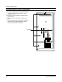
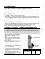
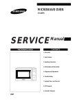
1-3 Special High Voltage Precautions
1.
High Voltage Warning
Do not attempt to measureany of the high
voltages--this includes the filament voltage
of the magnetron. High voltage is present
during any cook cycle.
H. V. Capacitor
Before touching any components or wiring,
always unplug the oven and discharge the
high voltage capacitor (See Figure 1-1)
2.
The high-voltage capacitor remains charged
about 30 seconds after disconnection. Short
the negative terminal of the high-voltage
capacitor to to the oven chassis. (Use a
screwdriver.)
3.
High voltage is maintained within specified
limits by close-tolerance, safety-related
components and adjustments. If the high
voltage exceeds the specified limits, check
each of the special components.
H. V. Diode
Short
Touch chassis ground first then short to the high
voltage capacitor terminal by using screwdriver or
jumper wire.
Fig. 1-1. Discharging the High Voltage Capacitor
PRECAUTION
PRECAUTION
Never touch any circuit wiring with your hand nor with
uninsulated tool during operation.
There exists HIGH VOLTAGE ELECTRICITY with high
current capabilities in the circuits of the HIGH VOLTAGE
TRANSFORMER secondary and filament terminals. It is
extremely dangerous to work on or near these circuits
with the oven energized.
DO NOT measure the voltage in the high voltage circuit
including filament voltage of magnetron.
PRECAUTION
Servicemen should remove their watches whenever
working close to or replacing the magnetron.
-3-
2. Specifications
2-1 Table of Specifications
ITEM
M ODEL
CK135
TIM ER
99 M INUTES
POWER SOURCE
230V/ 50HZ, AC
POWER CONSUM PTION
M ICROWAVE : 1,500W,GRILL : 1,300W, CONVECTION : 1700W
OUTPUT POWER
FROM 100 TO 900W (6 LEVEL POWER)
(IEC-705 TEST PROCEDURE)
OPERATING FREQUENCY
2,450M Hz
M AGNETRON
OM 75PH(31)
COOLING M ETHOD
COOLING FAN M OTOR
OUTSIDE DIM ENSIONS
625(W) x 390(H) x 575(D)
NET WEIGHT
26 Kg
SHIPPING WEIGHT
28 Kg
Samsung Electronics
2-1
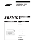
3. Operating Instructions
3-1 Control Panel
Display
Aut o
Auto Defrost Feature Selection
Start / Cooking Time Adjustment Button
1min+
Aut o
Auto Reheat & Cook Feature Selection
/
GB/ F/ D/ E/ I/ NL/ R
Language Mode Selection
Standing Time Setting
Convection Mode / Temperature Selection
/C
Grill Mode Selection
Microwave / Power Level Mode Selection
Preheat Mode Selection
Combined Mode Selection (Microwave + Grill)
Auto
Combined Mode Selection (Microwave + Convection)
Turntable ON/OFF
Stop / Cancel Button
Clock Setting
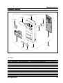
3-2 Features & External Views
Door
Ventilation Holes
Light
Safety Interlock Holes
A ut o
1m in+
A ut o
/
GB/ F/ D/ E/ I/ NL/ R
/C
Control Panel
Auto
Guide Roller
Glass Plate
Door Latches
Coupler
A ut o
1min+
A ut o
/
GB/ F/ D/ E/ I/ NL/ R
320mm
Grill Rack
/C
Auto
231.5 mm
401.5 mm
556 mm
3-1
544.5 mm
Samsung Electronics
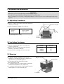
4. Disassembly and Reassembly
4-1 Replacement of Magnetron, Motor Assembly and Lamp
Remove the magnetron including the shield case,
permanent magnet, choke coils and capacitors (all
of which are contained in one assembly).
Cover Air
Thermo S/ W
Lamp
1. Disconnect all lead wires from the magnetron
and lamp.
2. Remove the bracket mounting.
3.Remove the magnetron supporter
4. Remove the air cover.
5. Remove screws securing the magnetron to the
wave guide.
6. Take out the magnetron very carefully.
7. Remove screws from the back panel.
8.Remove the assy noise filter.
9. Take out the fan motor.
10. Remove the oven lamp by pulling out from
hole of air cover carefully.
Fan M otor
M agnetron
NOTE1: When removing the magnetron, make
sure that its antenna does not hit any
adjacent parts, or it may be damaged.
NOTE2: When replacing the magnetron, be sure
to remount the magnetron gasket in
the correct position and make sure the
gasket is in good condition.
H. V. Trans
Screw
H. V. Capacitor
4-2 Replacement of High Voltage Transformer
1. Discharge the high voltage capacitor.
2. Disconnect all the leads.
3. Remove the mounting bolts.
4. Reconnect the leads correctly and firmly.
PRECAUTION
Servicemen should remov their w atches w henever
w orking close to or replacing the magnetron.
PRECAUTION
There exists HIGH VOLTAGE ELECTRICITY w ith high
current capabilities in the circuits of the HIGH
VOLTAGE TRANSFORM ER secondary and filament
terminals. It is extremely dangerous to w ork on or
near these circuits w ith the oven energized.
DO NOT measure the voltage in the high voltage
circuit including filament voltage of magnetron.
Samsung Electronics
4-1
- MEMO-
4-2
Samsung Electronics
Disassembly and Reassembly
4-3-6 Reassembly Test
After replacement of the defective component parts of the door, reassemble it and follow the instructions below for proper
installation and adjustment so as to prevent an excessive microw ave leakage.
1. When mounting the door to the oven, be sure to adjust the door parallel to the bottom line of the oven face
plate by moving the upper hinge and lower hinge in the direction necessary for proper alignment.
2. Adjust so that the door has no play between the inner door surface and oven front surface. If the door
assembly is not mounted properly, microwave energy may leak from the space between the door and
oven.
3. Do the microwave leakage test.
4-4 Replacement of Fuse
1. Disconnect the oven from the power source.
2. When 15A fuse blows out by the operation of interlock monitor switch failure, replace the primary
interlock switch, door sensing switch, monitor switch and power relay.
3. When the above three switches operate properly, check if any other part such as the control circuit board,
blower motor or high voltage transformer is defective.
4-5 Replacement of Drive Motor
1. Take out the glass tray and guide roller from the
cavity.
2. Turn the oven upside down to replace the drive motor.
3. Remove a screw securing the drive motor cover.
Drive M otor
Screw
4. Disconnect all the lead wires from the drive motor.
5. Remove screws securing the drive motor to the
cavity.
6. Remove the drive motor and coupler.
7. When replacing the drive motor, be sure to
remount it in the correct position with the
coupler.
8. Connect all the leads to the drive motor.
Drive M otor Cover
Base Plate
9. Screw the drive motor cover to the base plate
with a screw driver.
Samsung Electronics
4-3
Disassembly and Reassembly
4-6 Replacement of Control Circuit Board
1. Be sure to disclyarge any static electricity from
your body, and avoid touching the "Touch
control" clrcuitry.
2. Disconnect the connectors from the control
circuit board.
3. Remove screws securing the control circuit
bord.
4. Lift up the control circuit board from right side
and remove the hooks holding the contol
circuit board to the box assembly.
SCREWS
4-4
Samsung Electronics
5. Alignment and Adjustments
PRECAUTION
1. High voltage is present at the high voltage terminals during any cook cycle.
2. It is neither necessary nor advisable to attempt measurement of the high voltage.
3. Before touching any oven components or w iring, alw ays unplug the oven from its pow er source and discharge the high voltage
capacitor.
5-1 High Voltage Transformer
1. Remove connectors from the transformer terminals
and check continuity.
2. Normal resistance readings are as follows:
Secondary
Filament
Primary
Filament Terminals
98.6Ω ± 10%
Show s Continuity
1.44Ω ± 10%
(Room temperature = 20˚C)
Primary
Terminals
5-2 Low Voltage Transformer
1. The low voltage transformer is located on the
control circuit board.
2. Remove the low voltage transformer from the
PCB Ass'y and check continuity.
3. Normal resistor reading is shown in the table.
Terminals
Resistance
1~2(Input)
3~4(Output)
5~6(Output)
290Ω
4.0Ω
1.0Ω
5-3 Magnetron
1. Continuity checks can indicate only an open
filament or a shorted magnetron. To diagnose an
open filament or shorted magnetron :
2. Isolate the magnetron from the circuit by
disconnecting its leads.
3. A continuity check across the magnetron filament
terminals should indicate one ohm or less.
4. A continuity check between each filament terminal
and magnetron case should read open.
M agnetron Antenna
Gasket Plate
Cooling Fins
Samsung Electronics
5-1
Alignment and Adjustments
5-4 High Voltage Capacitor
1. Check continuity of the capacitor with the meter set at the highest resistance scale.
2. Once the capacitor is charged, a normal capacitor shows continuity for a short time, and then indicates 9MΩ.
3. A shorted capacitor will show continuous continuity.
4. An open capacitor will show constant 9MΩ.
5. Resistance between each terminal and chassis should read infinite.
5-5 High Voltage Diode
1. Isolate the diode from the circuit by disconnecting its leads.
2. With the ohm-meter set at the highest resistance scale, measure across the diode terminals. Reverse the
meter leads and read the resistance. A meter with 6V, 9V or higher voltage batteries should be used to
check the front-to back resistance of the diode (otherwise an infinite resistance may be read in both
directions). The resistance of a normal diode will be infinite in one direction and several hundred KΩ in
the other direction.
5-6 Main Relay and Power Control Relay
1. The relays are located on the PCB Ass'y. Isolate them from the main circuit by disconnecting the leads.
2. Operate the microwave oven with a water load in the oven. Set the power level set to high.
3. Check continuity between terminals of the relays after the start pad is pressed.
5-7 Adjustment of Primary Switch, Door Sensing Switch and Monitor Switch
Precaution
For continued protection against radiation hazard, replace parts in accordance w ith the w iring diagram and be sure to use the
correct part number for the follow ing sw itches: Primary and door sensing sw itches, and the interlock monitor sw itch (replace all
together). Then follow the adjustment procedures below . After repair and adjustment, be sure to check the continuity of all
interlock sw itches and the interlock monitor sw itch.
1. When mounting Primary switch and Interlock
Monitor switch to Latch Body, consult the
figure.
Primary Interlock Sw itch
2. No specific adjustment during installation of
Primary switch and Monitor switch to the latch
body is necessary.
3. When mounting the Latch Body to the oven
assembly, adjust the Latch Body by moving it so
that the oven door will not have any play in it.
Check for play in the door by pulling the door
assembly. Make sure that the latch keys move
smoothly after adjustment is completed.
Completely tighten the screws holding the Latch
Body to the oven assembly.
4. Reconnect to Monitor switch and check the
continuity of the monitor circuit and all latch
switches again by following the components test
procedures.
5. Confirm that the gap between the switch
housing and the switch actuator is no more than
0.5mm when door is closed.
5-2
Interlock M onitor
Sw itch
Lever Sw itch
Body Latch
Primary sw itch
M onitor sw itch (COM -NC)
Door Sensing S/ W
Door Sensing
Sw itch
Door Open
Door Closed
∞
0
∞
0
∞
0
Samsung Electronics
Alignment and Adjustments
5-8 Output Power of Magnetron
CAUTION
MICROWAVE RADIATION
PERSONNEL SHOULD NOT ALLOW EXPOSURE TO M ICROWAVE RADIATION FROM M ICROWAVE GENERATOR OR OTHER PARTS
CONDUCTING M ICROWAVE ENERGY.
The output power of the magnetron can be measured by performing a water temperature rise test.
Equipment needed :
* Two 1-liter cylindrical borosilicate glass vessel (Outside diameter 190 mm)
* One glass thermometer with mercury column
NOTE: Check line voltage under load. Low voltage will lower the magnetron output. Make all temperature
and time tests with accurate equipment.
1. Fill the one liter glass vessel with water.
2. Stir water in glass vessel with thermometer, and record glass vessel's temperature ("T1", 10±1˚C).
3. After moving the water into another glass vessel, place it in the center of the cooking tray. Set the oven to high
power and operate for 48seconds exactly. (1.5 seconds included as a holding time of magnetron oscillation:)
4. When heating is finished, stir the water again with the thermometer and measure the temperature ("T2").
5. Subtract T1 from T2. This will give you the water temperature rise. (∆T)
6. The output power is obtained by the following formula;
Output Power =
4.187 x 1000 x ∆T+0.55xMcx(T2-T0)
46.5
46.5: Heating Time (sec)
4.187 : Coefficient for Water
1000 : Water (cc)
∆T : Temperature Rise (T2-T1)
Mc : Cylindrical borosilicate glass weight
To : Room temperature.
7. Normal temperature rise for this model is 9˚C to 11˚C at 'HIGH'.
NOTE 1: Variations or errors in the test procedure will cause a variance in the temperature rise.
Additional power test should be made if temperature rise is marginal.
NOTE 2: Output power in watts is computed by multiplying the temperature rise (step 5) by a factor of 90
times the of centigrade temperature.
Samsung Electronics
5-3
Alignment and Adjustments
5-9 Procedure for Measurement of Microwave Energy Leakage
1) Pour 275±15cc of 20±5˚C(68±9˚F) water in a
beaker which is graduated to 600cc, and place
the beaker in the center of the oven.
2) Start to operate the oven and measure the
leakage by using a microwave energy survey
meter.
3) Set survey meter with dual ranges to 2,450MHz.
4) When measuring the leakage, always use the 2
inch spacer cone with the probe. Hold the probe
perpendicular to the cabinet door. Place the
spacer cone of the probe on the door and/or
cabinet door seam and move along the seam, the
door viewing window and the exhaust openings
moving the probe in a clockwise direction at a rate of 1 inch/sec. If the leakage testing of the cabinet door
seam is taken near a corner of the door, keep the probe perpendicular to the areas making sure that the
probe end at the base of the cone does not get closer than 5cm to any metal. If it gets closer than 5cm,
erroneous readings may result.
5) Measured leakage must be less than 4mW/cm2, after repair or adjustment.
A ut o
1min+
A ut o
/
GB/ F/ D/ E/ I/ NL/ R
/C
Auto
M aximum allow able leakage is 5mW/ cm2.
4mW/ cm2 is used to allow for measurement and meter accuracy
5-10 Check for Microwave Leakage
1. Remove the outer panel.
2. Pour 275±15cc of 20±5˚C(68±9˚F) water in a
beaker which is graduated to 600cc, and
place the beaker in the center of the oven.
3. Start the oven at the highest power level.
4. Set survey meter dual ranges to 2,450MHz.
5. Using the survey meter and spacer cone as
described above, measure arnear the
opening of magnetron, the surface of the air
guide and the surface of the wave guide as
shown in the following photo.( but avoid the
high voltage components.) The neading
should be less than 4mW/cm2.
WARNING
AVOID THE HIGH VOLTAGE COM PONENTS.
5-11 Note on Measurement
1) Do not exceed the limited scale.
2) The test probe must be held on the grip of the handle, otherwise a false reading may result when the
operator's hand is between the handle and the probe.
3) When high leakage is suspected, do not move the probe horizontally along the oven surface; this may
cause damage to the probe.
4) Follow the recommendation of the manufacturer of the microwave energy survey meter.
5-12 Leakage Measuring Procedure
5-12-1 Record keeping and notification after measurement
1) After adjustment and repair of a radiarion preventing device, make a repair record for the measured
values, and keep the data.
2) If the radiation leakage is more than 4 mW/cm2 after determining that all parts are in good condition,
functioning properly and the identical parts are replaced as listed in this manual notift that fact to ;
CENTRAL SERVICE CENTER
5-12-2 At least once a year have the microwave energy survey meter checked for accuracy by its manufacturer.
5-4
Samsung Electronics
6. Troubleshooting
PRECAUTION
1. CHECK GROUNDING BEFORE CHECKING FOR TROUBLE.
2. BE CAREFUL OF THE HIGH VOLTAGE CIRCUIT.
3. DISCHARGE THE HIGH VOLTAGE CAPACITOR.
4. WHEN CHECKING THE CONTINUITY OF THE SWITCHES OR TRANSFORM ER, DISCONNECT ONE LEAD WIRE FROM THESE
PARTS AND THEN CHECK CONTINUITY WITHOUT THE POWER SOURCE ON. TO DO OTHERWISE M AY RESULT IN A FALSE
READING OR DAM AGE TO YOUR M ETER.
5. DO NOT TOUCH ANY PART OF THE CIRCUIT OR THE CONTROL CIRCUIT BOARD, SINCE STATIC DISCHARGE M AY DAM AGE IT.
ALWAYS TOUCH GROUND WHILE WORKING ON IT TO DISCHARGE ANY STATIC CHARGE BUILT UP.
6-1 Electrical Malfunction
SYMPTOM
CAUSE
CORRECTIONS
Oven is dead.
Fuse is OK.
No display and no operation at all.
1. Open or loose lead w ire harness
2. Open thermal cutout (M agnetron)
3. Open low voltage transformer
4. Defective Ass'y PCB
Check fan motor when thermal cutout is defective.
No display and no operation at all.
Fuse is blow n.
1. Shorted lead w ire harness
2. Defective primary latch sw itch (NOTE 1)
3. Defective monitor sw itch (NOTE1)
4. Shorted HVCapacitor
5. Shorted HVTransformer (NOTE2)
Check adjustment of primary, interlock monitor,
pow er relay, door sensing sw itch.
Check Ass'y PCB w hen LVT is defective.
NOTE 1: All of these sw itches must be replaced at the same time.
(refer to adjustment instructions)
Check continuity of pow er relay contacts and if it has continuity, replace pow er
relay also.
NOTE 2: When HVTransformer is replaced, check diode and magnetron also.
Oven does not accept
key input (Program)
Timer starts countdow n but no
microw ave oscillation.
(No heat w hile oven lamp and
fan motor turn on.)
Samsung Electronics
1. Key input is not in-Sequence
2. Open or loose connection of membrane
key pad to Ass'y PCB
3. Shorted or open membrane panel
4. Defective Ass'y PCB
1. Off-alignment of latch sw itches
2. Open or loose connection of high voltage
circuit especially magnetron filament
circuit
NOTE: Large contact resistance w ill bring
low er magnetron filament voltage and
cause magnetron to low er output and/ or
intermittent oscillation.
3. Defective high voltage components
H.V.Transformer
H.V.Capacitor
H.V.Diode,H.V.Fuse
M agnetron
4. Open or loose w iring of pow er relay
5. Defective primary latch sw itch
6. Defective pow er relay or Ass'y PCB
Refer to operation procedure.
Replace PCB main.
Adjust door and latch sw itches.
Check high voltage component according to
component test procedure and replace if it is
defective.
Replace PCB main.
6-1
Troubleshooting
6-2 Electrical Malfunction(continued)
SYMPTOM
CAUSE
CORRECTIONS
Oven lamp and fan motor turn on
1. M isadjustment or loose w iring
of primary latch sw itch
2. Defective primary latch sw itch
Adjust door and latch sw itches.
Oven can program but timer
does not start.
1. Open or loose w iring of secondary
interlock sw itch
2. Off-alignment of primary interlock
3. Defective secondary interlock S/ W
Adjust door and interlock sw itches.
M icrow ave output is low ;.
Oven takes longer time to
cook food.
1. Decrease in pow er source voltage.
2. Open or loose w iring of magnetron
filament circuit. (Intermittent oscillation))
3. Aging of magnetron
Consult electrician.
Fan motor turns on w hen plugged in
Loose w iring of door sensing sw itch
Check w ire of door sensing sw itch.
Oven does not operate and return
to the plugged in mode.
Defective Ass'y PCB
Replace PCB main.
Loud buzzing noise can be heard.
1. Loose fan and fan motor
2. Loose screw s on H.V.Transformer
3. Shorted H.V.Diode
Tighten screw s of fan motor.
Tighten screw s of H.V.Transformer.
Replace H.V.Diode.
Turntable motor does not rotate.
1. Open or loose w iring of turntable motor.
2. Defective turntable motor.
Check the w ire of turntable motor
Replace turntable motor.
Oven stops operation during cooking
1. Open or loose w iring of primary
interlock sw itch
2. Operation of thermal cutout(M agnetron)
Adjust door and latch sw itches.
Sparks
1. M etallic w are or cooking dishes
touching on the oven w all.
2. Ceramic w are trimmed w ith gold or
silver pow der also causes sparks.
Inform the customer.
Do not use any type of cookw are w ith
metallic trimming.
Uneven cooking
Uneven intensity of microw ave due to
its characteristics.
Wrap thinner parts of the food w ith
aluminum foil.
Use plastic w rap or cover w ith a lid.
Stir once or tw ice w hile cooking
foods such as soup, cocoa, or milk.
Noise from the turntable motor
w hen it starts to operate.
Noise may result from the motor.
Replace turntable motor.
6-2
Samsung Electronics
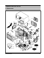
7. Exploded Views and Parts List
7-1 Exploded Views
MM52
MM73
MM01
MM67
MM582
MM62
MC22
MM66
MM61
MM68
MM63
MM07
MM69
MM72
MM59
MM171
MM65
MM55
MM60
MM05
MM57
MM53
MM03
MM35
MM21
MM06
MD01
MM71
MM17
MC01
MM58
MM25 MM10
MM16
MM08
MB01
MM56
MM28
MM22
MM102
NC
MB05
NO
COM
MB03
MM88
MB02
MM14
MM29
MM09
MB04
MM18
MM30
MM19
MM641
MM31
MM20
MM32
MM27
Samsung Electronics
MM33
MM93
MM642
7-1
Exploded View s and Parts List
7-2 Main Parts List
CK135/XEF
No.
MB01
MB02
MB03
MB04
MB05
MM01
MM03
MM05
MM06
MM07
MM08
MM09
MM10
MM102
MM14
MM16
MM17
MM171
MM18
MM19
MM20
MM21
MM22
MM25
MM27
MM28
MM29
MM30
MM31
MM32
MM33
MM35
MM52
MM53
MM55
MM56
MM57
MM58
MM581
MM59
MM60
MM61
MM62
MM63
MM641
MM642
7-2
Part Code
DE93-20020D
3405-000175
3405-000178
DE66-90054B
DE66-40021B
DE70-30002W
DE39-00173A
DE96-00011C
DE31-00001D
DE39-00022B
OM75PH(31)ESS
DE71-00062A
4713-001046
DE63-00023A
DE26-00008A
DE71-60461A
DE47-20009A
DE47-20009A
DE74-20002A
DE92-90189B
DE67-60082A
DE39-40409A
DE31-10170A
DE65-20014A
DE61-40065A
DE80-10002G
2501-001107
DE61-50106A
DE59-40001A
DE91-70061A
DE26-20152A
DE32-10013A
DE63-90035I
DE64-00131A
3601-000448
DE62-00009A
DE61-50027B
DE62-90099A
DE71-00066A
DE71-60386A
DE63-20017A
DE47-70031G
DE61-70060A
DE61-30006A
DE97-00136D
DE97-00136C
Description
ASSY BODY LATCH
SWITCH-MICRO
SWITCH-MICRO
LEVER-SWITCH
LATCH-BODY
PANEL-OUTER
WIRE HARNESS-A
ASSY NOISE FILTER
MOTOR-FAN
ASSY POWER CORD
ASSY-MAGNETRON
COVER-AIR
LAMP-INCANDESCENT
CUSHION-HVT
TRANS-H.V
COVER-CEILING
THERMOSTAT
THERMOSTAT
TRAY-COOKING
ASSY-GUIDE ROLLER
COUPLER
WIRE HARNESS-E
MOTOR-SYNCHRONOUS
CABLE CLAMP
FOOT
BASE-PLATE
C-OIL
BRACKET-HVC
DIODE-H.V
ASSY-H.V.FUSE
TRANS-L.V
SENSOR-THERMISTOR
CUSHION-RUBBER
FILM-LAMP
FUSE-CARTRIDGE
ADIABATIC-RIGHT
BRACKET-HEATER
ADIABATIC-COVER
COVER-ADIABATIC-R
COVER-BACK
GASKET-HEATER
HEATER-GRILL
SPRING-PLATE
SUPPORTER-HEATER
ASSY-WIRE RACK
ASSY-WIRE RACK
Specification
Q'ty Remark
M959/XSA,-,-,-,1
250V,15A,200gf,SPST-NO
1
250V,15A,200gf,SPST-NO
2
NYLON#66(2021SW),40G,M959/XSA,
1
NYLON#66(2021SW),40g,M959/XSA,
1
PCM,T0.6,-,-,P-WHT,CK135,1
230V50Hz,CK135,-,-,-,-,-,-,-,-,-,-,1
SN-3WED,250V10A,3W NO-INRUSH TC,-,-,-,1
-,SMF-2D3EA,230V50Hz,-,M1D33CE/XSA.RAD,-,2320rpm
1
4819D,CK135,230V50Hz,-,-,-,-,1
OM75PH(31)ESS
1
NYLON#66,-,-,-,-,CK135T,1.3-CONV
1
240V,104mA,25W,ORG,-,-,25x62mm
1
-,EPDM,T25.5,W30,L50,-,CK135,HS75
1
SHV-293EC,230V50HZ,2230V/3.15V,-,DY
1
MICA,T0.3,W114.2,L117.5,-,3RD1
PW2N-520PB,160/60,250V/7.5A,H,
1 CAVITY-UPPER
PW2N-520PB,160/60,250V/7.5A,H,
1
GLASS,T6,PI360,1.2CUFT,NEG,-,1
D16.5,STD,-,-,-,1
PPS,T5.3XL24.1,-,BRN,3RD-W(1.3),MW7896W,- 1
230V50HZ,M9G45,CTW,-,-,1
M2LJ24Z702,ST-16F,220/240V,2.5
1
DA-6N,NY-66,-,-,-,-,-,1 P-CORD
PP,BLK,T2x22x17mm,-,-,4
SGCC,T0.8,W404,L633,CK135,1
1.1uF,2.1KV,BK,54x35x85,20mm
1
SECC,T0.8,W31,L125.8,-,-,1
HVR-1X-32B-12,-,-,-,-,1
THV060T-0800-H,5KV/0.80A,WHT
1
SLV-105E,230V,50HZ,AC17V/3V,-,
1
PT-312-K2,-,-,-,-,-,1
DFA20,T1.5,W190,L100,BLK,JE154
1 OUTER-P
PET,W74xL105,T0.11,CK135,1
250V,10A,SLOW-BLOW,CERAMIC,6.35x31.8mm 1
T3.0,W173.5,L247,CK135,SUPER FINE INSULATIO,1
SECC,T1.0,W51,L55,CE945GF,-,1
T15,W290,L377,CE115K,-,-,-,1
SECC,T0.6,-,-,-,CK135T,1.3-CONV
1
SCP3,T0.6,W275,L385.5,BLK-COAT
1
BRASS,T1.5,OD30.5,ID22.5,-,-,1
D6.6,230V1280W,M9G45,SJH,-,-,1
SK-5,T0.5,-,-,-,-,1
ALUMINA,5G,2ND-W/P,-,-,-,1
CK135,HIGH-RACK,-,1
CK95,LOW-RACK,-,-,-,1
-
Samsung Electronics
Exploded Views and Parts List
7-2 Main Parts List
CK135/XEF
No.
MM65
MM66
MM67
MM68
MM69
MM71
MM72
MM88
MM93
MC22
Part Code
DE72-60035R
DE61-50570B
DE61-00068A
DE60-40009B
DE61-50021A
DE61-50490A
DE61-50347A
DE73-90027A
DE60-60025A
DE39-00174A
Samsung Electronics
Description
GUIDE-AIR
BRACKET-AIR GUIDE
BRACKET-UPPER
WASHER-TEFLON
BRACKET-FLANGE
BRACKET-TCO
BRACKET-EARTH
FERRITE-CORE
PIN-FOOT
WIRE HARNESS-B
Specification
SECC,T0.5,-,-,-,CK135,SECC T0.8,CK95,SECC,T0.6,-,-,-,CK135T,SLOT,ID22.2,OD28,T1.2,TEFLON,SECC1,T0.8,32,32,-,-,SECC1,T0.6,34,58,-,-,BSS2-A,T1.0,W35,L43,MBGF45,-,NI-ZN,T13.8,W21.0,L28.0,BNF-14
PP-JI350,BLK,-,-,-,-,-,230V50Hz,CK135,-,-,-
Q'ty Remark
1
2
1
1
1
1
1
1
4
1
-
7-3
Exploded View s and Parts List
7-3 Door Parts List
M D08
M D04
M D06
M D17
M D09
M D02
M D07
M D10
CUSHON DOOR
TAPE-DOUBLE FACE
M D01
M D15
CK135/XEF
No.
MD01
MD02
MD04
MD06
MD07
MD08
MD09
MD10
MD15
MD17
7-4
Part Code
DE94-00298A
DE64-00084A
DE94-00300A
DE64-00087A
DE61-00103A
DE61-80002A
DE61-80003A
DE64-40264B
DE64-00085A
DE67-00061B
Description
ASSY DOOR
DOOR-A
ASSY DOOR-E
DOOR-C
SPRING-KEY
HINGE-UPPER
HINGE-LOWER
DOOR-KEY
DECORATION-DOOR
SCREEN-DOOR(B)
Specification
Q'ty
CK135T,P/WHT,1.3 CONVECTION
1
PC(141R),-,-,-,WHT(80409),CE135T,-,-,1
CK135T,BLK,SEALING
1
PBT,-,-,-,1.3-CONV,CK135T,-,-,BLK
1
CK135,HSWR,D6.0,-,L32.8,27 3/4,-,T0.8,BLUING,-,-1
SCP1,T2.3,26,77,ZPC3,WHT,CE945
1
SCP1,T2.3,26,77,ZPC3,WHT,CE945
1
NYLON#66(2021SW),40G,-,M959/XS
1
PC(141R),-,-,-,-,WHT(80409),-,CK135T,-,-,1
CK138F/XEF,GLASS,-,W260.5,L422.5,-,1
Remark
-
Samsung Electronics
Exploded Views and Parts List
7-4 Control Parts List
MC03
MC06
MC10
MC28
MC15
MC07
MC32
MC01
MC13
MC27
MC33
CK135/XEF
No.
MC01
MC03
MC06
MC07
MC10
MC13
MC15
MC27
MC28
MC32
MC33
Part Code
DE94-00299A
DE72-00078A
DE67-00045A
RC-135T-00
DE64-00123A
DE94-00318A
DE67-00060A
DE67-00055A
DE67-00047A
DE97-00137A
DE97-00139A
Samsung Electronics
Description
ASSY CONTROL-BOX
CONTROL-PANEL
WINDOW-DISPLAY
ASSY PCB PARTS:CK135
KNOB-COVER
ASSY CONTROL-PANEL
BUTTON-START
BUTTON-CANCEL
BUTTON-DEFROST
ASSY-BUTTON SELECT
ASSY-BUTTON CLOCK
Specification
-,CK135T,P/WHT,1.3 CONVECTION
PC(141R),CK135T,-,-,-,-,WHT(80409),SAN,T2,W69.6,-,SMOG,CK135T,-,-,-,CK135T,-,-,-,CONVECTION,-,CK135,P/WHT,-,-,WHT,CK135T,-,P.C CLEAR,-,-,-,CK135T,-,-,PC(141R),-,-,WHT(80409),CK135T,-,-,CK135T,P/WHT,-,-,-,CK135T,P/WHT,-,-,-,-
Q'ty
1
1
1
1
1
1
1
1
1
1
1
Remark
-
7-5
Exploded Views and Parts List
7-5 Casing Parts List
MM80
MM94
MM74
MM173
MM76
MM75
MM57
MM83
MM751
MM81
MM77
MM82
MM78
MM73
CK135/ XEF
No.
MM100
MM173
MM73
MM74
MM75
MM751
MM76
MM77
MM78
MM81
MM82
MM83
7-6
Part Code
DE60-40014B
DE47-20009A
DE92-90478K
DE31-10171A
DE31-90019A
DE31-90020A
DE47-70077A
DE60-30016B
DE60-40026A
DE62-00008A
DE72-30016B
DE92-90487A
Description
WASHER-C MOTOR
THERMOSTAT
ASSY-CASING
MOTOR-CONVECTION
BLADE-FAN
BLADE-FAN
HEATER-CONVECTION
NUT-FLANGE
WASHER-PLAIN
ADIABATIC-CASING
BUSH-MOTOR
ASSY-COVER CASING
Specification
Q'ty Remark
M16,T1.0,SECC,ZNC3,-,-,-,-,1
PW2N-520PB,160/60,250V/7.5A,H,
1 CK135T,COVER-CASING,-,-,-,1
SMC-105EA,230V/50HZ,2800RPM,-,
1
SECC,T0.6,-,-,-,-,1
ALSTAR,T0.6,W250,L250,-,-,1
230V,1680W,30.7,7,-,-,-,-,1
M4,MSWR10,FEFN,-,-,-,-,-,1
ID5.5,OD12,T1.0,SBC1,-,-,-,-,1
T3.0,W241,L336.8,CK135,SUPER FINE INSULATIO,- 1
MSWR3,D5.6,L15.7,CE115K,ZP3,-,
1
CE115K,230V50HZ,-,-,-,1
-
Samsung Electronics
Exploded View s and Parts List
7-6 Standard Parts List
CK135/ XEF
Part Code
DE60-10012A
DE60-10012A
DE60-10012A
DE60-10018A
DE60-10034A
DE60-10045A
DE60-10080B
DE60-10080B
DE60-10082H
DE60-10082H
DE60-10082H
DE60-10082H
DE60-10082H
DE60-10082H
DE60-10082H
DE60-10082H
DE60-10082H
DE60-10082H
DE60-10082H
DE60-10082H
DE60-10082H
DE60-10098A
DE60-10122A
DE60-10122A
DE60-20063A
DE60-20063A
DE60-30016A
DE60-10045A
DE60-10061A
DE60-10122A
DE60-10045A
DE60-10122A
DE60-10088A
DE60-10082H
DE60-10098A
DE60-10012A
Description
SCREW-TAP TITE
SCREW-TAP TITE
SCREW-TAP TITE
SCREW-ASSY MACHINE
SCREW-TH
SCREW-TAP PH
SCREW-WASHER
SCREW-WASHER
SCREW-A
SCREW-A
SCREW-A
SCREW-A
SCREW-A
SCREW-A
SCREW-A
SCREW-A
SCREW-A
SCREW-A
SCREW-A
SCREW-A
SCREW-A
SCREW-ASSY TAP TITE
SCREW-TAP TH
SCREW-TAP TH
BOLT-FLANGE
BOLT-FLANGE
NUT-FLANGE
SCREW-TAP PH
SCREW-TAP TH
SCREW-TAP TH
SCREW-TAP PH
SCREW-TAP TH
SCREW-TAP PH
SCREW-A
SCREW-ASSY TAP TITE
SCREW-TAP TITE
Samsung Electronics
Specification
TH,+,3,M4,L10,SWR10,ZPC2,TOOTH
TH,+,3,M4,L10,SWR10,ZPC2,TOOTH
TH,+,3,M4,L10,SWR10,ZPC2,TOOTH
PH,M4X0.7P,8,MSWR10,SN1,WS,-,TH,+,M4,L10,STS304,-,-,-,-,PH,M3,L6,FEFZY,-,-,-,-,-,PH,PI5,L10,SWRCH18A,ZP2,2S,-,PH,PI5,L10,SWRCH18A,ZP2,2S,-,2S-4X12,TOOTHED,-,-,-,-,-,-,-,
2S-4X12,TOOTHED,-,-,-,-,-,-,-,
2S-4X12,TOOTHED,-,-,-,-,-,-,-,
2S-4X12,TOOTHED,-,-,-,-,-,-,-,
2S-4X12,TOOTHED,-,-,-,-,-,-,-,
2S-4X12,TOOTHED,-,-,-,-,-,-,-,
2S-4X12,TOOTHED,-,-,-,-,-,-,-,
2S-4X12,TOOTHED,-,-,-,-,-,-,-,
2S-4X12,TOOTHED,-,-,-,-,-,-,-,
2S-4X12,TOOTHED,-,-,-,-,-,-,-,
2S-4X12,TOOTHED,-,-,-,-,-,-,-,
2S-4X12,TOOTHED,-,-,-,-,-,-,-,
2S-4X12,TOOTHED,-,-,-,-,-,-,-,
PH,TC,M4X8,SWRCH18A,ZPC2,GLD,W
TAP,TH,2-4X8,FE,FN,-,-,-,-,TAP,TH,2-4X8,FE,FN,-,-,-,-,M4,10,ZPC3,YEL,MSWR,-,-,-,M4,10,ZPC3,YEL,MSWR,-,-,-,M4,MSWR10,-,-,-,-,-,-,PH,M3,L6,FEFZY,-,-,-,-,-,TH,M4,L8,STS,-,-,-,-,-,TAP,TH,2-4X8,FE,FN,-,-,-,-,PH,M3,L6,FEFZY,-,-,-,-,-,TAP,TH,2-4X8,FE,FN,-,-,-,-,PH,M3,L8,FEFZY,PLAIN,-,-,-,-,2S-4X12,TOOTHED,-,-,-,-,-,-,-,
PH,TC,M4X8,SWRCH18A,ZPC2,GLD,W
TH,+,3,M4,L10,SWR10,ZPC2,TOOTH
Q'ty
1
1
1
2
1
1
4
4
5
1
3
1
2
2
1
2
2
2
1
2
5
2
2
1
2
2
1
1
3
2
1
4
8
2
1
1
Remark
N-F-EA
P-C-EA
S-M-EA
B/EATH
SENSOR
MG-TCO
MGT
TNS-HV
B-PLTE
BKT/AIR
BKT/UP
C/AIR
C/BLOW
C/CASING
CN-BOX
CO-A/RIG
CV/BACK
GRILL/TCO
GUIDE-AI
LATCH
PN-OUT
M/DRIV
BKT/HEA
C-CEIL
HI-LOW
HI-UPP
SENSOR
B/MORT
SUPP-HEA
CV-CAS
ASSY-PCB
LVT
HVD
-
7-7
8. P.C.B Diagrams
8-1 P.C.B Diagrams
8-1
Samsung Electronics
P.C.B Diagrams
8-2 P.C.B Parts List
CK135/ XEF
Part Code
0201-000280
3501-001062
3501-001068
3501-001155
3601-001126
DE07-10096A
DE09-00108A
DE30-20016A
DE34-00063A
DE47-40024A
DE61-90048D
DE92-00469A
0401-001083
0402-001103
0403-001288
0501-000465
0504-000130
0504-000159
0601-001467
1202-000141
1404-001194
2001-001102
2001-003132
2007-000277
2007-000300
2007-000468
2007-000572
2007-000671
2007-000868
2007-000931
2007-000941
2203-000260
2203-000444
2203-000555
2203-001608
2401-000244
2401-000466
2401-000598
2401-000911
2401-002075
2401-002438
2401-002598
2801-003933
3404-001129
3711-000999
3711-001038
3711-004142
3711-004143
DE39-60001A
DE41-00131A
Description
ADHESIVE-TS
RELAY-POWER
RELAY-POWER
RELAY-MINIATURE
FUSE-CARTRIDGE
V.F.DISPLAY
IC-MCU
BUZZER
SWITCH-PRESSURE
HOLDER-FUSE
HOLDER-DIGITRON
ASSY PCB AUTO
DIODE-SWITCHING
DIODE-RECTIFIER
DIODE-ZENER
TR-SMALL SIGNAL
TR-DIGITAL
TR-DIGITAL
LED
IC-VOLTAGE COMP.
THERMISTOR-PTC
R-CARBON(S)
R-CARBON(S)
R-CHIP
R-CHIP
R-CHIP
R-CHIP
R-CHIP
R-CHIP
R-CHIP
R-CHIP
C-CERAMIC,CHIP
C-CERAMIC,CHIP
C-CERAMIC,CHIP
C-CERAMIC,CHIP
C-AL
C-AL
C-AL
C-AL
C-AL
C-AL
C-AL
CRYSTAL-UNIT
SWITCH-TACT
CONNECTOR-HEADER
CONNECTOR-HEADER
CONNECTOR-HEADER
CONNECTOR-HEADER
WIRE-SO COPPER
P.C.B-MAIN
Samsung Electronics
Specification
Q'ty
SA-33P-2,RED,950+-110(PS)
0
24VDC,523.2mW,16A,1FormA,15mS,
1
24Vdc,523mW,16A,1FormA,15mS,10
2
24VDC,200MW,3000MA,1FORMA,10MS,10MS 5
250V,1.6A,FAST-ACTING,CERAMIC,5x20mm 1
SVM-07MM09,GRN/ORG,7DIG,112seg
1
TMP87PM14F,OTP-32K,QFP,8BIT-64PIN,-,-,-,- 1
CBE2220BA,STICK,-,-,-,-,-,-,1
DAIL,28VDC,10mA,24,-,JES1424GS
1
FH-51H,7.5A,-,-,-,-,1
NYLON#66,10G,BLK,-,-,-,-,-,1
230V50Hz,VFD,RC-135T-00,CK135T
1
MM4148,100V,150MA,LL-34,TP
18
1T4,400V,1A,TS-1,TP
4
ZMM55C5V1,4.8-5.4V,500MW,LL-34,TP
3
MMBT3904,NPN,225mW,SOT-23,TP,3
1
KSR1105TF,NPN,200MW,4.7K/10K,SOT-23,TP 11
KSR2105,PNP,200MW,4.7K/10K,SOT-23,TP
1
CHIP,RED,1.4x1.25mm,640nm
1
7033,SOT-89,3P,-,SINGLE,0V,-,P
1
39ohm,20%,220/240V,270Vac,1.2A,-,TP
1
200OHM,5%,1/2W,AA,TP,2.4X6.4MM
3
620ohm,5%,1/2W,AA,TP(26mm),2.4
2
100KOHM,1%,1/10W,DA,TP,2012
1
10KOHM,5%,1/10W,DA,TP,2012
8
1KOHM,5%,1/10W,DA,TP,2012
7
220OHM,5%,1/10W,DA,TP,2012
1
2KOHM,5%,1/10W,DA,TP,2012
1
4.7KOHM,1%,1/10W,DA,TP,2012
1
470OHM,5%,1/10W,DA,TP,2012
3
47KOHM,5%,1/10W,DA,TP,2012
7
10nF,10%,50V,X7R,TP,2012
2
1nF,10%,50V,X7R,TP,2012,3
0.02nF,5%,50V,NP0,TP,2012
2
22nF,+80-20%,50V,Y5V,TP,2012
5
100uF,20%,10V,GP,TP,6.3x7,5
1
10uF,20%,35V,GP,TP,5x7,5
1
1uF,20%,50V,GP,TP,4x7,5
1
22uF,20%,16V,GP,TP,5x7,5
2
4.7uF,20%,50V,GP,TP,5x11,5
1
47uF,20%,50V,WT,TP,6.3x11,5
1
220uF,20%,50V,GP,TP,10x16,5
1
8MHz,50ppm,28-AAA,12pF,70ohm,TP
1
12VDC,50mA,160gf,6.6x6.6x7mm,14
BOX,5P,1R,2.5mm,STRAIGHT,SN
1
BOX,6P,1R,2.5mm,STRAIGHT,SN
1
BOX,3P/5P,1R,5mm/2.5mm,STRAIGH
1
BOX,2P/3P,1R,5mm/2.5mm,STRAIGH
1
PI0.6,SN,T,52MM,TAPING_WIRE,-,
45
RC-135T-**,FR-1,-,-,-,T1.6*90*262,-,-,-,1
Remark
RY06
RY07,08
RY01~05
FUSE1
VFD1
IC01
BUZ1
ECD1
FUSE1
D04~06,08~22
D01,02,03,07
ZD01,02,03
TR07
TR01~03,05,06,08~13
TR04
LD01,02
IC02
PTC1
R03,04,05
R22,23
R33
R08~10,12,13,16,17
R06,07,15,18,19,31,35
R11
R14
R32
R01,02,20
R24~30
C12,13
C18,19,20
C08,09
C04,05,07,10,16
C03
C11
C17
C06,15
C14
C02
C01
XTL1
SW01~14
CN03
CN04
CN01
CN02
J04~10,12~49
-
8-2
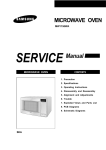
9. Schematic Diagrams
9-1 Schematic Diagrams
MAGNETRON
HIGH VOLTAGE
DIODE
FA
TO CHASSIS
F
HIGH VOLTAGE CAPACITOR
RED
RED
RED
H.V.FUSE
BLU
BRN
RED
SYMBOL COLOR
BRN BROWN
BLK
BLACK
RED
RED
BLU
BLUE
HIGH VOLTAGE
TRANSFORMER
9-1
Samsung Electronics
ELECTRONICS
© Samsung Electronics Co., Ltd. M ay 2000
Printed in Korea
Code No. : DE68-01193A