1
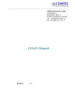
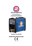
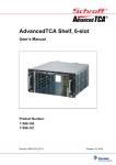
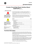
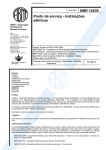
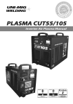
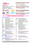
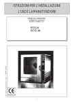
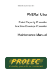
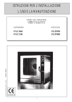
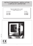
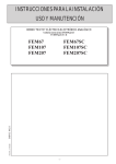
COMTEL Electronics GmbH Technopark I / Bretonischer Ring 11 D-85630 Grasbrunn / Germany Tel: +49 (0)89 43 77 89 - 0 Fax: +49 (0)89 43 77 89 - 77 CO14N Service Manual Revision: 1.1 Revision History Rev 1.0 1.1 Date November 2011 December 2011 Description Initial version Minor Changes Author Dmitry Tsitsilin Dmitry Tsitsilin Copyright Notice This material is the proprietary property of Comtel Electronics. Copying, compilation, modification, distribution or any other use whatsoever of this material is strictly prohibited without written permission of Comtel Electronics GmbH. The information in this document is subject to change without notice and should not be construed as a commitment by Comtel Electronics. Neither Comtel Electronics, nor there agents assume any responsibility for the use or reliability of this document or the described software. Page 2 of 20 Table of Contents 1 2 3 4 SHELF ARCHITECTURE.......................................................................... 5 TECHNICAL SPECIFICATION ............................................................... 7 SHELF LABELING ..................................................................................... 8 SHELF INSTALLATION............................................................................ 9 4.1 4.2 4.3 4.4 5 6 7 SHELF GROUNDING ............................................................................... 12 LOGIC GROUND ...................................................................................... 13 SYSTEM MAINTENANCE ...................................................................... 14 7.1 7.2 7.3 7.4 7.5 7.6 8 MOUNTING THE SHELF ....................................................................................... 9 CONNECTING POWER CORDS ............................................................................. 10 CRIMPING INSTRUCTION.................................................................................... 10 POWERING THE SHELF ...................................................................................... 11 REPLACING PEM .............................................................................................. 14 REPLACING FUSES ............................................................................................. 15 MAINTAINING AIR FILTERS ............................................................................... 15 REPLACING FAN TRAY ...................................................................................... 16 REPLACING SHELF MANAGER ........................................................................... 18 REPLACING SHELF FRU AND TELCO ALARMS BOARD ...................................... 19 GETTING STARTED WITH SHELF MANAGEMENT ...................... 20 Caution - Read this manual before working on this unit. Caution - HAZARDOUS VOLTAGE! Contact may cause electric shock or burn. Electronic components are sensitive to static electricity. All electronic boards in this shelf are protected by Shelf Ground. It is recommended that anti-static wrist straps be worn and connected to a known ground connection when removing any Field Replaceable Unit in this shelf. Page 3 of 20 Caution - Rotating fan blades. Can cause minor injury or cut. Keep hands clear when servicing. Allow time for fan blades to slow to a stop before fully removing. Caution – Heavy object. To avoid muscle strain or back injury, use lifting aids and proper lifting techniques when removing or replacing. Reference Documents PICMG® 3.0 AdvancedTCA® Base Specification Comtel CO14N User Manual Revision R3.0 Revision 2.3 Page 4 of 20 1 Shelf Architecture 1 2 3 4 5 10 10 6 7 9 1. Blower [FT1] 2. Blower [FT2] 3. Blower [FT3] 4. Blower [FT4] 5. High Speed Backplane 6. Power Backplane 8 7. Air Filter Frame 8. Temperature Sensor Board 9. ESD Wrist Strap Terminal (Banana Jack) 10. Rack handles Caution – Heavy object. To avoid muscle strain or back injury, use lifting aids and proper lifting techniques when removing or replacing. Caution – Rack Handles cannot carry the weight of fully loaded shelf. Use them rather to slide the shelf out of the rack. Page 5 of 20 15 16 17 11 12 18 13 14 11. Power Entry Module (PEM1) 12. Power Entry Module (PEM2) 13. Shelf Manager (ShMC1) 14. Shelf Manager (ShMC2) 15. Shelf FRU and Telco Alarms Board (SFRU1) 16. Shelf FRU and Telco Alarms Board (SFRU2) 17. ESD Wrist Strap Terminal (Banana Jack) 18. Shelf Ground Terminals This unit contains electronic components that are sensitive to static electricity. All electronic boards in this shelf are protected by Shelf Ground. It is recommended that anti static wrist straps be worn and connected to a known good shelf ground connection when servicing any electronic components. Page 6 of 20 2 Technical Specification Power Specification: 2 redundant PEMs Input Voltage operating range -36VDC — -72VDC Current ratings: 105Amps@48VDC and 84Amps@60VDC Backplane Topology: Dual Star Triple Replicated Full Mesh 40G support on Fabric interface Cooling Capability: Pull Cooling Scheme 300W+/ Front Board 35W+/ RTM Certifications: UL listed, CE, NEBS (designed to be compliant) Shelf Management: Pigeon Point SHMM500 shelf manager Intelligent Fan Trays (IPMC based) Intelligent PEMs (IPMC based) Intelligent Fan Trays (IPMC based) Intelligent Shelf FRU and Telco Alarms Board (IPMC based) Dimensions and weight: Weight W (no ears) W H D D (cable trays) Unpackaged 38 kg 84 lbs 435 mm 17.1 in 483 mm 19.0 in 577 mm 22.7 in 500 mm 19.7 in 573 mm 22.6 in Packaged (on pallet) 50 kg 110 lbs 620 mm 24.4 in 880 mm 34.7 in 840 mm 33 in - Page 7 of 20 3 Shelf Labeling Shelf Nameplate: Model name: CO14N Manufacture Part Number (optional) Serial Number (optional) Nominal input voltage and current Country of manufacture Certification signs/marks Shelf Serial Number label: Model number (full), example: CO14N-B-DS-UB4-S2128-P2-T2-A Mfg Part Number with Code-39 Bar code Serial Number with Code-39 Bar code Page 8 of 20 4 Shelf Installation 4.1 Mounting The Shelf Improper installation might cause system damage or personnel injury. Consider the following guidelines: Install the system only in area with restricted access Follow the installation rules governs in your country Power distribution to the shelf must include over current protection devices Use appropriate protective bonding conductor according to over current limits for power lines Make sure that the personnel will not interfere with cables and cords connected to the rack/shelf Make sure that the shelf airflow i.e. ventilation openings are not disturbed by cables and rack construction (see below) otherwise it might lead to system damage. Caution – Use front and rear filler blades to block the airflow in empty slots. Note – Remove battery saver on shelf manager before using the shelf. Note – Remove protective film from shelf surfaces after mounting in a rack. Page 9 of 20 4.2 Connecting power cords To connect external power supply to the shelf two-hole lugs (3/4” = 19 mm) must be used. Use Thomas & Betts PN 256-30695-1225 as shown below Rubber boots are supplied with the shelf. Use these to cover power lugs. WARNING - Always disconnect input power prior to servicing PEM. Disturbed current through the backplane connector will lead to high voltage spikes or arc discharge thus connector/backplane damage. Note - caution must be taken when working near to the PEM power studs to avoid personnel injury. The shelf operating voltage range covers TNV-2 voltages (60-80V). This voltage is considered hazardous. Caution – Double Pole Fusing. When replacing a fuse – replace also the complementary one (see Section 7.2). 4.3 Crimping Instruction Before crimping, slide rubber boot along each wire (red on “-” and black on “+”). Follow the guidelines: Strip the insulation from cable to the length shown in table (on reverse side). Be careful not to nick cable strands which may later result in stands breaking Cable end should be clean: wire brush or clean with emery cloth if necessary. Insert cable into connector until it stops. The insertion length must approximate the stripped length of cable Insert connector in die and compress between the markings beginning near the tongue of the connector. Table on reverse side shows installing die and the number of compressions required for each die connector combination Note - Using improper installing die may result in a defective connection. DO NOT CRIMP ON ENERGIZED WIRES! After crimping, remove all sharp edges, flash or burrs Page 10 of 20 Insulating methods shown below WIRE SIZE STRIP LENGT H (INCHE S) ¾ /24 WIRE 61/24 CU. CODE ◊ #6 STRD & SOLID NUMBER OF COMPRESSIONS Colour code & die code BLUE 24 FLEX DIE HAND TOOLS HYDRAULIC HEADS BATTERY OPERATED TOOLS TBM21E TBM25S TBM20S ** TBM4 S TBM 5 TBM 6 TBM 8 TBM6 H 6TON 12 TO N 15 TO N 40 TO N 4 2 2 2 2 2 2 2 2 TBM6BSCR TBM61500BS CR TBM62BSCR 2 BPLT14BS CR TBM14BS CR TBM8750 TBM8750BSC R TBM8750M-1 2 1 6 TON 14/1 5 TBM62 X TBM622 4X 1550 0X 1552 2X FLEX COND UCTO R CLAS SIFIC ATION #5 G, H, I, K Note - When using other lugs - refer to installation instruction of particular manufacturer. 4.4 Powering The Shelf After the power cable is crimped it may be connected to the PEMs as directed: Make sure that neither PEM nor power cord are energized Remove the first set of nuts, flat and lock washers from each PEM’s stud Install each double lug on two studs either horizontally or vertically Do not apply torque more than 3.8 Nm (33.62 lbf.in) Install prior removed nuts and washers Slide rubber boots (red on “-” and black on “+”) along cable to cover the nuts The above stated guidelines are partially shown below: Nut-Lug-Flat W.-Lock W.-Nut Page 11 of 20 5 Shelf Grounding Caution – Shelf is powered with voltage that is considered as HAZARDOUS VOLTAGE! Contact may cause electric shock or burn. Caution – Connect Shelf Ground to well-known Protective Earth connection in the rack or building. Use double-hole lug (3/4” = 19 mm) to connect to the Shelf Ground. Three-stud design allows flexible fan-out of grounding cable. For proper cable locking use the following set-up: First Nut -> Two Hole Lug -> Flat Washer -> Lock Washer -> Second Nut Nut Lug Flat Washer Lock Washer Nut Caution – Use proper crimping tools to build the grounding cable. Recommended wire size is AWG6. Torque Nuts to 5.9 Nm (52 lbf·in) Max. Page 12 of 20 6 Logic Ground Logic ground is used as reference for low voltage electronics and it is isolated from the chassis/shelf ground and 48V power lines. For EMI/EMC purpose it might be needed to connect the logic ground and shelf ground together. To connect both grounds, install a screw (M3-16mm) with a conductive washer at shown location. To disconnect, remove this screw. Note – By default, the screw is not installed Page 13 of 20 7 System Maintenance To keep the shelf operating healthy the following maintenance procedures may have to be performed: Replacing the air filter Replacing fan trays (Blowers) Replacing power entry modules (PEMs) and corresponding fuses Replacing Shelf Managers Replacing Shelf FRU and Telco alarms boards Under normal condition, i.e. there is no malfunction in the system, only replacement of the air filter is necessary. 7.1 Replacing PEM Power Entry Modules should be replaced in case of failure. The malfunction of a PEM will be reported via the shelf manager (fuse sensors). In case of failure immediately replace the faulty PEM. To replace a PEM: 1) SWITCH OFF ALL POWER SOURCES connected to the PEM 2) Slide rubber boots (red on “-” and black on “+”) along cable to gain access to the nuts 3) Remove the first set of nuts and lock washers from each PEM’s stud 4) Remove each double lug on two studs 5) Loosen the front panel captive screws 6) Extract the PEM 7) Insert a new unit 8) Install each double lug on two studs 9) Do not apply torque more than 3.8 Nm (33.62 lbf.in) 10) Install prior removed nuts and washers 11) Slide rubber boots (red on “-” and black on “+”) along cable to cover the nuts 12) Apply power to the PEM WARNING - Always disconnect input power prior to servicing PEM. Disturbed current through the backplane connector will lead to high voltage spikes or arc discharge thus connector/backplane damage. Note - caution must be taken when working near to the PEM power studs to avoid personnel injury. The shelf operating voltage range covers TNV-2 voltages (60-80V). This voltage is considered hazardous. Page 14 of 20 7.2 Replacing Fuses The service action may be needed when some fuses have blown. Prior to servicing be sure to disconnect power feeds to PEM. To replace the fuses the PEM has to be extracted out of the shelf. Always replace a complimentary fuse to the blown one on given power channel (i.e. -48V and RTN fuses have to be replaced). 1. 2. 3. 4. 5. Double fusing on Ch.1 Double fusing on Ch.2 Double fusing on Ch.3 Double fusing on Ch.4 Double fusing on Ch.5 Note: channel to FRU mapping is described in the User Manual 5 4 3 2 1 7.3 Maintaining Air Filters Due to the environment the system operates in, the filters will accumulate dust, causing degradation in filtration and airflow to the system. Therefore the filters have to be replaced periodically with the frequency depending on the environment, for instance, in clean laboratory environment – every 6 months. To replace an air filter: 1) Using the lower flange as a handle, gently push in and tilt down. Remove the frame. Rear side Front side Page 15 of 20 2) Care should be used when inserting air filter to prevent damage to sensors. Rest filter on guide rails and slide filter in until it gently contacts springs. Tilt up from front until it locks under card cage. Pull forward to ensure it is locked in place. Presence sensor Guide rails Cleaning – Filter should be replaced rather than cleaned. If filter is cleaned, vacuuming may restore initial air flow rates; however, other performance metrics may not be restored, depending upon the type of particles encountered in the application. Note – It is not recommend washing the filter material, because washing it can negatively impact efficiency, arrestance, and dust holding capacity of filters, whether large particles are present in the environment or not. 7.4 Replacing Fan Tray Fan trays sometimes should be replaced due to wear out the fans. The malfunction of a fan tray will be reported via the shelf manager (fan tachometer sensors). In case of failure immediately replace the faulty fan tray, otherwise the degradation in cooling performance may cause overheating of the ATCA blades. Page 16 of 20 To remove a Fan tray perform the following: 1) Open the blower door by pulling locks on both sides: 2) Extract the blower (fan tray) 3) Insert a new unit into the slot 4) Close the blower door and secure the locks back in place. Caution. Rotating fan blades. Can cause minor injury or cut. Keep hands clear when servicing. Allow time for fan blades to slow to a stop before fully removing. This unit contains electronic components that are sensitive to static electricity. All electronic boards in this shelf are protected by Shelf Ground. It is recommended that anti static wrist straps be worn and connected to a known good shelf ground connection when servicing. Page 17 of 20 7.5 Replacing Shelf Manager A shelf manager should be replaced in case of failure. The malfunction of the shelf manager can be detected via the shelf manager. To replace a shelf manager perform the following: 1) Loosen the front panel captive screws 2) Wait until hot swap LED (blue) will stay ON 3) Extract the shelf manager 4) Insert a new unit into the slot 5) Tighten the captive screws Page 18 of 20 7.6 Replacing Shelf FRU and Telco Alarms Board A Shelf FRU and Telco Alarms Board should be replaced in case of failure. The malfunction of this board can be detected via the shelf manager. To replace an SFRU and Telco Alarms board perform the following: 1) Loosen the front panel captive screws 2) Extract the board 3) Insert a new unit into the slot 4) Tighten the captive screws Page 19 of 20 8 Getting Started With Shelf Management The shelf manager can be accessed over Ethernet (Telnet) or Serial interface. Both interfaces are available at the front panel: Since Ethernet channel CH0 is routed to both front panel and backplane, make sure that the Ethernet switch selector is pulled (flush) for communicating over front panel. Default Shelf Manager IP-address is 192.168.0.171. Default Serial Port settings: 115200/N/8/1 To open telnet session or establish serial communication you might use PuTTY tool. The pinout for the serial console cable (Cisco Console) is shown below: RJ45 Signal Name DSR DTR GND RXD TXD CTS RTS RJ45 pin 7 2 4,5 6 3 8 1 DSUB9 Pin 4 6 5 3 2 7 8 1 DSUB9 Signal Name DTR DSR GND TXD RXD RTS CTS DCD Page 20 of 20