1
TRANSISTORIZED INVERTER
FR-S500
FR-S500E
TRANSISTORIZED INVERTER
INSTRUCTION MANUAL (BASIC)
HEAD OFFICE:TOKYO BLDG MARUNOUCHI TOKYO 100-8310
C
IB(NA)-0600151E-C (0706) MEE
Printed in Japan
Specifications subject to change without notice.
INSTRUCTION MANUAL (BASIC)
FR-S520E-0.1K to 3.7K(-C)
FR-S540E-0.4K to 3.7K
FR-S520SE-0.1K to 1.5K
FR-S510WE-0.1K to 0.75K
Thank you for choosing this Mitsubishi transistorized inverter.
If this is the first time for you to use the FR-S500 series, please read through this instruction manual (basic)
carefully and use the inverter safely.
If you are going to use the inverter for higher-level applications, the FR-S500 instruction manual (detailed)
[IB(NA)-0600152E] is separately available from where you purchased the inverter or a Mitsubishi sales
representative.
CONTENTS
1
2
CONNECTION OF PERIPHERAL DEVICES (BASIC CONFIGURATION) ....... 3
INSTALLATION METHOD.................................................................................. 6
3
SPECIFICATIONS OF WIRING AND TERMINALS ........................................... 7
4
DRIVE THE MOTOR ......................................................................................... 21
5
ADJUSTMENT OF THE FREQUENCY SETTING
POTENTIOMETER AND INDICATOR.............................................................. 41
6
7
1
2.1 Installation of the inverter................................................................................................6
3.1 Terminal connection diagram .........................................................................................7
3.2 Main circuit......................................................................................................................8
3.3 Control circuit ................................................................................................................12
3.4 Failsafe of the system which uses the inverter .............................................................19
4.1 Step of operation ..........................................................................................................21
4.2 Run and operation ........................................................................................................22
4.3 Operation by the start command from the operation panel (PU operation mode) ........24
4.4 Operation by the start command of the terminal block (external operation) .................31
4.5 Clearing the parameters ...............................................................................................39
4.6 Monitoring the output current ........................................................................................40
5.1 Changing the output frequency setting of the frequency setting potentiometer
(bias and gain of frequency setting voltage (current)) ..................................................42
5.2 Adjustment (calibration) of the frequency meter (indicator) ..........................................46
FUNCTION LIST ............................................................................................... 47
6.1 Basic function parameter list.........................................................................................47
6.2 Explanation of the basic function parameters ...............................................................48
6.3 Setting the parameters .................................................................................................50
6.4 Display the extended function parameter .....................................................................51
6.5 Extended function parameter list ..................................................................................52
2
3
4
5
6
ERRORS AND PROTECTIVE FUNCTIONS .................................................... 66
7.1 About errors (definitions) ..............................................................................................66
7.2 Checking of the alarm history .......................................................................................69
7.3 To know the operating status at the occurrence of alarm
(only when FR-PU04 is used) ......................................................................................70
7.4 Correspondence between digital and actual characters ...............................................70
7.5 Resetting the inverter....................................................................................................70
7.6 Troubleshooting ............................................................................................................71
7.7 Precautions for maintenance and inspection................................................................74
8
SPECIFICATIONS ............................................................................................ 80
9
OUTLINE DIMENSION DRAWINGS ................................................................ 86
Appendix 1 Instructions for compliance with the European Directive ...................... 89
Appendix 2 Instructions for UL and cUL.................................................................... 91
7
8
8.1 Ratings..........................................................................................................................80
8.2 Common specifications.................................................................................................84
9
This instruction manual (basic) provides handling information and precautions for use
of the equipment.
Please forward this instruction manual (basic) to the end user.
This section is specifically about safety matters
Do not attempt to install, operate, maintain or inspect the inverter until you have read
through this instruction manual (basic) and appended documents carefully and can
use the equipment correctly. Do not use the inverter until you have a full knowledge
of the equipment, safety information and instructions.
In this instruction manual (basic), the safety instruction levels are classified into
"WARNING" and "CAUTION".
WARNING
Assumes that incorrect handling may cause hazardous
conditions, resulting in death or severe injury.
CAUTION
Assumes that incorrect handling may cause hazardous
conditions, resulting in medium or slight injury, or may cause
physical damage only.
Note that even the
CAUTION level may lead to a serious consequence
according to conditions. Please follow the instructions of both levels because they are
important to personnel safety.
1. Electric Shock Prevention
WARNING
z While power is on or when the inverter is running, do not open the front cover. You
may get an electric shock.
z Do not run the inverter with the front cover or wiring cover removed. Otherwise,
you may access the exposed high-voltage terminals or the charging part of the
circuitry and get an electric shock. Also, the inverter's ability to withstand
earthquakes will deteriorate.
z Even if power is off, do not remove the front cover except for wiring or periodic
inspection. You may access the charged inverter circuits and get an electric shock.
z Before starting wiring or inspection, check to make sure that the 3-digit LED inverter
monitor is off, wait for at least 10 minutes after the power supply has been switched
off, and check to make sure that there are no residual voltage using a tester or the
like.
z This inverter must be earthed (grounded). Earthing (grounding) must conform to
the requirements of national and local safety regulations and electrical codes.
(NEC section 250, IEC 536 class 1 and other applicable standards)
z Any person who is involved in the wiring or inspection of this equipment should be
fully competent to do the work.
z Always install the inverter before wiring. Otherwise, you may get an electric shock
or be injured.
z Perform setting dial and key operations with dry hands to prevent an electric
shock.
z Do not subject the cables to scratches, excessive stress, heavy loads or pinching.
Otherwise, you may get an electric shock.
z Do not change the cooling fan while power is on. It is dangerous to change the
cooling fan while power is on.
z When you have removed the front cover, do not touch the connector above the 3digit monitor LED display. Otherwise, you get an electrick shock.
A-1
2. Fire Prevention
CAUTION
z Install the inverter and brake resistor on an incombustible wall without holes, etc.
Installing the inverter and brake resistor directly on or near a combustible surface could
lead to a fire.
z If the inverter has become faulty, switch off the inverter power. A continuous flow of
large current could cause a fire.
z When using a brake resistor, make up a sequence that will turn off power when an
alarm signal is output. Otherwise, the brake resistor may excessively overheat due
to damage of the brake transistor and such, causing a fire.
z Do not connect the resistor directly to the DC terminals P and N. This could cause a fire.
3. Injury Prevention
CAUTION
z Apply only the voltage specified in the instruction manual to each terminal to
prevent damage, etc.
z Always connect to the correct terminal to prevent damage, etc.
z Always make sure that polarity is correct to prevent damage, etc.
z While power is on or for some time after power-off, do not touch the inverter as it is
hot and you may get burnt.
4. Additional Instructions
Also note the following points to prevent an accidental failure, injury, electric shock,
etc.
(1) Transportation and installation
CAUTION
Environment
z When carrying products, use correct lifting gear to prevent injury.
z Do not stack the inverter boxes higher than the number recommended.
z Ensure that installation position and material can withstand the weight of the
inverter. Install according to the information in the instruction manual.
z Do not install or operate if the inverter is damaged or has parts missing.
z When carrying the inverter, do not hold it by the front cover or setting dial; it may
fall off or fail.
z Do not stand or rest heavy objects on the inverter.
z Check the inverter mounting orientation is correct.
z Prevent other conductive bodies as screws and metal fragments or other
flammable substance as oil from entering the inverter.
z As the inverter is a precision instrument, do not drop or subject it to impact.
z Use the inverter under the following environmental conditions: This could cause
the inverter damage.
Ambient
-10°C to +50°C (non-freezing)
Temperature
(-10°C to +40°C for totally enclosed structure feature)
Ambient humidity 90%RH maximum (non-condensing)
Storage
-20°C to +65°C *
temperature
Indoors (free from corrosive gas, flammable gas, oil mist,
Atmosphere
dust and dirt)
Altitude/
Max.1000m above sea level 5.9m/s2 or less
vibration
*Temperatures applicable for a short time, e.g. in transit.
A-2
(2) Wiring
CAUTION
z Do not fit capacitive equipment such as power factor correction capacitor,
capacitor type filter (option FR-BIF(-H)) or surge suppressor to the output of the
inverter.
z The connection orientation of the output cables U, V, W to the motor will affect the
direction of rotation of the motor.
(3) Trial run
CAUTION
z Check all parameters, and ensure that the machine will not be damaged by a
sudden start-up.
z When the load GD2 is small (at the motor GD or smaller) for 400V from 1.5K to 3.7K, the
output current may vary when the output frequency is in the 20Hz to 30Hz range.
If this is a problem, set the Pr.72 "PWM frequency selection" to 6kHz or higher.
(When setting the PWM to a higher frequency, check for noise or leakage current
problem and take countermeasures against it.)
(4) Operation
WARNING
z When you have chosen the retry function, stay away from the equipment as it will
restart suddenly after an alarm stop.
z Since the [STOP] key is valid only when functions are set (refer to page 59),
provide a circuit and switch separately to make an emergency stop (power off,
mechanical brake operation for emergency stop, etc).
z Make sure that the start signal is off before resetting the inverter alarm. A failure to
do so may restart the motor suddenly.
z The load used should be a three-phase induction motor only. Connection of any
other electrical equipment to the inverter output may damage the equipment.
z Do not modify the equipment.
z Do not perform parts removal which is not instructed in this manual. Doing so may
lead to fault or damage of the inverter.
A-3
CAUTION
z The electronic thermal relay function does not guarantee protection of the motor
from overheating.
z Do not use a magnetic contactor on the inverter input for frequent starting/stopping
of the inverter.
z Use a noise filter to reduce the effect of electromagnetic interference. Otherwise
nearby electronic equipment may be affected.
z Take measures to suppress harmonics. Otherwise power supply harmonics from
the inverter may heat/damage the power capacitor and generator.
z When a 400V class motor is inverter-driven, please use an insulation-enhanced
motor or measures taken to suppress surge voltages. Surge voltages attributable to
the wiring constants may occur at the motor terminals, deteriorating the insulation of
the motor.
z When parameter clear or all clear is performed, reset the required parameters
before starting operations. Each parameter returns to the factory setting.
z The inverter can be easily set for high-speed operation. Before changing its
setting, fully examine the performances of the motor and machine.
z In addition to the inverter's holding function, install a holding device to ensure safety.
z Before running an inverter which had been stored for a long period, always
perform inspection and test operation.
(5) Emergency stop
CAUTION
z Provide a safety backup such as an emergency brake which will prevent the
machine and equipment from hazardous conditions if the inverter fails.
z When the breaker on the inverter primary side trips, check for the wiring fault (short
circuit), damage to internal parts of the inverter, etc. Identify the cause of the trip,
then remove the cause and power on the breaker.
z When any protective function is activated, take the appropriate corrective action,
then reset the inverter, and resume operation.
(6) Maintenance, inspection and parts replacement
CAUTION
z Do not carry out a megger (insulation resistance) test on the control circuit of the
inverter.
(7) Disposing of the inverter
CAUTION
z Treat as industrial waste.
(8) General instructions
Many of the diagrams and drawings in this instruction manual (basic) show the inverter
without a cover, or partially open. Never operate the inverter in this manner. Always replace
the cover and follow this instruction manual (basic) when operating the inverter.
A-4
Harmonic Suppression Guideline
All models of general-purpose inverters used by specific consumers are covered by
"Harmonic suppression guideline for consumers who receive high voltage or special
high voltage". (For further details, refer to Instruction Manual (detailed).)
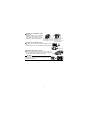
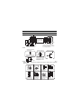
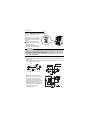
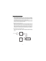
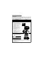
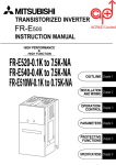
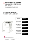
Product Checking and Parts Identification
Unpack the inverter and check the capacity plate on the front cover and the rating
plate on the inverter side face to ensure that the product agrees with your order and
the inverter is intact.
Parts and name plate
Rating plate
Operation panel
Inverter type
Input rating
Output rating
Front cover
Serial number
Capacity plate
Inverter type
Wiring cover
FR-S520E-0.1K
FR-S520E-0.1K
Inverter type
XXXXXX
Serial number
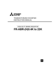
FR - S520E - 0.1 K Voltage class
Symbol
S520E Three-phase 200V class
S540E Three-phase 400V class
S520SE Single-phase 200V class
Symbol Structure, terminal symbol,etc.
Inverter
capacity
"kW"
None
C
S510WE Single-phase 100V class
1
Enclosed type
Totally enclosed structure IP40
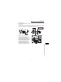
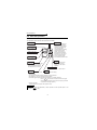
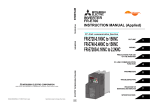
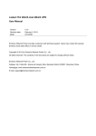
z Removal and reinstallation of the
front cover
Remove the front cover by pulling it
toward you in the direction of arrow.
To reinstall, match the cover to the
FR-S520E-0.1K to 0.75K
inverter front and install it straight.
FR-S520E-1.5K to 3.7K
FR-S520SE-0.1K to 0.75K FR-S520SE-1.5K
FR-S510WE-0.1K to 0.4K FR-S540E-0.4K to 3.7K
FR-S510WE-0.75K
z Removal and reinstallation of the wiring cover
The cover can be removed easily by pulling it toward
you.
To reinstall, fit the cover to the inverter along the guides.
Wiring cover
z RS-485 communication connector
When using the RS-485 connector to wire the cable, you
can cut off the tab of the wiring cover to wire it. (Cutting off
Tab
the tab will provide protective structure IP10.)
CAUTION
The connector above the operation panel is for
manufacturer use. Do not touch it as doing so may
cause an electric shock.
2
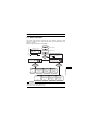
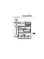
1.
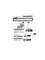
CONNECTION OF PERIPHERAL DEVICES (BASIC
CONFIGURATION)
Power supply
Use within the permissible power supply specifications
of the inverter. (Refer to page 80.)
Moulded case circuit breaker or earth leakage
circuit breaker
The breaker must be selected carefully since an in-rush
current flows in the inverter at power on.
(MCCB)
or (ELB)
Magnetic contactor
Install for your safety. Do not use this magnetic contactor
to start and stop the inverter. Doing so will cause the
inverter life to be shorten. (Refer to page 18.)
Installation of a reactor
A reactor must be used when the power harmonics
measure is taken, power factor is to be improved or the
inverter is installed near a large supply system (500kVA
or more and wiring distance within 10 m).
Make the selection carefully.
AC reactor
(FR-HAL
/FR-BAL)
Inverter
Inverter
(FR-S500E)
Earth (Ground)
Motor
Earth (Ground)
DC reactor
(FR-HEL
/FR-BEL)
The life of the inverter is influenced by ambient
temperature. Check the ambient temperature.
Epecially when mounting the inverter inside an
enclosure, take cautions of the ambient temperature.
(Refer to page 85.)
Wrong wiring might lead to damage of the inverter.
The control signal wires must be kept fully away from the
main circuit to protect them from noise. (Refer to page 7.)
Devices connected to the output
Do not install a power factor correction capacitor, surge
suppressor or capacitor type filter on the output side of the
inverter.
When installing a moulded case circuit breaker on the
output side of the inverter, contact each manufacturer for
selection of the moulded case circuit breaker.
Earth (Ground)
To prevent an electric shock, always earth (ground) the
motor and inverter.
For reduction of induction noise from the power line of
the inverter, it is recommended to wire the earth
(ground) cable by returning it to the earth (ground)
terminal of the inverter.
(For details of noise reduction techniques, refer to the
instruction manual (detailed).)
3
1
CONNECTION OF PERIPHERAL DEVICES (BASIC CONFIGURATION)
(MC)
CONNECTION OF PERIPHERAL DEVICES
(BASIC CONFIGURATION)
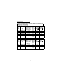
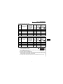
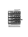
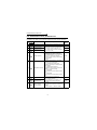
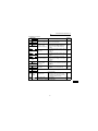
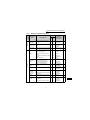
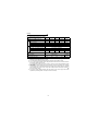
Selection of peripheral devices (selection changes with the power input
specifications of the inverter)
1) Three-phase 200V power input
Motor
Output
(kW)
Applied Inverter
Type
0.1
0.2
0.4
0.75
1.5
2.2
FR-S520E-0.1K(-C)
FR-S520E-0.2K(-C)
FR-S520E-0.4K(-C)
FR-S520E-0.75K(-C)
FR-S520E-1.5K(-C)
FR-S520E-2.2K(-C)
3.7
FR-S520E-3.7K(-C)
Moulded Case
Magnetic
Circuit Breaker
Contactor AC Reactor DC Reactor
(MCCB *1, 4) or
(MC)
FR-HAL-K FR-HEL-K
Earth Leakage
(Refer to FR-BAL-K FR-BEL-K
Circuit Breaker
page 18)
(ELB) (*2, 4)
30AF/5A
S-N10
0.4 (*3)
0.4 (*3)
30AF/5A
S-N10
0.4 (*3)
0.4 (*3)
30AF/5A
S-N10
0.4
0.4
30AF/10A
S-N10
0.75
0.75
30AF/15A
S-N10
1.5
1.5
30AF/20A
S-N10
2.2
2.2
30AF/30A
S-N20,
S-N21
3.7
3.7
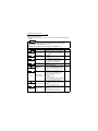
2) Three-phase 400V power input
Motor
Output
(kW)
Applied Inverter
Type
0.4
0.75
1.5
2.2
FR-S540E-0.4K
FR-S540E-0.75K
FR-S540E-1.5K
FR-S540E-2.2K
3.7
FR-S540E-3.7K
Moulded Case
Magnetic
Circuit Breaker
AC Reactor DC Reactor
Contactor
(MCCB *1, 4) or
FR-HAL-K FR-HEL-K
(MC)
Earth Leakage
FR-BAL-K FR-BEL-K
(Refer to
Circuit Breaker
page 18)
(ELB) (*2, 4)
30AF/5A
S-N10
H0.4
H0.4
30AF/5A
S-N10
H0.75
H0.75
30AF/10A
S-N10
H1.5
H1.5
30AF/15A
S-N10
H2.2
H2.2
30AF/20A
S-N20,
S-N21
H3.7
H3.7
4
CONNECTION OF PERIPHERAL DEVICES
(BASIC CONFIGURATION)
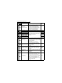
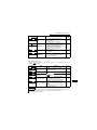
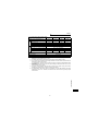
3) Single-phase 200V power input
Motor
Output
(kW)
Applied Inverter
Type
Moulded Case
Magnetic
Circuit Breaker
AC Reactor DC Reactor
Contactor
(MCCB *1, 4) or
(*3)
(*3)
(MC)
Earth Leakage
FR-HAL-K FR-HEL-K
(Refer to
Circuit Breaker
FR-BAL-K FR-BEL-K
page 18)
(ELB) (*2, 4)
0.1
0.2
FR-S520SE-0.1K
FR-S520SE-0.2K
30AF/5A
30AF/10A
0.4
FR-S520SE-0.4K
30AF/10A
0.75 FR-S520SE-0.75K
30AF/15A
1.5
30AF/20A
FR-S520SE-1.5K
S-N10
S-N10
S-N20,
S-N21
S-N20,
S-N21
S-N20,
S-N21
0.4
0.4
0.4
0.4
0.75
0.75
1.5
1.5
2.2
2.2
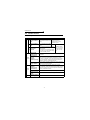
4) Single-phase 100V power input
Motor
Output
(kW)
Applied Inverter
Type
0.1
0.2
FR-S510WE-0.1K
FR-S510WE-0.2K
30AF/10A
30AF/15A
0.4
FR-S510WE-0.4K
30AF/20A
0.75
FR-S510WE-0.75K
30AF/30A
S-N10
S-N10
S-N20,
S-N21
S-N20,
S-N21
*1. • Select the MCCB according to the power supply capacity.
• Install one MCCB per inverter.
0.75
1.5
⎯
⎯
2.2
⎯
3.7
⎯
MCCB
INV
IM
MCCB
INV
IM
*2. For installations in the United States or Canada, the circuit breaker must be inverse
time or instantaneous trip type.
*3. The power factor may be slightly lower.
*4. When the breaker on the inverter primary side trips, check for the wiring fault (short
circuit), damage to internal parts of the inverter, etc. Identify the cause of the trip,
then remove the cause and power on the breaker.
*5. The single-phase 100V power input model is not compatible with the DC reactor.
5
1
CONNECTION OF PERIPHERAL DEVICES (BASIC CONFIGURATION)
Moulded Case
Magnetic
Circuit Breaker
AC Reactor DC Reactor
Contactor
(MCCB *1, 4) or
(*3)
(*5)
(MC)
Earth Leakage
FR-HAL-K FR-HEL-K
(Refer to
Circuit Breaker
FR-BAL-K FR-BEL-K
page 18)
(ELB) (*2, 4)
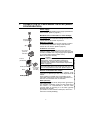
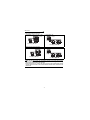
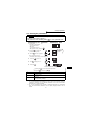
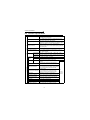
Installation of the inverter
2.
INSTALLATION METHOD
2.1 Installation of the inverter
Enclosure surface mounting
Encasing multiple inverters
Remove the front
cover and wiring
cover to fix to the
surface.
Vertical
When containing two or more
inverters, install them in parallel
as a cooling measure.
Leave enough clearances
as a cooling measure.
z Install the inverter under the following conditions.
Ambient temperature
and humidity
Clearances (front)
1cm
or more
Temperature: -10°C to 50°C
Humidity: 90%RH maximum
Measurement
position
5cm
5cm
Inverter
5cm
Measurement position
Clearances (side)
10cm
or more
1cm
or more
10cm
or more
1cm
Inverter
or more
These clearances are also
necessary for changing the
cooling fan. (The 1.5K or
more is provided with a
cooling fan.)
z Inverter consists of precision mechanical and electronic parts. Never install or
handle it in any of the following conditions as doing so could cause an operation
fault or failure.
Direct sunlight
Vertical mounting
(when mounting
inside an enclosure)
Vibration
(5.9m/s2 or more)
High temperature,
high humidity
Horizontal placement
Transportation
by holding front
cover or dial
Oil mist, flammable
gas, corrosive gas,
fluff, dust, etc.
Mounting to
combustible material
6
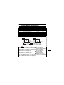
Terminal connection diagram
3.
SPECIFICATIONS OF WIRING AND TERMINALS
3.1 Terminal connection diagram
z Three-phase 200V power input
z Three-phase 400V power input
Inverter
Three-phase AC
power supply
R/L1
S/L2
T/L3
External transistor common
24VDC power supply
Contact input common (source)
PC
DC reactor
(FR-HEL/BEL: Option)
Take care not to short
terminals PC-SD.
Forward rotation start
Control input
Reverse rotation start
signals
High speed
(No voltage Multi-speed Middle speed
selection
input allowed)
Low speed
Contact input common
Motor
IM
Earth
(Ground)
U
V
W
P1
P/+
STF
STR
RH
RM
RL
SD
Jumper: Remove this
jumper when DC reactor
is connected.
*1 N/*6
*6
*6
*6
*2 PR
*7 A
*7 B
*7 C
R
Alarm output
*7 RUN Running
SE Open
Frequency setting signals (Analog)
Frequency setting
potentiometer
1/2W1kW *5
collector
output
common
10 (+5V)
3
2
2 0 to 5VDC Selected
0 to 10VDC
1
Current input(-)
4 to 20mADC(+)
5
(Common)
FM
Calibration
resistor *3
4 (4 to 20mADC)
SINK
When using the current input as
the frequency setting signal, set
"4" in any of Pr. 60 to Pr. 63 (input
terminal function selection), assign
AU (current input selection) to any
of terminals RH, RM, RL and STR
and turn on the AU signal.
*4
Brake resister
Operation status
output
Open collector
outputs
Indicator
1mA full-scale
Analog meter
(Digital indicator)
(+)
(-)
SD
SOURCE
RS-485
Connector
Earth (Ground)
Main circuit terminal
Control circuit terminal
REMARKS
*1.
*2.
*3.
*4.
*5.
*6.
*7.
The N/- terminal is not provided for the FR-S520E-0.1K to 0.75K.
The PR terminal is provided for the FR-S520E-0.4K to 3.7K.
Not needed when the setting dial is used for calibration.
Used when calibration must be made near the frequency meter for such a reason as a remote frequency meter.
However, the frequency meter needle may not deflect to full-scale if the calibration resistor is connected.
In this case, use this resistor and setting dial together.
You can switch the position of sink and source logic. (Refer to page 16.)
When the setting potentiometer is used frequently, use a 2W1kΩ potentiometer.
The terminal functions change with input terminal function selection (Pr. 60 to Pr. 63). (Refer to page 57.)
(RES, RL, RM, RH, RT, AU, STOP, MRS, OH, REX, JOG, X14, X16, (STR) signal selection)
The terminal function changes according to the setting of output terminal function selection (Pr. 64, Pr. 65).
(Refer to page 57.) (RUN, SU, OL, FU, RY, Y12, Y13, FDN, FUP, RL, Y93, Y95, LF, ABC signal selection)
7
3
SPECIFICATIONS OF WIRING AND TERMINALS
MCCB MC
Main circuit
CAUTION
To prevent a malfunction due to noise, keep the signal cables more than 10cm away
from the power cables.
z Single-phase 200V power input
z Single-phase 100V power input
MCCB
MC
Power
supply
Motor
R/L1
S/L2
U
V
W
IM
Earth (Ground)
REMARKS
• To ensure safety, connect the power input to the inverter via a magnetic contactor and earth leakage
circuit breaker or moulded case circuit breaker, and use the magnetic contactor to switch power on-off.
• The output is three-phase 200V.
3.2 Main circuit
3.2.1
Explanation of main circuit terminals
Terminal
Symbol
R/L1, S/L2,
T/L3 (*1)
U, V, W
Terminal Name
Description
AC power input Connect to the commercial power supply.
Inverter output Connect a three-phase squirrel-cage motor.
Connect the optional brake resistor (MRS/MYS type, FR-
P/+, PR (*2)
Brake resistor
ABR) (The brake resistor can be connected to the FRconnection
S520E-0.4K to 3.7K only.)
P/+, N/−
Brake unit
connection
P/+, P1
DC reactor
connection
Connect the brake unit (BU), power regeneration
common converter (FR-CV) or high power factor
converter (FR-HC). (The N/- terminal is not provided for
the FR-S520E-0.1K to 0.75K.)
Remove the jumper across terminals P - P1 and connect
the optional DC reactor (FR-HEL(-H)/FR-BEL(-H)).
(The single-phase 100V power input model cannot be
connected.)
For earthing (grounding) the inverter chassis. Must be
earthed (grounded).
*1. When using single-phase power input, terminals are R/L1 and S/L2.
*2. The PR terminal is provided for the FR-S520E-0.4K to 3.7K.
Earth (ground)
8
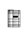
Main circuit
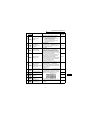
3.2.2
Terminal block layout
1) Three-phase 200V power input
• FR-S520E-0.1K, 0.2K (-C)
• FR-S520E-1.5K, 2.2K, 3.7K (-C)
Jumper
R/L1
S/L2
T/L3
U
Jumper
P1
P/+
N/-
P/+
V
W
PR
P1
R/L1
S/L2
T/L3
U
V
W
IM
Motor
Power supply
IM
Power supply
Motor
• FR-S520E-0.4K, 0.75K (-C)
Jumper
R/L1
S/L2
T/L3
PR
P1
P/+
U
V
W
IM
3
2) Three-phase 400V power input
• FR-S540E-0.4K, 0.75K, 1.5K, 2.2K, 3.7K (-C)
Jumper
N/-
P/+
P1
R/L1 S/L2
T/L3
U
V
IM
Power supply Motor
9
W
SPECIFICATIONS OF WIRING AND TERMINALS
Power supply
Motor
Main circuit
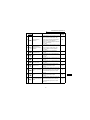
3) Single-phase 200V power input
• FR-S520SE-0.1K, 0.2K, 0.4K, 0.75K
• FR-S520SE-1.5K
Jumper
R/L1
S/L2
N/-
P1
P/+
U
V
W
Jumper
N/-
P/+
P1
R/L1 S/L2
U
V
W
IM
Power supply
IM
Motor
Motor
Power supply
4) Single-phase 100V power input
• FR-S510WE-0.1K, 0.2K, 0.4K
N/-
R/L1
S/L2
U
• FR-S510WE-0.75K
P/+
V
N/-
P/+
W
R/L1
S/L2
U
V
W
IM
Power supply
IM
Motor
Power supply
Motor
CAUTION
•Make sure the power cables are connected to the R/L1, S/L2, T/L3 of the inverter.
Never connect the power cable to the U, V, W of the inverter. Doing so will damage
the inverter. (Phase need not be matched)
•Connect the motor to U, V, W. At this time, turning on the forward rotation switch
(signal) rotates the motor in the counterclockwise direction when viewed from the
motor shaft.
10
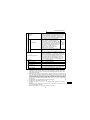
Main circuit
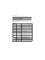
3.2.3
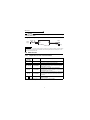
Cables, wiring length, and crimping terminals
The following table indicates a selection example for the wiring length of 20m.
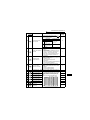
1) Three-phase 200V power input
Cable Size
Ter- TightCrimping
PVC cable
HIV cable
minal ening
AWG
Applied Inverter
Terminal
Screw Torque
(mm2)
(mm2)
size N⋅m R, S, T U, V, W R, S, T U, V, W R, S, T U, V, W R, S, T U, V, W
FR-S520E-0.1K
M3.5
to 0.75K (-C)
FR-S520EM4
1.5K, 2.2K (-C)
FR-S520E-3.7K
M4
(-C)
1.2
2-3.5
2-3.5
2
2
14
14
2.5
2.5
1.5
2-4
2-4
2
2
14
14
2.5
2.5
1.5
5.5-4
5.5-4
3.5
3.5
12
12
4
2.5
2) Three-phase 400V power input
Cable Size
Ter- TightCrimping
PVC cable
HIV cable
minal ening
AWG
Applied Inverter
Terminal
2
Screw Torque
(mm2)
(mm )
size N⋅m R, S, T U, V, W R, S, T U, V, W R, S, T U, V, W R, S, T U, V, W
FR-S540E-0.4K
M4
1.5
2-4
2-4
2
2
14
14
2.5
2.5
to 3.7K
3) Single-phase 200V power input
4) Single-phase 100V power input
Cable Size
Termi- TightCrimping
PVC cable
HIV cable
nal
ening
Applied Inverter
AWG
Terminal
Screw Torque
(mm2)
(mm2)
size
N⋅m R, S U, V, W R, S U, V, W R, S U, V, W R, S U, V, W
FR-S510WE-0.1K
M3.5
1.2 2-3.5 2-3.5
2
2
14
14
2.5
2.5
to 0.4K
M4
1.5 5.5-4 2-4
3.5
2
12
14
4
2.5
FR-S510WE-0.75K
z Wiring length
100m maximum. (50m maximum for the FR-S540E-0.4K.)
CAUTION
•When the wiring length of the 0.1K and 0.2K of the three-phase 200V, singlephase 200V, and single-phase 100V class and the 0.4K and 0.75K of the threephase 400V class is 30m or more, set the carrier frequency to 1kHz.
•When automatic torque boost is selected in Pr. 98 "automatic torque boost
selection (motor capacity)", the wiring length should be 30m maximum. (Refer
to page 60.)
11
3
SPECIFICATIONS OF WIRING AND TERMINALS
Cable
Termi- TightCrimping
PVC Cable
HIV cable
nal
ening
AWG
Applied Inverter
Terminal
2
Screw Torque
(mm2)
(mm )
size
N⋅m R, S U, V, W R, S U, V, W R, S U, V, W R, S U, V, W
FR-S520SE-0.1K
M3.5
1.2 2-3.5 2-3.5
2
2
14
14
2.5
2.5
to 0.75K
M4
1.5
2-4
2-4
2
2
14
14
2.5
2.5
FR-S520SE-1.5K
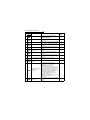
Control circuit
3.3 Control circuit
3.3.1
Explanation of control circuit terminals
Input signals
Contact input
Symbol
Terminal Name
STF
Forward rotation
start
STR
Reverse rotation
start
RH
Multi-speed
RM
selection
RL
Contact input
common (sink)
(initial setting)
Definition
When the STF and STR
Turn on the STF signal to start
signals are turned on
forward rotation and turn it off
simultaneously, the stop
to stop.
command is given.
Turn on the STR signal to start
reverse rotation and turn it off
The terminal
to stop.
functions change
Turn on the RH, RM and RL signals in
with input terminal
appropriate combinations to select
function selection
multiple speeds.
(Pr. 60 to Pr. 63).
The priorities of the speed commands
(*3)
are in order of jog, multi-speed setting
(RH, RM, RL, REX) and AU.
Common terminal for contact input terminal (sink logic) and
terminal FM.
When connecting the transistor output (open collector
External
output), such as a programmable controller (PLC), when
SD
source logic is selected, connect the external power supply
transistor
(*1, 6)
common (source) common for transistor output to this terminal to prevent a
24VDC power
supply common
PC
(*1)
10
External
transistor
common (sink)
(initial setting)
malfunction caused by undesirable currents.
Common output terminal for 24VDC 0.1A power supply (PC
terminal)
Isolated from terminals 5 and SE.
When connecting the transistor output (open collector
output), such as a programmable controller (PLC), when sink
logic is selected, connect the external power supply common
for transistor output to this terminal to prevent a malfunction
caused by undesirable currents.
Contact input
Common terminal for contact input terminal (source logic)
common (source)
24VDC power
Can be used as 24VDC 0.1A power supply.
supply
Frequency setting
5VDC, Permissible load current 10mA.
power supply
12
Control circuit
Terminal Name
Definition
Inputting 0 to 5VDC (or 0 to 10V) provides the maximum output
Frequency setting frequency at 5V (10V) and makes input and output proportional.
2
Switch between 5V and 10V using Pr. 73 "0-5V, 0-10V selection".
(voltage signal)
Input resistance 10kΩ. Maximum permissible input voltage 20V
Input 4 to 20mADC. It is factory set at 0Hz for 4mA and at
60Hz for 20mA.
Maximum permissible input current 30mA. Input resistance
Frequency setting approximately 250Ω.
4
Turn ON signal AU for current input.
(current signal)
Turning the AU signal on makes voltage input invalid. Use
any of Pr. 60 to Pr. 63 (input terminal function selection) to set
the AU signal.
Frequency setting Frequency setting signal (terminal 2, 4) common terminal.
5
(*6)
input common
1 changeover contact output indicates
that the inverter protective function has
A
activated and the output stopped.
B
Alarm output
230VAC 0.3A, 30VDC 0.3A. Alarm:
The function of the
discontinuity across B-C (continuity
C
across A-C), Normal: continuity across B- terminals changes
according to the
C (discontinuity across A-C).(*5)
output terminal
Switched low when the inverter output
function selection
frequency is equal to or higher than the
(Pr. 64, Pr. 65).
starting frequency (factory set to 0.5Hz
(*4)
Inverter
variable). Switched high during stop or DC
RUN
running
injection brake operation. (*2) Permissible
load 24VDC 0.1A (a voltage drop is 3.4V
maximum when the signal is on)
SE
Open collector
common
Common terminal for inverter running terminal RUN. (*6)
FM For meter
The output signal across terminals FM-SD is factory set to
about 1mA at 60Hz and is proportional to the corresponding
output frequency. Since output voltage is pulse waveform, a
digital meter can be connected.
Frequency permissible load current 1mA
Pulse specification 1440 pulses/s at 60Hz
RS-485
connector
Using the parameter unit connection cable (FR-CB201 to
205), the parameter unit (FR-PU04) can be connected.
Communication operation can be performed using RS-485.
For details of RS-485 communication, refer to the separately
available instruction manual (detailed).
——
*1. Do not connect terminals SD and PC each other or to the earth (ground).
For sink logic (factory setting), terminal SD acts as the common terminal of contact input. For
source logic, terminal PC acts as the common terminal of contact input. (Refer to the separately
available instruction manual (detailed) for switching method.)
*2. Low indicates that the open collector output transistor is on (conducts). High indicates that the
transistor is off (does not conduct).
*3. RL, RM, RH, RT, AU, STOP, MRS, OH, REX, JOG, RES, X14, X16, (STR) signal selection
(Refer to page 57.)
*4. RUN, SU, OL, FU, RY, Y12, Y13, FDN, FUP, RL, Y93, Y95, LF, ABC signal selection (Refer to
page 57.)
*5. To be compliant with the European Directive (Low Voltage Directive), the operating capacity of
relay outputs (A, B, C) should be 30VDC 0.3A.
*6. Terminals SD, SE and 5 are isolated from each other. Do not earth (ground).
13
3
SPECIFICATIONS OF WIRING AND TERMINALS
Communication
Output signals
Indicator
Open collector
Input signals
Frequency setting
Symbol
Control circuit
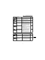
3.3.2
Arrangement and wiring of control circuit terminals
PC SE RUN 10
2
5
4
SD SD STF STR RL RM RH FM
Control circuit terminal block
A
B
C
Loosen the terminal screw and insert the cable into the
Cable stripping size
terminal.
Screw size: M3 (A, B, C terminals),
M2 (other than the above)
Tightening torque: 0.5N•m to 0.6N•m (A, B, C termiWire the stripped cable after
nals)
0.22N•m to 0.25N•m (other than the twisting it to prevent it from
becoming loose.
above)
In addition, do not solder it. *
CAUTION
Undertightening can cause cable
disconnection or malfunction. Overtightening
can cause a short circuit or malfunction due
to damage to the screw or unit.
0.3mm2
0.75mm2
ABC
terminals
Other than
the above
6mm
5mm
Cable size:
to
Screwdriver: Small flat-blade screwdriver
Tip thickness: 0.4mm
Tip width: 2.5mm
*Information on bar terminals
Introduced products (as of September, 2006): Phoenix Contact Co.,Ltd.
Terminal Screw Size
M3 (A, B, C terminal)
M2 (Other than the above)
Bar Terminal Model
(With Insulation Sleeve)
Bar Terminal Model
(Without Insulation Sleeve)
Wire Size (mm 2)
AI 0,5-6 WH
A 0,5-6
0.3 to 0.5
AI 0,75-6 GY
A 0,75-6
0.5 to 0.75
AI 0,5-6 WH
A 0,5-6
0.3 to 0.5
Bar terminal crimping tool: CRIMPFOX ZA3 (Phoenix Contact Co., Ltd.)
CAUTION
When using the bar terminal (without insulation sleeve), use care so that the
twisted wires do not come out.
14
Control circuit
3.3.3
Connection to RS-485 connector
(1) When connecting the parameter unit
Use the optional FR-CB2
. When the parameter unit (FR-PU04) is used,
STOP
operation from the operation panel is not accepted. ( RESET
is valid)
(2) RS-485 communication
Using the RS-485 connector, you can perform communication operation from a
personal computer etc. By connecting the RS-485 connector to computers such
as personal computer and FA with a communication cable, you can run/monitor
the inverter and read/write parameter values using a user program. For further
details, refer to the instruction manual (detailed).
· Conforming standard: EIA-485 (RS-485)
· Transmission format: Multi-drop link
· Communication speed: Maximum 19200 bps
· Overall extension: 500m
CAUTION
Do not plug the connector to a computer LAN board, fax modem socket, telephone modular connector etc. The inverter and machine could be damaged
due to differences in electrical specifications.
SPECIFICATIONS OF WIRING AND TERMINALS
3
15
Control circuit
3.3.4
Changing the control logic
The input signals are set to sink
logic.
To change the control logic, the
jumper connector under the setting
dial must be moved to the other
position.
Change the jumper connector
position using tweezers, a pair of
long-nose pliers etc.
Change the jumper connector
position before switching power on.
CAUTION
•Make sure that the front cover is installed securely.
•The front cover is fitted with the capacity plate and the inverter unit with the
rating plate. Since these plates have the same serial numbers, always replace
the removed cover onto the original inverter.
•The sink-source logic change-over jumper connector must be fitted in only
one of those positions. If it is fitted in both positions at the same time, the
inverter may be damaged.
1) Sink logic type
• In this logic, a signal switches on when a current flows from the corresponding signal
input terminal.
Terminal SD is common to the contact input signals. Terminal SE is common to the
open collector output signals.
Sink logic
DC input (sink type)
<Example: QX40>
Inverter
Current
STF
STR
R
Sink
connector
RUN
TB1
R
R
R
TB17
SE
SD
24VDC
Current flow
• Use terminal PC as a common
terminal, and perform wiring as
shown on the right. (Do not connect
terminal SD of the inverter with
terminal 0V of the external power
supply. When using terminals PC-SD
as a 24VDC power supply, do not
install a power supply in parallel in the
outside of the inverter. Doing so may
cause a malfunction due to
undesirable current.)
Inverter
QY40P type transistor
output unit
TB1 STF
24VDC
(SD)
TB2 STR
Constant
voltage
circuit
TB17
PC
TB18
24VDC SD
Current flow
16
Control circuit
2) Source logic type
• In this logic, a signal switches on when a current flows into the corresponding signal
input terminal.
Terminal PC is common to the contact input signals. For the open collector output
signals, terminal SE is a positive external power supply terminal.
Source logic
DC input (source type)
<Example: QX80>
Inverter
PC
Current
STF
R
Source
connector
TB1
RUN
R
R
STR
R
TB18
SE
24VDC
Current flow
• Use terminal SD as a common
Inverter
QY80 type transistor
output unit
terminal, and perform wiring as
shown on the right. (Do not connect
terminal PC of the inverter with
terminal +24V of the external power
supply. When using terminals PC-SD
as a 24VDC power supply, do not
install an external power supply in
parallel with the inverter. Doing so
may cause a malfunction in the
inverter due to undesirable currents.)
PC
Fuse
STF
TB2
STR
TB17
TB18
24VDC
Constant
voltage
circuit
TB1
24VDC
(SD)
SD
3
SPECIFICATIONS OF WIRING AND TERMINALS
Current flow
17
Control circuit
3.3.5
Power-off and magnetic contactor (MC)
(1) Inverter input side magnetic contactor (MC)
On the inverter's input side, it is recommended to provide an MC for the following
purposes. (Refer to page 4 for selection)
1) To release the inverter from the power supply when the inverter protective function
is activated or the drive becomes faulty (e.g. emergency stop operation)
When cycle operation or heavy-duty operation is performed with an optional brake
resistor connected, overheat and burnout of the electrical-discharge resistor can be
prevented if a regenerative brake transistor is damaged due to insufficient heat
capacity of the electrical-discharge resistor and excess regenerative brake duty.
2) To prevent any accident due to an automatic restart at restoration of power after an
inverter stop made by a power failure
3) To rest the inverter for an extended period of time
The control power supply for inverter is always running and consumes a little power.
When stopping the inverter for an extended period of time, powering off the inverter
will save power slightly.
4) To separate the inverter from the power supply to ensure safe maintenance and
inspection work
The inverter's input side MC is used for the above purpose, select class JEM1038AC3 for the inverter input side current when making an emergency stop during
normal operation.
REMARKS
The MC may be switched on/off to start/stop the inverter. However, since repeated inrush
currents at power on will shorten the life of the converter circuit (switching life is about 100,000
times), frequent starts and stops must be avoided. Turn on/off the inverter start controlling
terminals (STF, STR) to run/stop the inverter.
As shown on the right,
always use the start signal
Power
(ON or OFF across
terminals STF or STR-SD) supply
to make a start or stop.
*1. When the power supply
is 400V class, install a
step-down transformer.
MCCB
MC
R/L1
S/L2
T/L3
U
V
W
T (*1)
Inverter
Operation ready
OFF ON
MC
To
motor
A
B
C
MC
RA
Start/Stop
STF(STR)
SD
Operation
MC
OFF
RA
RA
Inverter Start/Stop Circuit Example
(2) Handling of output side magnetic contactor
In principle, do not provide a magnetic contactor between the inverter and motor and
switch it from off to on during operation. If it is switched on during inverter operation, a
large inrush current may flow, stopping the inverter due to overcurrent shut-off. When
an MC is provided for switching to the commercial power supply, for example, switch it
on/off after the inverter and motor have stopped.
18
Failsafe of the system which uses the inverter
3.4 Failsafe of the system which uses the inverter
When a fault occurs, the inverter trips to output an alarm. However, an alarm output
signal may not be output at an inverter alarm occurrence when the detection circuit or
output circuit fails, etc. Although Mitsubishi assures best quality products, provide an
interlock which uses inverter status output signals to prevent accidents such as
damage to machine when the inverter fails for some reason and at the same time
consider the system configuration where failsafe from outside the inverter, without
using the inverter, is enabled even if the inverter fails.
(1) Interlock method which uses the inverter status output signals
By combining the inverter status output signals to provide an interlock as shown
below, an inverter alarm can be detected.
Interlock Method
Check Method
1)
Inverter protective
function operation
Operation check of an
alarm contact
Circuit error detection by
negative logic
Used Signals
Refer to Page
Alarm output signal
(ABC signal)
Refer to the chapter
2 of the Instruction
Manual (detailed)).
2)
Inverter running
status
Operation ready signal
check
Operation ready signal
(RY signal)
Refer to the chapter
2 of the Instruction
Manual (detailed)).
3)
Inverter running
status
Logic check of the start
signal and running
signal
Start signal
(STF signal, STR signal)
Running signal
(RUN signal)
Refer to the chapter
2 of the Instruction
Manual (detailed)).
4)
Inverter running
status
Logic check of the start
signal and output
current
Start signal
(STF signal, STR signal)
Output current detection
signal
(Y12 signal)
Refer to the chapter
2 of the Instruction
Manual (detailed)).
3
SPECIFICATIONS OF WIRING AND TERMINALS
No
19
Failsafe of the system which uses the inverter
(2) Backup method outside the inverter
Even if the interlock is provided by the inverter status signal, enough failsafe is
not ensured depending on the failure status of the inverter itself. For example,
even if the interlock is provided using the inverter alarm output signal, start signal
and RUN signal output, there is a case where an alarm output signal is not output
and RUN signal is kept output even if an inverter alarm occurs.
Provide a speed detector to detect the motor speed and current detector to detect
the motor current and consider the backup system such as checking up as below
according to the level of importance of the system.
1) Start signal and actual operation check
Check the motor running and motor current while the start signal is input to the
inverter by comparing the start signal to the inverter and detected speed of the
speed detector or detected current of the current detector. Note that the motor
current runs as the motor is running for the period until the motor stops since the
inverter starts decelerating even if the start signal turns off. For the logic check,
configure a sequence considering the inverter deceleration time. In addition, it is
recommended to check the three-phase current when using the current detector.
2) Command speed and actual operation check
Check if there is no gap between the actual speed and commanded speed by
comparing the inverter speed command and detected speed of the speed
detector.
Controller
System failure
Sensor
(speed, temperature,
air volume, etc.)
Inverter
To the alarm detection sensor
20
Step of operation
4.
DRIVE THE MOTOR
4.1 Step of operation
The inverter needs frequency command and start command. Turning the start
command on start the motor rotating and the motor speed is determined by the
frequency command.
Refer to the flow chart below to perform setting.
Frequency (Hz)
Step
Step of
of operation
op
operation
Frequency command
Installation/mounting
{Refer to page 6}
Wiring of the power
supply and motor
{Refer to page 9}
Inverter output
frequency
Time
(S)
ON
Start
command
System examination
Start command using the RS-485
connector of the inverter
(Communication)
Refer to
Instruction Manual
(detailed)
How
to give a start
command?
Start command with
RUN
-
Connect a switch, relay, etc.
to the control circuit
terminal block of the inverter
to give a start command. (External)
+
on the operation panel (PU)
How to
give a frequency
command?
How to
give a frequency
command?
Set from the
operation
panel.
(PU)
Change frequency
with ON/OFF switches
connected to terminals
(multi-speed setting)
(External)
{Refer to page 24} {Refer to page 26}
Perform frequency
setting by a voltage
output device
(Connection across
terminals 2-5)
(External)
Perform frequency
setting by a current
output device
(Connection across
terminals 4-5)
(External)
{Refer to page 28}
{Refer to page 29}
(PU)
(External)
Perform frequency
setting by a voltage
output device
(Connection across
terminals 2-5)
(External)
{Refer to page 31}
{Refer to page 33}
{Refer to page 35}
Set from the
operation panel
Change of frequency
with ON/OFF switches
connected to terminals
(multi-speed setting)
CAUTION
Perform frequency
setting by a current
output device
(Connection across
Terminals 4-5)
(External)
{Refer to page 37}
Check the following items before powering on the inverter.
•Check that the inverter is installed correctly in a correct place. (Refer to page 6)
•Check that wiring is correct. (Refer to page 7)
•Check that no load is connected to the motor.
21
DRIVE THE MOTOR
4
Run and operation
4.2 Run and operation
4.2.1
Parts of the operation panel
The operation panel cannot be removed from the inverter.
PU/EXT Key
RUN indication
Turns on/flickers* to indicate operation.
PU indication **
Lit to indicate PU
operation mode.
RUN
PU
PU
EXT
EXT
RUN
3-digit monitor LED
Shows the frequency,
parameter number, etc.
STOP
RESET
MODE
EXT indication **
SET
Used to switch between the
PU and external operation
mode. When using external
operation mode (operation
using the separately
connected frequency setting
potentiometer and start
signal), press this key to
light up the EXT indication.
(Change the Pr. 79 value to
use the combined mode.)
PU: PU operation mode
EXT: External operation mode
Lit to indicate external
operation mode.
RUN Key
Setting dial
Used to give the forward
rotation run command.
Use Pr. 17 to set reverse
operation.
(Setting dial: Mistubishi inverter's dial)
Used to change the frequency
setting and parameter values.
This dial cannot be removed.
STOP/RESET Key
reset an alarm.
MODE Key
SET Key
Used to change the setting mode.
Used to define each setting.
* RUN indication
On: Indicates that forward rotation operation is being performed.
Slow flickering (1.4s cycle): Indicates reverse rotation
Fast flickering (0.2s cycle): Indicates that operation is not being performed
but the RUN was pressed or the start command was given.
When the start command is given and the frequency command
is less than the strating frequency.
** PU/EXT indication
Flickers slowly in the computer link operation mode.
REMARKS
•When the parameter unit (FR-PU04) is used, operation from the operation panel is not
accepted. (
STOP
RESET
is valid)
22
Run and operation
4.2.2
Basic operation
The following explains the outline of operation. (factory setting)
At powering on
Monitor/frequency setting
Return
MODE
Press
MODE
key.
[Operation panel is used for operation]
Frequency setting has
PU
SET
been written and
EXT
completed!!
Press
Turn the
Press
and frequency flickers.
PU/EXT setting dial
SET key
Press RUN to start.
key.
to match
STOP
frequency.
Press
to stop.
RESET
Parameter setting
[Parameter setting change]
PU
EXT
Press
MODE
key.
SET
Turn the
setting dial
to change
value.
Alarm history
Press SET
key to
complete
setting.
Press SET key to
show present setting.
After setting is completed,
press the MODE once to show
alarm history, or twice to
show frequency setting screen.
[Operation for displaying alarm history]
Four past alarms can be displayed with the setting dial
(The latest alarm is ended by ".".)
When no alarm exists,
is displayed.
MODE
Press MODE key.
23
4
.
DRIVE THE MOTOR
MODE
SET
Press
Turn the setting
PU/EXT dial to match
key.
frequency.
Operation by the start command from the operation panel
(PU operation mode)
4.3 Operation by the start command from the
operation panel (PU operation mode)
4.3.1
Setting the frequency to perform operation
(example: performing operation at 30Hz)
POINT
•Set "0" (setting dial frequency setting mode) in Pr. 53 "frequency setting
operation selection".
Display
Operation
RUN
1. Screen at power-on
PU
The monitor display appears.
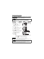
2.
3.
4.
EXT
RUN
PU
Press the EXT to choose PU
operation mode.
PU
EXT
Turn the
to show
the frequency you want to set.
Flickers for about 5s.
PU
EXT
Flickers for about 5s.
While the value is flickering,
press the SET to set the
frequency.
SET
Flicker...Frequency setting complete!!
If you do not press the SET ,
the value flickers for about 5s and
the display then returns to 0.0
(monitor display). At this time,
return to "step 3" and set the
frequency again.
5.
PU indication is lit.
After the value flickered for about
3s, the display returns to 0.0
(monitor display).
3s later
RUN
STOP
RESET
STOP
RESET
to stop.
PU
EXT
Press the RUN to start operation.
To
6. change the set frequency, perform
the operation in above steps 3 and 4.
(Starting from the previously set frequency.)
7. Press the
RUN
RUN
PU
EXT
Operation cannot be performed at the set frequency ... Why?
Did you carry out step 4 within 5s after step 3?
(Did you press the
SET
within 5s after turning the setting dial?)
Setting of higher than 60Hz cannot be made ... Why?
Check to see if the Pr. 1 "maximum frequency" setting is 60Hz.
The frequency does not change by turning the setting dial ... Why?
Check to see if the operation mode selected is external operation mode.
REMARKS
Pressing the setting dial shows the set frequency.
•The setting dial can also be used like a potentiometer to perform operation. (Refer to page 25.)
24
Operation by the start command from the operation panel
(PU operation mode)
4.3.2
Using the setting dial like a potentiometer to perform
operation
POINT
•Set "1" (extended function parameter valid) in Pr. 30 "extended function
display selection".
•Set "1" (setting dial potentiometer mode) in Pr. 53 "frequency setting
operation selection".
Operation example Changing the frequency from 0Hz to 60Hz during operation
Operation
1.
Display
Mode/monitor check.
Choose monitor/frequency monitor.
The inverter must be in
PU operation mode. (Press the
Pr. 30 must be set to "1".
Pr. 53 must be set to "1".
2.
3.
Press the RUN
the inverter.
PU
EXT
RUN
(
MODE
PU
EXT
.)
RUN
to start
PU
RUN
EXT
Turn the
clockwise
until "60.0" appears.
The flickering frequency is
the set frequency.
You need not press the
)
SET
Flickers for 3s.
.
4
25
DRIVE THE MOTOR
REMARKS
•If flickering "60.0" turns to "0.0", the Pr. 53 "frequency setting operation selection" setting may
not be "1".
•Independently of whether the inverter is running or at a stop, the frequency can be set by
merely turning the dial.
Operation by the start command from the operation panel
(PU operation mode)
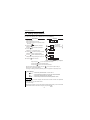
4.3.3
Use switchs to give a start command and a frequency
command (multi-speed setting)
POINT
•Use RUN to give a start command.
•Pr. 79 "operation mode selection" must be set to "4" (external/PU combined
operation mode 2)
•The factory setting of the terminal RH, RM, RL, are 60Hz, 30Hz, and 10Hz.
(Refer to page 47 to change frequency using Pr. 4, Pr. 5 and Pr. 6.)
•Operation at 15-speed can be performed by turning on two (or three)
terminals simultaneously. (Refer to
Instruction Manual (detailed).)
Inverter
Three-phase
AC power supply
High speed
Middle speed
Low speed
R
S
T
U
V
W
RH
RM
RL
Operation
SD
panel
㧙
RUN
2.
3.
Turn
until
,
STOP
RESET
RUN
Screen at powering on
The monitor display appears.
Press MODE to choose the
parameter setting mode.
㧗
Display
Operation
1.
Motor
PU
EXT
MODE
The parameter
number read
previously appears.
(Pr. 79)
appears.
4.
Press SET to read the currently
set value.
"
5.
Turn
to change it to the
setting value of "
6.
SET
" (factory setting) appears.
Press
SET
to set.
".
SET
Flicker ・・・ Parameter setting complete!!
26
Operation by the start command from the operation panel
(PU operation mode)
7.
Mode/monitor check
Press
MODE
RUN
twice to choose the
MODE
PU
EXT
monitor/frequency monitor.
9.
10.
11.
RUN
Press the start switch RUN .
RUN flickers.
When the frequency command is
not given, it flickers.
Flickering
RUN
PU
EXT
Low speed
Turn on the low speed switch (RL).
The output frequency
increases to 10Hz according
to Pr. 7 "acceleration time".
Turn off the low speed switch (RL).
The output frequency
decreases to 0Hz according
to Pr. 8 "deceleration time".
STOP
Turn off the start switch RESET .
RUN turns off.
RUN
PU
EXT
Low speed
RUN
Flickering
PU
EXT
RUN
STOP
RESET
PU
EXT
60Hz for the RH, 30Hz for the RM, 10Hz for the RL are not output when they are
turned on ... Why?
Check for the setting of Pr. 4, Pr. 5, and Pr. 6 once again.
Check for the setting of Pr. 1 "maximum frequency" and Pr. 2 "minimum
frequency" once again. (Refer to page 47.)
Check that Pr. 60 "RL terminal function selection" = "0", Pr. 61 "RM terminal
function selection" = "2", Pr. 62 "RH terminal function selection" and Pr. 59
"remote function selection" = "0". (all are factory setting)
[RUN] lamp is not lit ... Why?
Check that wiring is correct. Check the wiring once again.
Check for the Pr. 79 setting once again. (Pr. 79 must be set to "4".)
(Refer to page 47)
Change the frequency of the terminal RL, RM, and RH. ...How?
Refer to page 47 to change the running frequency at each terminal in Pr. 4
"multi-speed setting (high speed)", Pr. 5 "multi-speed setting (middle speed)",
and Pr. 6 "multi-speed setting (low speed)".
27
4
DRIVE THE MOTOR
8.
Operation by the start command from the operation panel
(PU operation mode)
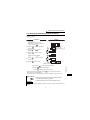
4.3.4
Perform frequency setting by analog (voltage input)
POINT
[Connection diagram]
RUN
•Use
to give a start
command.
•Pr. 79 "operation mode selection"
must be set to "4" (external/PU
combined operation mode 2)
Inverter
U
V
W
Three-phase
AC power supply
R/L1
S/L2
T/L3
Frequency setting
potentiometer
10 Operation
panel
2
5
㧙
㧗
RUN
RUN
PU
EXT
Change the Pr. 79 setting to " ".
(Refer to page 26 for change of the setting.)
3.
Mode/monitor check
Press MODE twice to choose the
monitor/frequency monitor.
5.
6.
7.
STOP
RESET
Screen at powering on
The monitor display appears.
2.
4.
,
Display
Operation
1.
Motor
Flicker ・・・ Parameter setting complete
RUN
MODE
PU
EXT
Start
Press the start switch RUN .
Operation status indication of RUN flickers.
Acceleration → constant speed
Turn the potentiometer (frequency setting
potentiometer) clockwise slowly to full.
The frequency value on the indication
increases according to Pr. 7 "acceleration
time" until 60.00Hz is displayed.
Deceleration
Turn the potentiometer (frequency
setting potentiometer) counterclockwise
slowly to full.
The frequency value on the indication
decreases according to Pr. 8 "deceleration
time" until 0.00Hz is displayed and
operation status indication of RUN flickers.
The motor stops.
Stop
STOP
Press RESET .
Operation status indication of RUN turns off.
RUN
RUN
Flickering
PU
EXT
RUN
PU
EXT
RUN
Flickering
PU
EXT
RUN
STOP
RESET
PU
EXT
Change the frequency (60Hz) of the maximum value of potentiometer (at 5V)
Adjust the frequency in Pr. 38 "frequency setting voltage gain frequency".
(Refer to page 43)
Change the frequency (0Hz) of the minimum value of potentiometer (at 0V)
Adjust the frequency in calibration parameter C2 "frequency setting voltage
bias frequency". (Refer to
Instruction Manual (detailed).)
28
Operation by the start command from the operation panel
(PU operation mode)
4.3.5
Perform frequency setting by analog (current input)
POINT
•Assign the AU signal to any of the terminal RH, RM, RL, or STR and turn on
the AU signal.
•Pr. 62 and Pr. 39 are extended function parameters. Set "1" in Pr. 30. (Refer to
page 51.)
•Set "4" (external/PU combined operation mode 2) in Pr. 79 "operation mode"
[ Connection diagram ]
Inverter
R/L1
S/L2
T/L3
AU signal
(RH terminal)
SD
Three-phase AC
power supply
Current input selection
Current output
frequency setting
device
(4 to 20mADC)
U
V
W
Motor
4 (+)
5 (-)
Operation Panel
㧙
㧗
RUN
,
STOP
RESET
[AU signal assignment]
Assign the AU signal to any of the RL, RM, RH or STR terminal.
(example) Assign the AU signal to the RH terminal.
Set "4" (AU signal) in Pr. 62 "RH terminal function selection".
Display
Operation
2. Press the
MODE
PU
EXT
to choose the parameter
MODE
setting mode.
3. Turn the
RUN
until
The parameter
number read
previously appears.
(Pr. 62) appears.
4. Press
the SET to read the currently set
value.
" " (factory setting) appears.
5. Turn the
value of "
6. Press the
SET
to change it to the set
".
SET
to set the value.
SET
Flicker...AU signal assignment complete!!
REMARKS
•Refer to page 49, 54 for other parameters' setting.
•Refer to page 57 for details of Pr. 62 "RH terminal function selection".
29
4
DRIVE THE MOTOR
1.
Confirm the RUN indication and
operation mode indication.
The inverter must be at a stop.
The inverter must be in the PU operation
PU
mode. (Press the EXT .)
Operation by the start command from the operation panel
(PU operation mode)
[Perform frequency setting by analog (current input) ]
Operation
7.
8.
Display
Change the Pr. 79 setting to " ".
(Refer to page 26 for change of the
setting.)
Flicker ・・・ Parameter setting complete!!
Mode/monitor check
RUN
Press MODE twice to choose the monitor/frequency
monitor.
9.
MODE
PU
EXT
Start
Check that the current input selection signal (AU) is on.
Press the start switch
RUN
.
RUN
Flickering
RUN of operation status indication flickers.
RUN
PU
EXT
10.
11.
12.
Acceleration → constant speed
Perform 20mA input.
The frequency value on the indication
increases according to Pr. 7
"acceleration time" until 60.00Hz is
displayed.
Deceleration
Perform 4mA input.
The frequency value on the indication
decreases according to Pr. 8
"deceleration time" until 0.00Hz is
displayed and the operation status
indication of RUN flickers.
The motor stops.
Output of the
adjustment meter
(4 to 20mADC)
RUN
Output of the
adjustment meter
(4 to 20mADC)
RUN
Stop
STOP
Press RESET .
RUN of the operation status indication turns off.
PU
EXT
Flickering
PU
EXT
RUN
STOP
RESET
PU
EXT
Change the frequency (60Hz) at the maximum value of potentiometer (at 20mV)
Adjust the frequency in Pr. 39 "frequency setting current gain frequency".
(Refer to page 44)
Change the frequency (0Hz) at the minimum value of potentiometer (at 4mA)
Adjust the frequency in calibration parameter C5 "frequency setting current
bias frequency". (Refer to
Instruction Manual (detailed).)
30
Operation by the start command of the terminal block
(external operation)
4.4 Operation by the start command of the terminal
block (external operation)
4.4.1
Use the set frequency set by the operation panel (Pr. 79
= 3)
POINT
• Switch terminal STF(STR)-SD on to give a start command.
• Set "3" in Pr. 79 (External/PU combined operation mode 1).
• Refer to page 24 for the set frequency by the operation panel.
[ Connection diagram ]
Inverter
R
S
T
Three-Phase
AC power supply
U
V
W
Motor
STF
STR
Forward rotation start
Reverse rotation start
SD
Operation panel
㧙
㧗
Set frequency
Display
Operation
2.
Press MODE to choose the
parameter setting mode.
3.
Turn
until
appears.
4.
Press SET to read the currently
set value.
"
5.
PU
EXT
MODE
The parameter
number read
previously appears.
(Pr. 79)
SET
" (factory setting) appears.
Turn
to change it to the setting
value of "
6.
RUN
Screen at powering on
The monitor display appears.
Press
SET
".
to set.
SET
Flicker・・・ Parameter setting complete!!
31
4
DRIVE THE MOTOR
1.
Operation by the start command of the terminal block
(external operation)
7.
Mode/monitor check
RUN
8.
PU
MODE
Press MODE twice to choose the
monitor/frequency monitor.
EXT
Turn the start switch (STF or
ON
STR) on.
The motor runs at the frequency
set in the set frequency mode
of the operation panel.
Forward
rotation Reverse
rotation
RUN
PU
EXT
9. Turn
to change running frequency.
Display the frequency you want to set.
The frequency flickers for about 5s.
Flickers for about 5s
10. While the value is flickering,
press
SET
to set the frequency.
SET
If you do not press
, the value
flickers for about 5s and the display
then returns to 0.00 (display) Hz.
At this time, return to "Step 8" and
set the frequency again.
SET
11.
Flicker ・・・ Parameter setting complete!!
Forward
rotation
Turn the start switch (STF or
STR) off.
The motor decelerates according
to Pr. 8 "deceleration time" to stop.
Reverse
rotation
OFF
Stop
REMARKS
•To make a reverse rotation start, Pr. 63 "STR terminal function selection" must be set to "---".
(factory setting)
•When Pr. 79 "operation mode selection" is set to "3", multi-speed operation (refer to page 33)
is also made valid.
When the inverter is stopped by
STOP
RESET
of the operation panel,
RUN
and
Flickering
PU
are displayed alternately.
EXT
1. Turn the start switch (STF or STR) off.
2. The display can be reset by
PU
EXT
32
.
Operation by the start command of the terminal block
(external operation)
4.4.2
Use switches to give a start command and a frequency
command (multi-speed setting)
POINT
•Start command by terminal STF (STR)-SD
•Frequency command by terminal RH, RM, RL-SD.
•[EXT] must be lit. (When [PU] is lit, switch it to [EXT] with
PU
EXT
.)
•The initial values of the terminals RH, RM, RL, are 60Hz, 30Hz, and 10Hz. (Use
Pr. 4, Pr. 5, and Pr. 6 to change.)
•Operation at 15-speed can be performed by turning two (or three) terminals
simultaneously. (Refer to the instruction Manual(detailed).)
[Connection diagram]
U
V
W
Forward
rotation start
Reverse
rotation start
High speed
STF
Middl speed
RM
Low speed
RL
Output frequency (Hz)
Inverter
R
S
T
Three-phase
AC power supply
Motor
STR
RH
RH
SD
RM
RL
Speed 1
(High speed)
Speed 5
Speed 2
(Middle speed)
Speed 6
Speed 3 Speed 4
(Low speed)
Speed 7
ON
ON ON ON
ON
ON
ON
ON
Time
ON ON
ON
Changing Set "50Hz" in Pr. 4 "multi-speed setting (high speed)" and turn on terminal
example RH and STF (STR)-SD to operate.
Operation
2.
Press MODE to choose the parameter
setting mode.
3.
Turn
4.
Press
"
until
SET
.
(Pr. 4) appears.
to read the currently set value.
33
PU
EXT
The parameter
number read
previously appears.
MODE
" (factory setting) appears. (60.0Hz)
RUN
SET
4
DRIVE THE MOTOR
1.
Display
Power on → operation mode check
ON
For the factory setting, the inverter operates
in the external operation mode [EXT] when
powering on. Check that the operation
command indication is [EXT].
If not displayed, press
to change to the
external [EXT] operation mode. If the operation
mode still does not change, set Pr. 79 to change
to the external operation mode. (Refer to page 49)
Operation by the start command of the terminal block
(external operation)
5.
Turn
to change it to the seting
value of "
". (50.0Hz)
6.
Press
7.
Mode/monitor check
SET
to set.
SET
Flicker ・・・ Parameter setting complete!!
Press
MODE
RUN
EXT
monitor/frequency monitor.
8.
PU
MODE
twice to choose the
High speed
Turn on the high speed switch (RH).
Middle speed
ON
Low speed
9.
10.
Turn the start switch (STF or STR) on.
50Hz appears.
30Hz appears when RM is on and
10Hz appears when RL is on.
ON
Forward rotation
Reverse rotation
RUN
PU
EXT
Stop
Turn the start switch (STF or STR) off.
The motor stops according to Pr. 8
"deceleration time".
Forward rotation
Reverse rotation
OFF
Stop
[EXT] is not lit even when
PU
EXT
is pressed ...Why?
Switchover of the operation mode with
value).
PU
EXT
is valid when Pr. 79 = "0" (initial
60Hz, 30Hz and 10Hz are not output from RH, RM and RL respectively when they are
turned on. ...Why?
Check for the setting of Pr. 4, Pr. 5, and Pr. 6 once again.
CHeck for the setting of Pr. 1 "maximum frequency" and Pr. 2 "minimum
frequency" once again. (Refer to page 47)
Check for the Pr. 79 setting once again. (Pr. 79 must be set to "0" or "2".) (Refer to
page 47)
Check that Pr. 60 "RL termianl function selection" = "0", Pr. 61 "RM terminal
function selection" = "1", Pr. 62 "RH termianl function selection" = "2" and Pr. 59
"remote function selection" = "0". (factory setting)
[RUN] is not lit. ...Why?
Check that wiring is correct. Check it again.
To make a reverse rotation start, check that "---" is set in Pr. 63 "STR terminal
function selection"? (factory setting)
How is the frequency setting from 4 to 7 speed?
The setting differs according to Pr. 24 to Pr. 27 (multi-speed setting). Refer to
Instruction Manual (detailed).
REMARKS
External operation is fixed by setting "2" (external operation mode) in Pr. 79 "operation mode
PU
selection" when you do not want to take time pressing EXT or when you want to use the
current operation command and frequency command. (Refer to page 49)
34
Operation by the start command of the terminal block
(external operation)
4.4.3
Perform frequency setting by analog (voltage input)
[Connection diagram]
(The inverter supplies 5V of power to frequency setting potentiometer. (Termianl 10))
Inverter
U
V
W
R
S
T
Three-phase
AC power supply
Forward rotation
start
Reverse rotation
start
Motor
STF
STR
SD
10
2
5
Frequency setting
potentiometer
Display
Operation
.
2.
Power on → operation mode check
ON
For the factory setting, the inverter operates in the
external operation mode [EXT] when powering on.
Check that the operation command indication is [EXT].
If not displayed, press
to change to the external
[EXT] operation mode. If the operation mode still does
not change, set Pr. 79 to change to the external
operation mode. (Refer to page 49)
Start
Turn the start switch (STF or STR) on.
Operation status indication of RUN flickers.
CAUTION
Forward
rotation Reverse
rotation
ON
When both the forward switch and reverse
switch are on, the inverter will not start.
Also, if both switches turn on while running,
the inverter decelerates to stop.
.
3.
4.
5.
RUN
PU
EXT
RUN
Flickering
PU
EXT
Acceleration → constant speed
Turn the potentiometer (frequency setting
potentiometer) clockwise slowly to full.
The frequency value on the indication increases
according to Pr. 7 "acceleration time" until 60.0Hz
is displayed.
Deceleration
Turn the potentiometer (frequency setting
potentiometer) counterclockwise slowly to full. The
frequency value of the indication decreases according
Forward
to Pr. 8 "deceleration time" until 0.0Hz is displayed.
rotation Reverse
The motor stops.
rotation
Stop
Turn the start switch (STF or STR) off.
OFF
4
RUN
PU
EXT
RUN
Flickering
PU
EXT
RUN
PU
EXT
When you want to operate in the external operation mode always at powering on or when
you want save the trouble of
PU
EXT
input, set "2" (external operation mode) in Pr. 79
"operation mode selection" to choose external operation mode always.
35
DRIVE THE MOTOR
1.
Operation by the start command of the terminal block
(external operation)
REMARKS
To make a reverse rotation start, Pr. 63 "STR terminal function selection" must be set to "---".
The motor will not rotate ... Why?
Check that [EXT] is lit.
[EXT] is valid when Pr. 79 = "0" (factory setting).
PU
Use EXT to lit [EXT].
Check that wiring is correct. Check once again.
Change the frequency (60Hz) of the maximum value of potentiometer (at 5V)
Adjust the frequency in Pr. 38 "frequency setting voltage gain frequency".
(Refer to page 43)
Change the frequency (0Hz) of the minimum value of potentiometer (at 0V)
Adjust the frequency in calibration parameter C2 "frequency setting Voltage
bias frequency". (Refer to
Instruction Manual (detailed).)
36
Operation by the start command of the terminal block
(external operation)
4.4.4
Perform frequency setting by analog (current input)
POINT
• Switch terminal STF(STR)-SD on to give a start command.
• Assign the AU signal to any of the terminal RH, RM, RL, or STR and turn on the
AU signal. (Refer to page 29)
• Set "2" (external operation mode) in Pr. 79 "operation mode selection".
[Connection diagram]
Inverter
R
S
T
STF
STR
Three-phase
AC power supply
Forward rotation start
Reverse rotation start
U
V
W
Motor
AU
AU signal
SD
4(+)
Output of the
adjustment meter
(4 to 20mADC)
5( ー)
Display
1.
2.
Power on → operation mode check
ON
For the factory setting, the inverter operates
in the external operation mode [EXT] when
powering on. Check that the operation
command indication is [EXT]. If not displayed,
press
to change to the external [EXT] operation
mode. If the operation mode still does not change, set
Pr. 79 to change to the external operation mode.
(Refer to page 49)
Start
Forward
Turn the start switch (STF or STR) on.
rotation Reverse
rotation
RUN of operation indication flickers.
ON
CAUTION
When both the forward switch and reverse
switch are on, the inverter will not start.
Also, if both switches turn on while
running, the inverter decelerates to stop.
3.
Acceleration → constant speed
Perform 20mA input.
The frequency value on the indication
increases according to Pr. 7 "acceleration
time" until 60.0Hz is displayed.
PU
EXT
4
RUN
Flickering
PU
EXT
Output of the
adjustment meter
(4 to 20mADC)
37
RUN
RUN
PU
EXT
DRIVE THE MOTOR
Operation
Operation by the start command of the terminal block
(external operation)
4.
5.
Deceleration
Perform 4mA input.
The frequency value on the indication
decreases according to Pr. 8 "deceleration
time" until 0.0Hz is displayed and RUN of
the operation status indication flickers.
The motor stops.
Stop
Turn the start switch (STF or STR) off.
Output of the
adjustment meter
(4 to 20mADC)
Forward
rotation Reverse
rotation
RUN
Flickers
PU
EXT
RUN
PU
OFF
EXT
REMARKS
To make a reverse rotation start, Pr. 63 "STR terminal function selection" must be set to "---".
The motor will not rotate ... Why?
Check that [EXT] is lit.
[EXT] is valid when Pr. 79 = "0" (factory setting)
PU
Use EXT to lit [EXT].
Check that the AU signal is on.
Turn the AU signal on.
Check that wiring is correct. Check it again.
Change the frequency (60Hz) of the maximum value of potentiometer (at 20mA)
Adjust the frequency in Pr. 39 "frequency setting current gain frequency".
(Refer to page 44)
Change the frequency (0Hz) of the minimum value of potentiometer (at 4mA)
Adjust the frequency in calibration parameter C5 "frequency setting current
bias frequency". (Refer to
Instruction Manual (detailed).)
38
Clearing the parameters
4.5 Clearing the parameters
POINT
•The clear parameter CLr is an extended parameter. Set "1" in Pr. 30 and turn
the dial to show it. (Refer to page 51.)
•The parameters can be cleared by setting SET "1" in CLr "parameter clear".
Display
Operation
1.
Confirm the RUN indication and
operation mode indication.
The inverter must be
at a stop.
The inverter must be in
PU operation mode. (Press the
2.
Press the
to choose the
parameter setting mode.
3.
Turn the
MODE
RUN
PU
EXT
PU
EXT
.)
The parameter
number read
previously
appears.
MODE
until "CLr" appears.
Pr. 30 must be set to "1"
(For details, refer to steps 3 to 6 on page 51.)
4.
Press the
5.
Turn
6.
Press the
to show "0"
SET
SET
to change it to "1".
SET
.
Flicker...Parameter setting complete!!
By turning the
Press the
CLr Setting
0
1
10
SET
, you can read another parameter.
to show Pr. 0 (
).
Definition
Not executed.
Parameter clear *1
(Calibration parameters C1 to C7 are not cleared.)
All clear *2
(All set values including those of calibration parameters C1 to C7 are
returned to factory settings.)
*1. Parameters are not cleared when "1" is set in Pr. 77 "parameter write disable selection".
Pr. 75 "reset selection/PU stop selection", Pr. 38, Pr. 39, Pr. 53, Pr. 60 to Pr. 65, Pr. 99,
maintenance parameters H1, H2, calibration parameters C1 to C7 and communication
parameters n13, n 15 are not cleared.
*2. Pr. 75 "reset selection/PU stop selection", maintenance parameter H1 "maintenance
timer" and communication parameter n13 "PU display language selection" are not
cleared.
39
4
DRIVE THE MOTOR
SET
Monitoring the output current
4.6 Monitoring the output current
POINT
The output current appears while the
SET
is pressed in the monitor mode.
Display
Operation
1. Press the
to choose the output
frequency monitor mode.
MODE
2. Independently of whether the inverter
is running in any operation mode or
at a stop, the output current appears
while the SET is pressed.
SET
(1.0A)
Hold down
3. Release the
SET to return to
the output frequency monitor mode.
REMARKS
When Pr. 52 = "1", the output current is displayed in the monitor mode and the output
frequency appears while the
SET
is pressed.
40
ADJUSTMENT OF THE FREQUENCY SETTING
POTENTIOMETER AND INDICATOR
zRelated parameters
Parameter
38
39
C2
C3
C4
C5
C6
C7
Name
Setting Range Factory Setting
Frequency setting voltage gain frequency
Frequency setting current gain frequency
Frequency setting voltage bias frequency
Frequency setting voltage bias
Frequency setting voltage gain
Frequency setting current bias frequency
Frequency setting current bias
Frequency setting current gain
1 to 120Hz
1 to 120Hz
0 to 60Hz
0 to 300%
0 to 300%
0 to 60Hz
0 to 300%
0 to 300%
60Hz
60Hz
0Hz
0% *1
96% *1
0Hz
20% *1
100% *1
*1. Settings may differ because of calibration parameters.
Output
frequency (Hz)
(Across
terminals 2-5)
0Hz
( C2 ) 0V
5V or 10V Pr.73 *2
(100% C4 )
(0% C3 )
Frequency setting voltage signal
Output
frequency (Hz)
60Hz
( Pr.39 )
60Hz Factory setting
( Pr.38 )
Factory setting
(Across
terminals 4-5)
0Hz
20mA
( C5 ) 4mA
(20% C6 ) (100% C7 )
Frequency setting current signal
*2. Pr. 73 "0-5V/0-10V selection" changes the specifications of terminal "2".
POINT
•Bias setting for 0 to 5VDC (0 to 10VDC) input
Use the calibration
parameter C2, C3 for setting
•Gain setting for 0 to 5VDC (0 to 10VDC) input
Use Pr. 38, calibration
parameter C4 for setting.
•Bias setting for 4 to 20mADC input
Use the calibration
parameter C5, C6
for setting.
•Gain setting for 4 to 20mADC input
Use Pr. 39, calibration
parameter C7 for setting.
For 4 to 20mADC input, set "4" in any of Pr. 60 to Pr. 63 (input terminal
function selection) and assign AU (current input selection) to any of terminals
RH, RM, RL and STR, and turn on the AU signal.
41
ADJUSTMENT OF THE FREQUENCY SETTING POTENTIOMETER AND INDICATOR
5.
5
Changing the output frequency setting of the frequency setting
potentiometer (bias and gain of frequency setting voltage (current))
5.1 Changing the output frequency setting of the
frequency setting potentiometer
(bias and gain of frequency setting voltage (current))
POINT
Pr. 38, Pr. 39 and calibration parameters "C1 to C7" can be made to be read by
setting "1" (extended function parameter valid) in Pr. 30 "extended function
display selection".
The bias/gain of the frequency setting voltage (current) may be adjusted in any of the
following methods:
(1) Changing the highest frequency
(2) Adjusting the deviation of the highest frequency from the Pr. 38 (Pr. 39) setting
(2)-1) Make adjustment with a voltage applied across terminals 2-5 (with a current
flowing across terminals 4-5)
(2)-2) Make adjustment at any point without a voltage applied across terminals 2-5
(without a current flowing across terminals 4-5) (For the setting method, refer
to the instruction manual (detailed).)
42
Changing the output frequency setting of the frequency setting
potentiometer (bias and gain of frequency setting voltage (current))
When you want to use the 0 to 5VDC input frequency
setting potentiometer to change the 5V-time frequency
from 60Hz (factory setting) to 50Hz.
POINT
•Pr. 38 is an extended function parameter. Pr. 30 must be set to "1".
(Refer to page 51.)
•Change Pr. 38 "frequency setting voltage gain frequency" to 50Hz.
(1) -1) Changing the highest frequency (0 to 5V input)
Display
Operation
1. Confirm the RUN indication and operation
mode indication.
The inverter must be at a stop.
The inverter must be in the PU operation
PU
mode. (Press the EXT )
2.
Press the MODE to choose the parameter
setting mode.
3.
Turn the
until Pr. 38 "frequency
setting voltage gain frequency" appears.
Pr. 30 must be set to "1"
(Refer to steps 3 to 6 on page 51
for the parameter setting method.)
4.
Press the SET to display the currently
set value. (60Hz)
5.
Turn the
RUN
PU
EXT
MODE
The parameter
number read
previously appears.
SET
to change it to "50.0".
(50Hz)
6.
Press the
SET
to set the value.
SET
Flicker...Parameter setting complete!!
By turning the
, you can read another parameter.
Press the
SET
to show the setting again.
Press the
SET
twice to show the next parameter.
The monitor/frequency setting indication cannot be changed to just
50Hz ...Why?
The calibration parameter C4 "frequency setting voltage gain" value must
be set. (Refer to page 45.)
REMARKS
To change the value to more than 60Hz, Pr. 1 "maximum frequency" must be set to more than
60Hz.
43
ADJUSTMENT OF THE FREQUENCY SETTING POTENTIOMETER AND INDICATOR
Changing example
5
Changing the output frequency setting of the frequency setting
potentiometer (bias and gain of frequency setting voltage (current))
Changing example
When you want to use the 4 to 20ADC input frequency
setting potentiometer to change the 20mA-time frequency
from 60Hz (factory setting) to 50Hz.
POINT
•Pr. 39 is an extended function parameter. Pr. 30 must be set to "1".
(Refer to page 51.)
•Change Pr. 39 "frequency setting current gain frequency" to 50Hz.
(1) -2) Changing the highest frequency (4 to 20mA input)
Display
Operation
1.
2.
Confirm the RUN indication and operation
mode indication.
The inverter must be at a stop.
The inverter must be in the PU operation
PU
mode. (Press the EXT
)
Press the MODE to choose the parameter
setting mode.
RUN
PU
EXT
MODE
The parameter
number read
previously appears.
3. Turn the
until Pr. 39 "frequency
setting current gain frequency" appears.
Pr. 30 must be set to "1"
(Refer to steps 3 to 6 on page 51
for the parameter setting method.)
4.
Press the SET to display the currently
set value. (60Hz)
5.
Turn the
(50Hz)
6.
Press the
SET
to change it to "50.0".
SET
to set the value.
SET
Flicker...Parameter setting complete!!
By turning the
, you can read another parameter.
Press the
SET
to show the setting again.
Press the
SET
twice to show the next parameter.
The monitor/frequency setting indication cannot be changed to just
50Hz ...Why?
The calibration parameter C7 "frequency setting current gain" value must
be set. (Refer to page 45.)
REMARKS
To change the value to more than 60Hz, Pr. 1 "maximum frequency" must be set to more than
60Hz.
44
Changing the output frequency setting of the frequency setting
potentiometer (bias and gain of frequency setting voltage (current))
Changing example Changing the calibration parameter C4 "frequency setting voltage gain"
Operation
Display
1. Confirm the RUN indication and operation
RUN
PU
mode indication.
The inverter must be at a stop.
The inverter must be in PU operation mode.
PU
(Press the EXT
.)
2. Press the
MODE
to choose the parameter
EXT
The parameter
number read
previously appears.
MODE
setting mode.
3. Turn the
until "
" appears.
Pr. 30 must be set to "1".
(For details, refer to steps 3 to 6 on page 51 .)
4.
Press the
SET
to show "
".
SET
When adjusting Pr. 38
5. Turn the
until the calibration parameter
C4 "frequency setting voltage gain" appears.
6. Press the
7.
SET to show the analog voltage
value (%).
Apply a 5V voltage.
(Turn the external potentiometer
connected to across terminals
2-5 to the maximum (any position).)
3
2
1
4
*
5 6
7
8
9
10
*The value is nearly 100 (%) in the maximum
position of the potentiometer.
CAUTION
After performing operation in step 7, do not touch the
8. Press the
SET
Analog voltage
value (%) across
terminals 2-5
SET
to set the value.
until completion of calibration.
SET
*
Flicker ... Parameter setting complete!!
(Adjustment complete)
*The value is nearly 100 (%) in the maximum position
of the potentiometer.
By turning the
, you can read another parameter.
Press the
SET
to return to the "
Press the
SET
" indication (step 4).
twice to show the next parameter (
).
The frequency meter (indicator) connected to across terminals FM-SD does not
indicate just 50Hz ... Why?
The calibration parameter C1 "FM terminal calibration" value must be set.
(Refer to page 46.)
When write is performed, an error (
) is displayed.
The gain and bias frequency settings are too close.
45
ADJUSTMENT OF THE FREQUENCY SETTING POTENTIOMETER AND INDICATOR
POINT
The calibration parameter C4 is an extended function parameter. Pr. 30 must
be set to "1".
(2) Adjusting a deviation of the highest frequency from the Pr. 38 (Pr. 39) setting.
(2)-1)Making adjustment with a voltage applied directly across terminals 2-5
(with a current flowing across terminals 4-5)
5
Adjustment (calibration) of the frequency meter (indicator)
5.2 Adjustment (calibration) of the frequency meter (indicator)
Changing example
Deflecting the meter (analog indicator) to full-scale (1mA) at the preset
frequency of 60Hz.
(Refer to page 24 for frequency setting.)
POINT
• The calibration parameters "C1" can be made to be read by setting "1" (extended
function parameter valid) in Pr. 30 "extended function display selection".
• Set the value of the calibration parameter C1 "FM terminal calibration".
Display
Operation
1.
Press the MODE to choose the parameter
setting mode.
2.
Turn the
to show "
The parameter
number read
previously appears.
MODE
" setting.
Pr. 30 must be set to "1".
(For details, refer to steps 3 to 6 on
page 51.)
3.
Press the
4.
Turn the
until the calibration parameter
C1 "FM terminal calibration" appears.
5.
6.
Press the
SET
SET
to show "
".
SET
to enable setting.
SET
If the inverter is at a stop, press the
to start the inverter.
(A motor need not be connected.)
7.
Turn the
to adjust the indicator
needle to the desired position.
8.
Press the SET .
Setting is complete.
RUN
RUN
PU
RUN
EXT
Analog indicator
SET
Flicker...Parameter setting complete!!
By turning the
, you can read another parameter.
Press the
SET
to return to the "
Press the
SET
twice to show the next parameter (
" indication (step 3).
).
REMARKS
•Depending on the set value, it may take some time for the needle to move.
•If "1" is set in Pr. 30 "extended function display selection", the calibration parameter C1 "FM
terminal calibration" can also be set in external operation mode.
POINT
By setting the Pr. 54 "FM terminal function selection" value, preset Pr. 55
"frequency monitoring reference" or Pr. 56 "current monitoring reference" to the
running frequency or current value at which the output signal is 1440 pulses/s.
At 1440 pulses/s, the meter generally deflects to full-scale.
46
Basic function parameter list
6.
FUNCTION LIST
6.1 Basic function parameter list
Name
0
Torque boost
1
Maximum
frequency
Minimum
frequency
2
3
Base frequency
4
Multi-speed setting (high speed)
Multi-speed setting (middle speed)
Multi-speed setting (low speed)
5
6
Indication
Minimum
Setting
Increments
Factory
Setting
0 to 15%
0.1%
6%/5%/4% *
0 to 120Hz
0.1Hz
60Hz
0 to 120Hz
0.1Hz
0Hz
0 to 120Hz
0.1Hz
60Hz
0 to 120Hz
0.1Hz
60Hz
0 to 120Hz
0.1Hz
30Hz
0 to 120Hz
0.1Hz
10Hz
Setting
Range
7
Acceleration time
0 to 999s
0.1s
5s
8
Deceleration time
0 to 999s
0.1s
5s
9
Electronic
thermal O/L relay
Extended function
display selection
Operation mode
selection
0 to 50A
0.1A
Inverter rated
current
0, 1
1
0
0 to 4, 7, 8
1
0
30
79
Customer
Setting
* The factory setting varies with the inverter capacity: 5% for FR-S540E-1.5K and 2.2K, 4% for
FR-S540E-3.7K.
REMARKS
•Setting "1" in Pr. 30 "extended function display selection" makes the extended function
parameters valid. (Refer to page 51.)
•The decimal places of a value of 100 or more (3 digits or more) cannot be set to be displayed.
47
FUNCTION LIST
Param
eter
6
Explanation of the basic function parameters
6.2 Explanation of the basic function parameters
For details, refer to the separately available instruction manual (detailed).
Pr. 0 "torque boost"
Pr. 1 "maximum frequency",
Pr. 2 "minimum frequency"
z Allows the motor torque in the low speed
range to be adjusted according to the load.
Make adjustment when stall prevention is
operated when starting.
z When a constant-torque motor is used, set
the following value:
6%
400V class
6%
1.5K
4%
(6%)
4%
(5%)
Output frequency
0.1K to 0.75K
200V class
100V class
z Clamp the upper and lower limits of the
output frequency.
2.2K
3.7K
4%
(6%)
3%
3%
(5%)
(4%)
Values in parenthesis are factory-set
Maximum
frequency
Pr. 1
Minimum
frequency
Pr. 2
Frequency
setting
Output
voltage
100%
5V
(10V)
(20mA) etc.
Pr. 0
Setting
range
0 Output
frequency
Base
Pr. 3
frequency
CAUTION
•A too large setting may cause the motor to
overheat or result in an overcurrent trip.
The guideline is about 10% at the greatest.
Pr. 4 "multi-speed setting (high speed)"
Pr. 5 "multi-speed setting (middle speed)"
Pr. 6 "multi-speed setting (low speed)"
Pr. 3 "base frequency"
z Set the base frequency (reference
frequency at rated motor torque) within the
range 0 to 120Hz according to the motor.
z Check the motor rating plate. If a frequency
given on the rating plate is "50Hz" only,
always set Pr. 3 "base frequency" to
"50Hz". Leaving the base frequency
unchanged from "60Hz" may make the
voltage low and the torque insufficient. It
may result in an inverter trip (E.OC) due
to overload. If the frequency given on the
rating plate is both "50Hz/60Hz", always set
Pr. 3 "base frequency" to "60Hz".
z You can select any speed (RH, RM, RL) by
simply switching the external contact
signal.
RH RM RL
high-speed ON OFF OFF
middle speed OFF ON OFF
low speed OFF OFF ON
z Each speed (frequency) can be set to any
value within the range 0 to 120Hz if the
inverter is running.
z The extended functions enable setting of
up to 15 speeds.
48
Explanation of the basic function parameters
Pr. 7 "acceleration time",
Pr. 8 "deceleration time"
Pr. 9 "electronic thermal O/L relay"
z You can set a current value for protection of
the motor from overheat. Normally, set the
rated motor current at 50Hz as it is.
z At the setting of 0A, motor protection does not
function. (The output transistor protection of
the inverter functions.)
z When connecting multiple motors to the
inverter, provide external thermal relays to
individual motors.
z For the 0.75K or less, this value is factory-set
to 85% of the rated inverter current.
z Turn the RT signal on to select the second
electronic thermal relay function. (Refer to
page 61.)
Pr. 20
0Hz
Output frequency
z As the acceleration time, set the time taken to
reach the acceleration/deceleration reference
frequency in Pr. 20 from 0Hz (factory set to
60Hz), and as the deceleration time, set the
time taken to reach 0Hz from the Pr. 20 value
(factory set to 60Hz).
Acceleration time Deceleration time
Pr. 7
Pr. 8
Pr. 30 "extended function display selection"
z Set this parameter when showing/setting the
extended function parameters.
Setting
0
1
Definition
Only basic functions are
displayed.
All parameters are displayed.
Setting
Definition
0
PU (setting dial,
1
2
PU (setting dial,
) operation may be performed.
Only external operation may be performed.
RUN
) operation or external operation can be selected by the
4
7
8
.
RUN
Running frequency
3
PU
EXT
Start signal
• Setting made by the setting dial
• Multi-speed selection
• 4 to 20mA (Made valid when the AU
signal turns on)
Running frequency
External terminal (STF/STR)
Start signal
External terminal signals (multi-speed, 0
RUN
to 5VDC, etc.)
PU operation interlock
(Switching to the PU operation mode is enabled/disabled by turning the MRS signal ON/
OFF)
Operation mode external signal switching (disabled during operation)
Turn the X16 signal ON/OFF to choose operation mode.
49
FUNCTION LIST
Pr. 79 "operation mode selection"
z The inverter has two different operation modes: operation under control of external signals
and operation from the PU (setting dial, RUN ). You can use either or both operation modes.
6
Setting the parameters
6.3 Setting the parameters
6.3.1
Example: Changing the Pr. 7 setting from "5s" to "10s"
(For parameter details, refer to the instruction manual (detailed).)
Display
Operation
1. Confirm the RUN indication and operation
RUN
PU
mode indication.
The inverter must be at a stop.
The inverter must be in PU operation mode.
PU .)
(Press the EXT
2. Press the
MODE
to choose the parameter
EXT
MODE
setting mode.
The parameter
number read
previously appears.
3. Turn the
until the desired parameter
number appears.
Example: Pr. 7 "acceleration time"
4. Press the
SET
to read the currently set value.
SET
Example: "5" (factory setting) appears.
5. Turn the
until the desired value appears.
Example: To change setting from "5" to "10".
6. Press the
SET
to set the value.
SET
Flicker ... Parameter setting complete!!
By turning the
, you can read another parameter.
Press the
SET
to show the setting again.
Press the
SET
twice to show the next parameter.
After parameter setting is complete, press the MODE once to show the alarm history or
twice to return to the monitor display.
To change the setting of another parameter, perform the operation in above steps 3 to 6.
Error display?
• If write was performed with "1" set in Pr. 77
• If the operation panel does not have the write precedence
• If write was performed during operation
• If write was performed in the external operation mode
REMARKS
•If the setting has not been changed, the value does not flicker and the next parameter
number appears.
•Either step 1 or 2 may be carried out first.
•Convenient usage
After carrying out steps 1 and 2 to choose the parameter setting mode, you can read a series
of parameter numbers in due order every time you press the SET .
50
Display the extended function parameter
6.4 Display the extended function parameter
(The extended parameters are made valid by setting "1" in Pr. 30 "extended function
display selection". )
Display
Operation
1.
2.
Confirm the RUN indication and operation
mode indication.
The inverter must be at a stop.
The inverter must be in PU operation
PU .)
mode. (Press the EXT
RUN
PU
EXT
Press the MODE to choose the parameter
setting mode.
3.
Turn the
appears.
4.
Press the
set value.
"
until
SET
MODE
(Pr. 30)
to read the currently
" (factory setting) appears.
SET
5.
Turn the
to change it to the set
value of " ".
6.
Press the
SET
The parameter
number read
previously appears.
to set the value.
SET
Flicker ... Parameter setting complete!!
• Press the
SET
• Press the
SET
, you can read another parameter.
to show the setting again.
twice to show the next parameter.
After parameter setting is complete, press the MODE once to show the alarm history or
twice to return to the monitor display.
To change the setting of another parameter, perform the operation in above steps 3 to 6.
Error display?
• If the operation panel does not have the write precedence
• If write was performed during operation.
• If write was performed in the external operation mode
REMARKS
If the setting has not been changed, the value does not flicker and the next parameter number
appears.
51
FUNCTION LIST
• By turning the
6
Extended function parameter list
6.5 Extended function parameter list
Setting "1" in Pr. 30 "extended function display selection" makes the extended function
parameters valid. (Refer to the separately available instruction manual (detailed).)
Parameter
Indication
10
11
12
13
14
15
16
17
Name
Description
For parameters 0 to 9, refer to the basic function parameters. (page 47.)
DC injection brake
Set the timing of switching to DC injection
operation frequency
brake (0 to 120Hz), the time to apply DC
injection brake (0 to 10s), and the braking
DC injection brake
torque at DC injection brake start (0 to
operation time
15%). (Set Pr. 12 to 4% when a constantDC injection brake
torque motor is used.)
voltage
Frequency which is output by the inverter
first at a start and gives great influence to
the starting torque. About 1 to 3Hz for
vertical lift applications, or up to 5Hz to the
Starting frequency
maximum. For other than vertical lift
applications, factory setting of about 0.5Hz
is recommended.
0 to 60Hz
Choose the output frequency and output
voltage patterns according to the
application (load characteristic).
0: For constant-torque loads (when
relatively large torque is needed at low to
high speeds)
1: For variable-torque loads (for
Load pattern selection
applications where torque is small at low
speed, e.g. fans and pumps)
2: For vertical lifts
(for elevators at reverse rotation boost of
0%)
3: For vertical lifts
(for elevators at forward rotation boost of
0%)
Speed command (0 to 120Hz) and
Jog frequency
acceleration/deceleration slope (0 to 999s)
for jog (inching) operation
When the FR-PU04 is connected, these
Jog acceleration/
parameters can be read as the basic
deceleration time
parameters.
RUN key rotation
direction selection
The RUN of the operation panel can be
used to choose the direction of rotation for
operation.
0: Forward rotation, 1: Reverse rotation
52
Factory
Setting
3Hz
0.5s
6%
0.5Hz
0
5Hz
0.5s
0
Extended function parameter list
19
20
21
22
23
24
25
Name
Base frequency
voltage
Description
Indicates the magnitude of the output
voltage at the base frequency (Pr.3)
888: 95% of power supply voltage
(1.9 times greater than the power supply
voltage for the 100V class)
- - -: Same as power supply voltage
(Twice greater than the power supply
voltage for the 100V class)
0 to 800V, 888, - - Indicates the frequency to be referenced for
Acceleration/
acceleration from or deceleration to 0Hz in
deceleration base
the time set in Pr. 7 "acceleration time" or
Pr. 8 "deceleration time".
frequency
1 to 120Hz
Stall prevention is a function designed to
suspend a frequency increase during
Stall prevention
acceleration, decrease frequency during
function selection
constant speed or suspend a frequency
decrease during deceleration if the preset
current (0 to 200%) is exceeded, in order to
prevent an overcurrent alarm.
Pr. 21 allows you to select whether to use
stall prevention or not according to the
Stall prevention
acceleration/deceleration status.
operation level
Since the fast response current limit value
is 170%, torque will not be developed if Pr.
22 is set to more than 170%.
In that case, set "1" in Pr. 21.
Used to reduce the stall prevention level at
or above the base frequency.
Stall prevention
Setting other than "- - -" specifies the
operation level
current level at 120Hz which is lower than
compensation factor at
the Pr. 22 value of the stall prevention level
double speed
at base frequency.
0 to 200%, - - Setting other than "- - -" specifies speeds 4
Multi-speed setting
to 7.
(speed4)
By combining ON and OFF of the contact
signals (RH, RM, RL signals), the running
Multi-speed setting
speed can be changed step-by-step.
(speed 5)
26
Multi-speed setting
(speed 6)
27
Multi-speed setting
(speed 7)
28
Stall prevention
operation reduction
starting frequency
Factory
Setting
---
60Hz
0
150%
---
-----
6
RH RM RL
Speed
Speed
Speed
Speed
4 OFF ON ON
5 ON OFF ON
6 ON ON OFF
7 ON ON ON
0 to 120Hz, - - You can reduce the stall prevention level in
the high frequency range.
0 to 120Hz
53
FUNCTION LIST
Parameter
Indication
----60Hz
Extended function parameter list
Parameter
Indication
29
Name
Description
Determines the frequency changing pattern
for acceleration/deceleration.
0: Linear acceleration/deceleration
Acceleration/
1: S-pattern acceleration/deceleration A
(e.g. machine tool spindle applications)
deceleration pattern
2: S-pattern acceleration/deceleration B
(for prevention of load shifting in
conveyor and other applications.)
For parameter 30, refer to the basic function parameters. (page 47.)
31
Frequency jump 1A
32
Frequency jump 1B
Factory
Setting
0
----Set the frequency range you want to evade
during constant-speed operation to avoid
resonance with a machine.
0 to 120Hz, - - -
33
Frequency jump 2A
34
Frequency jump 2B
35
Frequency jump 3A
---
36
Frequency jump 3B
---
37
38
39
40
41
You can convert the frequency monitor/set
frequency of the operation panel into the
load speed and display it. Setting 0 shows
Speed display
the output frequency, and setting 0.1 to 999
shows the load speed.
(Set the speed for 60Hz operation.)
0, 0.1 to 999
You can set as desired the magnitude
(slope) of the output frequency to the
Frequency setting
external frequency setting voltage signal
voltage gain frequency
(0 to 5V or 0 to 10V).
1 to 120Hz
You can set as desired the magnitude
(slope) of the output frequency to the
Frequency setting
external frequency setting current signal
current gain frequency
(4 to 20mA).
1 to 120Hz
Set whether an earth (ground) fault is to be
Start-time earth
detected or not at a start.
(ground) fault detection
0: Not detected
selection
1: Detected
You can adjust the ON range of the up-tofrequency signal (SU) to be output when
the output frequency reaches the running
frequency. You can use this function to
ensure that the running frequency has been
Up-to-frequency
reached or use it as the operation start
signal etc. for related equipment.
Use Pr. 64 or Pr. 65 to assign the terminal
used for SU signal output.
0 to 100%
54
-----
0
60Hz
60Hz
0
10%
Extended function parameter list
Name
42
Output frequency
detection
43
Output frequency
detection for reverse
operation
44
Second acceleration/
deceleration time
45
Second deceleration
time
46
Second torque boost
47
Second V/F
(base frequency)
48
Output current
detection level
49
Output current
detection signal delay
time
50
Zero current detection
level
51
Zero current detection
period
Description
Set the reference value at which the signal
(FU) is output when the output frequency
rises to or above a certain value. This
function can be used for electromagnetic
brake operation, open signal, etc.
Use Pr. 64 or Pr. 65 to assign the terminal
used for the FU signal.
0 to 120Hz
Set the reference value at which the signal
(FU) is output when the output frequency
rises to or above a certain value. This
function is valid for reverse operation.
0 to 120Hz, - - Second function of the acceleration/
deceleration time set in Pr. 7, Pr. 8.
0 to 999s
Second function for the deceleration time
set in Pr. 8.
0 to 999s, - - Second function for the torque boost set in
Pr. 0.
0 to 15%, - - Second function for the base frequency set
in Pr. 3
0 to 120Hz, - - Set the level at which the output current
detection signal (Y12) is output.
0 to 200%
When the output current is at or above the
output current detection level (Pr. 48) for
longer than this period (Pr. 49), the output
current detection signal (Y12) is output.
0 to 10s
Set the level at which the zero current
detection signal (Y13) is output.
0 to 200%
When the output current is at or below the
zero current detection level (Pr. 50) for
longer than this period (Pr. 51), the zero
current detection signal (Y13) is output.
0.05 to 1s
55
Factory
Setting
6Hz
---
5s
---
---
---
150%
0s
5%
0.5s
FUNCTION LIST
Parameter
Indication
6
Extended function parameter list
Parameter
Indication
Name
52
Operation panel
display data selection
53
Frequency setting
operation selection
54
FM terminal function
selection
55
Frequency monitoring
reference
56
Current monitoring
reference
57
Restart coasting time
58
Restart cushion time
59
Remote setting
function selection
Description
You can choose the data displayed on the
operation panel.
0: Output frequency
1: Output current
100: Set frequency during stop/output
frequency during operation
You can use the setting dial like a
potentiometer to perform operation.
0: Setting dial frequency setting mode
1: Setting dial potentiometer mode
You can choose the indicator connected to
the FM terminal.
0: Output frequency monitor
1: Output current monitor
Set the reference value of frequency
monitoring.
0 to 120Hz
Set the reference value of current
monitoring.
0 to 50A
At power restoration after an instantaneous
power failure, you can restart the inverter
without motor being stopped (with the motor
coasting).
The inverter begins to restart after this period
(Pr. 57) has elapsed after power restoration.
When you set "- - -", a restart is not made.
"0" setting generally does not pose a problem
but you can adjust the time (0 to 5s, - - -)
according to the magnitude of the load.
When the restart coasting time (Pr. 57) has
elapsed, the output voltage is risen gradually.
Set this cushion time (Pr. 58) (0 to 60s).
Operation may be performed generally at the
factory setting, but you can adjust the time
according to the magnitude of the load.
Refer to additional parameter H6 for selection
of speed search. (Refer to page 61.)
You can set the remote setting function
which is used when the operation panel is
away from the enclosure, for example.
0: Without remote setting function
1: With remote setting function
With frequency setting storage function
2: With remote setting function
Without frequency setting storage
function
56
Factory
Setting
0
0
0
60Hz
Rated
inverter
current
---
1s
0
Extended function parameter list
Name
60
RL terminal function
selection
61
RM terminal function
selection
62
RH terminal function
selection
63
STR terminal function
selection
64
RUN terminal function
selection
65
A, B, C terminal
function selection
66
Retry selection
67
Number of retries at
alarm occurrence
Description
You can select the following input signals.
0: RL (multiple low-speed run command)
1: RM (multiple middle-speed run command)
2: RH (multiple high-speed run command)
3: RT (second function selection)
4: AU (current input selection)
5: STOP (start self-holding selection)
6: MRS (output stop)
7: OH (external thermal relay input)
8: REX (15 multi-speed selection)
9: JOG (jog operation selection)
10: RES (reset)
14: X14 (PID control valid terminal)
16: X16 (PU operation/external operation
switching)
- - -: STR (reverse rotation start (may be
assigned to only STR terminal))
You can select the following input signals.
0: RUN (inverter running)
1: SU (up-to-frequency)
3: OL (overload warning)
4: FU (output frequency detection)
11: RY (operation ready)
12: Y12 (output current detection)
13: Y13 (zero current detection)
14: FDN (PID lower limit signal)
15: FUP (PID upper limit signal)
16: RL (PID forward/reverse rotation
signal)
93: Y93 (current average value monitor
signal (can be assigned to the RUN
terminal only))
95: Y95 (maintenance timer alarm)
98: LF (minor failure output)
99: ABC (alarm output)
You can choose the retry alarm to be
activated when the protective function is
activated.
0: OC1 to 3, OV1 to 3, THM, THT, BE, GF,
OHT, OLT, PE, OPT
1: OC1 to 3, 2: OV1 to 3, 3: OC1 to 3, OV1
to 3
You can set the number of retries to be
made when the protective function is
activated.
0: No retry
1 to 10: Without alarm output during retry
operation
101 to 110: With alarm output during retry
operation
57
Factory
Setting
0
1
2
---
0
99
0
FUNCTION LIST
Parameter
Indication
6
0
Extended function parameter list
Parameter
Indication
Name
68
Retry waiting time
69
Retry count display
erase
70
Soft-PWM setting
71
Applied motor
72
PWM frequency
selection
73
0-5V/0-10V selection
74
Input filter time
constant
Description
You can set the waiting time from when the
protective function is activated until a retry
is made.
0.1 to 360s
You can display the cumulative number of
successful restarts made by retries when
the protective function is activated.
0: Cumulative count erase
You can select whether to exercise SoftPWM control and long wiring mode.
When Soft-PWM is valid, you can change
the metallic motor tone into an unoffending
complex tone.
Surge voltage is suppressed regardless of
wiring length if the long wiring mode is set
for the 400V class.
Soft-PWM
without
with
without
with
0
1
10
11
Long Wiring Mode
without
without
with
with
When Pr. 72 "PWM frequency selection" =
1 or more, the PWM carrier frequency is
constant at 1kHz. (When "0" is set, the
PWM carrier frequency is constant at
0.7kHz.)
Set the motor to be used.
0, 100: Thermal characteristic for
Mitsubishi standard motor
1, 101: Thermal characteristic for
Mitsubishi constant-torque motor
When "100 or 101" is set, turning on the RT
signal set the electronic thermal relay
function to the thermal characteristic for the
constant-torque motor.
You can change the PWM carrier
frequency. Increasing this value reduces
the motor audible noise, but increases
noise and leakage current.
The setting is in [kHz].
0: 0.7kHz, 15: 14.5kHz
0 to 15
(Remarks) Metallic sound may be generated
from the motor at sudden
deceleration but it is not a fault.
You can set the input voltage specification
of terminal "2".
0: For 0 to 5VDC input
1: For 0 to 10VDC input
Valid for eliminating noise of the frequency
setting circuit.
A larger set value increases the time
constant.
0 to 8
58
Factory
Setting
1s
0
1
0
1
0
1
Extended function parameter list
Name
You can choose the function of the
on the operation panel.
Reset Input
Normally enabled
Reset input is enabled
1 only when the
protective function is
activated
14 Normally enabled
Reset input is enabled
15 only when the
protective function is
activated
0
75
76
77
78
80
81
82
83
84
85
86
87
Reset selection/PU
stop selection
Factory
Setting
Description
STOP
RESET
PU Stop Key Input
Invalid (Valid only in
the PU operation
mode or combined
operation mode
(Pr. 79=4))
Valid
You can control the operation of the cooling
fan built in the inverter. (Operates in poweron status.)
0: The fan normally operates at power on
Cooling fan operation
of the inverter.
selection
1: The fan is normally on during inverter
operation. The fan switches on/off
according to the temperature during a
stop of the inverter whose status is
monitored.
You can choose whether to enable or
disable parameter write.
0: Write is enabled only during a stop in PU
Parameter write
operation mode
disable selection
1: Write disabled (except some
parameters)
2: Write during operation enabled (external
mode and during operation)
You can prevent trouble during reverse
operation due to false input of the start
signal.
Reverse rotation
0: Both forward rotation and reverse rotation
prevention selection
enabled
1: Reverse rotation disabled
2: Forward rotation disabled
For parameter 79, refer to the basic function parameters. (page 47.)
Multi-speed setting
Setting other than "- - -" specifies speeds 8
(speed 8)
to 15.
By combining ON and OFF of the contact
Multi-speed setting
signals (RH, RM, RL, REX signals), the
(speed 9)
running speed can be changed step-byMulti-speed setting
step.
(speed 10)
Use Pr. 63 to assign the REX signal.
Multi-speed setting
RH RM RL REX
(speed 11)
Speed 8 OFF OFF OFF ON
Multi-speed setting
Speed 9 OFF OFF ON ON
(speed 12)
Speed 10 OFF ON OFF ON
Multi-speed setting
Speed 11 OFF ON ON ON
(speed 13)
Speed 12 ON OFF OFF ON
Multi-speed setting
Speed 13 ON OFF ON ON
(speed 14)
Speed 14 ON ON OFF ON
Multi-speed setting
Speed 15 ON ON ON ON
(speed 15)
0 to 120Hz, - - 59
14
1
0
0
-----------------
FUNCTION LIST
Parameter
Indication
6
Extended function parameter list
Parameter
Indication
Name
88
PID action selection
89
PID proportional band
90
PID integral time
91
PID upper limit
92
PID lower limit
93
PID action set point for
PU operation
94
PID differential time
95
Rated motor slip
96
Slip compensation time
constant
97
Constant-power range
slip compensation
selection
98
Automatic torque boost
selection (Motor
capacity)
99
Motor primary
resistance
Description
Used to choose the operation of PID
control.
20: PID reverse action,
21: PID forward action
Used to set the proportional band for PID
control.
0.1 to 999%, - - Used to set the integral time for PID control.
0.1 to 999s, - - Used to set the upper limit value for PID
control.
0 to 100%, - - Used to set the lower limit value for PID
control.
0 to 100%, - - Used to set the PID action set point for PU
operation.
0 to 100%
Used to set the differential time for PID
control.
0.01 to 10s, - - Used to set the rated motor slip to make
slip compensation.
0 to 50%, - - Used to set the response time of slip
compensation.
0.01 to 10s
Used to choose whether slip compensation
is made or not in the constant-power range.
0, - - You can set the motor capacity and
exercise automatic torque boost control.
When you set "- - -", V/F control is
exercised.
Set the motor capacity used.
•The motor capacity should be equal to or
one rank lower than the inverter capacity.
•The number of motor poles should be 2, 4
or 6. (Only 4 poles for constant-torque
motor)
•Single-motor operation (one motor run by
one inverter) should be performed.
•Wiring length from inverter to motor
should be within 30m.
When using a constant-torque motor, set "1" in
Pr. 71.
<Example> For 1.5kW, set "1.5".
0.1 to 3.7kW, - - You can set the motor's primary resistance
value. (Normally, this parameter need not
be set.)
0 to 50Ω, - - -
60
Factory
Setting
20
100%
1s
----0%
----0.5s
---
---
---
Extended function parameter list
zMaintenance parameters
Parameter
Indication
H1
(503)
H2
(504)
H3
(555)
H4
(556)
H5
(557)
Name
Description
Factory
Setting
Display the maintenance timer (cumulative
energization time) in 1000h increments.
0
Parameter write is not enabled.
0 to 999
When the maintenance timer has elapsed
Maintenance timer
36
the time set in H2, the Y95 signal is output.
Assign the Y95 signal with Pr. 64 or Pr. 65. (36000h)
alarm output set time
0 to 999, --The average value of the output current
during constant speed operation and the
maintenance timer value are output to the
Current average time current average value monitor signal (Y93).
1s
Y93 signal is output for 20s as 1 cycle in
order of start pulse for 1s (Hi), output
current average value for 0.5 to 9s (Low),
maintenance timer value for 2 to 9s (Hi),
and end signal (Low).
Assign the Y93 signal to the RUN terminal
using Pr. 64.
Data output mask time Set the time (0.1 to 1s) taken to calculate
0s
average value of the output current during
constant operation in H3.
Set the time (0 to 20s) for not outputting
the Y93 signal to invalidate retrieving of
output current value in the transient state
right after the speed is changed from
Current average value acceleration/deceleration to constant
monitor signal output
1A
speed in H4.
reference current
Set the current value (0.1 to 999A) when
outputting the average value of output
current as a low pulse shape for 5s in H5.
Maintenance timer
Parameter
Indication
H6
(162)
Name
Automatic restart after
instantaneous power
failure selection
H7
(559)
Second electronic
thermal O/L relay
Description
You can select whether to use system to
detect the motor speed (speed search
system) at the time of restart after
instantaneous power failure or not
0: with speed search, 1: without speed
search, 10: with speed search at starting
Protect the second motor from overheat.
Set the rated current value of the second
motor.
Made valid when the RT signal turns on.
Refer to Pr. 9 for its function.
0 to 50A, ---
61
Factory
Setting
1
FUNCTION LIST
zAdditional parameters
6
---
Extended function parameter list
zBrake parameters
Set when using the brake resistor.
(These parameters can be read on only the FR-S520E-0.4K to 3.7K.)
Parameter
Indication
Name
b1
(560)
Regenerative function
selection
(561)
Special regenerative
brake duty
b2
Description
Set when using the optional dedicated
brake resistor.
0: Brake resistor (MRS/MYS type),
brake unit (BU type) (1.5K or more)
1: High-duty brake resistor (FR-ABR)
Set when using the optional high-duty
brake resistor (FR-ABR). Setting can be
made when b1=1. Set 10% in Pr. 561
when using the FR-ABR.
0 to 30%
62
Factory
Setting
0
0%
Extended function parameter list
zCalibration parameter
C1
(900)
C2
(902)
C3
(902)
C4
(903)
C5
(904)
C6
(904)
C7
(905)
C8
(269)
Name
Description
You can calibrate the indicator connected
FM terminal calibration to across terminals FM-SD.
—
You can set as desired the magnitude
(slope) of the output frequency to the
Frequency setting
external frequency setting voltage signal
voltage bias frequency (0 to 5V or 0 to 10V). (Bias frequency)
0 to 60Hz
Used to adjust the analog voltage value of
Frequency setting
the frequency set in calibration parameter
voltage bias
C2. (Bias %)
0 to 300%
Used to adjust the analog voltage value of
Frequency setting
the frequency set in Pr. 38. (Gain %)
voltage gain
0 to 300%
You can set as desired the magnitude
(slope) of the output frequency to the
Frequency setting
external frequency setting current signal
current bias frequency (4 to 20mA).
0 to 60Hz
Used to adjust the analog current value of
Frequency setting
the frequency set in calibration parameter
current bias
C5. (Bias %)
0 to 300%
Used to adjust the analog current value of
Frequency setting
the frequency set in Pr. 39 (Gain %)
current gain
0 to 300%
Factory
Setting
—
0Hz
0%*
96%*
0Hz
20%*
100%*
Parameter for manufacturer setting. Do not set.
CLr
Parameter clear
ECL
Alarm history clear
0: Not executed
1: Initialization of parameters other than
calibration values (parameter clear)
10: Initialization of parameters including
calibration values (all clear)
0: Not cleared
1: Alarm history clear
*Settings may differ because of calibration parameters.
63
0
0
FUNCTION LIST
Parameter
Indication
6
Extended function parameter list
zCommunication parameters
For details of the program, etc., refer to the instruction manual (detailed) separately
available.
POINT
To make RS-485 communication between the inverter and personal computer,
the operation mode must be set to the "computer link operation mode".
Pr. 79 "operation mode selection" ≠ "1, 3, 4"
and
communication parameter n10 "link startup mode selection" = "1"
Parameter
Indication
n1
(331)
n2
(332)
n3
(333)
n4
(334)
n5
(335)
n6
(336)
n7
(337)
n8
(338)
Name
Description
Set the station number for communication
from the RS-485 connector.
0 to 31: Specify the station number of the
inverter.
48: 4800bps
Communication
96: 9600bps
speed*
192: 19200bps
0: Stop bit length 1 bit/data length 8
1: Stop bit length 2 bits/data length 8
Stop bit length*
10: Stop bit length 1 bit/data length 7
11: Stop bit length 2 bits/data length 7
0: Absent
Parity check
1: With odd parity check
presence/absence*
2: With even parity check
Set the permissible number of retries at
occurrence of a data receive error. When
Number of
you set "- - -", the inverter will not come to an
communication
alarm stop if a communication error occurs.
retries
0 to 10, - - Set the interval of communication check
time. If a no-communication status persists
for longer than the permissible time, the
inverter will come to an alarm stop.
0: No communication
Communication
check time interval 0.1 to 999s
- - -: Check suspended
To make communication, set any value other
than 0 in the communication parameter n6
"communication check time interval".
Set the waiting time from when data is
transmitted to the inverter until response is
Waiting time setting* made.
0 to 150ms
- - -: Set in communication data
You can choose whether the run command
is given by the computer or the external
Run command
terminal.
source
0: Command source is computer
1: Command source is external terminal
Communication
station number*
64
Factory
Setting
0
192
1
2
1
---
---
0
Extended function parameter list
Parameter
Indication
n9
Name
(339)
Speed command
source
(340)
Link startup mode
selection
n10
n11
CR/LF selection*
(341)
n12
E2PROM write
selection
(342)
Description
You can choose whether the speed
command is given by the computer or the
external terminal.
0: Command source is computer
1: Command source is external terminal
You can choose the operation mode at
power on or at power restoration after
instantaneous power failure. Set "1" to select
the computer link operation mode.
0: Mode set in Pr. 79 is established.
1: Started in computer link mode.
0: Without CR/LF
1: With CR, without LF
2: With CR/LF
0: Write to RAM and E2PROM
1: Write to RAM only (When a reset is
performed, the parameter value will be
the value of E2PROM.)
Factory
Setting
0
0
1
0
* Perform a reset after setting parameter. The set values are reflected after a reset.
zParameters for the PU
When the parameter unit (FR-PU04) is used, operation from the operation panel is not
STOP
RESET
is valid)
Parameter
Name
Indication
n13
PU display language
(145)
n14
(990)
n15
0: Japanese, 1: English, 2: German
3: French, 4: Spanish, 5: Italian
6: Swedish, 7: Finnish
0
PU buzzer control
0: Without sound, 1: With sound
1
PU contrast
adjustment
(992)
PU main display
screen data selection
n17
(993)
Factory
Setting
selection
(991)
n16
Outline
Disconnected PU
detection/PU setting
lock
0 (Light)
63(Dark)
0: Selectable between output frequency
and output current
100:Set frequency (during stop)
Output frequency (during operation)
0: Without PU disconnection error/PU
operation valid
1: Error at PU disconnection/PU operation
valid
10: Without PU disconnection error/PU
operation invalid
58
0
6
0
REMARKS
•The parameter number in parentheses is the one for use with the parameter unit (FR-PU04).
•Set "9999" when setting a value "- - -" using the parameter unit (FR-PU04).
•Pr. stands for a parameter number.
65
FUNCTION LIST
accepted.(
About errors (definitions)
7.
ERRORS AND PROTECTIVE FUNCTIONS
7.1 About errors (definitions)
When an alarm occurs in the inverter, the protective function is activated bringing the
inverter to an alarm stop and the PU display automatically changes to any of the
following error (alarm) indications.
For details, refer to the separately available instruction manual (detailed).
(1) Major failures
Operation
Panel
Indication
Function Name
(OC1)
Overcurrent shut-off
during acceleration
(OC2)
Overcurrent shut-off
during constant speed
(OC3)
Overcurrent shut-off
during deceleration
(OV1)
(OV2)
(OV3)
(THM)
(THT)
(FIN)
Regenerative
overvoltage shut-off
during acceleration
Regenerative
overvoltage shut-off
during constant speed
Regenerative
overvoltage shut-off
during deceleration or
stop
Definition
The inverter output current rose to or above about
200% of the rated inverter current during
acceleration.
The inverter output current rose to or above about
200% of the rated inverter current during constant
speed operation.
The inverter output current rose to or above about
200% of the rated inverter current during
deceleration.
Excessive regenerative energy or surge voltage
occurred during acceleration.
Excessive regenerative energy or surge voltage
occurred during constant speed.
Excessive regenerative energy or surge voltage
occurred during deceleration or stop.
Overload or reduced cooling capability during lowMotor overload shut-off
speed operation
(Electronic thermal relay
Protection against burnout due to motor
function) (*1)
temperature rise
Inverter overload shut-off Current more than 150% of the rated inverter
(Electronic thermal relay current flew and overcurrent shut-off did not occur.
function) (*1)
Output transistor protection from overheat
Fin overheat
Temperature rise of the heatsink.
Start-time output side
Earth (Ground) fault occurred on the inverter's
earth (ground) fault
(GF)
output side at a start.
overcurrent (*2)
*1. Resetting the inverter initializes the internal thermal integration data of the electronic
thermal relay function.
*2. Activated only when "1" is set in Pr. 40 "start-time earth (ground) fault detection selection".
66
About errors (definitions)
Operation
Panel
Indication
Function Name
(OHT)
External thermal relay
(*3)
(OLT)
Stall prevention
(overload)
(BE)
Brake transistor alarm
(OPT)
Communication error
(PE)
Parameter storage
device alarm
(PUE)
PU disconnected
(RET)
Retry count over
(CPU)
CPU error
Definition
External thermal relay provided for protection from
overheat was actuated (contact open).
Stall prevention was activated to drop the running
frequency to 0. (OL appears while stall prevention
is activated.)
Error occurred in the brake circuit, e.g. damaged
brake transistors. (can be connected to the FRS520E-0.4K to 3.7K only)
• Communication errors occurred consecutively
more than the permissible number of retries
when the RS-485 connector is used and
communication parameter n5 ≠ "- - -".
• RS-485 communication error occurred.
• Communication has broken for a period set in
communication parameter n6.
Error occurred in the parameter stored.
PU was disconnected when communication
parameter n17 = "1".
Operation could not be resumed properly within the
preset number of retries.
Arithmetic operation of the built-in CPU does not
end within the predetermined time.
(2) Minor failures
Operation
Panel
Indication
(FN)
Function Name
Fan trouble
Definition
The cooling fan built in the inverter failed (stopped).
ERRORS AND PROTECTIVE FUNCTIONS
*3. Activated only when any of Pr. 60 to Pr. 63 (input terminal function selection) is set to OH.
7
67
About errors (definitions)
(3) Warnings
Operation
Panel
Indication
Function Name
(OL)
Stall prevention
(overcurrent) (*4)
(oL)
Stall prevention
(overvoltage)
Definition
Current more than 150% of the rated inverter
current flew in the motor and operation is being
performed to prevent the inverter from resulting in
overcurrent shut-off.
Regenerative energy of the motor became
excessive and operation is being performed to stop
the frequency from decreasing to prevent
overvoltage shut-off.
Pr. 75 "reset selection/PU stop selection" had been
STOP
(PS)
PU stop
set and a stop was made by pressing the RESET of
the operation panel or parameter unit (FR-PU04).
Restarting method with PS shown (PU stop)
1) Switch STF (STR) off.
2) Press the
PU
EXT
to change to PU (PS cancel).
PU
3) Press the EXT
to return to EXT.
4) Switch STF (STR) on.
(UV)
Undervoltage
Power supply voltage of the inverter dropped.
During reset
During inverter reset (RES signal is ON)
(Err)
*4. The stall prevention operation current may be set to any value. It is factory set to 150%.
(4) Write errors
Operation
Panel
Indication
Function Name
(Er1)
Write disable error
(Er2)
Write-while-running
error/mode designation
error
(Er3)
Calibration error
Definition
• Write was performed with "1" set in Pr. 77
• Frequency jump setting range overlapped.
• Parameter write was performed though the
operation panel does not have the write
precedence.
• Write was performed during operation.
• An attempt was made to change the Pr. 79
setting to the operation mode where the run
command has been input.
• Write was performed in external operation mode.
Analog input bias and gain calibration values are
too close.
z Major failure:When the protective function is activated, the inverter output is shut-off
and an alarm output is provided.
z Minor failure:When the protective function is activated, the output is not shut off.
The minor failure signal can be output by making parameter setting.
(Set "98" in Pr. 64 or Pr. 65 (output terminal function selection). Refer
to page 57 .)
68
Checking of the alarm history
7.2 Checking of the alarm history
At powering on
Parameter setting
Monitor/frequency setting
MODE
Press
MODE
key
Return
Alarm history
MODE
Press
MODE
key
[Operation for displaying alarm history]
Four past alarms can be displayed by turning the setting dial
(The lastest alarm is ended by ".".)
When no alarm exists, is displayed.
.
MODE
ERRORS AND PROTECTIVE FUNCTIONS
Press
MODE
key
7
69
To know the operating status at the occurrence of alarm (only
when FR-PU04 is used)
7.3 To know the operating status at the occurrence of alarm
(only when FR-PU04 is used)
When any alarm has occurred, the display automatically switches to the indication of the
corresponding protective function (error). By pressing the MON at this point without
resetting the inverter, the display shows the output frequency. In this way, it is possible to
know the running frequency at the occurrence of the alarm. It is also possible to know
the current in the same manner. After resetting, you can confirm the definitions in "Alarm
History". (For details, refer to the instruction manual of the parameter unit (FR-PU04).)
7.4
Correspondence between digital and actual characters
There are the following correspondences between the actual alphanumeric characters
and the digital characters displayed on the operation panel:
Actual
Display
Actual
Display
Actual
0
A
M
1
B
N
2
C
O
3
D
o
4
E
P
5
F
S
6
G
T
7
H
U
8
I
V
9
J
r
L
-
Display
7.5 Resetting the inverter
The inverter can be reset by performing any of the following operations. Note that the
internal thermal integrated value of the electronic thermal relay function and the
number of retries are cleared (erased) by resetting the inverter.
Recover about 1s after reset is cancelled.
(Err) flickers on the operation panel during reset.
STOP
Operation 1 ....... Using the operation panel, perform a reset with the RESET
.
(Enabled only when the inverter protective function is activated
(major failure))
Operation 2 ........ Switch power off once, then switch it on again after the LED on the
operation panel turns off.
Operation 3 ....... Turn on the reset signal (RES). (Assign this signal using any of Pr.
60 to Pr. 63.) (Refer to page 57.)
70
Troubleshooting
7.6 Troubleshooting
POINTS
If the cause is still unknown after every check, it is recommended to initialize the
parameters (return to factory setting) then reset the required parameter values and
check again.
7.6.1 Motor remains stopped
1) Check the main circuit
Check that a proper power supply voltage is applied (operation panel
display is provided).
Check that the motor is connected properly.
Check that the jumper across P-P1 is connected.
Check that the start signal is input.
Check that both the forward and reverse rotation start signals are not
input simultaneously.
Check that the frequency setting signal is not zero.
Check that the AU signal is on when the frequency setting signal is 4 to
20mA.
Check that the output stop signal (MRS) or reset signal (RES) is not on.
(Assign signals MRS and RES using Pr. 60 to Pr. 63 (input terminal
function selection).)
Check that the sink or source jumper connector is fitted securely.
3) Check the parameter settings
Check that the reverse rotation prevention (Pr. 78) is not selected.
Check that the operation mode (Pr. 79) setting is correct.
Check that the bias and gain (C2 to C7) settings are correct.
Check that the starting frequency (Pr. 13) setting is not greater than the
running frequency.
Check that various operational functions (such as three-speed operation),
especially the maximum frequency (Pr. 1), are not zero.
4) Check the load
Check that the load is not too heavy.
Check that the shaft is not locked.
5) Others
Check that the operation panel display does not show an error (e.g. OC1).
Check that the Pr. 15 "jog frequency" setting is not lower than the Pr. 13
"starting frequency" value.
71
ERRORS AND PROTECTIVE FUNCTIONS
2) Check the input signals
7
Troubleshooting
7.6.2 Motor rotates in opposite direction
Check that the phase sequence of output terminals U, V and W is correct.
Check that the start signals (forward rotation, reverse rotation) are connected
properly.
Check the setting of Pr. 17 "RUN key rotation direction selection".
7.6.3 Speed greatly differs from the setting
Check that the frequency setting signal is correct. (Measure the input signal level.)
Check that the following parameter settings are correct (Pr. 1, Pr. 2, Pr. 19,
Pr. 38, Pr. 39, Pr. 95, C2 to C7).
Check that the input signal lines are not affected by external noise. (Use
shielded cables)
Check that the load is not too heavy.
7.6.4 Acceleration/deceleration is not smooth
Check that the acceleration and deceleration time settings are not too short.
Check that the load is not too heavy.
Check that the torque boost setting is not too large to activate the stall
prevention function.
7.6.5 Motor current is large
Check that the load is not too heavy.
Check that the torque boost setting is not too large.
Check that the rated motor frequency is set in the Pr. 3 "base frequency".
7.6.6 Speed does not increase
Check that the maximum frequency setting is correct.
Check that the load is not too heavy. (In agitators, etc., load may become
heavier in winter.)
Check that the torque boost setting is not too large to activate the stall
prevention function.
Check that the brake resistor is not connected to terminals P-P1 or terminals
PR-P1 accidentally. (FR-S520E-0.4K to 3.7K)
7.6.7 Speed varies during operation
When slip compensation is selected, the output frequency varies with load
fluctuation between 0 and 2Hz. This is a normal operation and is not a fault.
1) Inspection of load
Check that the load is not varying.
2) Inspection of input signal
Check that the frequency setting signal is not varying.
Check that the frequency setting signal is not affected by noise.
Check for a malfunction due to an undesirable current when the
transistor output unit is connected.
3) Others
Check that the wiring length is not too long.
Check that GD2 load is not small. (at the motor GD2 or smaller)
. . . . . . FR-S540E-1.5K to 3.7K
If so, set the Pr. 72 "PWM frequency selection" to 6kHz or higher.
(Check for noise or leakage current problem.)
72
Troubleshooting
7.6.8 Operation mode is not changed properly
If the operation mode does not change correctly, check the following:
1. External input signal ............ Check that the STF or STR signal is off.
When it is on, the operation mode cannot be
changed.
2. Parameter setting ................ Check the Pr. 79 setting.
When the Pr. 79 "operation mode selection"
setting is "0", switching input power on places
the inverter in external operation mode. Press
the
PU
EXT
to switch to PU operation mode.
For other settings (1 to 8), the operation mode
is limited accordingly.
(For details of Pr. 79, refer to page 49.)
7.6.9 Operation panel display is not operating
Make sure that terminals PC-SD are not shorted.
7.6.10 Parameter write cannot be performed
Make sure that operation is not being performed (signal STF or STR is not ON).
Check that the SET ( WRITE ) was pressed.
Make sure that you are not attempting to set the parameter outside the setting
range.
Make sure that you are not attempting to set the parameter in external
operation mode.
Check Pr. 77 "parameter write disable selection".
7.6.11 Motor produces annoying sound
Check the Pr. 70 "Soft-PWM setting" and Pr. 72 "PWM frequency selection"
settings.
Make sure that the deceleration time is not too short.
73
ERRORS AND PROTECTIVE FUNCTIONS
Make sure that the connector is fitted securely across terminals P-P1.
7
Precautions for maintenance and inspection
7.7 Precautions for maintenance and inspection
The inverter is a static unit mainly consisting of semiconductor devices. Daily
inspection must be performed to prevent any fault from occurring due to the adverse
effects of the operating environment, such as temperature, humidity, dust, dirt and
vibration, changes in the parts with time, service life, and other factors.
7.7.1
Precautions for maintenance and inspection
For some short time after the power is switched off, a high voltage remains in the
smoothing capacitor. When accessing the inverter for inspection, wait for at least 10
minutes after the power supply has been switched off, and then make sure that the
voltage across the main circuit terminals P-N of the inverter is not more than 30VDC
using a tester, etc.
7.7.2
Inspection item
(1) Daily inspection
•Basically, check for the following faults during operation.
1)Motor operation fault
2)Improper installation environment
3)Cooling system fault
4)Abnormal vibration, abnormal noise
5)Abnormal overheat, discoloration
• During operation, check the inverter input voltages using a tester.
(2) Cleaning
Always run the inverter in a clean status.
When cleaning the inverter, gently wipe dirty areas with a soft cloth immersed in
neutral detergent or ethanol.
CAUTION
Do not use solvent, such as acetone, benzene, toluene and alcohol, as they will
cause the inverter surface paint to peel off.
7.7.3
Periodic inspection
Check the areas inaccessible during operation and requiring periodic inspection.
Consult us for periodic inspection.
1)Cooling system fault. ........................... Clean the air filter, etc.
2)Tightening check and retightening ........ The screws and bolts may become loose
due to vibration, temperature changes, etc.
Check and tighten them.
Tighten them according to the specified
tightening torque.
3)Check the conductors and insulating materials for corrosion and damage.
4)Measure insulation resistance.
5)Check and replace the cooling fan, smoothing capacitor and relay.
74
Precautions for maintenance and inspection
Periodic
*2
Corrective
Action at Alarm
Occurrence
Surrounding
environment
Check the ambient temperature,
humidity, dirt, corrosive gas, oil
mist, etc
{
Improve
emvironment
Overall unit
Check for unusual vibration and
noise
{
Check alarm
location and
retighten
{
Inspect the power
supply
Power supply
voltage
General
Main circuit
Inspection Item
Daily
Interval
Inspection
Item
Check that the main circuit voltages
and control voltages are normal *1
(1) Check with megger (across main
circuit terminals and earth
(ground) terminal).
(2) Check for loose screws and
bolts.
{
Contact the
manufacturer
{
Retighten
(3) Check for overheat traces on the
parts.
{
(4) Check for stain
{
Conductors,
cables
(1) Check conductors for distortion.
(2) Check cable sheaths for
breakage and deterioration
(crack, discoloration, etc.)
{
Transformer/
reactor
Check for unusual odor and
abnormal increase in whining
sound.
Terminal block
Check for damage.
{
Smoothing
aluminum
electrolytic
capacitor
(1) Check for liquid leakage.
{
(2) Check for safety valve projection
and bulge.
{
Relay/
contactor
Check that the operation is normal
and no chatter is heard.
{
(1) Check for crack in resistor
insulation.
{
(2) Check for a break in the cable.
{
Resistor
75
{
{
Contact the
manufacturer
Clean
Contact the
manufacturer
Contact the
manufacturer
Stop the device
and contact the
manufacturer.
Stop the device
and contact the
manufacturer.
Contact the
manufacturer
Contact the
manufacturer
Contact the
manufacturer
Contact the
manufacturer
Contact the
manufacturer
Customer's
Check
Daily and periodic inspection
ERRORS AND PROTECTIVE FUNCTIONS
General
Area of
Inspection
7.7.4
7
Load motor
Display
Cooling system
Operation
check
Overall
(1) Check that the output voltages
across phases with the inverter
operated alone is balanced
(2) Check that no fault is found in
protective and display circuits in
a sequence protective operation
test.
Contact the
manufacturer
{
Contact the
manufacturer
{
(2) Check for serious rust
development
{
(1) Check that display is normal.
{
Retighten
{
{
{
{
{
Clean
Clean
Clean
Clean or replace
Clean or replace
Contact the
manufacturer
Clean
Stop the device
and contact the
manufacturer.
{
Check that reading is normal
{
Operation
check
Check for vibration and abnormal
increase in operation noise
{
Customer's
Check
Contact the
manufacturer
{
{
Meter
Stop the device
and contact the
manufacturer.
Contact the
manufacturer
Replace the fan
{
(2) Check for stain
Corrective
Action at Alarm
Occurrence
{
(1) Check for unusual odor and
discoloration.
Aluminum
Check for liquid leakage in a
electrolytic
capacitor and deformation trance
capacitor
(1) Check for unusual vibration and
noise.
Cooling fan
(2) Check for loose screws and
bolts
(3) Check for stain
(1) Check for clogging
Heatsink
(2) Check for stain
(1) Check for clogging
Air filter, etc.
(2) Check for stain
Indication
Periodic
*2
Inspection Item
Daily
Interval
Inspection
Item
Parts check
Control circuit / protective circuit
Area of
Inspection
Precautions for maintenance and inspection
Stop the device
and contact the
manufacturer.
*1 It is recommended to install a device to monitor voltage for checking the power supply
voltage to the inverter.
*2 One to two years of periodic inspection cycle is recommended. However, it differs according
to the installation environment.
Consult us for periodic inspection.
76
Precautions for maintenance and inspection
7.7.5
Replacement of parts
The inverter consists of many electronic parts such as semiconductor devices.
The following parts may deteriorate with age because of their structures or physical
characteristics, leading to reduced performance or fault of the inverter. For preventive
maintenance, the parts must be replaced periodically.
Part Name
Cooling fan
Main circuit smoothing
capacitor
On-board smoothing
capacitor
Relays
Standard Replacement
Interval
Description
2 to 3 years
Replace (as required)
10 years *
Replace (as required)
10 years *
Replace the board (as required)
—
Replace as required
*The design life of electrolytic capacitor is about ten years (36000h) if used for 10
hours a day and 365 days a year in the average yearly ambient temperature of 40°C .
ERRORS AND PROTECTIVE FUNCTIONS
CAUTION
For parts replacement, consult the nearest Mitsubishi FA Center.
7
77
Precautions for maintenance and inspection
(1) Cooling fan
The cooling fan is used to cool heat-generating parts such as the main circuit
semiconductors. The life of the cooling fan bearing is usually 10,000 to 35,000 hours.
Hence, the cooling fan must be replaced every 2 to 3 years if the inverter is run
continuously. When unusual noise and/or vibration is noticed during inspection, the
cooling fan must be replaced immediately.
Inverter Type
Fan Type
FR-S520E-1.5K, 2.2K, 3.7K, FR-S520SE-1.5K MMF-06D24DS BKO-C2461H07
FR-S540E-1.5K, 2.2K, 3.7K
MMF-06D24ES-FC4 BKO-CA1027H09
zRemoval
1) Remove the front cover and wiring cover.
2) Unplug the fan connectors.
The cooling fan is connected to
the cooling fan connector beside
the main circuit terminal block of
the inverter.
Unplug the connector and
separate the inverter from the
cooling fan.
3) Remove the cooling fan cover.
Disengage the fixing hooks
pointed by arrows to remove the
cooling fan cover.
4) Remove the cooling fan and
cooling fan cover.
The cooling fan is secured by the
fixing hooks.
Disengage the fixing hooks to
remove the cooling fan and
cooling fan cover.
AIR FLOW
zReinstallation
1) After confirming the orientation of
the fan, reinstall the fan so that the
arrow on the left of "AIR FLOW"
faces up.
CAUTION
Installing the fan in the opposite air
flow direction can cause the
inverter life to be shorter.
2) Reinstall the fan cover to the inverter.
Run the cable through the wiring groove to prevent it from being caught
between the chassis and cover.
3) Reconnect the cable to the connector. (Refer to "Removal" for the position of
the connector.)
4) Reinstall the wiring cover.
78
Precautions for maintenance and inspection
(2) Smoothing capacitors
A large-capacity aluminum electrolytic capacitor is used for smoothing in the main
circuit DC section, and an aluminum electrolytic capacitor is used for stabilizing the
control power in the control circuit. Their characteristics are deteriorated by the
adverse effects of ripple currents, etc. The replacement intervals greatly vary with the
ambient temperature and operating conditions. When the inverter is operated in airconditioned, normal environment conditions, replace the capacitors about every 10
years.
When a certain period of time has elapsed, the capacitors will deteriorate more rapidly.
Check the capacitors at least every year (less than six months if the life will be expired
soon).
The appearance criteria for inspection are as follows:
1) Case: Check the side and bottom faces for expansion
2) Sealing plate: Check for remarkable warp and extreme crack.
3) Check for external crack, discoloration, fluid leakage, etc. Judge that the capacitor
has reached its life when the measured capacitance of the capacitor reduced below
85% of the rating.
(3) Relays
ERRORS AND PROTECTIVE FUNCTIONS
To prevent a contact fault, etc., relays must be replaced according to the cumulative
number of switching times (switching life).
7
79
Ratings
8.
SPECIFICATIONS
8.1 Ratings
(1) Three-phase 200V power supply
Type FR-S520E- K (-C)
0.1
0.2
0.4
0.75
1.5
2.2
3.7
Power supply
Output
Applied motor capacity (kW) (*1)
0.1
0.2
0.4
0.75
1.5
2.2
3.7
Rated capacity (kVA) (*2)
0.3
0.5
1.0
1.6
2.8
4.0
6.6
Rated current (A)
0.8
1.4
2.5
4.1
7.0
10
16.5
Overload current rating (*3)
150% 60s, 200% 0.5s (inverse time characteristics)
Voltage (*4)
Three-phase 200 to 240V
Rated input AC voltage/frequency
Three-phase 200 to 240V 50Hz/60Hz
Permissible AC voltage fluctuation
170 to 264V 50Hz/60Hz
Permissible frequency fluctuation
Within ±5%
Power supply system capacity
0.4
0.7
1.2
2.1
4.0
5.5
9
(kVA) (*5)
Protective structure (JEM1030)
Enclosed type (IP20), IP40 for totally enclosed structure series
Cooling system
Self-cooling
Forced air cooling
Approximate mass (kg)
0.5
0.5
0.8
0.9
1.5
1.5
2.1
*1. The applied motor capacity indicated is the maximum capacity applicable for use of the
Mitsubishi 4-pole standard motor.
*2. The rated output capacity indicated assumes that the output voltage is 230V.
*3. The % value of the overload current rating indicated is the ratio of the overload current to
the inverter's rated output current.
For repeated duty, allow time for the inverter and motor to return to or below the
temperatures under 100% load.
*4. The maximum output voltage does not exceed the power supply voltage. You can set the
maximum output voltage to any value below the power supply voltage. However, the
pulse voltage value of the inverter output side voltage remains unchanged at about 2
that of the power supply.
*5. The power supply capacity changes with the values of the power supply side inverter
impedances (including those of the input reactor and cables).
80
Ratings
(2) Three-phase 400V power supply
Type FR-S540E-
K
Power supply
Output
Applied motor capacity (kW) (*1)
Rated capacity (kVA) (*2)
Rated current (A)
Overload current rating (*3)
Voltage (*4)
Rated input AC voltage/frequency
Permissible AC voltage fluctuation
Permissible frequency fluctuation
Power supply system capacity
(kVA) (*5)
Protective structure (JEM1030)
Cooling system
Approximate mass (kg)
0.4
0.75
1.5
2.2
3.7
0.4
0.75
1.5
2.2
3.7
0.9
1.6
2.7
3.7
5.9
1.1
2.1
3.5
4.8
7.7
150% 60s, 200% 0.5s (Inverse time characteristics)
Three phase, 380V to 480V
Three phase, 380V to 480V 50Hz/60Hz
325 to 528V 50Hz/60Hz
±5%
1.5
2.5
4.5
5.5
9.5
Enclosed type (IP20)
Self-cooling
Forced air cooling
1.5
1.5
1.5
1.6
1.7
SPECIFICATIONS
*1. The applied motor capacity indicated is the maximum capacity applicable for use of the
Mitsubishi 4-pole standard motor.
*2. The rated output capacity indicated assumes that the output voltage is 440V.
*3. The % value of the overload current rating indicated is the ratio of the overload current to
the inverter's rated output current.
For repeated duty, allow time for the inverter and motor to return to or below the
temperatures under 100% load.
*4. The maximum output voltage does not exceed the power supply voltage. You can set the
maximum output voltage to any value below the power supply voltage. However, the
pulse voltage value of the inverter output side voltage remains unchanged at about 2
that of the power supply.
*5. The power supply capacity varies with the value of the power supply side inverter
impedance (including those of the input reactor and cables).
8
81
Ratings
(3) Single-phase 200V power supply
Type FR-S520SE- K
Power supply
Output
Applied motor capacity (kW) (*1)
Rated capacity (kVA) (*2)
Rated current (A)
Overload current rating (*3)
Voltage (*4)
Rated input AC voltage/frequency
Permissible AC voltage fluctuation
Permissible frequency fluctuation
Power supply system capacity
(kVA) (*5)
0.1
0.2
0.75
1.5
Single-phase, 200V to 240V 50Hz/60Hz
170 to 264V 50Hz/60Hz
±5%
0.5
0.9
Protective structure (JEM1030)
1.5
2.5
4.4
Enclosed type (IP20)
Cooling system
Approximate mass (kg)
0.4
0.1
0.2
0.4
0.75
1.5
0.3
0.5
1.0
1.6
2.8
0.8
1.4
2.5
4.1
7.0
150% 60s, 200% 0.5s (Inverse time characteristics)
Three phase, 200V to 240V
Self-cooling
0.5
0.6
0.8
1.0
Forced air
cooling
1.5
*1. The applied motor capacity indicated is the maximum capacity applicable when a
Mitsubishi 4-pole standard motor is used.
*2. The rated output capacity indicated assumes that the output voltage is 230V.
*3. The % value of the overload current rating indicated is the ratio of the overload current to
the inverter's rated output current.
For repeated duty, allow time for the inverter to return to or below the temperatures under
100% load.
*4. The maximum output voltage does not exceed the power supply voltage. The maximum
output voltage may be set as desired below the power supply voltage. However, the PWM
pulse voltage value of the inverter output side voltage remains unchanged at about 2
that of the power supply.
*5. The power supply capacity changes with the values of the power supply side inverter
impedances (including those of the input reactor and cables).
82
Ratings
(4) Single-phase 100V power supply
Type FR-S510WE-
K
Power supply
Output
Applied motor capacity (kW) (*1)
Rated capacity (kVA) (*2)
Rated current (A)
Overload current rating (*3)
Voltage
Rated input AC voltage/frequency
Permissible AC voltage fluctuation
Permissible frequency fluctuation
Power supply system capacity
(kVA) (*5)
Protective structure (JEM1030)
Cooling system
Approximate mass (kg)
0.1
0.2
0.4
0.75
0.1
0.2
0.4
0.75
0.3
0.5
1.0
1.6
0.8
1.4
2.5
4.1
150% 60s, 200% 0.5s (Inverse time characteristics)
Three phase, 200V to 230V (*4, 6)
Single-phase, 100V to 115V 50Hz/60Hz
90 to 132V 50Hz/60Hz
±5%
0.5
0.6
0.9
1.5
Enclosed type (IP20)
Self-cooling
0.7
0.9
2.5
1.6
SPECIFICATIONS
*1. The applied motor capacity indicated is the maximum capacity applicable when a
Mitsubishi 4-pole standard motor is used.
*2. The rated output capacity indicated assumes that the output voltage is 230V.
*3. The % value of the overload current rating indicated is the ratio of the overload current to
the inverter's rated output current.
For repeated duty, allow time for the inverter to return to or below the temperatures under
100% load.
*4. For single-phase 100V power input, the output voltage provided cannot be twice or more
than the power supply voltage.
*5. The power supply capacity changes with the values of the power supply side inverter
impedances (including those of the input reactor and cables).
*6. For single-phase 100V power input, the application of motor load reduces the output
voltage about 10 to 15%. Therefore, the load must be reduced when a general-purpose
motor is used.
8
83
Common specifications
8.2 Common specifications
Selectable between Soft-PWM control and high carrier
frequency PWM control, selectable between V/F control and
automatic torque boost control.
0.5 to 120Hz (starting frequency variable between 0 and
Output frequency range
60Hz)
5VDC input: 1/500 of max. set frequency,
Frequency setting resolution 10VDC, 4 to 20mADC input: 1/1000 of max. set frequency
Digital input: 0.1Hz (less than 100Hz), 1Hz (100Hz or higher)
Analog input: Within ±1% of max. output frequency
(25°C±10°C)
Frequency accuracy
Digital input: Within ±0.5% of set output frequency (when set
by the setting dial)
Starting torque
150% (at 5Hz) during automatic torque boost control
0, 0.1 to 999s (acceleration and deceleration can be set
Acceleration/deceleration
individually), linear or S-pattern acceleration/deceleration
time setting
mode can be selected.
0.1K, 0.2K ... 150%, 0.4K, 0.75K ... 100%, 1.5K ... 50%,
Regeneration
2.2K, 3.7K ... 20%
Braking torque
(*2)
DC injection Operation frequency (0 to 120Hz), operation time (0 to 10s),
brake
operation voltage (0 to 15%)
Frequency Analog input 0 to 5VDC, 0 to 10VDC, 4 to 20mA
setting
Digital input Entered from operation panel
signal
Forward and reverse rotation, start signal
Start signal STF, STR
automatic self-holding input (3-wire input) can be
selected.
Reset the alarm output when the protective
Reset
function is activated.
Up to 15 speeds can be selected. (Each speed
can be set between 0 and 120Hz, running speed
Multi-speed selection
can be changed during operation from the
operation panel.)
Used to select second functions (acceleration
Use
Second function selection time, deceleration time, torque boost, base
Pr. 60 to
frequency, electronic thermal relay function).
Pr. 63 for
Instantaneous shut-off of inverter output
Output stop
selection
(frequency, voltage)
Used to select frequency setting signal 4 to 20
Current input selection
mA (terminal 4).
External thermal relay
Thermal relay contact input for use when the
input
inverter is stopped by the external thermal relay.
Jog signal
Jog operation mode selection
PID control valid
Selection for exercising PID control
PU operation /external
Used to switch between PU operation and
operation switchover
external operation from outside the inverter.
Input signals
Control specifications
Control method
84
Common specifications
Control specifications
Output signals
Operational
functions
Operating Status
For meter
Environment
Protective/warning function
Ambient
temperature
Ambient humidity
Storage
temperature (*7)
Atmosphere
Maximum and minimum frequency settings, frequency jump
operation, external thermal relay input selection, automatic
restart after instantaneous power failure, forward/reverse
rotation prevention, slip compensation, operation mode
selection, PID control, computer link operation (RS-485).
1 open collector signal can be selected from
among inverter running, up-to-frequency,
frequency detection, overload warning, zero
current detection, output current detection, PID Use
upper limit, PID lower limit, PID forward/reverse Pr. 64 and
rotation, operation ready, current average value Pr. 65 for
monitor signal, maintenance timer alarm, minor selection
failure and alarm. 1 contact output (1
changeover contact, 230V 0.3AAC, 30V
0.3ADC) signal can be selected.
1 signal can be selected from between output frequency and
motor current. Pulse train output (1440 pulses/s, 1mA full
scale)
Overcurrent shut-off (during acceleration, deceleration,
constant speed), regenerative overvoltage shut-off (during
acceleration, deceleration, constant speed), overload shutoff (electronic thermal relay function), heatsink overheat, fan
failure (*3), stall prevention, brake transistor alarm (*4),
start-time output side earth (ground) fault protection (*5),
external thermal relay (*6), disconnected PU, retry count
over, communication error, CPU error, undervoltage (*1)
-10°C to +50°C (non-freezing)
(-10°C to +40°C for totally enclosed structure feature)
90%RH or less (non-condensing)
-20°C to +65°C
Indoors
(without corrosive gas, flammable gas, oil mist, dust and dirt etc.)
Maximum 1000m above seal level, 5.9m/s2 or less
When undervoltage or instantaneous power failure occurs, no alarm output is provided
but the output is shut off. After power restoration, the inverter may be run as it is.
Depending on the running status (e.g. load magnitude), however, overcurrent,
regenerative overvoltage or other protection may be activated at power restoration. (in the
external operation mode)
The braking torque indicated is a short-duration average torque (which varies with motor
loss) when the motor alone is decelerated from 60Hz in the shortest time and is not a
continuous regenerative torque. When the motor is decelerated from the frequency higher
than the base frequency, the average deceleration torque will reduce. Since the inverter
does not contain a brake resistor, use an optional brake resistor when regenerative
energy is large. (Available for the FR-S520E-0.4K to 3.7K only.) A brake unit (BU) may
also be used.
Compatible with only the product having the built-in cooling fan.
Available for the FR-S520E-0.4K to 3.7K only.
Activated only when "1" is set in Pr. 40 "start-time earth (ground) fault detection
selection".
Activated only when external thermal relay input (OH) is selected in any of Pr. 60 to Pr. 63
(input terminal function selection).
Temperature applicable for a short period such as transportation.
*1.
*2.
*3.
*4.
*5.
*6.
*7.
85
SPECIFICATIONS
Altitude, vibration
8
OUTLINE DIMENSION DRAWINGS
9.
OUTLINE DIMENSION DRAWINGS
•FR-S520E-0.1K, 0.2K, 0.4K, 0.75K
•FR-S520SE-0.1K, 0.2K, 0.4K, 0.75K
•FR-S510WE-0.1K, 0.2K, 0.4K
5
φ5 hole
+
118
128
-
Rating
plate
6
56
68
4
5
5
6
18.5
D1
D2
D
•Three-phase 200V power supply
Capacity
0.1K,0.2K
0.4K
0.75K
D
80.5
112.5
132.5
D1
10
42
62
D2
52
52
52
•Single-phase 200V power supply
Capacity
0.1K,0.2K
0.4K
0.75K
D
80.5
142.5
162.5
D1
10
42
62
D2
52
82
82
•Single-phase 100V power supply
Capacity
0.1K
0.2K
0.4K
D
80.5
110.5
142.5
D1
10
10
42
D2
52
82
82
(Unit: mm)
REMARKS
For dimensions of the totally enclosed structure type, refer to those of the standard type
inverter of the same capacity.
86
OUTLINE DIMENSION DRAWINGS
•FR-S520E-1.5K, 2.2K, 3.7K
•FR-S540E-0.4K, 0.75K, 1.5K, 2.2K, 3.7K
•FR-S520SE-1.5K
•FR-S510WE-0.75K
5
φ5 hole
+
118
128
-
Rating
plate
Cooling fan×1
6
5
D3
6
W1
W
18.5
D2
D1
D
•Three-phase 200V power supply
Capacity
1.5K,2.2K
3.7K
W
108
170
W1
96
158
D
135.5
142.5
D1
65
72
D2
52
52
D3
8
5
•Three-phase 400V power supply
Capacity
0.4K,0.75K
1.5K
2.2K
3.7K
W
108
108
108
108
W1
96
96
96
96
D
129.5
135.5
155.5
165.5
D1
59
65
65
65
D2
52
52
72
82
D3
5
8
8
8
Capacity
1.5K
W
108
W1
96
D
155.5
D1
65
D2
72
D3
8
D
149.5
D1
59
D2
72
D3
5
•Single-phase 100V power supply
Capacity
0.75K
W
108
W1
96
(Unit: mm)
REMARKS
•The FR-S540E-0.4K, 0.75K and FR-S510WE-0.75K do not have a cooling fan.
•For dimensions of the totally enclosed structure type, refer to those of the standard type
inverter of the same capacity.
87
OUTLINE DIMENSION DRAWINGS
•Single-phase 200V power supply
9
OUTLINE DIMENSION DRAWINGS
•Parameter unit (FR-PU04)
<Outline drawing>
<Panel cut dimension drawing>
16.5
24
23.75
1.5
5- 4 hole
1.5
13
14.5
20
11.75
80
125
21.5
13
17
48
81.5
10.5
18.5
15
72
1.25
5-M3 hole
Effective depth 4.5
40
40
(Unit:mm)
Choose the mounting screws whose length will not exceed the effective depth of the
mounting threads.
88
Appendix 1 Instructions for compliance with the
European Directive
(The products conforming to the Low Voltage Directive carry the CE mark.)
(1) EMC Directive
1)Our view of transistorized inverters for the EMC Directive
A transistorized inverter is a component designed for installation in an enclosure and
for use with the other equipment to control the equipment/device. Therefore, we
understand that the EMC Directive does not apply directly to transistorized inverters.
For this reason, we do not place the CE mark on the transistorized inverters. (The
CE mark is placed on inverters in accordance with the Low Voltage Directive.) The
European power drive manufacturers' organization (CEMEP) also holds this point of
view.
2)Compliance
We understand that the transistorized inverters are not covered directly by the EMC
Directive. However, the EMC Directive applies to machines/equipment into which
transistorized inverters have been incorporated, and these machines and
equipment must carry the CE marks. Hence, we prepared the European Standardcompliant noise filters and the technical information "EMC Installation Guidelines"
(information number BCN-A21041-202) so that machines and equipment
incorporating transistorized inverters may conform to the EMC Directive more
easily.
3)Outline of installation method
Install an inverter using the following methods:
* Use the inverter with an European Standard-compliant noise filter.
* For wiring between the inverter and motor, use shielded cables or run them in a
metal piping and earth (ground) the cables on the inverter and motor sides with the
shortest possible distance.
* Insert a common mode filter and ferrite core into the power and control lines as
required.
Full information including the European Standard-compliant noise filter
specifications are written in the technical information "EMC Installation Guidelines"
(BCN-A21041-202). Please contact your sales representative.
89
(2) Low Voltage Directive
1) Our view of transistorized inverters for the Low Voltage Directive
Transistorized inverters are covered by the Low Voltage Directive (Standard to
conform to: EN50178).
2) Compliance
We have self-confirmed our inverters as products compliant to the Low Voltage
Directive and place the CE mark on the inverters.
3) Outline of instructions
* For the 400V class inverter, the rated input voltage range is three-phase 380V to
415V 50Hz/60Hz.
* Do not use an earth leakage circuit breaker as an electric shock protector without
connecting the equipment to the earth. Connect the equipment to the earth securely.
* Wire the earth terminal independently. (Do not connect two or more cables to one
terminal.)
* Use the cable sizes on page 11 under the following conditions.
·Ambient temperature: 40°C maximum
*
*
*
*
*
*
*
·Wire installation: On wall without ducts or conduits
If conditions are different from above, select appropriate wire according to
EN60204 ANNEX C TABLE 5.
Use the moulded case circuit breaker and magnetic contactor which conform to
the EN or IEC Standard.
Use the breaker of type B (breaker which can detect both AC and DC). If not,
provide double or enhanced insulation between the inverter and other equipment,
or put a transformer between the main power supply and inverter.
Use the inverter under the conditions of overvoltage category II and contamination
level 2 or higher specified in IEC664.
On the input and output of the inverter, use cables of the type and size set forth in
EN60204 Appendix C.
The operating capacity of the relay outputs (terminal symbols A, B, C) should be
30VDC, 0.3A.
Control circuit terminals on page 7 are safely isolated from the main circuit.
Environment
During
transportation
Ambient Temperature
-10°C to +50°C
-20°C to +65°C
-20°C to +65°C
Ambient Humidity
90% RH or less
90% RH or less 90% RH or less
Maximum Altitude
1,000m
1,000m
10,000m
Details are given in the technical information "Low Voltage Directive Conformance
Guide" (BCN-A21041-203). Please contact your sales representative.
During operation
90
In storage
Appendix 2 Instructions for UL and cUL
(Standard to comply with: UL 508C, CSA C22.2 No.14)
1. Installation
The S500E is UL-listed as a product for use in an enclosure.
Design the enclosure so that the ambient temperature, humidity and ambience of
the inverter will satisfy the above specifications. (Refer to page 85)
Branch circuit protection
For installation in the United States, branch circuit protection must be provided in
accordance with the National Electrical Code and any applicable local codes.
For installation in Canada, branch circuit protection must be provided in accordance
with the Canada Electrical Code and any applicable provincial codes.
2. Wiring of the power supply and motor
For wiring the input (R, S, T) and output (U, V, W) terminals of the inverter, use the
UL-listed copper wires (rated at 75°C) and round crimping terminals. Crimp the
crimping terminals with the crimping tool recommended by the terminal maker.
3. Short circuit ratings
Suitable For Use in A Circuit Capable Of Delivering Not More Than 100kA rms
Symmetrical Amperes.
91
4. Motor overload protection
These inverters provide solid state motor overload protection.
Set Pr. 9 using the following instructions,
(Pr. 9 "electronic thermal O/L relay").
<Setting>
•Set the rated current [A] of the motor in Pr. 9.
•Setting "0" in Pr. 9 disables electronic thermal relay function (motor protective function). (The protective function of the inverter is activated.)
•When using a Mitsubishi constant-torque motor, first set "1" in Pr. 71 "applied motor".
(This provides a 100% continuous torque characteristic in the low-speed range.)
Then, set the rated current of the motor in Pr. 9 "electronic thermal O/L relay".
CAUTION
•When two or more motors are connected to the inverter, they cannot be protected by
the electronic thermal relay function. Install an external thermal relay to each motor.
•When a difference between the inverter and motor capacities is large and the setting
becomes less than half amount of the inverter rated current, the protective
characteristics of the electronic thermal relay function will be deteriorated. In this case,
use an external thermal relay.
•A special motor cannot be protected by the electronic thermal relay function.
Use an external thermal relay.
Reference: Motor overload protection characteristics
Operation time (s)
50% setting 100% setting
(Note 1, 2) (Note 2)
240
30Hz or higher
(Note 3)
20Hz
10Hz
Protection activating range
Range on the right of characteristic curve
Normal operating range
Range on the left of characteristic curve
(Note 1) When you set the 50% value (current
value) of the rated inverter output current.
Electronic thermal relay (Note 2) The % value denotes the percentage of
120
function for transistor
the current value to the rated inverter
protection
output current, not to the rated motor current.
60
(Note 3) This characteristic curve will be described
even under operation of 6Hz or higher
0
50
100
150 180200
when you set the electronic thermal relay
Inverter output current (%)
function dedicated to the Mitsubishi
(% to rated inverter output current)
constant-torque motor.
180
92
MEMO
93
REVISIONS
* The manual number is given on the bottom left of the back cover.
Print Date
May, 2003
Aug., 2004
*Manual
Number
IB(NA)-0600151E-A First edition
IB(NA)-0600151E-B Addition
Revision
Three-phase 400V power input specification,
single-phase 200V power input specification,
single-phase 100V power input specification
Jun, 2007
IB(NA)-0600151E-C
Addition
• Explanation of frequency/start command
Partial changes
• Short circuit ratings (Instructions for UL and cUL
Compliance)
For Maximum Safety
• Mitsubishi transistorized inverters are not designed or manufactured to be used in
equipment or systems in situations that can affect or endanger human life.
• When considering this product for operation in special applications such as
machinery or systems used in passenger transportation, medical, aerospace,
atomic power, electric power, or submarine repeating applications, please contact
your nearest Mitsubishi sales representative.
• Although this product was manufactured under conditions of strict quality control,
you are strongly advised to install safety devices to prevent serious accidents when
it is used in facilities where breakdowns of the product are likely to cause a serious
accident.
• Please do not use this product for loads other than three-phase induction motors.
94