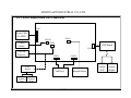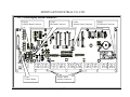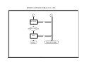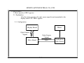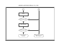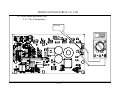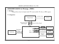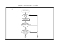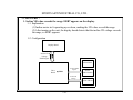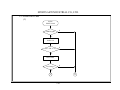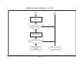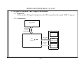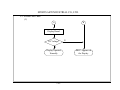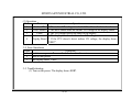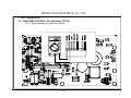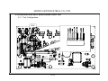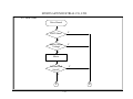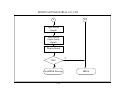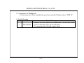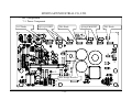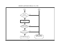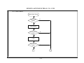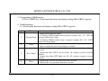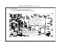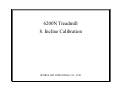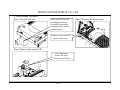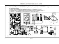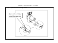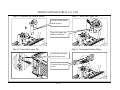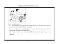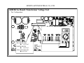
1
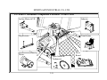
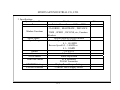
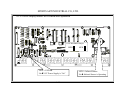
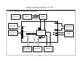
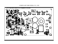
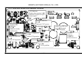
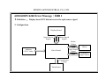
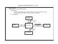
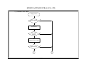
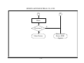
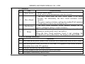
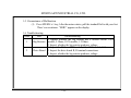
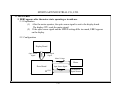
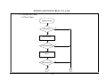
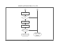
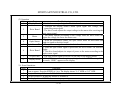
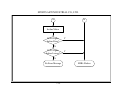
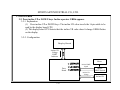
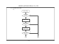
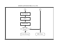
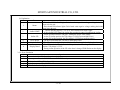
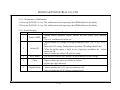
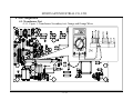
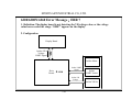
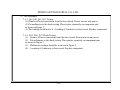
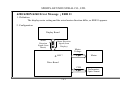
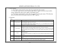
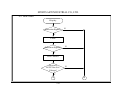
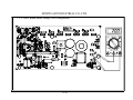
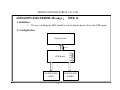
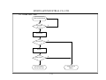
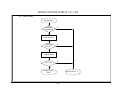
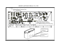
6200 Treadmill Repair Manual
SPORTS ART INDUSTRIAL CO., LTD.
SPORTS ART INDUSTRIAL CO., LTD.
6200 Treadmill Repair Manual
Table of Contents
1. Treadmill Illustration
1-1-1 6200N Treadmill Illustration
2. Electronic Component Locations
2-1-1 6200N Treadmill Component Location Illustration – Upper Part
2-2-1 6200N Treadmill Component Location Illustration – Lower Part
3. Introduction
3-1-1 Model Introduction
3-2-1 Main Functions
3-3-1 Specifications
4. Product Operation
4-1-1 6200N Treadmill Operation
4-2-1 Display Function Modes
5. Unit Block Diagrams
5-1-1 6200N Treadmill Configuration
5-2-1 Display Board Wire Connections
5-3-1 Drive Board Wire Connections
6. Basic Connections
6-1-1 Display Board Wire Connections
6-2-1 Drive Board Wire Connections
0-0-1
SPORTS ART INDUSTRIAL CO., LTD.
6200 Treadmill Repair Manual
Table of Contents
7. Error Messages / Troubleshooting
7-1-1 6200/6200N/6260 Error Message: ERR 1
7-2-1 6200/6200N/6260 Error Message: ERR 3
7-3-1 6200/6200N/6260 Error Message: ERR 6
7-4-1 6200/6200N/6260 Error Message: ERR 7
7-5-1 6200/6200N/6260 Error Message: ERR 10
7-6-1 6200/6200N/6260 Error Message: ERR 11
7-7-1 6200/6200N/6260 Error Message: ERR 12
7-8-1 6200/6200N/6260 Error: Infrared Sensor is Not Picking Up a Signal
7-9-1 6200/6200N/6260 Error: Unit Doesn’t React When STOP Pad is Pressed
8. Incline Set Recalibration
8-1-1 6200/6200N/6260 Incline Set Recalibration Procedure
9. No Start – Transformer Test
9-1-1 No Start – Transformer Test
0-0-2
6200N Treadmill
1. Treadmill Illustration
SPORTS ART INDUSTRIAL CO., LTD.
SPORTS ART INDUSTRIAL CO., LTD.
6200N Treadmill Illustration
1-1-1
6200N Treadmill
2. Electronic Component Locations
SPORTS ART INDUSTRIAL CO., LTD.
SPORTS ART INDUSTRIAL CO., LTD.
2-1. 6200N Treadmill Component Location Illustration – Upper Part
Display
Infrared Sensor
Filter
HTR Handlebar
2-1-1
SPORTS ART INDUSTRIAL CO., LTD.
2-2. 6200N Treadmill Component Location – Lower Part
Incline Motor & VR
Inductor
Big Resistor
Transformer
Motor
Optic Sensor &
Tachometer
2-2-1
Drive
Board
6200N Treadmill
3. Introduction
SPORTS ART INDUSTRIAL CO., LTD.
SPORTS ART INDUSTRIAL CO., LTD.
3. Model Introduction
3-1. Introduction
6200N Treadmill is a club unit with microcomputer control. Functions include calorie and
distance count, heart rate, time, speed, and incline.
The 6200N Treadmill has a low speed of 0.2 KPH (0.1 MPH) and a high speed of 20.0 KPH
(12.0 MPH). In addition to forward motion, the 6200N Treadmill walk belt can also operate in
reverse, at speeds from a low of 0.2 KPH (0.1 MPH) to a high of 5.0 KPH (3.0MPH).
The 6200N Treadmill has an infrared sensor that detects whether a user is on the unit.
If no one stands on the treadmill, the display enters a wait mode. If the sensor detects a user,
the display goes into action.
The 6200N Treadmill has an advanced STOP touch switch. To stop the treadmill belt when in use,
lightly touch the STOP touch pad; the unit will stop all action.
The 6200N Treadmill simulates running on various incline surfaces. The highest incline level
is 22%, whereas the lowest level is -3% incline.
The 6200N Treadmill offers the use of two heart rate modes, the HTR handlebar and the POLAR
strap, both of which allow users to monitor their heart rate as they exercise.
3-1-1
SPORTS ART INDUSTRIAL CO., LTD.
2. Main Functions
2-1.Calorie Window Function
2-1-1. Shows the user calorie expenditure.
2-1-2. In Calorie expenditure countdown mode, at 0, the display “beeps” once.
2-2.Heart Rate Window Function
2-2-1. Shows the heart rate value.
2-2-2. Allows for use of the POLAR heart strap or built-in HTR handlebar.
2-3.Distance Window Function
2-3-1. Shows the distance covered by the user.
2-3-2. In Distance countdown mode, at 0, the display “beeps” once.
2-4.Time Window Function
2-4-1. Shows the length of time exercised.
2-4-2. In Time countdown mode, at 0, the display “beeps” once.
2-5.Speed Window Function
2-5-1. Shows the treadmill walk belt speed.
2-5-2. Treadmill walk belt speed setting ranges from a low speed of 0.2 KPH (0.1MPH)
and high speed of 20.0 KPH (12.0MPH).
2-5-3. Treadmill walk belt can operate in forward or reverse directions.
3-2-1
SPORTS ART INDUSTRIAL CO., LTD.
2-6.INCLINE Window Function
2-6-1. Shows incline position.
2-6-2. Incline setting is adjustable.
2-6-3. The highest incline setting is 22%; the lowest incline setting is -3%.
2-7. Infrared Sensor Function
2-7-1. Automatically detects whether a user is on the unit.
2-7-2. If no user is on the unit, the unit goes into “wait” mode; If a user is on the unit, all functions
are activated.
2-8. The TOUCH STOP Function
2-8-1. Lightly touch the STOP pad; The treadmill belt immediately stops operating.
2-8-2. A light touch is sufficient to operate the STOP function.
3-2-2
SPORTS ART INDUSTRIAL CO., LTD.
3. Specifications
Specifications Name
Power
Details
Exterior Power Source: 110V or 220V
CALORIES,HEARTRATE,DISTANCE
Window Functions
Speed Modes
Speed Range
Incline
Sensor
STOP Switch
Heart Rate Modes
KPH/MPH Setting
CARDIO Function
TIME,SPEED,INCLINE, etc., Function
Windows
Forward Motion; Reverse Motion
Forward Speed 0.2 - 20.0 KPH or
0.1 - 14.0 MPH
Reverse Speed 0.2 – 5.0 KPH or
0.1 - 3.0MPH
-3% to 22%
Infrared Sensor
Touch Stop Switch
HTR Handlebar
POLAR Transmitter
Display Board Jumper Setting
CARDIO Power Supply Socket
3-3-1
Notes
6200N Treadmill
4. Product Operation
SPORTS ART INDUSTRIAL CO., LTD.
SPORTS ART INDUSTRIAL CO., LTD.
6200N Treadmill Operation
1. Display Windows
Heart Rate Window
Time Window
ÎHeart Rate Value
ÎTime Display & Setting
Incline Window
Calorie Window
Î Incline Position
Display & Setting
ÎCalorie Display & Setting
Distance Window
Î Distance Display & Setting
STOP Switch
ÎStop Function
Speed Window
ÎSpeed Display & Setting
STOP Switch
ÎStop Function
4-1-1
SPORTS ART INDUSTRIAL CO., LTD.
4-1-2 Soft Key Locations
CALORIE Key
Î Set Calorie Goal
TIME Key
INCLINE Key
ÎSet Workout Time
DISTANCE Key
Î Set Distance
Î Set Incline Position
SPEED Key
Î Set Speed
RESET Key
Î Clear Display
4-1-2
SPORTS ART INDUSTRIAL CO., LTD.
2. Display Function Modes
1. CALORIE Window Functions:
Functions:1. Displays user calorie expenditure value
2. Set calorie count value
Explanation:1. Display board CPU calculates calorie expenditure using factors including TIME, SPEED, WEIGHT.
2. When set to count down calories, the display “beeps” once when the calorie expenditure goal is reached.
Operation:1. Press SPEED<▲>/<▼> key to set the SPEED value. The calorie window shows the Calorie value.
2. Press the Calorie <▲>/<▼> key to set the Calorie value. The calorie window resets and the display
beeps once.
3. HEART RATE window function:
Function:1. Display the user heart rate.
Explanation:1. Once the heart rate is detected, the heart rate window shows the heart rate value.
2. There are two ways to detect heart rate: by use of the POLAR strap or by holding the Heart Touch Rate Bar.
Operation:1. The user straps on the POLAR heart rate transmitter and exercises within 100 cm
of the display. The heart rate window shows the heart rate value.
2. The user holds the HTR bars, one in each hand. The heart rate value appears
on the display.
4. DIST Window
Function:1. Display the distance covered by the user.
2. Calorie count reset value.
4-2-1
SPORTS ART INDUSTRIAL CO., LTD.
Explanation:1. The display uses the TIME and SPEED value to calculate the distance.
2. When set to count down distance, the display makes a “beep” sound when
the distance value resets.
Operation:1. Press the Speed<▲>/<▼> keys to set the Speed value. In operation, the display
shows the distance covered.
2. Press the Dist<▲>/<▼> keys to set the distance countdown value. When the
distance window resets, the display makes a “beep” sound.
1. TIME Window
Function:1. Shows the length of time the user has exercised on the treadmill.
2. Set the time count reset value.
Explanation:1. The display automatically calculates the length of time in use.
2. In Time countdown mode, the display makes a “beep” sound
when the value resets.
Operation:1. Press the Speed<▲>/<▼> key to set the Speed value. In operation, the Time
window shows the length of the exercise time.
2. Press the Dist<▲>/<▼> key to set the Distance countdown value.
The display makes a “beep” sound when the Distance value resets.
2. SPEED Window
Function:1. Sets the treadmill speed.
2. Sets the direction of the treadmill walk belt.
Explanation:1. If the SPEED window shows a positive number, like “1.0” or “6.0”, the treadmill walk belt rotates for use in
a forward (not backward) direction.
2. In forward rotation, the speed range is 0.2-20.0 KPH or 0.1-12.0 MPH.
4-2-2
SPORTS ART INDUSTRIAL CO., LTD.
3. If the SPEED window shows a negative number, like “-1.0” or “–6.0”, the
treadmill operates for use in a reverse (backward) direction.
4. In reverse, the speed range is -0.2 to -5.0 KPH, or -0.1 to -3.0 MPH.
5. Press the SPEED<▲>/<▼> key to set the SPEED value.
6. In reverse, the highest incline is 3%.
Operation:1. To change from forward to reverse operation,
(1) press the SPEED<▲> key until the SPEED window shows 0.2 KPH (or 0.1 MPH).
The treadmill walk belt moves slowly.
(2) Continually press the SPEED<▲> key until the SPEED window shows 20.0 KPH (or 12.0 MPH).
The treadmill operates at high speed.
(3) Continually press the SPEED<▼> key until the SPEED window shows 0.2 KPH (or 0.1 MPH).
The treadmill slows until the slowest forward speed is reached.
2. Reverse Operation
(1) Simultaneously press Calories <▼>+Distance<▼> keys twice. The display makes a “beep” sound; the
SPEED window shows “-0.0” to indicate reverse mode.
(2) Press the SPEED<▲> key until the SPEED window shows “-0.2” KPH (or -0.1 MPH).
The treadmill belt moves in reverse at low speed.
(3) Press SPEED<▲> until the SPEED window shows “-5.0” KPH (or -3.0 MPH).
The treadmill belt operates in reverse at a higher speed.
(4) Press the SPEED<▼> key until the SPEED window shows “-5.0” KPH (or -3.0 MPH).
The treadmill walk belt slows.
(5) Continuously press the INCLINE<▲> key. The INCLINE rises to the 3% position.
4-2-3
SPORTS ART INDUSTRIAL CO., LTD.
6. INCLINE Window
Function:1. Shows the present treadmill incline position.
2. Sets the treadmill incline position.
Explanation:1. The display automatically calculates the unit incline position.
2. Press the incline key to set the incline position.
3. Incline position ranges from -3% to 22%.
Operation:1. Press the INCLINE<▲> key until the INCLINE window shows 22%.
The unit incline rises to the highest position.
2. Press the INCLINE<▼> key until the INCLINE window shows 0%.
The unit incline falls to the level position.
3. Press the INCLINE<▼> key until the INCLINE window shows -3%.
The incline falls to the lowest (a negative) position.
7. RESET Key
Function:1. Resets all display functions.
2. Clears all display windows to the 0 value, except for incline.
Explanation:1. Press the RESET key; the windows erase to 0, except for incline.
2. All display functions stop operating and reset.
Operation:1. Press the <RESET> key. The display makes a “beep” sound once.
Various windows flash. Display values clear to 0 (except for incline).
8. The Infrared Sensor Function
Function:1. Inspects whether anyone is standing on the treadmill before starting the display.
4-2-4
SPORTS ART INDUSTRIAL CO., LTD.
Explanation:1. If the infrared sensor switch is set to “0”, the infrared sensor does not operate.
The display operates normally.
2. If the infrared sensor switch is set to “1”, the infrared sensor is activated.
3. When the infrared sensor is activated, if no one is standing on the treadmill ,
the display windows show “----” and the unit does not operate.
4. When the infrared sensor is activated and someone is on the treadmill, the display
windows show “0000” and all functions operate.
Operation:1. With the infrared sensor switch set to the “off” position,
(1)
Set the infrared sensor switch to “0”. Stand on or off the treadmill, the display
shows 0.
2. With the infrared sensor set to the “on” position,
(1)
Set the infrared sensor switch to “1”. Don’t stand on the treadmill. The treadmill
Display shows “----”. Press any key. The treadmill doesn’t operate.
(2)
Stand on the treadmill. The display windows show “0000”. Press any key.
The treadmill operates normally.
6. STOP Switch
Function:1. Stops all treadmill operation.
Explanation:1. When the display left or right STOP switch is hit, the drive and incline motor
functions immediately stop.
2. The SPEED window shows 0. The INCLINE window shows the incline
position at the time the unit stopped operating.
4-2-5
SPORTS ART INDUSTRIAL CO., LTD.
Various window values stop counting. Values remain on the screen and do not show 0.
Operation:1. Press SPEED<▲> key. The treadmill belt starts moving. Calorie, Distance, and
Time windows start counting.
2. Tap the display STOP switch. The motor stops turning. The SPEED window shows 0.0.
Window values remain.
4-2-6
6200N Treadmill
5. Unit Block Diagrams
SPORTS ART INDUSTRIAL CO., LTD.
SPORTS ART INDUSTRIAL CO., LTD.
5-1. 6200N Treadmill Configuration
Soft Keys
STOP Board
CARDIO Board
POLAR
Receiver
Display Board
HTR
Handlebar
HTR Board
STOP Switch
(Left,Right)
Motor
Filter
FUSE
Switch
Optic Sensor
Drive Board
Incline Motor
Inductor
VR Set
Transformer
5-1-1
Big Capacitor
SPORTS ART INDUSTRIAL CO., LTD.
5-2. Display Board Wire Connections
Soft Keys
CARDIO
Board
POLAR
HR Receiver
Display Board
Infrared
Sensor
HTR
Board
HTR
Handlebar
(Left)
STOP
Board
HTR
Handlebar
(Right)
STOP
Switch
(Left)
Drive Board
5-2-1
STOP
Switch
(Right)
SPORTS ART INDUSTRIAL CO., LTD.
5-3. Drive Board Wire Connections
Display Board
Motor
Filter
FUSE
Switch
Optic Sensor
Drive Board
Incline Motor
Inductor
VR Set
Transformer
5-3-1
Big Resistor
6200N Treadmill
6. Basic Connections
SPORTS ART INDUSTRIAL CO., LTD.
SPORTS ART INDUSTRIAL CO., LTD.
6-1-1. 6200N Display Board Wire Connections
CON1
20-pin Cable
(To DRV)
CON9
CON14
CARDIO
Board
CON5
STOP Board
CON11
POLAR
Receiver
CON8
HTR
Board
HTR
Handlebar
(Left)
CON10
Soft Keys
HTR
Handlebar
(Right)
6-1-1
Infrared Sensor
STOP
Switch
(Left)
STOP
Switch
(Right)
SPORTS ART INDUSTRIAL CO., LTD.
6-1-2. 6200 Display Board PCB Component Locations
6-1-2
SPORTS ART INDUSTRIAL CO., LTD.
6-1-3. 6200 Display Board Connectors
CON 14
CARDIO Board Connector
CON1
To Drive Board
CON5
HR Board Connector
CON8, CON10
CON8,CON10
Soft Key Connector
軟性按鍵插座
6-1-3
CON9
Infrared Sensor Connector
CON11
STOP Board Connector
SPORTS ART INDUSTRIAL CO., LTD.
6-1-4. 6200N Display Board LED Location and Explanation
CON7 KPH/MPH Jumper
MPH
LED1 = POWER
Lit ÎVCC Power Supply is “On”
6-1-4
KPH
LED3 = Infrared Sensor
Lit Î Infrared Sensor is Operating
SPORTS ART INDUSTRIAL CO., LTD.
6-2-1. 6200 Drive Board Wire Connections
Power Cord
Filter
FUSE
Switch
R
CON4
20 PIN
Big Resistor
AC2
CON2
CON1
R
L1
CON6
Filter
MM+
L2
CON5
6 PIN
Cable
(to Display
Board)
CON3
Incline Motor
and VR Set
2 PIN
6 PIN
10 PIN
Optic Sensor
AC1
Transformer
6-2-1
Inductor
Motor
SPORTS ART INDUSTRIAL CO., LTD.
6-2-1. 6200 Drive Board PCB Component Locations
6-2-2
SPORTS ART INDUSTRIAL CO., LTD.
6-2-3. 6200 Drive Board LED Indicator Locations
CLK Indicator
Flashes then remains lit Î
Indicates reception of optic
sensor signal
Incline ERR
Indicator
Lit Î
Indicates incline
malfunction
Incline UP Indicator
Lit Î
Incline UP operation
POWER Indicator
Lit Î
Indicates VCC power
Motor Direction LED
Not lit ÎForward
Lit Î Backward
Incline UP Indicator
Lit Î
Incline UP operation
POWER
Indicator
Lit ÎVCC
Power circuit on
EMG Indicator
Lit Î
Circuit problem
6-2-3
6200N Treadmill
7. Error Messages / Troubleshooting
SPORTS ART INDUSTRIAL CO., LTD.
SPORTS ART INDUSTRIAL CO., LTD.
6200/6200N/6260 Error Message:ERR 1
1. Definition: Display board CPU did not receive the optic sensor signal.
2. Configuration
Optic Sensor
Signal
16 PIN
Display Board
Motor Speed
Signal
Motor
Voltage
2 pin
Inductor
(220 V Only)
Drive Board
Optic Sensor
Signal
4 pin
Transformer
Voltage
Transformer
7-1-1
Motor
Tachometer
Optic Sensor
SPORTS ART INDUSTRIAL CO., LTD.
3. Cause of ERR1
1. The motor doesn’t turn; ERR1 appears.
1-1. Explanation
The drive board did not sent voltage to the motor, so the motor didn’t operate.
And the display board didn’t receive the optic sensor signal.
2-1. Configuration
Display
Board
16 pin
Motor Speed
Signal
Motor Voltage
Inductor
(220 V Only)
2 pin
Drive Board
Transformer
Voltage
Transformer
7-1-2
4 pin
Motor
SPORTS ART INDUSTRIAL CO., LTD.
1-3. Operation
(1) Explanation
Order
Part
1
2
3
4
5
6
Circumstance of Malfunction
1. Press SPEED key; The display SPEED window shows “0.0”.
Display
2. Display board CPU sends the motor signal to the drive board to
control motor speed.
1. 220V models only.
Inductor
2. Sends the drive board AC rectified VH voltage to the motor drive
(220V)
circuit.
Transformer 1. Provides all power necessary to the motor drive circuit.
16-pin Cable The display board signal travels this cable to the drive board.
After processing the motor signal, the drive board sends power to
Drive Board
the motor, making the motor operate.
According to the voltage provided, the motor operates, which, in
Motor
turn, drives the treadmill walk belt.
7-1-3
SPORTS ART INDUSTRIAL CO., LTD.
(1) Action Flow Chart
Display Board
SPEED Signal?
N
Y
Transformer
Secondary
Voltage?
N
Y
Inductor (220 V Only)
Short Circuit?
N
Y
A
B
7-1-4
SPORTS ART INDUSTRIAL CO., LTD.
A
B
Drive Board
No
Yes
Motor Voltage?
Motor
No
Yes
Motor
Rotates
Motor Doesn't Rotate
Display Shows ERR1
7-1-5
SPORTS ART INDUSTRIAL CO., LTD.
1-4. Error Simulation
Order
Operation
1
Don’t turn on power. Remove the M+ and M- wires.
2
3
4
Turn on power. Press SPEED<▲> or <▼> keys. The display shows “0.1” MPH or
“0.2” KPH.
The motor doesn’t operate.
The display immediately shows “ERR:1”.
1-5. Circumstance of Malfunction
(1) Press SPEED<▲> or <▼> keys. The walk belt doesn’t move. The display shows “ERR:1”.
1-6. Troubleshooting
Order
Part
1
2
3
4
Troubleshooting
1. Press down firmly on the program IC.
Display Board
2. Inspect whether the 16-pin cable is connected securely.
16-pin Cable 1. Test by replacing the cable with a good one.
1. Reconnect the inductor wires.
Inductor
2. Inspect whether the inductor has a short.
1. Inspect the transformer wire connections.
Transformer
2. Test the transformer voltage.
7-1-6
SPORTS ART INDUSTRIAL CO., LTD.
5
6
1. Inspect wire connections to the drive board, including
transformer and inductor.
2. Put multimeter probes separately on drive board M+ and MDrive Board
terminals. Press SPEED key. Inspect whether there is voltage.
3. If not, the drive board is bad or the signal from the display to the
drive board is in question.
1. If the drive board puts out voltage, and the motor doesn’t
operate, then the motor is bad.
2. Inspect whether the motor has a broken circuit: disconnect motor
Motor
M+ and M- wires from the drive board; put probes on the motor
M+ and M- wires.
3. Inspect the motor wire connections.
4. Inspect the motor brushes.
7-1-7
SPORTS ART INDUSTRIAL CO., LTD.
3. Cause of ERR1
2. Motor operates; ERR1 appears.
2-1. Explanation
After the motor operates, the optic sensor signal is not transmitted to the
display board CPU. ERR1 appears.
2-1. Configuration
Display Board
16 pin
Optic Sensor
Signal
Motor
Optic Sensor
Signal
Drive Board
4 pin
7-1-8
Tachometer
Optic Sensor
SPORTS ART INDUSTRIAL CO., LTD.
2-3. Operation
(1) Explanation
Order
Part
Troubleshooting
1
Motor
1. After pressing the SPEED key, the motor operates.
Tachometer 1. The motor movement makes the tachometer rotate.
2
Optic Sensor 2. The optic sensor detects the tachometer speed.
1. The optic sensor signal travels the 4-pin cable to the display
3
4-pin Cable
board.
1. After the optic sensor signal is processed, the drive board CLK
4
Drive Board indicator lights.
2. The drive board emits the optic sensor signal to the display board.
The optic sensor signal travels from the drive board to the display
5
16-pin Cable
board.
1. The CPU reads the optic sensor signal. If there is an optic sensor
signal, the CPU emits the motor speed signal.
6
Display Board 2. If the CPU doesn’t detect the optic sensor signal, the display
shows “ERR1” and stops sending the motor speed signal to the
drive board.
7-1-9
SPORTS ART INDUSTRIAL CO., LTD.
(2) Action Flow Chart
Motor
Rotation?
N
Y
Optic Sensor
CLK Indicator?
N
Y
Drive Board
CLK Indicator
Flashes?
N
Y
A
B
7-1-10
SPORTS ART INDUSTRIAL CO., LTD.
A
B
Cable
CLK Indicator?
N
Y
Drive Board
CLK Indicator?
N
Y
Motor Operates
Normally
Motor Operates, then
ERR1 Appears
7-1-11
SPORTS ART INDUSTRIAL CO., LTD.
2-4. Error Simulation
Order
Operation
1
Don’t turn on power. Remove the optic sensor wire connections.
2
3
4
5
Turn on power. Press SPEED<▲> or <▼> keys. The display board shows “0.1” MPH or “0.2”
KPH.
Motor speeds uncontrolled.
Drive board CLK indicator doesn’t light.
The display board immediately shows “ERR:1”. The motor stops rotating.
2-5. Circumstance of Error
(1) Press SPEED<▲> or <▼> keys. The motor speeds up uncontrolled. The display shows
“ERR:1”.
(2) Press the SPEED<▲> or <▼> keys. The motor operates. The display shows “ERR1:1”.
2-6. Troubleshooting
Order
Part
1
Motor
2
Tachometer
Optic Sensor
Troubleshooting
1. Press the SPEED key and inspect whether the motor operates.
1. Inspect whether the tachometer is fastened securely and rotating in the
middle of the optic sensor.
2. Inspect whether the tachometer teeth are broken or bent.
3. Inspect whether the optic sensor has been hit or damaged.
4. Inspect whether the optic sensor signal reaches the drive board: When the
tachometer wheel rotates, the drive board CLK indicator flashes or remains
lit.
7-1-12
SPORTS ART INDUSTRIAL CO., LTD.
3
Optic Sensor
Wire (4-pin)
4
Drive Board
5
Cable
6
Display Board
1. Perform a continuity test on the optic sensor wire to detect
whether it is broken.
2. Test optic sensor by replacing it with an optic sensor that has
worked properly on another treadmill.
1. Inspect whether the CLK indicator flashes or remains lit when
the motor rotates.
2. Inspect the 16-pin cable. Inspect whether the optic sensor wire is
connected securely.
3. Or replace the drive board.
1. To test the cable, replace it with a good one.
1. Inspect the cable connections.
2. Press down on the display board motor IC.
3. Or replace the display board.
7-1-13
SPORTS ART INDUSTRIAL CO., LTD.
4. Test Configuration
4-1. Transformer Test
4-4-1. Figure 1: Drive Board Transformer Test
7-1-14
SPORTS ART INDUSTRIAL CO., LTD.
Figure 2. Red to Red Wire (or Blue to Blue Wire)
Figure 3. Black to Black Wire
Figure 4. White to White Wire
Figure 5. Orange to Orange Wire
7-1-15
SPORTS ART INDUSTRIAL CO., LTD.
6200/6200N/6260 Error Message:ERR 3
1. Definition
1. The SPEED setting and the actual speed differ too much. ERR3 appears.
2. Configuration
Optic Sensor Signal
16 PIN
Display Board
Motor Speed Signal
Motor Voltage
Motor
Big Resistor
FUSE
Drive Board
Optic Sensor
Signal
Optic Sensor
7-2-1
SPORTS ART INDUSTRIAL CO., LTD.
3. Cause of ERR3
1. Unit resistance function doesn’t operate; display shows ERR3.
1-1. Explanation
(1) When the treadmill incline is up to the 7% position or more, centrifugal force acts
on the walk belt, making it move faster than the speed setting.
(2) When the drive board detects a faster optic sensor speed, resistance is produced to
decrease the walk belt speed.
(3) If the resistor produces no effect, the treadmill walk belt speeds up. The display
shows
ERR3.
2-1. Configuration
Resistance Voltage
Big Resistor
Motor
Voltage
Motor
Drive Board
CLK Signal
Optic Sensor
7-2-2
SPORTS ART INDUSTRIAL CO., LTD.
2-3. Cause of ERR3
Motor and
Optic Sensor
Is Motor Speed
Abnormal?
N
Y
Y
Drive Board
F2 Fuse
Shorted Out?
N
Y
Resistance
Voltage?
N
Y
Big Resistor
Resistor Broken
Circuit?
N
Y
A
7-2-3
B
SPORTS ART INDUSTRIAL CO., LTD.
A
B
Motor
Resistance?
N
Y
Motor Rotates
7-2-4
Motor Doesn't
Rotate; ERR1
Appears
SPORTS ART INDUSTRIAL CO., LTD.
1-3. Operation
Order
Part
Troubleshooting
1. Detects motor speed.
1
Optic Sensor
2. Sends motor speed information to the drive board.
1. The drive board reads the optic sensor signal. If the motor
becomes fast abnormally, the drive board resistance circuit
2
Drive Board
operates.
2. The motor creates resistance, making the treadmill belt maintain
a steady speed, with no way to drag the belt.
1. The drive board resistance circuit operates through the big
3
Big Resistor
resistor, causing the motor to create resistance.
When the drive board resistance circuit operates, the belt
maintains a steady speed even if one pulls it.
4
Motor
When the drive board resistance circuit is not operating, the
treadmill belt can be pulled faster. The display will show ERR3.
1-4. Error Message Simulation
Order
Operation
1 Don’t turn on the power. Remove the resistorRwire connections from the drive board.
2
3
4
5
Turn on the power. Press INCLINE<▲> key until 15% appears in the incline window.
The incline rises to the 15% position.
Press the SPEED key; the motor rotates.
Pull the treadmill walk belt with your feet as you walk.
The display immediately shows ERR3.
7-2-5
SPORTS ART INDUSTRIAL CO., LTD.
1-5. Circumstance of Malfunction
(1) Press SPEED<▲> key; After the motor rotates, pull the treadmill belt with your feet.
There’s no resistance. “ERR3” appears on the display.
1-6. Troubleshooting
Order
Part
1
2
Troubleshooting
1. Inspect whether the big resistor has a broken circuit: 220V
Big Resistor models, 5 Ohms; 110V models, 1.5 Ohms.
2. Inspect whether the big resistor produces voltage.
1. Inspect the F2 fuse. 220V models, 5A; 110V models, 10A.
Drive Board 2. Inspect the drive board R, R terminal connections.
3. Inspect whether the big resistor produces voltage.
7-2-6
SPORTS ART INDUSTRIAL CO., LTD.
3. Cause of ERR3
2. ERR3 appears after the motor starts operating or in mid-use.
2-1. Explanation
(1) After the motor operates, the optic sensor signal is sent to the display board.
The display CPU reads the motor signal.
(2) If the optic sensor signal and the SPEED setting differ too much, ERR3 appears
on the display.
2-2. Configuration
Optic Sensor
Signal
16 pin
Display Board
Motor Speed
Signal
Motor Voltage
2PIN
Drive Board
Motor
Optic Sensor Signal
CLK
4 pin
7-2-7
Tachometer
Optic Sensor
SPORTS ART INDUSTRIAL CO., LTD.
2-3. Action Flow Chart
(1) Flow Chart
Display Board
Operation?
N
Y
Drive Board
CLK Indicator?
N
Y
Motor
Motor Speed?
N
Y
A
B
7-2-8
SPORTS ART INDUSTRIAL CO., LTD.
A
B
Optic Sensor
N
CLK?
Y
Cable
Display Board
Speed Variance?
N
No ERROR Message
7-2-9
Y
After the Motor
Operates, ERR3
Appears
SPORTS ART INDUSTRIAL CO., LTD.
(2) Operation
Order
Part
1
Display Board
2
3
4
5
6
7
6
Troubleshooting
1. Sends the motor speed signal to the drive board.
1. Converts the display board’s motor speed signal into voltage, thus
controlling motor speed.
Drive Board
2. The drive board adjusts the output voltage to the motor after receiving the
optic sensor signal.
1. The motor operates according to the voltage from the drive board: the
Motor
higher the voltage, the faster the motor runs.
1. When the tachometer rotates, the optic sensor notes the movement and
Optic Sensor
sends its signal to the drive board.
Optic Sensor Wire 1. The optic sensor signal travels to the drive board.
1. After the optic sensor signal is processed, the drive board CLK indicator
lights.
Drive Board
2. The drive board adjusts its output of power to the motor according to the
optic sensor signal.
16-pin Cable 1. The optic sensor signal travels the 16-pin cable to the display board.
1. If the CPU detects that the optic sensor signal and the SPEED setting differ
Display Board
too much, “ERR3” appears on the display.
2-4. Error Simulation
Order
Operation
1
Turn on power. Press the SPEED<▲> key. The display shows “0.1” MPH or “0.2” KPH.
2
Use your feet to pull the treadmill belt faster.
3
The drive board CLK indicator flashes or remains lit.
4
The display shows “ERR3”; the motor stops operating.
7-2-10
SPORTS ART INDUSTRIAL CO., LTD.
2-5.Circumstance of Malfunction
(1) Press the SPEED<▲> key. Don’t stand on the treadmill. The display immediately
shows “ERR3”.
(2) Press the SPEED<▲> key. The treadmill walk belt moves, and “ERR3” immediately
appears.
2-6. Troubleshooting
Order
Part
1
2
3
4
Troubleshooting
1. Press down on the motor program IC.
Display Board 2. Inspect the 16-pin cable and its connections.
3. Replace the motor program with a more recent edition.
1. Inspect whether the tachometer is fastened securely and rotating
in the middle of the optic sensor.
Tachometer
Optic Sensor 2. Inspect whether the optic sensor teeth are in tact.
3. Test by replacing with a good optic sensor.
Motor
1. Inspect the motor or replace it with one that is good.
1. Inspect the 16-pin cable and connections. Inspect the optic sensor
Drive Board
wire.
2. Test by replacing with a good drive board.
7-2-11
SPORTS ART INDUSTRIAL CO., LTD.
4-1. Big Resistor Test
4-1-1. Test Configuration
7-2-12
SPORTS ART INDUSTRIAL CO., LTD.
4-1-2. Test Procedure
(1) Remove the big resistor. Don’t connect its wires to the drive board.
(2) Put multimeter to the 200 Ohm setting. Place proves as shown.
(3) If there’s no reading or an OL reading, the large resistor has a broken circuit.
7-2-13
SPORTS ART INDUSTRIAL CO., LTD.
4-2. Drive Board Resistance Test
4-2-1. Test Configuration
F2 Fuse
7-2-14
SPORTS ART INDUSTRIAL CO., LTD.
4-2-2. Test Procedure
(1) Don’t remove drive board wire connections.
(2) Put multimeter to the DC 200 Volt setting. Place the probes as shown on the drive board
R and R terminals.
(3) Turn on the power. Press the SPEED UP key so the walk belt rotates.
(4) If the multimeter shows voltage, then the drive board resistance is operating.
(5) If the multimeter has no reaction whatsoever, the drive board has no resistance.
7-2-15
SPORTS ART INDUSTRIAL CO., LTD.
6200/6200N/6260 Error Message:ERR 6
1. Definition
During incline action, the display board CPU cannot read the VR value, so ERR6 appears.
2. Configuration
INCLINE UP/DN
Soft Keys
Incline VR Voltage
LIMIT Signal
16 PIN
Display Board
Incline Up/Down Signal
LED4(UP)
Transformer
Voltage
Transformer
Drive
Board
FUSE
Incline Motor Voltage
LED3(DN) Incline LIMIT Signal
LED5(ERR)
Incline Motor
Incline
LIMIT Switch
Incline VR
Voltage
Incline VR
7-3-1
SPORTS ART INDUSTRIAL CO., LTD.
3. Cause of ERR6
3-1. Press the incline UP or DOWN key. The incline doesn’t operate. ERR6 appears on the display.
3-1-1. Explanation
(1) Press the incline UP or DOWN key. The drive board UP or DN indicator lights.
The incline operates, moving the VR, which changes the VR value.
(2) The display board CPU reads the incline VR value. If there is no VR value change, to the
CPU, the incline is not operating when it should be. ERR6 appears on the display.
3-1-2. Configuration
INCLINE UP/DN
Soft Keys
Incline VR Voltage
LIMIT Signal
16 PIN
Display Board
Incline Up/Down Signal
LED4(UP)
Transformer
Voltage
Transformer
Drive
Board
FUSE
Incline Motor Voltage
LED3(DN) Incline LIMIT Signal
LED5(ERR)
Incline Motor
Incline
LIMIT Switch
Incline VR
Voltage
Incline VR
7-3-2
SPORTS ART INDUSTRIAL CO., LTD.
3-1-3. Action Flow Chart
(1)
Display Board
Incline
UP/DN?
N
Y
Drive Board
During UP Action,
LED4 Lights, Incline
Voltage Increases
N
Y
In DOWN Action,
LED3 Lights
Incline Voltage
Decreases
N
Y
A
B
7-3-3
SPORTS ART INDUSTRIAL CO., LTD.
A
B
Incline Motor
LED4 Lights
Incline Rises?
Y
N
LED3 Lights
Incline Lowers?
Y
N
No Error Message
7-3-4
ERR6 Flashes
SPORTS ART INDUSTRIAL CO., LTD.
(2) Operation
Order
Part
1
Display
2
16-pin Cable
3
Transformer
4
5
Drive Board
(ERR Indicator)
Incline Motor
Operation
1. Press INCL<▲> or INCL<▼> keys. Incline window shows incline value.
2. The CPU sends the UP/DOWN signal to the drive board.
1. The incline signal travels the 16-pin cable from the display board to the drive board.
1. The transformer supplies the drive board incline circuit all power needed for incline
operation.
1. Press the INCL<▲> key. The drive board UP indicator lights. Press the INCL<▼> key.
The drive board DN indicator lights.
2. LED4(UP) indicator lights. The drive board emits positive voltage to make the incline
motor raise the unit.
3. LED3(DN) indicator lights. The drive board emits negative voltage to make the incline
motor lower the unit.
4. LED5(ERR) LED lights to indicate that the incline has exceeded the range or
malfunctioned.
1. When the drive board UP LED lights, the incline motor is in upward operation.
2. When the drive board DN LED lights, the incline motor is in downward operation.
3-1-4. Error Simulation
Order
Operation
1
Don’t turn on the power. Remove the incline fuse.
2
Turn on the power. Press the INCLINE<▲> or INCLINE<▼> key.
3
Drive board Up or DN indicator lights.
4
Incline doesn’t operate.
5
Display shows ERR6.
3-1-5. Circumstance of Malfunction
(1)
Press INCLINE<▲> key; The incline doesn’t rise. ERR6 flashes on the display.
(2)
Press the INCLINE<▼> key; The incline doesn’t lower . ERR6 flashes on the display.
7-3-5
SPORTS ART INDUSTRIAL CO., LTD.
(3) Press INCLINE<▲> or <▼> keys. The incline makes an odd sound. ERR6 flashes on the display.
(4) Press INCLINE<▲> or <▼> keys. The incline fuse blows. ERR6 flashes on the display.
3-1-6. Troubleshooting
Item
Part
Troubleshooting
1. Press incline <▲> key. The drive board UP LED lights.
Display Board 2. Press incline <▼> key. The drive board DN LED lights.
3. If not as above, press down on the display board CPU or inspect the cable and
connections.
1. Inspect whether the 16-PIN cable is connected well.
2
16-pin Cable
2. Test by replacing the cable with a good one.
3
Transformer 1. Test whether the transformer orange wires have AC 27 V.
Inspect whether the drive board ERR LED is lit.
Drive Board 1. Press incline UP or DOWN key again, making the incline motor return to its
4
(ERR LED Lit) position.
2. If ERR6 still appears, recalibrate the incline set.
Drive Board 1. Press the INCL<▲>/<▼> key. Inspect whether the drive board UP/DN LED is lit.
5
(ERR LED 2. When the drive board UP or DN LED is lit, inspect the incline motor terminals for
Not Lit)
output voltage.
6 Incline Fuse 1. Inspect the incline fuse and replace if necessary.
1. Inspect whether the incline motor is stuck.
2. Inspect whether the incline gears are cracked.
7 Incline Motor
3. Test whether the incline motor has a broken circuit.
4. Recalibrate the incline set and VR.
1
7-3-6
SPORTS ART INDUSTRIAL CO., LTD.
3. Causes of ERR6
3-2. Press incline UP or DOWN keys. Incline operates. ERR6 appears.
3-2-1. Explanation
(1) Press incline UP or DOWN keys. The incline VR value travels the 16-pin cable to be
read by the display board CPU.
(2) The display board CPU detects that the incline VR value doesn’t change. ERR6 flashes
on the display.
3-2-2. Configuration
Incline VR
Voltage
LIMIT
Indicator
16 PIN
Display Board
LED4(UP)
Drive
Board
LED3(DN)
Motor
Incline LIMIT
Signal
Incline
LIMIT Switch
LED5(ERR)
Incline VR
Voltage
Incline VR
7-3-7
SPORTS ART INDUSTRIAL CO., LTD.
3-2-3. Action Flow Chart
(1)
Incline Motor
UP/DOWN
Action?
N
Y
Incline LIMIT
LED5 Doesn't
Light?
N
Y
Incline VR Set
VR Voltage
Change?
N
Y
A
B
7-3-8
SPORTS ART INDUSTRIAL CO., LTD.
A
B
Drive Board
Cables
Display Board
VR Voltage
Change?
N
Y
No Error Message
7-3-9
ERR6 Flashes
SPORTS ART INDUSTRIAL CO., LTD.
(2) Explanation
Order
1
Part
Motor
2
Incline LIMIT
3
Incline VR
4
5
Drive Board
16-pin Cable
6
Display Board
Operation
1. Drive board UP indicator lights. Drive board emits positive voltage, making the incline
motor raise the unit.
2. Drive board DN indicator lights. Drive board emits negative voltage, making the incline
motor lower the unit.
1. Incline operates properly (-3 to 22%); Drive board LED5 doesn’t light.
2. If drive board LED5 lights, the incline has exceeded its range. Recalibrate the incline.
1. Incline operation turns the VR gears, making the incline value change.
2. At the 0% incline position, the VR voltage is 1.20V(Green and blue wires)
3. At the 22% incline position, the VR voltage is 3.55V(Green and blue wires)
1. The drive board sends the VR value to the display board.
1. The VR value travels the 16-pin cable from the drive board to the display board.
1. The CPU reads the VR value. At the -3% position, the VR voltage is 1.20V. At the 22%
position, VR voltage is 3.55V.
2. During incline operation, if the VR value doesn’t change, ERR6 flashes on the display.
3-2-4. Error Simulation
Order
Operation
1
Remove the incline VR. Don’t fasten it to the incline motor.
2
Turn on power. Press the INCLINE<▲> or INCLINE<▼> key.
3
The drive board UP or DN indicator lights.
4
The incline operates UP or DOWN.
5
ERR6 flashes on the display.
7-3-10
SPORTS ART INDUSTRIAL CO., LTD.
3-2-5. Circumstance of Malfunction
(1) Press the INCLINE<▲> key. The incline motor starts operating, then ERR6 flashes on the display.
(2) Press the INCLINE<▼> key. The incline motor starts operating, then ERR6 flashes on the display.
3-2-6. Troubleshooting
Order
Part
1
Incline LIMIT
2
Incline VR
3
Drive Board
4
Cable
5
Display Board
Troubleshooting
1. During incline operation, inspect whether the drive board LED5 indicator
lights.
2. If it is lit, recalibrate the incline set.
1. Test the incline VR voltage on the green and blue wires. -3% = 1.20V. 22% =
3.50V.
2. Inspect the VR voltage. During incline operation, VR voltage should vary.
3. When the incline motor is stuck or out of position, recalibrate the incline
motor and VR.
4. Inspect whether the incline VR gears are stuck.
1. Test the drive board CON2 incline VR (green and blue wires) voltage
1. Inspect the wire connections.
2. Inspect whether the wires are pinched or broken.
3. Replace the cable and retest.
1. Inspect the cable connections.
2. Inspect whether the U8 IC pins are connected well.
3. Inspect whether the U9 IC pins are connected well.
7-3-11
SPORTS ART INDUSTRIAL CO., LTD.
4. Test Configuration
4-1. Transformer Test
4-1-1. Figure 1: Transformer Secondary test: Orange and Orange Wires
7-3-12
SPORTS ART INDUSTRIAL CO.,LTD.
4-1-2. Test Procedure
(1) Put the multimeter to the AC 200V setting. Place probes on the drive board CON1
transformer connector orange wires as shown.
(2) Turn on the power. Normal voltage: 26.0-29.0 V.
(3) If there is no voltage, the transformer is bad.
7-3-13
SPORTS ART INDUSTRIAL CO., LTD.
GREEN
WHITE
YELLOW
YELLOW
RED
GREEN
BLUE
4-2. Drive Board Incline Motor Voltage Test
4-2-1. Test Configuration
7-3-14
SPORTS ART INDUSTRIAL CO., LTD.
4-2-2 Test Procedure
(1) Put the multimeter to the DC 200V setting. Place the red probe on the CON2 WHITE-wire
pin. Place the black probe on the CON2 GREEN-wire PIN.
(2) Turn on the power switch. The display lights.
(2) Press the INCL<▲> key. The drive board LED4 indicator lights. The meter shows +35V or
more. The incline motor operates, lifting the unit.
(4) Press the INCL<▼> key. The drive board LED3 indicator lights. The meter shows -35V or
more. The incline motor operates, lowering the unit.
(5) If LED3 or LED4 lights, and there is no incline voltage, K2 or K3 are bad.
7-3-15
SPORTS ART INDUSTRIAL CO., LTD.
6200/6200N/6260 Error Message:ERR 7
1. Definition: The display board is not detecting the VR voltage value, or the voltage
value has exceeded the range. “ERR7” appears on the display.
2. Configuration
Incline VR
Voltage
LIMIT Signal
16 PIN
Display Board
Incline Motor
Drive
Board
Incline LIMIT
Signal
ERR
Incline
LIMIT Switch
Incline VR
Voltage
Incline VR Set
7-4-1
SPORTS ART INDUSTRIAL CO., LTD.
3. Cause of ERR 7
1. Incline VR value exceeds the range. ERR7 appears on the display.
1-1. Explanation
(1) Incline motor isn’t operating up or down, making the VR value exceed the range.
(2) After turning on the unit, the display board detects that the incline VR voltage exceeds
the range, so ERR7 appears.
1-2. Configuration
Incline VR
Voltage
LIMIT Signal
16 PIN
Display Board
Incline Motor
Drive
Board
Incline LIMIT
Signal
ERR
Incline
LIMIT Switch
Incline VR
Voltage
Incline VR Set
7-4-2
SPORTS ART INDUSTRIAL CO., LTD.
1-3. Action Flow Chart
(1)
Incline
LIMIT Switch
LIMIT Signal?
N
Y
Incline VR
1.0V< VR <3.7V?
N
Y
Drive Board
VR Voltage?
N
Y
A
B
7-4-3
SPORTS ART INDUSTRIAL CO., LTD.
A
B
Cable
VR Voltage?
N
Y
Display Board
1.0V< VR >1.5V
?
N
Y
Normal Incline
Operation
7-4-4
ERR7 Appears
SPORTS ART INDUSTRIAL CO., LTD.
(2) Operation
Order
Part
Operation
1
Incline VR 1. Incline VR voltage travels the incline VR wire to the drive board.
2
Drive Board 1. Sends the incline VR voltage to the display board.
1. CPU detects VR voltage. Normal range: 1.15-3.60V.
3
Display Board 2. If the VR voltage exceeds the range, “ERR7” appears on the
display.
1-4. Error Simulation
Order
Operation
1
Don’t turn on the power. Short out the drive board blue and green wires.
2
Turn on power.
3
The display immediately shows “ERR7”.
1-5. Malfunction
(1) Turn on the power; the display immediately shows ERR7.
1-6. Troubleshooting
Order
Part
1
Incline VR
Troubleshooting
1. Test whether the incline VR exceeds the range (1.15V-3.65V).
2. If the VR voltage exceeds the range, recalibrate the incline set.
7-4-5
SPORTS ART INDUSTRIAL CO., LTD.
2
Display Board
1. Inspect the display board cable connections.
2. Replace IC ADC 0804.
7-4-6
SPORTS ART INDUSTRIAL CO., LTD.
2 VR Signal Is Disrupted; ERR7 appears on the display.
2-1. Explanation
(1) The incline VR signal is disrupted, so the CPU cannot detect the signal. “ERR 7” appears.
2-2. Configuration
Incline VR
Voltage
LIMIT Signal
16 PIN
Display Board
Incline Motor
Drive
Board
Incline LIMIT
Signal
ERR
Incline
LIMIT Switch
Incline VR
Voltage
Incline VR Set
7-4-7
SPORTS ART INDUSTRIAL CO., LTD.
2-3. Action Flow Chart
(1)
Incline VR
N
1.10V<VR<3.7V?
Y
Drive Board
VR Voltage?
N
Y
Cable
VR Voltage?
N
Y
A
B
7-4-8
SPORTS ART INDUSTRIAL CO., LTD.
2-3. Action Flow Chart
(1)
A
B
Display Board
VR Voltage?
N
Y
Display Operates
Normally
7-4-9
ERR7 Appears on
the Display
SPORTS ART INDUSTRIAL CO., LTD.
(2) Operation
Order
Part
Operation
1
Incline VR 1. The incline VR voltage travels the VR cable to the drive board.
2
Drive Board 1. The drive board sends the incline VR voltage to the display board.
3
Cable
1. The VR voltage travels the cable to the display.
1. The display board reads the incline VR voltage.
4
Display Board 2. If the CPU doesn’t detect incline VR voltage, the display shows
“ERR7”.
2-4. Error Simulation
Order
Operation
1
Don’t turn on power. Remove the drive board incline wires.
2
Turn on unit power.
3
The display shows “ERR7”.
2-5. Troubleshooting
(1) Turn on the power. The display shows ERR7.
7-4-10
SPORTS ART INDUSTRIAL CO., LTD.
2-6. Troubleshooting
Order
Part
1
2
3
4
Troubleshooting
1. Reconnect VR wires.
Incline VR
2. Inspect whether the incline wires are broken or disconnected.
1. Inspect the incline wire and 16-pin cable connections.
Drive Board
2. Test whether the VR voltage varies at the incline wire terminal.
1. Inspect the wire connections.
Cable
2. Inspect whether wires are broken or crimped.
3. Replace the wires and test again.
1. Inspect the display board 16-pin connections.
Display Board 2. Press down on the main IC.
3. Replace IC ADC0804.
7-4-11
SPORTS ART INDUSTRIAL CO., LTD.
7-4-12
GREEN
WHITE
YELLOW
YELLOW
RED
GREEN
BLUE
4. Test Configuration
4-1. 6200/6200N/6260 Drive Board Incline VR Test
4-1-1. Place multimeter probes as shown.
SPORTS ART INDUSTRIAL CO., LTD.
4-1-2. Test Procedure
2-1. Put the multimeter to the DC 20V setting. Place probes as shown on drive board CON2
blue and green wire connectors.
2-2. Turn on the power. Normal voltage: 1.10V to 3.60. If the voltage exceeds this range, ERR 7
appears on the display.
2-3. Press the INCL<▲> key until the incline window shows 15%. The treadmill incline rises
to the highest position. Voltage is 3.60V.
2-4. Press the INCL<▼> key until the incline window shows -3%. The treadmill incline lowers
to the lowest position. Voltage is 1.20V.
2-5. If not as above, readjust the incline set.
2-6. If during incline action, the multimeter shows unstable VR voltage, replace the VR.
7-4-13
SPORTS ART INDUSTRIAL CO., LTD.
4-2.6200/6200N/6260 Drive Board Incline LIMIT Test
4-2-1. Test Configuration
7-4-14
WHITE
GREEN
YELLOW
YELLOW
RED
GREEN
BLUE
LED5
SPORTS ART INDUSTRIAL CO., LTD.
4-2-2. Drive Board LIMIT Signal Test
(1) Turn on the power. Remove the incline wire from the drive board CON2 connector.
The drive board LED5 indicator lights.
(2) Reconnect the incline wire to the drive board CON2 connection. Short the both yellow
incline wires. Drive board LED5 indicator doesn’t light.
(3) If as above, the drive board LIMIT signal operation is normal.
(4) If not as above, the drive board LIMIT signal is abnormal.
4-2-3. Incline LIMIT Switch Signal Test
(1) Press the INCL<▲> key until the incline window shows 22%. The incline rises to the 22%
position. The drive board LED5 indicator doesn’t light.
(2)
Press the INCL<▼> key until the incline window shows -3%. The incline lowers to the
0%
position. The drive board LED5 indicator doesn’t light.
(3) If in operation from 0-15%, the drive board ERR indicator lights,
(1) recalibrate the incline set;
(2) inspect the incline LIMIT wire and connection;
(3) replace the incline VR.
7-4-15
SPORTS ART INDUSTRIAL CO., LTD.
6200/6200N/6260 Error Message:ERR 10
1. Definition
The motor speeds uncontrolled. Display shows ERR 10.
2. Configuration
Display Board
CLK
Signal
Motor
Voltage
Motor
CLK
Signal
Drive Board
Optic Sensor
7-5-1
SPORTS ART INDUSTRIAL CO., LTD.
3. Cause of ERR10
3-1. If the motor speeds uncontrolled, the optic sensor signal speed increased abnormally.
3-2. The display board reads the optic sensor signal. If the optic sensor signal increases
abnormally, ERR10 appears on the display.
3-3. The cause of uncontrolled motor speed is an IGBT short. The drive board protective
feature could not compensate. So as soon as the treadmill is turned on, the motor speeds
uncontrolled.
4. Operation
4-1.
Order
Part
1
Drive Board
2
Motor
3
Optic Sensor
4
Drive Board
5
Display Board
Operation
1.When the unit is turned on, drive board M+, M- wires are not sending any
voltage to the motor.
2. If IGBTs malfunction, the drive board M+, M- wires send voltage to the
motor.
3. The drive board automatically tests for IGBT shorts. If IGBT shorts are
found, LED6 indicator lights.
1. If the motor doesn’t receive voltage from the drive board, it doesn’t operate.
2. If, when you start the unit, drive board M+, M- wires send voltage
abnormally to the motor, the motor automatically speeds uncontrolled.
1. The optic sensor detects the motor speed and sends its signal to the drive
board.
1. The drive board sends the optic sensor signal to the display board.
1. The CPU reads the optic sensor signal.
2. If the speed signal indicates that the motor is speeding uncontrolled, the
display shows ERR10.
7-5-2
SPORTS ART INDUSTRIAL CO., LTD.
4-2. Flow Chart
Drive Board
Y
IGBT Short?
N
Motor Output
Voltage
Y
N
Motor
Uncontrolled
Speed?
Y
N
A
B
7-5-3
SPORTS ART INDUSTRIAL CO., LTD.
A
B
Optic Sensor
(Signal)
Drive Board
(Optic Sensor
Signal)
Display Board
CLK?
Y
N
No ERROR Message
7-5-4
ERR10
SPORTS ART INDUSTRIAL CO., LTD.
5. Circumstance of Malfunction
(1) Turn on power. Motor immediately speeds uncontrolled. Display shows “ERR 10”.
6. Troubleshooting
Order
Part
1
Troubleshooting
1. Remove the drive board wire connections. Test the drive board
Drive Board
power components Q11, Q12 for shorting.
2. If components have shorted, replace them.
7-5-5
SPORTS ART INDUSTRIAL CO., LTD.
7. Test Configuration
7-1. Power Component
D17 Diode
Q12,Q11
Q12,
Q11 IGBT
D16 Diode
BD1 Bridge Rectifier
7-5-6
Q10,Q9MOSFET
Q10,Q9
D15 Diode
SPORTS ART INDUSTRIAL CO., LTD.
7-2. Test Configuration
Figure 1. Q9, Q10, Q11, Q12 IGBT and MOSFET Test
Figure 2. D15, D16, D17 Diode
7-5-7
SPORTS ART INDUSTRIAL CO., LTD.
7-3. Test Procedure
7-3-1. Q9, Q10, Q11, Q12 Testing
(1) Remove all wire connections from the drive board. Do not turn on unit power.
(2) Put multimeter to the diode setting. Place probes separately on component pins
as shown in Figure 1.
(3) The reading should not be 0. A reading of 0 indicates a short circuit. Replace component.
7-3-2. D15, D16, D17 Diode Testing
(1) Remove all wire connections from the drive board. Do not turn on unit power.
(2) Put multimeter to the diode setting. Place probes separately on component pins
as shown in Figure 2.
(3) Multimeter readings should be as shown in Figure 2.
(4) A reading of 0 indicates a short circuit. Replace component.
7-5-8
SPORTS ART INDUSTRIAL CO., LTD.
6200/6200N/6260 Error Message:ERR 11
1. Definition
The display motor setting and the actual motor direction differ, so ERR11 appears.
2. Configuration
Motor
Direction
Signal (from
Motor)
16 PIN
Display Board
Motor Direction
Signal (from
Display)
Motor
Voltage
LED 7
2 pin
Motor
Drive Board
CLK
4 pin
7-6-1
Tachometer,
Optic Sensor
SPORTS ART INDUSTRIAL CO., LTD.
3. Cause of ERR11
3-1. The display board emits the motor direction signal to the drive board.
3-2. The optic sensor detects motor direction and sends its signal to the drive board, which,
in turn, transmits the optic sensor signal to the display board.
3-3. The display board reads the motor direction signal from the optic sensor. If the direction
differs from that which the display board sent, ERR11 appears.
4. Operation
4-1.
Order
Part
1
Display Board
2
Cable
3
Drive Board
4
Motor
5
Optic Sensor
6
Drive Board
7
Display Board
Operation
1. If the SPEED window shows a positive number, like “2.0”, the display board is emitting a
forward direction signal to the drive board.
2. If the SPEED window shows a negative number, like “-1.0”, the display board is emitting a
reverse direction signal to the drive board.
1. The direction signal travels the cable from the display board to the drive board.
1. LED7 on the drive board does not light when the drive board receives a forward direction
signal, and voltage for forward rotation travels the M+, M- wires to the motor.
1. LED7 on the drive board lights when the drive board receives a reverse direction signal
from the display board, and voltage for reverse motor rotation travels the M+, M- wires to
the motor.
1. When the drive board M+, M- voltage is for forward rotation, the motor rotates in a
forward direction.
2. When the drive board M+, M- voltage is for reverse rotation, the motor rotates in a reverse
direction.
1. Optic sensor detects motor rotation and emits its signal.
1. After reading the motor direction signal, the drive board transmits the signal to the display
board.
1. The CPU compares the SPEED direction setting and the motor signal from the optic sensor.
2. If the setting differs from the actual motor direction, ERR11 appears.
7-6-2
SPORTS ART INDUSTRIAL CO., LTD.
4-2. Flow Chart 1
Display
Direction Signal?
N
Y
Cable
Direction Signal?
N
Y
Drive Board
Forward:
LED7 Not Lit?
Voltage?
N
Y
A
B
7-6-3
SPORTS ART INDUSTRIAL CO., LTD.
A
B
Reverse
LED7 Lit?
Forward Voltage?
N
Y
Motor
LED7 Not Lit.
Forward Rotation?
N
Y
LED7 Lit
Reverse Rotation?
Y
No ERR Message
7-6-4
N
ERR11 Motor
Direction Error
SPORTS ART INDUSTRIAL CO., LTD.
4-3. Flow Chart 2
Motor Optic Sensor
Optic Sensor
Signal?
N
Y
Drive Board
Motor Direction
Signal?
N
Y
Cable
Motor Direction
Signal?
N
Y
A
B
7-6-5
SPORTS ART INDUSTRIAL CO., LTD.
A
B
Display Board
Forward Rotation =
LED7 Not Lit?
N
Y
Reverse Rotation =
LED7 Lit?
N
Y
No Error Message
7-6-6
ERR11
SPORTS ART INDUSTRIAL CO., LTD.
5. Circumstance of Malfunction
(1) Press SPEED key. Actual motor direction and display setting differ. ERR11 appears.
6. Troubleshooting
6-1. Actual motor direction and display setting differ. ERR11 appears.
Order
Part
1
Display Board
2
Cable
3
Drive Board
4
Motor
Troubleshooting
1. Inspect motor direction signal.
(1) Display SPEED window shows a positive number, like “1.0.” LED7 on
the drive board doesn’t light.
(2) Display SPEED window shows a negative number, like “-0.0”. LED7
on the drive board lights.
1. Inspect the cable connections.
2. Inspect whether the wires have broken or crimped.
1. Inspect whether the motor M+, M- wires are connected properly (not
crossed).
2. Inspect that when LED7 is not lit, the M+, M- voltage is positive (forward
rotation).
3. Inspect that when LED7 lights, the M+, M- voltage is negative (reverse
rotation).
1. When LED7 is not lit, the motor direction is forward.
2. When LED7 is lit, the motor direction is reverse.
7-6-7
SPORTS ART INDUSTRIAL CO., LTD.
6-2. SPEED window setting and the motor setting are the same, but the display shows ERR11.
Order
Part
Troubleshooting
1. Inspect whether the tachometer is missing teeth.
1
Optic Sensor
2. Replace the optic sensor.
2
Drive Board 2. Inspect whether the drive board U15 IC is normal.
3
Wire
1. Inspect whether the wire connected properly or crimped.
4
Display Board 1. Inspect whether U9 IC pins are contacting properly.
7-6-8
SPORTS ART INDUSTRIAL CO., LTD.
7. Test Configuration
7-1. Drive Board Motor Direction Indicator Test
7-1-1. Drive Board Motor Direction Indicator Location
M+,M(Motor Voltage)
LED7
馬達正反轉信號燈
LED7 Not Lit Î Forward Î Motor
不亮Î馬達正轉
Voltage is Positive (+)
亮
達 轉
LED7 Lit Î Reverse Î Motor
Vl
i N
LED7 Motor Direction Indicator
Not Lit Î Motor Operates Forward
Lit Î Motor Operates in Reverse
7-6-9
i
(
)
SPORTS ART INDUSTRIAL CO., LTD.
7-1-2. Drive Board Motor Voltage Test Configuration
7-6-10
SPORTS ART INDUSTRIAL CO., LTD.
7-1-3. Test Procedure
1. Put multimeter to the 220V DC setting. Place probes separately on drive board M+, M- terminals
as shown in Figure 1 (red probe on M+; black probe on M-).
2. Press the SPEED<▲> key. The display SPEED window shows “1.0” KPH. The drive board
LED7 doesn’t light. The multimeter shows 20V or more. The motor rotates in the forward direction.
3. Press the CAL<▼>+DIST<▼> keys. The SPEED window shows “-0.0”. The drive board LED7
lights. Press the SPEED<▲> key until the SPEED window shows “-1.0” KPH. The multimeter
shows “-20” V or more. The motor rotates in the reverse direction.
4. If the drive board LED7 doesn’t light, but the multimeter shows negative voltage, or the drive
board LED7 lights, but the multimeter shows positive voltage, the drive board is defective.
7-6-11
SPORTS ART INDUSTRIAL CO., LTD.
6200/6200N/6260 ERROR Message: ERR 12
1. Definition
1. The user is holding the HTR handlebar, but the display doesn’t detect the HTR signal.
2. Configuration
3 PIN
Display Board
PULSE
HTR Board
HANDLE BAR
(LEFT)
7-7-1
D3
D4
D5
D6
HANDLE BAR
(RIGHT)
SPORTS ART INDUSTRIAL CO., LTD.
3. Cause
3-1. The HTR board detects the pulse signal and the HTR signal is sent to the display board.
3-2. The display board detects the HTR signal. If there is none at the CPU, ERR 12 appears.
4. Action Flow Chart
4-1. Operation
Order
Part
HTR
1
Handlebar
2
3
4
Operation
1. The user holds onto the HTR handlebar. The pulse is transmitted to the
HTR board.
1. The HTR board detects whether the user is holding the HTR
handlebars with both hands. If so, the HTR board D4 indicator lights.
2. If the heart rate signal enters the board, the HTR board D5 indicator
HTR Board
flashes.
3. After the heart rate signal is processed, the HTR board D6 indicator
flashes.
1. The HTR signal travels the three-pin cable from the HTR board to the
3-PIN Cable
display board.
1. The CPU reads the heart rate signal and calculates the heart rate value.
2. The heart rate value appears in the PULSE window.
Display Board 3. If the CPU detects a heart rate signal but cannot calculate the heart
rate value, ERR 12 appears. ERR 12 tells the user to hold onto the
HTR handlebar more firmly, without moving.
7-7-2
SPORTS ART INDUSTRIAL CO., LTD.
4-2. Action Flow Chart
HTR HANDLEBAR
HTR Board
D3 Lit?
N
Y
HTR Board
D4, D5 Lit?
N
Y
Display
Pulse Value?
N
Y
PULSE Window
Shows HR Value
Display Shows
ERR12
7-7-3
SPORTS ART INDUSTRIAL CO., LTD.
5. Error Message Simulation
Order
1
2
3
4
Operation
Press the display <ON> key. The display “beeps” once and lights up. Main window shows
“MAN’L”.
Put both hands on the HTR handlebar.
Move your hands on the HTR handlebar so the heart rate cannot be detected.
“ERR 12” appears on the display.
6. Circumstances of Malfunction
6-1. The user places both hands on the HTR handlebar. The display shows “ERR 12”.
7. Troubleshooting
Order
1
2
3
4
Part
Troubleshooting
1. Inspect whether the HTR handlebar wire is shorting or broken.
Left, Right HTR 2. Hold onto the HTR hanblebar. Inspect whether the HTR board D4 indicator
Handlebar
lights and remains lit and whether the D5 indicator subsequently flashes. If not,
the HTR handlebar and/or wire are bad.
1. Hold onto the HTR handlebar.
2. If D4 indicator doesn’t light and D5 indicator doesn’t flash, the HTR handlebar
HTR Board
or wire are bad.
3. If D6 doesn’t flash or flashes erratically, the HTR board is bad.
1. Inspect the 3-PIN wire connections.
3-PIN Cable
2. Inspect whether the 3-PIN wire has shorted out or broken.
1. Inspect the 3-PIN wire connections.
Display Board
2. Inspect whether the U7 IC pins are connected well, or replace the IC.
7-7-4
SPORTS ART INDUSTRIAL CO., LTD.
8. HTR Board Test
8-1.HTR Board Wire Connections and LED Indicators
PO L A R
RECIV IER
CTL
D3
D4
HTR HA ND BA R
D5
D6
8-2. Explanation of LED Indicators
LED
Color
Name
D3
RED
POLAR HR LED
D4
YELLOW
D5
GREEN
D6
WHITE
Explanation
Flashes to indicate that POLAR heart rate signal
is entering the board.
HTR Signal LED
Lights to indicate that the user is holding the
HTR handlebar.
HTR PULSE LED Flashes to indicate the HTR heart rate is entering
the board.
PULSE Output LED Flashes each time a heart rate signal is emitted.
7-7-5
SPORTS ART INDUSTRIAL CO., LTD.
8-3. Test Procedure
8-3-1. Don’t hold the HTR handlebar. The HTR board signal indicator doesn’t light.
8-3-2. Hold the HTR handlebar with both hands. The HTR board D4 indicator lights.
8-3-3. Then the D5 indicator flashes, indicating that the HTR signal is entering the board.
8-3-4. Next, D6 indicator flashes to indicate that the HTR board is being sent to the display board.
8-3-5. Within ten seconds, the PULSE window shows the heart rate value.
8-3-6. If not as above, refer to troubleshooting.
Malfunction
Cause
Explanation
D3 Not Lit
No heart rate is entering the POLAR
receiver.
D4 Not Lit
No one is holding the HTR handlebar.
D5 Not Lit
No HTR signal is entering the unit.
D6 Not Lit
The HTR board didn’t emit the heart
rate signal.
No HR on Display The HTR board signal wasn’t sent to
the display board.
POLAR transmitter, POLAR receiver, cable
HTR handlebar, HTR board to handlebar cable
HTR handlebar, HTR board to handlebar cable
HTR board
3-PIN cable, display board
8-4. Circumstance of Malfunction
8-4-1. Place both hands on the HTR handlebar. The HR value doesn’t appear in the display PULSE window.
8-4-2. After turning on the unit, the PULSE window shows a value, while no one is holding the HTR handlebar.
8-4-3. Place both hands on the HTR handlebar. The display PULSE window heart rate value differs too much from
the user’s real pulse.
7-7-6
SPORTS ART INDUSTRIAL CO., LTD.
6200/6200N/6260 Error : Infrared Sensor is Not Picking Up a Signal
1. Definition
Display board infrared sensor does not detect the user on the treadmill.
2. Configuration
Transmitter
Signal
Infrared Sensor
(Transmit/Receive)
Display Board
Receiver
Signal
7-8-1
User
SPORTS ART INDUSTRIAL CO., LTD.
3. Cause
3-1. The infrared sensor transmits the infrared signal.
3-2. When a user is on the treadmill, the sensor detects the signal and transmits it to the display.
3-3. When the display doesn’t detect a user, the display shows “ ---- ”. When a user is detected,
the display shows ‘0000’.
4. Operation
Order
Part
Operation
1
Display Board 1. The infrared signal is sent to the infrared sensor.
1. When the infrared sensor switch is set to “0”, the infrared sensor
function is not activated.
2. When the infrared sensor switch is set to “1”, the infrared sensor
2
Infrared Sensor
function is activated.
3. When no one is on the treadmill, the display shows “----”.
4. When one stands on the treadmill, the display shows “0000”.
1. The CPU reads the infrared sensor signal.
3
Display Board 2. If no signal is received, the display shows “----”. If the signal is
received, the display shows “0000”.
7-8-2
SPORTS ART INDUSTRIAL CO., LTD.
4-2. Flow Chart
Display Board
Is Signal
Transmitted?
N
Y
Infrared Sensor
Transmit/
Receive?
N
Y
Display Board
Receive?
N
Y
Display Shows
"0000"
Display Shows "----"
7-8-3
SPORTS ART INDUSTRIAL CO., LTD.
5. Circumstance of Malfunction
(1) The user stands on the treadmill, but the display still shows “----”.
6. Troubleshooting
Order
Part
1
2
3
Troubleshooting
1. Inspect whether the infrared sensor cable is fastened securely.
Display Board
2. Replace X3 or U15, U16.
1. Inspect the infrared sensor on/off switch.
Infrared Sensor
2. Replace the infrared sensor transmitter or receiver.
1. Inspect the cable connections.
Cable
2. Test whether the 5-PIN cable is connected properly.
7-8-4
SPORTS ART INDUSTRIAL CO., LTD.
6. Test
7-1. Infrared Sensor Function Test
7-1-1. Illustration
X3
U15
U16
LED3 Infrared Sensor Indicator
Lit Î Infrared Signal is Operating
Not Lit Î Infrared Signal is Not Operating
Infrared Sensor
Transmitter
Infrared Sensor
Receiver
7-8-5
SPORTS ART INDUSTRIAL CO., LTD.
7-1-2. Test Procedure - Don’t Use the Infrared Sensor
(1) Turn on unit power.
(2) Flip the infrared sensor on/off switch to “0”, shutting off the infrared sensor function.
(3) The display shows “0000”. You can directly operate the treadmill.
(4) If the display shows “----”, you cannot operate the treadmill. The infrared sensor
5-pin cable is bad.
(5) Inspect the infrared sensor on/off switch.
7-1-3. Test Procedure - Use the Infrared Sensor Function
(1) Turn on the unit power.
(2) Flip the infrared sensor on/off switch to “1”, activating the infrared sensor function.
(3) Don’t stand on the treadmill; The display shows “----”. Stand on the treadmill;
the display shows “0000”.
(4) If not as above, inspect the infrared sensor wire connections.
(5) Replace the infrared sensor transmitter and receiver.
(6) Replace display board X13, U15, U16.
Infrared Sensor
On/Off Switch
7-8-6
SPORTS ART INDUSTRIAL CO., LTD.
6200/6200N/6260 Error : Unit Doesn’t React When STOP Pad is Pressed
1. Definition
1. Press the STOP switch (left or right); The display shows no reaction whatsoever.
2. In use, the treadmill stops suddenly, even though no one touched the STOP pad.
2. Configuration
Display Board
STOP
Signal
TOUCH
STOP Board
LED1
STOP
Signal
STOP
Signal
STOP Switch
(Left)
7-9-1
STOP Switch
(Right)
SPORTS ART INDUSTRIAL CO., LTD.
3. Cause
3-1. When the STOP board detects a signal, the TOUCH STOP board LED either lights or
extinguishes. The display stops all functions. The SPEED window shows 0.
Other window values remain unchanged.
3-2. If the STOP switch is malfunctioning, there is no reaction when the STOP switch is pressed,
or in mid-use the unit shuts off when no one hits the stop pad.
4. Operation
Order
1
2
3
Part
STOP Switch
(Left, Right)
TOUCH
STOP Board
Operation
1. Inspect whether the STOP switch was activated.
2. Inspect the Touch Stop Board.
1. If there is a STOP signal, LED1 on the Touch Stop Board lights or
extinguishes.
1. The CPU reads the STOP signal.
2. If there is a stop signal, all functions stop. The motor and incline
stop operating. SPEED window shows “0.0”; Various windows
Display Board
remain unchanged.
3. If the CPU doesn’t detect a stop signal, the display shows no
reaction whatsoever.
7-9-2
SPORTS ART INDUSTRIAL CO., LTD.
(2) Flow Chart
STOP Switch
(Left, Right)
STOP Signal?
N
Y
TOUCH STOP Pad
LED1
Lights/Extinguishes?
N
Y
Display Board
STOP Operates?
N
Y
Unit Stops
Windows Stop Counting
SPEED Shows 0.0
Display Board
No Stop Action
7-9-3
SPORTS ART INDUSTRIAL CO., LTD.
5. Circumstance of Malfunction
(1) Press the STOP switch. The treadmill motor and incline stop.
(2) In operation, the treadmill stops even though the stop board wasn’t hit.
6. Troubleshooting
Order
Part
1
2
3
Troubleshooting
1. Inspect whether the STOP switch wire is connected well.
STOP Switch
2. Inspect whether the STOP switch protective membrane is intact.
Pad
If not, it is susceptible to static interference.
1. Inspect whether the TOUCH STOP board is connected properly.
2. Press the STOP pad, or touch CON2 connector, LED1 lights or
TOUCH STOP
extinguishes.
Board
3. If there is no reaction, the TOUCH STOP board is
malfunctioning.
Display Board 1. Inspect whether U9 IC pins are connecting properly.
7-9-4
SPORTS ART INDUSTRIAL CO., LTD.
7. Test
7-1. TOUCH STOP Board
7-1-1. Illustration
LED1
STOP
STOPPad
開關按鍵
7-9-5
SPORTS ART INDUSTRIAL CO., LTD.
7-1-2. Test Procedure – Circumstance: The TOUCH STOP Is Not Functioning
(1) Inspect the wire and its connections from the STOP switch to the TOUCH STOP board.
(2) Turn on the unit power.
(3) Press the STOP pad once. The TOUCH STOP board LED1 indicator lights.
(4) If LED1 doesn’t light, the TOUCH STOP board is bad.
7-1-3. Test Procedure – Circumstance: In mid-use, the STOP board activates inappropriately.
(1) Inspect whether the STOP switch wires and ground wire are connected appropriately.
(2) Turn on the power.
(3) Press the SPEED<▲> key, making the treadmill belt move. Inspect whether
unit automatically stops when no one touches the STOP Pads.
(4) If the unit still stops inappropriately, remove the TOUCH STOP board CON2 connection.
If the unit still stops inappropriately, replace the STOP board.
7-9-6
6200N Treadmill
8. Incline Calibration
SPORTS ART INDUSTRIAL CO., LTD.
SPORTS ART INDUSTRIAL CO., LTD.
6200/6200N/6260 Incline Set Recalibration Procedure
1. Goal:
To recalibrate the incline set, making the incline operate properly.
2. Recalibration is needed when the following occur:
(1) Display shows ERR7;
(2) Display shows ERR6, and the drive board ERR indicator lights;
(3) The incline -3% or 22% position exceeds the range.
3. Recalibration method
(1) Calibrate the incline VR voltage to 1.20V.
(2) Calibrate the incline to the -3% position, so the end of the thick incline pipe meets
the red line on the thinner pipe.
8-1-1
SPORTS ART INDUSTRIAL CO., LTD.
4. Recalibration Procedure
Step 1. Prop up the unit.
Place a small box (180
mm high) under the
treadmill frame, thus
taking pressure off the
incline motor.
Remove screws, then lift
up the motor cover
Step 3. Remove the incline VR.
1. Don’t disconnect
incline VR wires.
2. Remove the VR box.
8-1-2
Step 2. Remove the motor cover.
SPORTS ART INDUSTRIAL CO., LTD.
8-1-3
GREEN
WHITE
YELLOW
YELLOW
RED
GREEN
BLUE
Step 4. Adjusting the Incline VR Voltage
(1) Put the multimeter to the 20V DC setting. Place probes separately on the CON2 blue and green wire connectors.
(2) Turn on unit power.
(3) Rotate the VR gear until the multimeter shows a VR voltage of 1.20V DC.
(4) Turn unit power off and then on again. The display INCLINE window shows “-3”.
(5) Put the VR back in place on the incline motor. Turn off unit power.
Gear
SPORTS ART INDUSTRIAL CO., LTD.
Step 5. Remove the Incline Motor
Step 6. Remove the Incline/Frame Pin
Disconnect Incline Set
Wires
Remove the
incline/frame lower
pin.
Step 7. Remove the Incline/Frame Pin
Step 8. Remove the Incline Set
Remove the
incline/frame upper
pin.
Remove the whole
incline set.
8-1-4
SPORTS ART INDUSTRIAL CO., LTD.
Step 9. Adjust the Incline Motor Pipe Position
Rotate until the end of the
thicker pipe is even with the
red line on the thinner pipe.
8-1-5
SPORTS ART INDUSTRIAL CO., LTD.
Step 10. Reinstall the Incline Motor
Step 11. Insert the Upper Pin
Put the incline motor
back in place.
Insert the upper pin
and its kotter pin.
Step 12. Insert the Lower Pin
Step 13. Reconnect Incline Wires
Insert the lower pin
and its kotter pin.
Connect like-colored
wires.
8-1-6
SPORTS ART INDUSTRIAL CO., LTD.
Step 14. Remove the Block
Step 15. Test the Incline Set
(1) Press the INCL<▲> key until the INCL window shows 22%. The incline rises to the 22%
position. Drive board LED5 indicator doesn’t light.
(2) Press the INCL<▼> key until the INC window shows -3%. The incline lowers to the -3%
position. The drive board LED5 doesn’t light.
(3) If when the incline operates, drive board LED5 doesn’t light, and at the -3% position the
end of the thick incline pipe meets the red line on the thin pipe, then recalibration has been
successful.
8-1-7
6200N Treadmill
9. No Start – Transformer Test
SPORTS ART INDUSTRIAL CO., LTD.
SPORTS ART INDUSTRIAL CO., LTD.
6200 Drive Board Transformer Voltage Test
1. Test Configuration
RED-RED
110V
BLACK-BLACK
Î 11-13VAC
WHITE-WHITE
Î 11-13VAC
YELLOW-YELLOW
Î11-13VAC
BLACK
11-13V
WHITE
11-13V
ORANGE YELLOW
27-29 10-12V