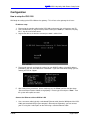
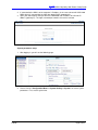
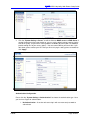
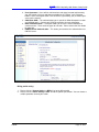
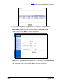
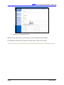
1
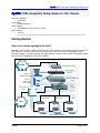
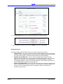
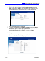
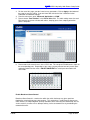
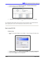
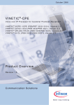
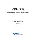
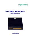
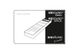
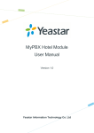
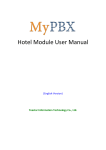
VDSL Hospitality
Setup Guide
For 100+ Rooms
VDSL Hospitality 100+ Rooms Setup Guide
Table of Contents
Table of Contents .....................................................................................2
Getting Started..........................................................................................3
What is the network topology in the hotel? ............................................................ 3
How to integrate the VSG-1200, ES-3024 and VLC1124L ....................................... 4
Before You Begin......................................................................................4
Why VDSL? ................................................................................................................ 4
VDSL basics............................................................................................................... 4
Installation.................................................................................................5
Telephone closet preparation................................................................................... 5
Proper Pin-Outs ......................................................................................................... 5
Connecting everything together............................................................................... 6
Configuration ............................................................................................8
How to setup the VSG-1200 ...................................................................................... 8
IP address setup................................................................................................................................. 8
Connect the Ethernet cable to WAN or LAN.................................................................................... 8
System parameters setup.................................................................................................................. 9
Authentication Configuration.......................................................................................................... 10
Billing profile setting........................................................................................................................ 11
Creating Accounts............................................................................................................................ 12
Setup LAN device management...................................................................................................... 13
How to setup the ES-3024....................................................................................... 14
IP address setup............................................................................................................................... 14
VLAN setup ....................................................................................................................................... 15
Enable Broadcast Storm Control.................................................................................................... 16
How to setup VLC1124L.......................................................................................... 17
IP address Setup .............................................................................................................................. 17
VLAN Setup....................................................................................................................................... 19
VDSL ports and profile setup.......................................................................................................... 20
Support....................................................................................................23
1/05/05
Page 2 of 23
VDSL Hospitality 100+ Rooms Setup Guide
VDSL Hospitality Setup Guide for 100+ Rooms
Subscriber Gateway
• VSG-1200
VLAN Switch
• ES-3024 (24 port)
VDSL DSLAM
• VES-2500 (with VLC-1124L line cards)
VDSL Modem
• P841-25
Getting Started
What is the network topology in the hotel?
Nowadays, most of hotels support the Internet service for customers. Some hotels provide the service for
free, while others charge users for service. Normally, the hotel’s Internet service topology includes a
broadband modem, subscriber gateway, managed switches, and an in-room solution. The diagram below
displays a typical topology for a hotel DSL network.
Internet
Broadband Gateway
Vantage Service
Gateway
Front Desk /
Management Computer
Dimension Managed
Switch
Property
Management
Server (PMS)
VDSL
Concentrator
Existing Hotel
PBX
VDSL CPE
VDSL CPE
VDSL
Telco
Hotel Guests in rooms
1/05/05
Page 3 of 23
VDSL Hospitality 100+ Rooms Setup Guide
How to integrate the VSG-1200, ES-3024 and VLC1124L
Here, we will guide you to configure the VSG-1200, ES-3024 and VLC1124L step by step. You can refer
these procedures to finish the environment easily, and provide the Internet service to your customer.
Before You Begin
Before you begin installation, it’s important to understand how the equipment is designed to work and
how it should be installed.
Why VDSL?
VDSL stands for Very fast Digital Subscriber Line. It is a form of DSL that allows for traffic throughput of
up to 15Mbps.
Although this is not as fast as the speed of Ethernet, which is usually 100Mbps and now available up to
1000Mbps, it can travel farther. Ethernet is limited to a maximum cable length of about 300 feet, whereas
VDSL can transmit on cable lengths up to about 4500 feet.
Like ADSL, VDSL allows use of voice and data on the same 2-conductor line. This means that a hotel
can leverage their existing cable infrastructure to provide guests with high-speed Internet, without the
additional cost of installing new wiring. Each room only needs a single pair of wire for both voice and
high-speed data.
Unlike ADSL, all configurations to the remote modems are done from the VDSL switch. This means that
there is less time spent configuring units, and fewer chances for miss-configuration. Customers also
cannot accidentally change the settings on the modem, since the VDSL switch programs the modem itself.
VDSL basics
To install VDSL, you must have two pieces of equipment:
A VDSL concentrator, also known as a VDSL Digital Subscriber Line Access Multiplexer
(DSLAM) or VDSL Central Office Equipment (COE)
A VDSL modem, also known as a VDSL Customer Premise Equipment (CPE)
The DSLAM is normally mounted inside a telephone closet, along with the hotel’s existing telephone PBX.
In each room, a VDSL modem is installed to which customers connect their computers via Ethernet port.
The DSLAM has two primary components in and of itself: a Splitter Chassis, and a Line Card Chassis.
Each component has a separate purpose and is needed for proper installation.
The splitter chassis contains splitter cards. Each splitter card has three Telco-50 ports, two in the rear,
and one in the front. One rear port acts as the input from the telephone PBX, while the other is the output
port which carries the voice/ data signal to the telephone room’s punchboard and, ultimately, to the
modem in each room. The front port connects directly to the line card in the Line Card Chassis.
1/05/05
Page 4 of 23
VDSL Hospitality 100+ Rooms Setup Guide
The Line Card Chassis contains one line card for each splitter card in the Splitter Chassis. VDSL line
cards (in this case VLC1124 cards) are installed into the chassis. The cards have two inputs, on Telco-50
port, and one Ethernet Uplink port. The Telco-50 port connects directly to the front of the corresponding
splitter card, and acts as an input and output for voice and data service. The Uplink port connects to an
Ethernet switch (usually a managed switch like an ES-3024 for VLAN purposes), and acts as the data
relay to the Internet.
Cards are hot-swappable, allowing for quick change-out without service disruption for users connected to
other cards. Each splitter card/ line card combo supports up to 24 ports, or modems.
In each room a VDSL modem is placed. The modem has an input from the wall outlet, and two outputs:
one phone port for an analogue telephone, and an Ethernet port for a computer connection. Because all
of the parameters are programmed in the line card, the modem has no settings to configure.
Installation
Telephone closet preparation
One of the trickiest parts with setting up a VDSL network is integrating it with the existing telephone
service. Although the ISP will usually take care of installing the Internet connection where you need it,
they will not help you install it with your in-building DSL solution.
Typically the telephone company providing the building’s voice service will contract installers to set up
and maintain in-building voice equipment and PBXs. Therefore, you will probably need to contact your
telephone company to have the contractor help install the necessary connectors for your voice service, if
they are not already present.
The input and output for all ZyXEL DSL DSLAM equipment is a standard Telco-50 connector. These
connectors are trapezoidal in appearance and contain 50 pins, which are paired up to provide the
necessary pair to each user or room. The contractor will need to terminate all connections coming from
the PBX to Telco-50 connectors in order for them to be properly connected to your VES equipment. Also,
the connections going to each room will also need to be terminated with Telco-50 connectors.
Typically, all of the PBX and room lines will be connected to a Main Distribution Frame (MDF) inside of
the telco closet. The MDF usually consists of two parts: an upper block for the incoming lines, and a
lower block for outgoing lines to users. These may or may not already be terminated into Teclo-50
connectors. Your Teclo-50 connectors will most likely be installed into this MDF. When wiring these
Telco-50 connectors, it is important that they be wired for the correct pin-outs, as explained below.
Proper Pin-Outs
The pin-outs for the Telco-50 connectors will depend on the VES equipment being used. Here is an
example pin-out from the VES-2500 DSLAM:
1/05/05
Page 5 of 23
VDSL Hospitality 100+ Rooms Setup Guide
Pin-outs are located in the Appendix section of your unit’s User’s Guide. Please be sure to have the
contractor refer to these when installing your Telco-50 connectors; otherwise, your VES installation will
not work properly.
For more information on with connectors apply to the PBX and to room connections, please read the next
section.
Connecting everything together
Once you have the proper Telco-50 Connectors in place, and the Internet connection has been installed,
you should be ready to connect your equipment.
1. First you should connect your modem to your internet connection (cable, DSL, T1, T3, etc.) if the
ISP has not already done so. If you require assistance in doing this, contact your ISP for further
help.
2. Once the modem is installed, connect your VSG-1200 to the modem via Ethernet cable. From
the LAN ports of the VSG, you will need to connect your ES-3024 managed switch via another
Ethernet cable. You may also connect management and employee computers to the other LAN
ports on the VSG per your preference.
3. From the ES-3024, you will connect your VES-2500 line cards. Each line card will have its own
Uplink port, which will need to be connected to one of the ports on the ES-3024 via Ethernet
cables.
4. Next, you will need to connect the telephone lines to the VES-2500. The Telco-50 connectors for
the VES-2500 can be confusing. In order for a successful installation, you’ll need the VES-2500
main chassis and the VES-2500 splitter chassis. Each line card of the VES-2500 will support up
to 24 lines or users. You will also need a splitter card for each line card used. Line cards are
installed into the main chassis, and splitter cards are installed into the splitter chassis.
5. Once the line cards and splitter cards are installed into their chassis, you’re ready to connect your
Teclo-50 cables. First, connect the VDSL port on the line card to the VDSL port in the splitter
card via Telco-50 patch cables, which have a male Telco-50 connector on each end.
6. On the back of the splitter chassis there are two Telco-50 ports for each splitter card. The once
marked “CO” will be the incoming voice lines from the building’s PBX. The once marked “USER”
is the outbound port for the lines going to each room. Below is a basic diagram of you the voice
service is connected through the splitter chassis’s rear connectors.
1/05/05
Page 6 of 23
VDSL Hospitality 100+ Rooms Setup Guide
Telco-50
Connector
PBX
MDF Upper
Block
VES-2500
Splitter Card
“CO”
Connector
VES-2500
Splitter Card
“USER”
Connector
MDF Lower
Block
Telco-50
Connector
Customer Rooms
7. Once you connect the rooms to the VES-2500 via the Telco-50 cables, each room’s telephone
port should be ready for modem installation. Install a Prestige 841 VDSL modem in each room
by connecting the unit’s “VDSL” port to the room’s telephone wall jack. You can then connect the
room’s phone to the “Phone” port on the back of the P841 for voice service. You should then
connect small length of Ethernet cable to each modem’s “LAN 10/100M” port for the customer’s
computer use. This way the P841 can split voice and data traffic, allowing room customers to use
the phone and Internet simultaneously.
8. Remember that all of your components will require their own power connection for operation, to
include each P841 modem in each room. Each unit will be supplied with the appropriate cables
or power adapters. Please ensure all units are powered on when in use.
9. If you are using a Property Management System (PMS) to track customer room charges, you
may want to connect this to the PMS port of the VSG-1200 as well. Although this document does
not describe how to set up the VSG-1200 for use with a PMS, you can find more information
about this in the VSG-1200 User’s Guide.
Be sure to use the diagram on page 3 as a basic reference for installation.
You should now be ready to configure your VSG-1200, ES-3024, and VES-2500 for use. For more
information about hardware installation, we strongly urge you to review the User’s Guides for the VSG1200, ES-3024, and VES-2500.
1/05/05
Page 7 of 23
VDSL Hospitality 100+ Rooms Setup Guide
Configuration
How to setup the VSG-1200
We’ll begin be setting up the VSG-1200 service gateway. This will act as the gateway for all users.
IP address setup
1. Please plug the console cable into the VSG-1200, and connect it to serial port on your PC.
2. Run a terminal tool (ex, HyperTerminal) and the settings are 9600 bps, 8 data bits, no parity
bits, 1 stop bit, and no flow control.
3. Log into the device; the default username/password is admin/1234.
4. Please enter menu 2, and insert the settings for your WAN IP address (the public address
provided by your ISP) and DNS Server information. If you don’t know what settings you use,
contact your ISP for support.
5. After setting these parameters, please continue press the “Enter” until the console shows
“S)ave and return R)eturn without saving M)odify:”. Please type “S” and press “Enter”. Then
the system will request to restart.
Connect the Ethernet cable to WAN or LAN
1. Use a crossover cable (typically a red-colored Ethernet cable) from the WAN port of the VSG1200, connected to directly to your computer’s Ethernet port. Alternately, you can connect
your PC using the 4 switch ports on the LAN using a standard Ethernet cable.
1/05/05
Page 8 of 23
VDSL Hospitality 100+ Rooms Setup Guide
2. If connected to the WAN, set the computer’s IP address in the same subnet with VSG-1200
WAN subnet. If connected to the LAN, then obtain DHCP automatically.
3. Open your web browser and input the VSG-1200 WAN side IP address or LAN side IP
address (gateway IP). The login username/password is the same as console.
System parameters setup
1. After logging in, you will see the following page.
2. Please click the “Configuration Menu >> System Setting >> System” to set the system
parameters. First, set the system time.
1/05/05
Page 9 of 23
VDSL Hospitality 100+ Rooms Setup Guide
3. Click the “System Setting >> Server” to edit the fields for DHCP server and DNS Server. If
you don’t know what values you should set, you can use the default setting; however, for the
sake of this guide, set your DHCP starting address to 10.59.1.30, with a pool size of 225 (to
provide enough IPs for your access points). You must enter DNS for your local side. If you
don’t know, please contact your ISP. After you finish this page’s setting, please remember to
click “Apply”.
Authentication Configuration
Please click the “System Setting >> Authentication” to choose the authentication type. Here
you can have 5 types of authentication:
1. No Authentication – Users do not have to log in with username and password to
authenticate.
1/05/05
Page 10 of 23
VDSL Hospitality 100+ Rooms Setup Guide
2. User Agreement – Users will be re-directed to a web page (created and hosted by
you) that contains the java code that we provide for the “I Agree” and “I Disagree”
buttons. Users must agree to the Terms of Service (specified by you) in order to gain
access to the internet.
3. CAS Hilton HSIA – This authentication type is specific for Hilton/Hampton Inn hotels
and affiliated hotels. Contact your HSIA representative for more information.
4. Built In Authentication – This option allows you to use the internal database to
create accounts. There are three types of scenarios. Please refer to the User Guide
for more info.
5. RADIUS Server Authentication – This allows you to redirect the authentication to a
RADIUS server.
Billing profile setting
1. Please click the “System Setting >> Billing” to set the billing profile
2. Please click the “Profile Setting >> Edit” to edit the profile’s parameters. You can choose a
suitable parameter to meet your needs.
1/05/05
Page 11 of 23
VDSL Hospitality 100+ Rooms Setup Guide
3. In the Edit Profile page, you can limit the bandwidth per customer account.
4. After finished the setting, please click the “Apply” to save this configuration.
Creating Accounts
If you chose Built-In Authentication, then you can create accounts in three ways:
• Thermal Printer – You can use the one-button and three-button printer to create dynamic
accounts. For the three-button printer, you can associate a different profile to each button,
for a total of three profiles. Username and password are created randomly.
• Dynamic Account Operator – You can create a separate admin login for Account
Operators that only have access to the Dynamic Account Operator page. There are three
buttons on this page that are associated to the first three billing profiles. To create a
corresponding account similar to using the thermal printer, click the button and then print
out the following pop-up page for account login info.
• Static Account Generation – You can create a range of static accounts by specifying the
pre-fix, range and post-fix for the username. The passwords are created randomly for all
accounts. You can also manually enter static accounts with the usernames and
passwords of your choice.
1/05/05
Page 12 of 23
VDSL Hospitality 100+ Rooms Setup Guide
After finished the setting, please click the “Apply” to save this configuration.
Setup LAN device management
You’ll need to add LAN device management entries to administrate devices on the LAN side of
the VSG-1200 from the LAN side. Use these steps to set up this feature for your ES-3024 switch:
1. Click on “Advanced Settings >> LAN Devices”.
2. In the first row, you’ll set up an account for you ES-3024 switch. First enter ES-3024 as the
Name. Then, type in 60001 as the Virtual Port. Set the Device IP Address to 10.59.1.2, and
the Device Server Port to 80. Finally, enter the MAC address from the ES-3024 in the Device
MAC Address filed (the ES-3024’s MAC address is a 12-character code found on the bottom
label of the unit, usually in a 00A0C5XXXXXX format). Leave the Application drop-down set
to TCP.
3. Click on “Apply” when finished.
4. You should now be able to administrate the ES-3024 through the VSG-1200’s public IP
address by typing the WAN address of the VSG-1200 into your web browser followed by
“:60001” For example: http://65.5.5.10:60001
1/05/05
Page 13 of 23
VDSL Hospitality 100+ Rooms Setup Guide
5. Repeat steps 2-4 for each of your VLC1124 VDSL line cards. Remember to use a unique
Virtual Port for each card. You can find the MAC address of the Line card on the bottom of
the card, or through the card’s web interface in the Statistics menu.
How to setup the ES-3024
IP address setup
1. The ES-3024 default IP address is the 192.168.1.1. You can enter this IP into your web
browser to access the unit’s web interface.
1/05/05
Page 14 of 23
VDSL Hospitality 100+ Rooms Setup Guide
2. You can change the IP address from web interface. Please from main menu to click the
“Basic Settings >> IP Setup”, to set the IP address.
3. Please set the IP address to 10.59.1.2, subnet mask to 255.255.255.0, the gateway to
10.59.1.1, and the DNS to 168.95.1.1. If you don’t know the DNS, you can set the value to
the VSG-1200’s IP address. Otherwise, contact your ISP for your DNS information.
4. Please click the “Apply” to save the configuration.
5. If you haven’t already done so, set up LAN Device Management in the VSG-1200 for the
ES-3024 switch. Refer to the material above for more information.
6. After you set the mapping table, please try to log into ES-3024 from WAN of VSG-1200 using
the VSG-1200’s WAN address and the Virtual Port assigned to the ES-3024.
VLAN setup
1. From the main menu, go to “Basic Settings >> Switch Setup”.
2. Please choose “Port Based” in the VLAN type drop-down field.
1/05/05
Page 15 of 23
VDSL Hospitality 100+ Rooms Setup Guide
3. For the rest of this page, you don’t need set any parameters. Click on Apply at the bottom of
the page to save this setting. If you are interested, refer to the User’s Guide for further
information on additional settings.
4. From the main menu, go to “Advanced Application >> VLAN”.
5. Please choose “Port Isolation” in the Preset Value field. This table setting means the each
Ethernet port cannot transmit data with others, keeping guests from snooping onto other
guests’ computers.
6. Please note on this menu there is also a “CPU” row. This row gives ES-3024 access rights to
the corresponding ports. Depending on your setup, you may want to have only certain ports
selected to administer the switch. DO NOT UNSELECT the switch port connected to the
VSG-1200.
Enable Broadcast Storm Control
Broadcast Storm Control is a mechanism within the switch that keeps any given port from
flooding the switch with too many data packets. This mechanism is used primarily when one or
more switches are looped together (to keep redundant traffic from being re-broadcasted), but can
also be useful if a hacker or virus attempts to deny service to network users by overloading the
network with traffic.
1/05/05
Page 16 of 23
VDSL Hospitality 100+ Rooms Setup Guide
1. From the main menu, go to “Advanced Application >> Broadcast Storm Control”.
2. Click on the Active box the enable the feature.
3.
Remember to click the Apply button on the bottom of the page to save your setting.
******
This configuration of the ES-3024 is quick and easy to set up and support. If you need to know more
details regarding other functions of the ES-3024, please refer to the User’s Guide.
How to setup VLC1124L
IP address Setup
1. The VLC1124L default IP address is the 192.168.1.1. You can change the IP address from
Web.
2. From main menu to click the “Getting Started >> IP Setup”, then do the IP setup. Set the
IP address to 10.59.1.3, the subnet mask to 255.255.255.0, and the gateway to 10.59.1.1.
3. Please click the “Apply” to save the configuration.
1/05/05
Page 17 of 23
VDSL Hospitality 100+ Rooms Setup Guide
4. If you haven’t already done so, set up LAN Device Management in the VSG-1200 for the
VLC1124 card. Refer to the material above for more information. You can find the MAC
address of the Line card on the bottom of the card, or through the card’s web interface in the
Statistics menu.
5. After you set the mapping table in the VSG-1200, please try to log into VLC1124L from WAN
side of your VSG-1200.
1/05/05
Page 18 of 23
VDSL Hospitality 100+ Rooms Setup Guide
VLAN Setup
1. Click the “Switch Setup” to edit the VLAN type. Please choose the “Port Based” from the
VLAN Type drop-down. Click the “Apply” to save the configuration.
2. Please click the “VLAN setup” to check the VLAN entries. Ensure that each port‘s Egress
settings are set only for itself and the Uplink port (the Uplink port should be set to itself and all
other ports). This setting means that rooms cannot transmit date to each other. The rooms
can only transmit data to the Uplink port.
1/05/05
Page 19 of 23
VDSL Hospitality 100+ Rooms Setup Guide
VDSL ports and profile setup
You are able to control priority and bandwidth on each VDSL port. Normally, all users will have
the same priority, but it may be necessary to change traffic priority or to increase or decrease the
transmission rate of users, in order to distribute bandwidth fairly or by priority. The following
steps outline how to adjust these settings.
1. Please click the “Port Setup >> Profile” to enter the VDSL profiles.
2. Please click the “Add” to add a new VDSL profile.
1/05/05
Page 20 of 23
VDSL Hospitality 100+ Rooms Setup Guide
3. You can name the profile per your preference (i.e.: Hotel-Guest). Please choose the
“10BaseS” of the VDSL mode, enable Rate Adaption, choose the Downstream/ Upstream
Max Line Rate for your supporting service, and enter the Payload rate for the
Downstream/Upstream. If you enter the value “10”, it means the bandwidth limited control is
1Mbps. Please click the “Apply” to save the configuration.
4. Please click the “Port Setup” link to edit the port’s parameters. Fill the characters in the
Name field (i.e.: Room101), enable the Active box, set the value “0” in the Default Priority
field and choose the Profile name that you just created in the VDSL field (i.e.: Hotel-Guest).
After completing all fields, please click the “Apply” to save the configuration.
1/05/05
Page 21 of 23
VDSL Hospitality 100+ Rooms Setup Guide
5. Repeat step 4 to setup other ports.
Repeat all of the steps for the VLC1124 setup for each card installed in your IES-2500.
If you would like to know the VLC1124L other settings, please refer the User’s Guide.
1/05/05
Page 22 of 23
VDSL Hospitality 100+ Rooms Setup Guide
Support
Now, if you followed the procedures to setup the VSG-1200, ES-3024 and VLC-1124Ls, your Internet
service should work in your environment. If you still have any problems, feel free to contact us:
North America - ZyXEL Communications Inc.
1130 North Miller Street, Anaheim, CA 92806-2001 U.S.A.
Toll Free: +1-800-255-4101
Tel: +1-714-632-0882
Fax: +1-714-632-0858
Email: [email protected]
http://www.us.zyxel.com
All contents copyright © 2004 ZyXEL Communications Corporation.
1/05/05
Page 23 of 23