1
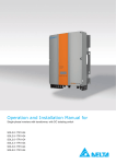
Operation and Installation Manual for
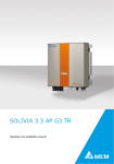
SOLIVIA 2.0 EU G4 TR
SOLIVIA 2.5 EU G4 TR
SOLIVIA 3.0 EU G4 TR
SOLIVIA 3.3 EU G4 TR
SOLIVIA 3.6 EU G4 TR
SOLIVIA 5.0 EU G4 TR
This manual applies to the following solar inverter types:
●
SOLIVIA 2.0 EU G4 TR
●
SOLIVIA 2.5 EU G4 TR
●
SOLIVIA 3.0 EU G4 TR
●
SOLIVIA 3.3 EU G4 TR
●
SOLIVIA 3.6 EU G4 TR
●
SOLIVIA 5.0 EU G4 TR
This manual can be amended at any time.
The latest version of this manual is available at www.solar-inverter.
com.
Delta Energy Systems (Germany) GmbH
Tscheulinstraße 21
79331 Teningen
Germany
© Copyright – Delta Energy Systems (Germany) GmbH – All rights
reserved.
This manual is included with our solar inverter and is intended for
use by the installer and end user.
The technical instructions and illustrations in this manual are to be
treated as confidential and no part of this manual may be reproduced without prior written permission from Delta Energy Systems.
Maintenance technicians and end users may not release the information contained in this manual, and may not use it for purposes
not directly associated with the proper use of the solar inverter.
All information and specifications can be modified without prior
notice.
2
Operation and Installation Manual for SOLIVIA 2.0/2.5/3.0/3.3/3.6/5.0 EU G4 TR
Table of Contents
Table of Contents
1. About This Manual . . . . . . . . . . . . . . . . . . . . . . . . . . . . . . . . . . . . . . . . . . . . . . . . . . . . 6
1.1
Purpose of This Manual . . . . . . . . . . . . . . . . . . . . . . . . . . . . . . . . . . . . . . . . . . . . . . 6
1.2
Target audience of this manual . . . . . . . . . . . . . . . . . . . . . . . . . . . . . . . . . . . . . . . . . . 6
1.3
Warnings and Symbols. . . . . . . . . . . . . . . . . . . . . . . . . . . . . . . . . . . . . . . . . . . . . . . 6
1.4
Conventions Used in This Document . . . . . . . . . . . . . . . . . . . . . . . . . . . . . . . . . . . . . . . 6
1.4.1
Order of Instructions . . . . . . . . . . . . . . . . . . . . . . . . . . . . . . . . . . . . . . . . . . 6
1.4.2
User buttons and LEDs . . . . . . . . . . . . . . . . . . . . . . . . . . . . . . . . . . . . . . . . 6
1.4.3
Information on Display . . . . . . . . . . . . . . . . . . . . . . . . . . . . . . . . . . . . . . . . . 6
2. Intended purpose . . . . . . . . . . . . . . . . . . . . . . . . . . . . . . . . . . . . . . . . . . . . . . . . . . . . . 7
3. General Safety Instructions . . . . . . . . . . . . . . . . . . . . . . . . . . . . . . . . . . . . . . . . . . . . . . . 9
4. Unpacking . . . . . . . . . . . . . . . . . . . . . . . . . . . . . . . . . . . . . . . . . . . . . . . . . . . . . . . . 10
5. Product Description . . . . . . . . . . . . . . . . . . . . . . . . . . . . . . . . . . . . . . . . . . . . . . . . . . .11
5.1
Overview of Components and Connections . . . . . . . . . . . . . . . . . . . . . . . . . . . . . . . . . . . .11
5.2
Type Plate . . . . . . . . . . . . . . . . . . . . . . . . . . . . . . . . . . . . . . . . . . . . . . . . . . . . 12
5.3
Status LEDs . . . . . . . . . . . . . . . . . . . . . . . . . . . . . . . . . . . . . . . . . . . . . . . . . . . 14
5.4
Display and Buttons . . . . . . . . . . . . . . . . . . . . . . . . . . . . . . . . . . . . . . . . . . . . . . . 14
5.5
5.4.1
Overview . . . . . . . . . . . . . . . . . . . . . . . . . . . . . . . . . . . . . . . . . . . . . . . 14
5.4.2
Display Layout . . . . . . . . . . . . . . . . . . . . . . . . . . . . . . . . . . . . . . . . . . . . 14
5.4.3
Buttons . . . . . . . . . . . . . . . . . . . . . . . . . . . . . . . . . . . . . . . . . . . . . . . . 14
5.4.4
General Menu Structure . . . . . . . . . . . . . . . . . . . . . . . . . . . . . . . . . . . . . . . 14
5.4.5
"Go to Menu" function . . . . . . . . . . . . . . . . . . . . . . . . . . . . . . . . . . . . . . . . 15
5.4.6
Button combinations . . . . . . . . . . . . . . . . . . . . . . . . . . . . . . . . . . . . . . . . . 15
5.4.7
Navigating the Menu . . . . . . . . . . . . . . . . . . . . . . . . . . . . . . . . . . . . . . . . . 15
5.4.8
Selecting a Submenu . . . . . . . . . . . . . . . . . . . . . . . . . . . . . . . . . . . . . . . . 15
5.4.9
Exiting a Menu
5.4.10
Setting Values . . . . . . . . . . . . . . . . . . . . . . . . . . . . . . . . . . . . . . . . . . . . 16
. . . . . . . . . . . . . . . . . . . . . . . . . . . . . . . . . . . . . . . . . . . 15
Electrical Connections . . . . . . . . . . . . . . . . . . . . . . . . . . . . . . . . . . . . . . . . . . . . . . 18
5.5.1
Overview . . . . . . . . . . . . . . . . . . . . . . . . . . . . . . . . . . . . . . . . . . . . . . . 18
5.5.2
DC connections and DC isolating switch . . . . . . . . . . . . . . . . . . . . . . . . . . . . . . 20
5.5.3
AC connection . . . . . . . . . . . . . . . . . . . . . . . . . . . . . . . . . . . . . . . . . . . . 20
5.5.4
RS485 interface (EIA485) . . . . . . . . . . . . . . . . . . . . . . . . . . . . . . . . . . . . . . 20
5.5.5
USB interface . . . . . . . . . . . . . . . . . . . . . . . . . . . . . . . . . . . . . . . . . . . . 20
6. Operating Behavior . . . . . . . . . . . . . . . . . . . . . . . . . . . . . . . . . . . . . . . . . . . . . . . . . . . 21
6.1
General Principle of Operation . . . . . . . . . . . . . . . . . . . . . . . . . . . . . . . . . . . . . . . . . . 21
6.2
Impact of DC Input Voltage . . . . . . . . . . . . . . . . . . . . . . . . . . . . . . . . . . . . . . . . . . . 21
6.3
Configuring Permanent Active and Reactive Power Reduction . . . . . . . . . . . . . . . . . . . . . . . . . 21
6.4
Functions Affecting Operating Behavior . . . . . . . . . . . . . . . . . . . . . . . . . . . . . . . . . . . . . 21
6.5
Balancing Asymmetrical Grid Loads . . . . . . . . . . . . . . . . . . . . . . . . . . . . . . . . . . . . . . . 21
6.6
Data Analysis and Communication. . . . . . . . . . . . . . . . . . . . . . . . . . . . . . . . . . . . . . . . 21
6.7
Characteristic Curves . . . . . . . . . . . . . . . . . . . . . . . . . . . . . . . . . . . . . . . . . . . . . . 23
7. Installation. . . . . . . . . . . . . . . . . . . . . . . . . . . . . . . . . . . . . . . . . . . . . . . . . . . . . . . . 24
7.1
7.2
Planning the Installation . . . . . . . . . . . . . . . . . . . . . . . . . . . . . . . . . . . . . . . . . . . . . 24
7.1.1
General Instructions . . . . . . . . . . . . . . . . . . . . . . . . . . . . . . . . . . . . . . . . . 24
7.1.2
Ambient Conditions . . . . . . . . . . . . . . . . . . . . . . . . . . . . . . . . . . . . . . . . . 25
7.1.3
Consideration of Asymmetrical Grid Load . . . . . . . . . . . . . . . . . . . . . . . . . . . . . . 25
Mounting Solar Inverter . . . . . . . . . . . . . . . . . . . . . . . . . . . . . . . . . . . . . . . . . . . . . 27
7.2.1
Required Tools and Accessories . . . . . . . . . . . . . . . . . . . . . . . . . . . . . . . . . . . 27
7.2.2
Installing Mounting Plate . . . . . . . . . . . . . . . . . . . . . . . . . . . . . . . . . . . . . . . 27
7.2.3
Mounting Solar Inverter . . . . . . . . . . . . . . . . . . . . . . . . . . . . . . . . . . . . . . . 28
Operation and Installation Manual for SOLIVIA 2.0/2.5/3.0/3.3/3.6/5.0 EU G4 TR
3
Table of Contents
7.3
Grid Connection . . . . . . . . . . . . . . . . . . . . . . . . . . . . . . . . . . . . . . . . . . . . . . . . . 28
7.3.1
7.4
Required Tools and Accessories . . . . . . . . . . . . . . . . . . . . . . . . . . . . . . . . . . . 29
7.3.3
Establishing Connection . . . . . . . . . . . . . . . . . . . . . . . . . . . . . . . . . . . . . . . 29
Connecting the PV Modules . . . . . . . . . . . . . . . . . . . . . . . . . . . . . . . . . . . . . . . . . . . 30
7.4.1
7.5
General Instructions . . . . . . . . . . . . . . . . . . . . . . . . . . . . . . . . . . . . . . . . . 28
7.3.2
General Instructions . . . . . . . . . . . . . . . . . . . . . . . . . . . . . . . . . . . . . . . . . 30
7.4.2
Required Tools and Accessories . . . . . . . . . . . . . . . . . . . . . . . . . . . . . . . . . . . 31
7.4.3
Establishing Connection . . . . . . . . . . . . . . . . . . . . . . . . . . . . . . . . . . . . . . . 31
7.4.4
Grounding DC Side . . . . . . . . . . . . . . . . . . . . . . . . . . . . . . . . . . . . . . . . . 32
Connecting RS485 (EIA485) - Optional . . . . . . . . . . . . . . . . . . . . . . . . . . . . . . . . . . . . . 32
7.5.1
General Instructions . . . . . . . . . . . . . . . . . . . . . . . . . . . . . . . . . . . . . . . . . 32
7.5.2
Required Tools and Accessories . . . . . . . . . . . . . . . . . . . . . . . . . . . . . . . . . . . 33
7.5.3
Connecting Individual Solar Inverters . . . . . . . . . . . . . . . . . . . . . . . . . . . . . . . . 33
7.5.4
Connecting Multiple Solar Inverters . . . . . . . . . . . . . . . . . . . . . . . . . . . . . . . . . 33
8. Commissioning . . . . . . . . . . . . . . . . . . . . . . . . . . . . . . . . . . . . . . . . . . . . . . . . . . . . . 34
8.1
Before You Begin. . . . . . . . . . . . . . . . . . . . . . . . . . . . . . . . . . . . . . . . . . . . . . . . . 34
8.2
Selecting the Correct Commissioning Procedure . . . . . . . . . . . . . . . . . . . . . . . . . . . . . . . . 34
8.3
Commissioning for EN 50438 and VDE 0126 Grids . . . . . . . . . . . . . . . . . . . . . . . . . . . . . . . 35
8.4
Commissioning for VDE AR N 4105 Grids . . . . . . . . . . . . . . . . . . . . . . . . . . . . . . . . . . . . 38
8.5
Commissioning in Italy for PV Systems Below 6 kW. . . . . . . . . . . . . . . . . . . . . . . . . . . . . . . 41
8.6
Commissioning by Loading Settings from Other Solar Inverter . . . . . . . . . . . . . . . . . . . . . . . . . 44
8.7
Commissioning After Replacing Solar Inverter. . . . . . . . . . . . . . . . . . . . . . . . . . . . . . . . . . 47
9. Production Information . . . . . . . . . . . . . . . . . . . . . . . . . . . . . . . . . . . . . . . . . . . . . . . . . 50
9.1
Overview . . . . . . . . . . . . . . . . . . . . . . . . . . . . . . . . . . . . . . . . . . . . . . . . . . . . . 50
9.2
Current Data . . . . . . . . . . . . . . . . . . . . . . . . . . . . . . . . . . . . . . . . . . . . . . . . . . . 50
9.3
Other Statistics . . . . . . . . . . . . . . . . . . . . . . . . . . . . . . . . . . . . . . . . . . . . . . . . . . 50
9.4
Deleting Statistics . . . . . . . . . . . . . . . . . . . . . . . . . . . . . . . . . . . . . . . . . . . . . . . . 51
10. Settings . . . . . . . . . . . . . . . . . . . . . . . . . . . . . . . . . . . . . . . . . . . . . . . . . . . . . . . . . 52
10.1
Overview . . . . . . . . . . . . . . . . . . . . . . . . . . . . . . . . . . . . . . . . . . . . . . . . . . . . . 52
10.2
Display language. . . . . . . . . . . . . . . . . . . . . . . . . . . . . . . . . . . . . . . . . . . . . . . . . 52
10.3
Date and time . . . . . . . . . . . . . . . . . . . . . . . . . . . . . . . . . . . . . . . . . . . . . . . . . . 53
10.4
Date and time formats . . . . . . . . . . . . . . . . . . . . . . . . . . . . . . . . . . . . . . . . . . . . . . 53
10.5
Backlighting, contrast . . . . . . . . . . . . . . . . . . . . . . . . . . . . . . . . . . . . . . . . . . . . . . 54
10.6
RS485 (EIA485) Settings . . . . . . . . . . . . . . . . . . . . . . . . . . . . . . . . . . . . . . . . . . . . 54
10.7
Currency and Credit per kWh . . . . . . . . . . . . . . . . . . . . . . . . . . . . . . . . . . . . . . . . . . 55
10.8
Reset Statistics. . . . . . . . . . . . . . . . . . . . . . . . . . . . . . . . . . . . . . . . . . . . . . . . . . 55
10.9
Active Power Control. . . . . . . . . . . . . . . . . . . . . . . . . . . . . . . . . . . . . . . . . . . . . . . 56
10.9.1
Overview . . . . . . . . . . . . . . . . . . . . . . . . . . . . . . . . . . . . . . . . . . . . . . . 56
10.9.2
Active Power Reduction . . . . . . . . . . . . . . . . . . . . . . . . . . . . . . . . . . . . . . . 56
10.9.3
Active Power by Frequency P(f) . . . . . . . . . . . . . . . . . . . . . . . . . . . . . . . . . . . 57
10.10 Reactive Power Control . . . . . . . . . . . . . . . . . . . . . . . . . . . . . . . . . . . . . . . . . . . . . 58
10.11
10.10.1
Overview . . . . . . . . . . . . . . . . . . . . . . . . . . . . . . . . . . . . . . . . . . . . . . . 58
10.10.2
Power Factor by Active Power cos φ (P). . . . . . . . . . . . . . . . . . . . . . . . . . . . . . . 58
10.10.3
Constant Power Factor cos φ . . . . . . . . . . . . . . . . . . . . . . . . . . . . . . . . . . . . 60
Local Control (Italy only) . . . . . . . . . . . . . . . . . . . . . . . . . . . . . . . . . . . . . . . . . . . . . 60
10.12 Shading (extended MPP tracker) . . . . . . . . . . . . . . . . . . . . . . . . . . . . . . . . . . . . . . . . 61
10.13 Insulation and grounding monitoring . . . . . . . . . . . . . . . . . . . . . . . . . . . . . . . . . . . . . . . 61
10.14 Standard menu. . . . . . . . . . . . . . . . . . . . . . . . . . . . . . . . . . . . . . . . . . . . . . . . . . 62
10.15 Changing Grid . . . . . . . . . . . . . . . . . . . . . . . . . . . . . . . . . . . . . . . . . . . . . . . . . . 62
4
Operation and Installation Manual for SOLIVIA 2.0/2.5/3.0/3.3/3.6/5.0 EU G4 TR
Table of Contents
11. Saving and Loading Data and Settings . . . . . . . . . . . . . . . . . . . . . . . . . . . . . . . . . . . . . . . . 63
11.1
Before You Begin. . . . . . . . . . . . . . . . . . . . . . . . . . . . . . . . . . . . . . . . . . . . . . . . . 63
11.2
Organize files . . . . . . . . . . . . . . . . . . . . . . . . . . . . . . . . . . . . . . . . . . . . . . . . . . 63
11.3
Firmware Updating . . . . . . . . . . . . . . . . . . . . . . . . . . . . . . . . . . . . . . . . . . . . . . . . 64
11.4
Saving Settings . . . . . . . . . . . . . . . . . . . . . . . . . . . . . . . . . . . . . . . . . . . . . . . . . 65
11.5
Loading Settings . . . . . . . . . . . . . . . . . . . . . . . . . . . . . . . . . . . . . . . . . . . . . . . . . 66
11.6
Saving Swap Data . . . . . . . . . . . . . . . . . . . . . . . . . . . . . . . . . . . . . . . . . . . . . . . . 67
11.7
Creating Reports . . . . . . . . . . . . . . . . . . . . . . . . . . . . . . . . . . . . . . . . . . . . . . . . . 68
11.8
Service . . . . . . . . . . . . . . . . . . . . . . . . . . . . . . . . . . . . . . . . . . . . . . . . . . . . . . 68
12. Diagnostics and Troubleshooting . . . . . . . . . . . . . . . . . . . . . . . . . . . . . . . . . . . . . . . . . . . 69
12.1
Messages on Current Operating Status . . . . . . . . . . . . . . . . . . . . . . . . . . . . . . . . . . . . . 69
12.2
Analyzing Failures . . . . . . . . . . . . . . . . . . . . . . . . . . . . . . . . . . . . . . . . . . . . . . . . 71
12.2.1
Procedure for External Events . . . . . . . . . . . . . . . . . . . . . . . . . . . . . . . . . . . . 71
12.2.2
Procedure for Internal Events . . . . . . . . . . . . . . . . . . . . . . . . . . . . . . . . . . . . 72
12.3
Overview of Failure Messages/Troubleshooting . . . . . . . . . . . . . . . . . . . . . . . . . . . . . . . . . 73
12.4
Message Logs . . . . . . . . . . . . . . . . . . . . . . . . . . . . . . . . . . . . . . . . . . . . . . . . . . 75
12.4.1
"External events" log . . . . . . . . . . . . . . . . . . . . . . . . . . . . . . . . . . . . . . . . . 75
12.4.2
"Internal Events" Log. . . . . . . . . . . . . . . . . . . . . . . . . . . . . . . . . . . . . . . . . 75
12.4.3
Log for VDE AR N 4105 . . . . . . . . . . . . . . . . . . . . . . . . . . . . . . . . . . . . . . . 76
12.4.4
"Change Events" Log . . . . . . . . . . . . . . . . . . . . . . . . . . . . . . . . . . . . . . . . 76
12.5
Current Grid Settings. . . . . . . . . . . . . . . . . . . . . . . . . . . . . . . . . . . . . . . . . . . . . . . 77
12.6
Autotest for Italy . . . . . . . . . . . . . . . . . . . . . . . . . . . . . . . . . . . . . . . . . . . . . . . . . 77
13. Maintenance and Repair . . . . . . . . . . . . . . . . . . . . . . . . . . . . . . . . . . . . . . . . . . . . . . . . 79
14. Decommissioning, Transport, Storage, Disposal. . . . . . . . . . . . . . . . . . . . . . . . . . . . . . . . . . . 79
14.1
Decommissioning . . . . . . . . . . . . . . . . . . . . . . . . . . . . . . . . . . . . . . . . . . . . . . . . 79
14.2
Packaging . . . . . . . . . . . . . . . . . . . . . . . . . . . . . . . . . . . . . . . . . . . . . . . . . . . . 79
14.3
Transport . . . . . . . . . . . . . . . . . . . . . . . . . . . . . . . . . . . . . . . . . . . . . . . . . . . . . 79
14.4
Storage. . . . . . . . . . . . . . . . . . . . . . . . . . . . . . . . . . . . . . . . . . . . . . . . . . . . . . 79
14.5
Disposal . . . . . . . . . . . . . . . . . . . . . . . . . . . . . . . . . . . . . . . . . . . . . . . . . . . . . 79
15.TechnicalSpecifications . . . . . . . . . . . . . . . . . . . . . . . . . . . . . . . . . . . . . . . . . . . . . . . . 80
16. Appendix . . . . . . . . . . . . . . . . . . . . . . . . . . . . . . . . . . . . . . . . . . . . . . . . . . . . . . . . 82
16.1
Order numbers . . . . . . . . . . . . . . . . . . . . . . . . . . . . . . . . . . . . . . . . . . . . . . . . . . 82
16.2
Overview of Menu Structure . . . . . . . . . . . . . . . . . . . . . . . . . . . . . . . . . . . . . . . . . . . 83
Operation and Installation Manual for SOLIVIA 2.0/2.5/3.0/3.3/3.6/5.0 EU G4 TR
5
1. About This Manual
1.
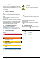
About This Manual
This symbol warns of a risk of electric shock due
to high voltage.
This manual will help you become familiar with the solar inverter.
Observe the safety regulations applicable for each country. You can
help keep the product durable and reliable during its use by handling it carefully. These are the basic requirements for optimal use
of the solar inverter.
1.1
Purpose of This Manual
This manual is part of the product. Store the manual in a safe
place.
Read the manual carefully and thoroughly and follow the instructions contained therein. This manual contains important information on the installation, commissioning and operation of the solar
inverter.
Observe this information for safe use (see “3 General Safety
Instructions”, p. 9).
This symbol is a warning of general hazards.
1.4
Conventions Used in This Document
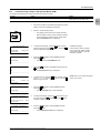
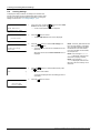
1.4.1
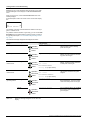
Order of Instructions
Numbered instructions must be performed in the specified order.
1.
Step
→
When the solar inverter reacts to a step, this reaction is
marked with an arrow.
2.
Step
The installer and the operator must have access to this manual and
must be familiar with the safety instructions.
3.
Step
The solar inverter can be safely and normally operated if installed
and used in accordance with this manual. Delta Energy Systems is
not responsible for damage incurred by failure to comply with the
installation and operating instructions in this manual.
þ
1.2
1.4.2
Target audience of this manual
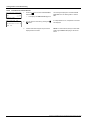
The end of instructions is designated as follows:
End of instructions
Instructions consisting of only one step are shown as follows:
►
Step
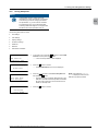
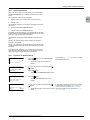
User buttons and LEDs
This manual is aimed at qualified electricians.
User buttons and LEDs are shown in this document as follows:
Only Chapters “9 Production Information”, p. 50 and “12 Diagnostics and Troubleshooting”, p. 69 pertain to the user. All other
activities may only be performed by qualified electricians.
User buttons on solar inverter: ESC button.
1.3
Warnings and Symbols
LEDs on solar inverter: Failure LED
LED symbol
The following section explains the warnings and symbols used in
this manual.
LED flashes.
DAnGER
LED is off.
Indicates an extremely hazardous situation. An accident
will result in death or serious injury.
1.4.3
WARnInG
Indicates a very hazardous situation. An accident can
result in death or serious injury.
CAUTIOn
Indicates a hazardous situation. An accident can result in
mild to moderate injury.
Meaning
LED stays on.
Information on Display
Information shown on the solar inverter display includes menus,
settings and messages.
This information is shown in this manual as follows:
Menu names: User settings menu
Parameter names: Cos phi parameter.
ATTEnTIOn
Indicates a hazardous situation that can result in property
damage.
nOTE
Contains general information on using the solar inverter. A
note does not indicate hazardous situations.
6
Operation and Installation Manual for SOLIVIA 2.0/2.5/3.0/3.3/3.6/5.0 EU G4 TR
2. Intended purpose
2.
Intended purpose
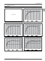
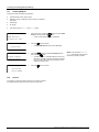
This EU-series solar inverter may be used in the following countries:
nOTE
EN
This list may change due to ongoing certification
processes. If you have any questions, please
contact the Delta Support Team.
Country
Belgium
Bulgaria
Czech Republic
Denmark
France
Germany
Great Britain
Standard
Synergrid C10/11 2012
VDE 0126
Netherlands
Poland
Portugal
Romania
VDE AR 4105
French islands 60 Hz, UTE 15 712-1
VDE AR 4105
G59-2 230 V + 240 V
G83-1
Greece/islands, Greece/continent
CEI 0-21:2012.06 for PV systems ≤ 6 kW
CEI 0-21:2012.06 for PV systems > 6 kW
VDE 0126 + EN 50438
EN 50438
EN 50438
VDE 0126
Slovakia
Spain
VDE 0126
Spanish islands, RD661, RD1699
Greece
Italy
2.0
x
x
x
x
x
x
2.5
x
x
x
x
x
x
x
x
x
x
x
x
SOLIVIA
3.0
3.3
x
x
x
x
x
x
x
x
x
x
x
x
x
x
x
x
x
x
x
x
x
x
x
x
3.6
x
x
x
x
x
x
x
x
x
x
x
x
5.0
x
x
x
x
x
x
x
x
x
x
x
x
x
x
x
x
x
x
x
x
x
x
x
x
x
x
x
x
x
x
The solar inverter may only be used as intended.
Proper use of the solar inverter meets the following criteria:
●
Use in stationary PV systems connected to the local power
grid for converting the direct current in the PV system to alternating current and feeding it into the grid
●
Use within the specified power range (see “15 Technical Specifications”, p. 80) and under the specified ambient conditions
(indoor area or covered outdoor area with up to IP65)
Any of the following uses of the solar inverter is considered
improper:
●
Isolated operation The solar inverter has anti-islanding and
other monitoring features.
●
Use in mobile PV systems.
Operation and Installation Manual for SOLIVIA 2.0/2.5/3.0/3.3/3.6/5.0 EU G4 TR
7
2. Intended purpose
8
Operation and Installation Manual for SOLIVIA 2.0/2.5/3.0/3.3/3.6/5.0 EU G4 TR
3. General Safety Instructions
3.
General Safety Instructions
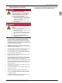
DAnGER
●
All connections must be sufficiently insulated in order to comply with the IP65 protection rating. Unused connections must
be closed by placing cover caps on the solar inverter.
Risk of death by electrocution
Potentially fatal voltage is applied to the solar
inverter during operation. This potentially fatal
voltage is still present for five minutes after all
power sources have been disconnected.
► Never open the solar inverter.
► Always disconnect the solar inverter from
power before installation, open the DC isolating switch and make sure neither can be
accidentally reconnected.
► Wait at least five minutes until the capacitors
have discharged.
EN
DAnGER
Risk of death or serious injury from electrocution
Potentially fatal voltage may be applied to the DC
connections of the solar inverter.
► Never disconnect the PV modules when the
solar inverter is powered.
► First switch off the grid connection so that
the solar inverter cannot feed energy into the
grid.
► Then open the DC isolating switch.
► Make sure the DC connections cannot be
accidentally touched.
●
The solar inverter can be safely and normally operated if
installed and used in accordance with this manual (see
IEC 62109-5.3.3). Delta Energy Systems is not responsible
for damage incurred by failure to observe the installation and
operating instructions in this manual. For this reason, be sure
to observe and follow all instructions!
●
Installation and commissioning may only be performed by
qualified electricians using the installation and commissioning
instructions found in this manual.
●
The solar inverter must be disconnected from power and the
PV modules before any work on it can be performed.
●
The solar inverter has a high leakage current value (see
“15 Technical Specifications”, p. 80). The ground wire must
be connected before commissioning.
●
Do not remove any warning signs that the manufacturer has
installed on the solar inverter.
●
Improper handling of the solar inverter my result in physical
injury and damage to property. For this reason, observe and
follow all general safety instructions and warnings.
●
The solar inverter contains no components that must be maintained or repaired by the operator or installer. All repairs must
be performed by Delta Energy Systems. Opening the cover
will void the warranty.
●
Do not disconnect any cables when the solar inverter is powered due to risk of a fault arc.
●
To prevent lightning strikes, follow the relevant regulations applicable in your country.
●
The surface of the solar inverter can become very hot.
●
The solar inverter is very heavy (see “15 Technical Specifications”, p. 80). The solar inverter must be lifted and carried
by at least two people.
●
Only devices in compliance with SELV (EN 69050) may be
connected to the RS485 and USB interfaces.
Operation and Installation Manual for SOLIVIA 2.0/2.5/3.0/3.3/3.6/5.0 EU G4 TR
9
4. Unpacking
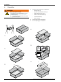
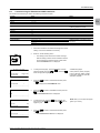
4.
Unpacking
►
WARnInG
Risk of injury due to weight
The weight of the solar inverter (see “15 Technical Specifications”, p. 80) can cause injury if
not handled properly.
► The solar inverter must be lifted and carried
by at least two people.
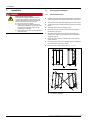
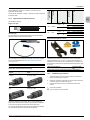
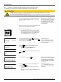
Check the scope of delivery for completeness:
–
Mounting plate (a)
–
Operation and installation manual (b)
–
Wieland RST25i3S AC plug (c)
–
2 M6 nuts and 2 M6 washers (d)
–
"Power limit" label (e)
–
Solar inverter (f)
►
Check all parts for signs of damage!
►
Store the packaging in a safe place!
➃
➀
➄
(b)
(c)
(d)
➁
(e)
➅
➂
10
(f)
(a)
Operation and Installation Manual for SOLIVIA 2.0/2.5/3.0/3.3/3.6/5.0 EU G4 TR
5. Product Description
5.
Product Description
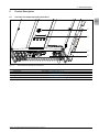
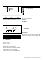
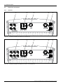
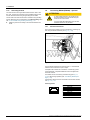
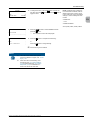
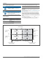
5.1
Overview of Components and Connections
EN
➀
➁
➂
➃
Fig. 5.1:
Solar Inverter Components and Connections
no.
Component/Connection
Description
➀
➁
➂
➃
Status LEDs
See Chapter “5.3 Status LEDs”, p. 14
Display and Buttons
See Chapter “5.4 Display and Buttons”, p. 14
Type Plate
See Chapter “5.2 Type Plate”, p. 12
Electrical Connections
See Chapter “5.5 Electrical Connections”, p. 18
Operation and Installation Manual for SOLIVIA 2.0/2.5/3.0/3.3/3.6/5.0 EU G4 TR
11
5. Product Description
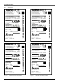
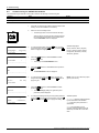
Type Plate
VDE 0126-1-1 (D)
VDE-AR-N-4105
Country specific standards and settings:
see manual
IP class:
IP65
Safety class: 1
5min.
Ambient temp: -25°C...+70°C, derating >55°C
SOLIVIA2.0EUG4TR
EOE45010459
XX
YYWW
LLLMMMXXYYWWZZZZZZ
www.solar-inverter.com
Designed in: Germany
Made in:
production plant
Fig. 5.2:
SOLIVIA 2.0 EU G4 TR type plate
Country specific standards and settings:
see manual
IP class:
IP65
Safety class: 1
5min.
Ambient temp: -25°C...+70°C, derating >55°C
SOLIVIA3.0EUG4
EOE46010287
Rev:
Date code:
S/N:
XX
YYWW
LLLMMMXXYYWWZZZZZZ
www.solar-inverter.com
Designed in: Germany
Made in:
production plant
Fig. 5.4:
12
SOLIVIA 3.0 EU G4 TR type plate
Country specific standards and settings:
see manual
IP class:
IP65
Safety class: 1
5min.
Ambient temp: -25°C...+70°C, derating >55°C
SOLIVIA2.5EUG4
EOE46010288
Rev:
Date code:
S/N:
XX
YYWW
LLLMMMXXYYWWZZZZZZ
www.solar-inverter.com
Designed in: Germany
Made in:
production plant
SOLIVIA 2.5 EU G4 TR type plate
DC operating volt. range:
125-600V
DC operating volt. range (MPP): 150-480V
DC max. input voltage:
600V
DC max. operating current:
24.0A
DC max. current per string:
17A
SN: LLLMMMXXYYWWZZZZZZ
VDE 0126-1-1 (D)
VDE-AR-N-4105
VDE 0126-1-1 (D)
VDE-AR-N-4105
Fig. 5.3:
125-600V
DC operating volt. range:
DC operating volt. range (MPP): 150-480V
600V
DC max. input voltage:
22.0A
DC max. operating current:
17A
DC max. current per string:
AC nom.output voltage:
230V
AC nom.output frequency:
50Hz
AC max. continuous output current:
15.5A
AC max. continuous output power:
3000VA
AC power factor:
Cap 0.8~Ind 0.8
230V
AC nom.output voltage:
50Hz
AC nom.output frequency:
15.5A
AC max. continuous output current:
2500VA
AC max. continuous output power:
Cap 0.8~Ind 0.8
AC power factor
SN: LLLMMMXXYYWWZZZZZZ
230V
AC nom. output voltage:
50Hz
AC nom. output frequency:
11.0A
AC max. continuous output current:
2000VA
AC max. continuous output power:
Cap 0.8~Ind 0.8
AC power factor
Rev:
Date code:
S/N:
125-600V
DC operating volt. range:
DC operating volt. range (MPP): 150-480V
600V
DC max. input voltage:
18.2A
DC max. operating current:
17A
DC max. current per string:
125-600V
150-480V
600V
15A
17A
AC nom.output voltage:
230V
AC nom.output frequency:
50Hz
AC max. continuous output current:
15.5A
AC max. continuous output power:
3300VA
AC power factor:
Cap 0.8~Ind 0.8
VDE 0126-1-1 (D)
VDE-AR-N-4105
Country specific standards and settings:
see manual
IP class:
IP65
Safety class: 1
5min.
Ambient temp: -25°C...+70°C, derating >55°C
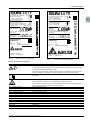
SOLIVIA3.3EUG4TR
EOE46010252
Rev:
Date code:
S/N:
XX
YYWW
LLLMMMXXYYWWZZZZZZ
www.solar-inverter.com
Designed in: Germany
Made in:
production plant
Fig. 5.5:
SN: LLLMMMXXYYWWZZZZZZ
DC operating volt. range:
DC operating volt. range (MPP):
DC max. input voltage:
DC max. operating current:
DC max. current per string:
SN: LLLMMMXXYYWWZZZZZZ
5.2
SOLIVIA 3.3 EU G4 TR type plate
Operation and Installation Manual for SOLIVIA 2.0/2.5/3.0/3.3/3.6/5.0 EU G4 TR
5. Product Description
DC operating volt. range (MPP):
DC max. input voltage:
DC max. operating current:
DC max. current per string:
230V
AC nom.output voltage:
50Hz
AC nom.output frequency:
16.0A
AC max. continuous output current:
3600VA
AC max. continuous output power:
Cap 0.8~Ind 0.8
AC power factor
AC nom.output voltage:
AC nom.output frequency:
AC max. output current:
AC nom. output power:
150-480V
600V
37A
18A
230 220V
50 60Hz
27.2 28.5A
5000W
Country specific standards and settings:
see manual
IEC 60950-1
EN 50178
IEC 62103
IEC 62109-1 and IEC 62109-2
Country specific standards and settings:
see manual
IP class:
IP65
Safety class: 1
Ambient temp: -25°C...+70°C, derating >55°C
IP class:
IP65
Safety class: 1
5min
Ambient temp: -20°C...+70°C, derating >55°C
SOLIVIA3.6EUG4
EOE46010316
SOLIVIA5.0EUG4TR
EOE46010253
Rev:
Date code:
S/N:
Rev:
Date code:
S/N:
VDE 0126-1-1(D)
VDE-AR-N-4105
XX
YYWW
LLLMMMXXYYWWZZZZZZ
XX
YYWW
LLLMMMXXYYWWZZZZZZ
www.solar-inverter.com
www.solar-inverter.com
Designed in: Germany
Made in:
production plant
Designed in: Germany
Made in:
production plant
Fig. 5.6:
SOLIVIA 3.6 EU G4 TR type plate
Fig. 5.7:
EN
SN: LLLMMMXXYYWWZZZZZZ
DC operating volt. range:
125-600V
DC operating volt. range (MPP): 170-480V
DC max. input voltage:
600V
DC max. operating current:
22.0A
DC max. current per string:
17A
SOLIVIA 5.0 EU G4 TR type plate
Meaning of Information on Type Plate
Warning Symbols on Type Plate
5 min
Meaning of Warning Symbols
Risk of death by electrocution
Potentially fatal voltage is present when the solar inverter is in operation that remains for five
minutes after being disconnected from power.
Never open the solar inverter. The solar inverter contains no components that must be maintained or repaired by the operator or installer. Opening the cover will void the warranty.
Read the manual before working with the solar inverter and follow the instructions contained in
the manual.
Risk of injury from high temperatures
When in operation, the housing of the solar inverter can become very hot.
DC operating volt. range
DC operating volt. range (MPP)
DC max. input voltage
DC max. operating current
DC max. current per string
AC nom. output voltage
AC nom. output frequency
AC max. continuous output current
AC max. continuous output power
AC power factor
IP class
Safety class
Ambient temperature/derating
Only touch the housing of the solar inverter (outside of the control panel) with safety gloves.
The control panel itself is protected by a special surface.
DC operating volt. range
DC operating volt. range (MPP)
DC max. input voltage
DC max. operating current
DC max. current per string
AC nom. output voltage
AC nom. output frequency
AC max. continuous output current
AC max. apparent power
AC power factor (cos φ)
IP class
Safety class
Ambient temperature/derating
Operation and Installation Manual for SOLIVIA 2.0/2.5/3.0/3.3/3.6/5.0 EU G4 TR
13
5. Product Description
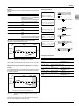
5.3
Status LEDs
Use
●
Exit current menu.
ESC
Operation
Earth Fault
Failure
Status LEDs
no. Label
➀
➁
➂
Buttons
Symbol
➀
➁
➂
Fig. 5.8:
5.4.3
Designation
Color
OperatiOn
Operation
Green
earth Fault
Earth fault
Red
Failure
Failure
Yellow
Information on the LED messages can be found in “12 Diagnostics
and Troubleshooting”, p. 69.
5.4.4
●
●
Cancel value setting.
Move upwards in menu.
●
●
Set value (increase)
Move downwards in menu.
●
●
Set a value (decrease).
Select menu item.
●
Open configurable value for editing.
●
Finish editing (adopt set value).
General Menu Structure
The menus have up to three levels:
[Main menu]
...
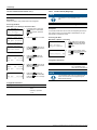
5.4
Display and Buttons
5.4.1
Overview
300 USB features
400 Production Info
410 Current Data
411 Current Overview
412 Current Data AC
➀
ESC
...
420 Day Statistics
➁
430 Week Statistics
...
500 User Settings
Fig. 5.9:
Overview of Display and Buttons
no.
Designation
➀
➁
Display
...
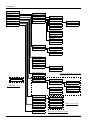
Most menu names consist of a three-digit number and a menu title.
An overview of the complete menu structure can be found in Chapter “16.2 Overview of Menu Structure”, p. 83.
Control Buttons
5.4.2
Display Layout
-0
--I
-n
-s
-t
-a
-l
-l
--s
-e
-t
-t
-i
-n
-g
-s
10
Language:
English
➔Date and time
Display settings
Fig. 5.10:
Display
The display has four rows of 20 characters each.
The first row contains the name and number of the currently displayed menu.
The second to fourth rows show the menu elements.
A small arrow in the third row shows the currently selected menu
item.
14
Operation and Installation Manual for SOLIVIA 2.0/2.5/3.0/3.3/3.6/5.0 EU G4 TR
5. Product Description
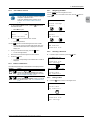
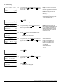
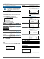
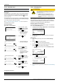
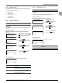
5.4.5
"Go to Menu" function
5.4.7
Use the
nOTE
You can use the "Go to Menu" function to directly
navigate to a particular menu.
A list of the available menu numbers can be
found in “16.2 Overview of Menu Structure”,
p. 83.
1.
To start the Go to Menu function, press the ESC button for at
least three seconds.
→
Press the
3.
buttons to set the first digit of the menu number.
You can only set menu numbers that actually exist. The
name of the associated menu is displayed in the fourth
display row.
Once you have set the first digit, press the
→
button.
The second digit flashes.
4.
Enter the second and third digit in the same manner.
5.
Press the
→
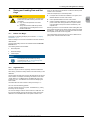
5.4.6
EN
SOLIVIA ##
------------------➔Install settings
Options
button to enter the menu number.
The first digit flashes.
Use the
→
button to
----S
-O
-L
-I
-V
-I
-A
--#
-#
-----Install settings
➔Options
USB features
➔Menu:
411
411 Current data
→
buttons to navigate in a menu.
button to move down in the menu, and the
Go to Menu opens.
Go to menu
2.
Use the
move up.
navigating the Menu
button.
The menu corresponding to the entered menu number is
displayed.
Button combinations
------------------InstS
aO
lL
lIV
sI
eA
tt#
i#
ngs
Options
➔USB features
Production info
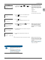
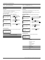
5.4.8
►
Selecting a Submenu
In order to open a submenu, press the
button.
Install settings
OptiS
oO
nL
sIVIA ##
USB features
➔Production info
User settings
The table lists special button combinations for the display buttons.
Buttons
ESC
Action
Pressing the ESC and
buttons at the same time
displays the 100 Install Settings menu where
you can change the display language to be used,
see “10.2 Display language”, p. 52.
Pressing the
buttons at the same time
displays 800 Standard Menu, where you can set
the "standard menu", see “10.14 Standard menu”,
p. 62.
400 Production info
------------------➔Current data
Day statistics
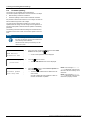
5.4.9
►
Exiting a Menu
Press the ESC button to return to the higher menu.
400 Production info
------------------➔Current data
Day statistics
ESC
Install settings
OptiS
oO
nL
sIVIA ##
USB features
➔Production info
User settings
Operation and Installation Manual for SOLIVIA 2.0/2.5/3.0/3.3/3.6/5.0 EU G4 TR
15
5. Product Description
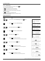
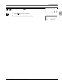
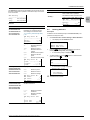
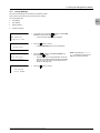
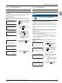
5.4.10
Setting Values
You can set various parameters on the display. Use the
tons to change the parameter values.
The
button increases the value of the parameter.
The
button decreases the value of the parameter.
but-
The ESC button can be used to cancel the setting, and the original
value is then displayed.
The
button applies the new parameter value.
The example on the next page illustrates the procedure for changing the value of a parameter.
Example: Setting the date
Buttons
ESC
Action
Result
1.
Press the ESC button until the main menu is displayed.
2.
In the main menu, select Install Settings using the
3.
Press the
4.
Select Date and Time using the
5.
Press the
6.
Select Date using the
7.
Press the
→
button to open 100 Install Settings.
Press the
110 Date and time
------------------➔Date:
25.05.2012
Time:
14:26:51
buttons.
110 Date and time
------------------➔Date:
25.05.2012
Time:
14:26:51
buttons.
The digits for the second value (in this case the day) flash.
11. Press the
110 Date and time
------------------➔Date:
25.05.2012
Time:
14:26:51
110 Date and time
------------------➔Date:
12.05.2012
Time:
14:26:51
button to apply the new value.
10. Select the day using the
16
-0
--I
-n
-s
-t
-a
-l
-l
--s
-e
-t
-t
-i
-n
-g
-s
10
Language:
English
➔Date and time
Display settings
The digits for the first value (in this case the month) will flash.
9.
→
buttons.
button to begin configuration.
Select the month using the
SOLIVIA ##
------------------➔Install settings
Options
100 Install settings
------------------➔Language:
English
Date and time
button to open 110 Date and Time.
8.
→
buttons.
buttons.
110 Date and time
------------------➔Date:
12.05.2012
Time:
14:26:51
110 Date and time
------------------➔Date:
12.01.2012
Time:
14:26:51
button to apply the new value.
The digits for the last value (in this case the year) flash.
110 Date and time
------------------➔Date:
12.01.2012
Time:
14:26:51
Operation and Installation Manual for SOLIVIA 2.0/2.5/3.0/3.3/3.6/5.0 EU G4 TR
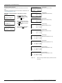
5. Product Description
Buttons
Action
Result
12. Select the year using the
13. Press the
þ
buttons.
110 Date and time
------------------➔Date:
12.01.2013
Time:
14:26:51
button to apply the new value.
The value is adopted and the editing mode is exited.
Operation and Installation Manual for SOLIVIA 2.0/2.5/3.0/3.3/3.6/5.0 EU G4 TR
110 Date and time
------------------➔Date:
12.01.2013
Time:
14:26:51
17
EN
5. Product Description
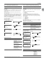
5.5
Electrical Connections
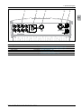
5.5.1
Overview
➀
Fig. 5.11:
➁
18
➃
➄
➂
➃
➄
Electrical Connections for SOLIVIA 2.0, 2.5 EU G4 TR
➀
Fig. 5.12:
➂
➁
Electrical Connections for SOLIVIA 2.0, 2.5, 3.0, 3.3, 3.6 EU G4 TR
Operation and Installation Manual for SOLIVIA 2.0/2.5/3.0/3.3/3.6/5.0 EU G4 TR
5. Product Description
➀
➁
➂
➃
➄
EN
Fig. 5.13:
Electrical Connections for SOLIVIA 5.0 EU G4 TR
no. Designation
➀
➁
➂
➃
➄
Description
DC connections
See Chapter “5.5.2 DC connections and DC isolating switch”, p. 20
DC isolating switch
See Chapter “5.5.2 DC connections and DC isolating switch”, p. 20
USB interface
See Chapter “5.5.5 USB interface”, p. 20
AC connection
See Chapter “5.5.3 AC connection”, p. 20
RS485 interfaces
See Chapter “5.5.4 RS485 interface (EIA485)”, p. 20
Operation and Installation Manual for SOLIVIA 2.0/2.5/3.0/3.3/3.6/5.0 EU G4 TR
19
5. Product Description
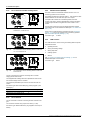
5.5.2
DC connections and DC isolating switch
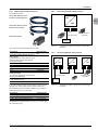
5.5.4
RS485 interface (EIA485)
The solar inverter has two RS485 interfaces to which a PC or a
monitoring system can be connected.
The RS485 interfaces are internally wired 1:1. This means that both
RS485 interfaces can be used as an input or an output.
If multiple solar inverters are connected together, each solar
inverter must have a unique ID (identification number). Monitoring
systems require the ID to recognize each solar inverter in a PV
system.
Fig. 5.14:
DC connections and DC isolating switch for
SOLIVIA 2.0, 2.5 EU G4 TR
The last solar inverter must have an RS485 termination resistor
connected, which can be ordered from Delta (see “16.1 Order numbers”, p. 82).
The ID can be configured during commissioning (see “8 Commissioning”, p. 34) and can be changed at any time during operation
(see “10.6 RS485 (EIA485) Settings”, p. 54).
Connection type:
5.5.5
2 x RJ45
USB interface
The USB interface is used for saving and loading data and reports.
Supported functions:
Fig. 5.15:
DC connections and DC isolating switch for SOLIVIA
3.0, 3.3, 3.6 EU G4 TR
●
Updating firmware
●
Saving and loading settings
●
Saving swap data
●
Creating reports
●
Service
See “11 Saving and Loading Data and Settings”, p. 63 for a
detailed description of the functions.
Connection type:
Fig. 5.16:
USB A
DC connections and DC isolating switch for SOLIVIA
5.0 EU G4 TR
The DC connections are used for connecting the PV module
string(s) to the solar inverter.
The integrated DC isolating switch can separate the solar inverter
from the DC voltage of the PV modules.
The maximum permissible input current is 29 A for each DC connection.
Connection type: Multi-contact MC4 plug, paired plug (DC+) and
socket (DC-)
Solar Inverter
SOLIVIA 2.0, 2.5 EU G4 TR
SOLIVIA 3.0, 3.3, 3.6 EU G4 TR
SOLIVIA 5.0 EU G4 TR
5.5.3
number of DC inputs
2
3
4
AC connection
The AC connection is used for connecting the solar inverter to the
grid.
The connection is made using a triple-core cable (L, N, PE).
Connection type: Wieland RST25i3s, plug supplied in the scope of
delivery.
20
Operation and Installation Manual for SOLIVIA 2.0/2.5/3.0/3.3/3.6/5.0 EU G4 TR
6. Operating Behavior
6.
6.1
Operating Behavior
General Principle of Operation
The solar inverter converts DC electricity into AC electricity, which
is then fed into the local power grid.
MPP Tracking
The solar inverter has an MPP tracker. The MPP (Maximum Power
Point) tracker is an automatic function that searches in regular
intervals for the operating point with the highest possible power.
On the normal setting, the MPP tracker searches the DC input voltage range near the current operating point. If a higher power point
is found, the solar inverter sets this as the new operating point.
The manual "Shadowing" function can be used to set the MPP
tracker to scan over a wider DC voltage range. This MPP tracking
function is especially useful when small shadows regularly pass
over the PV modules, e.g., from chimneys or trees. In order to
adapt the function to local conditions as precisely as possible, the
extended MPP tracking can be configured in three stages.
Electrical Isolation
The AC and DC sides of the solar inverter are electrically isolated
by a high frequency transformer. This makes it impossible for DC
electricity to reach the AC side of the inverter.
Anti-Islanding
The integrated anti-islanding device switches off the solar inverter
when the grid fails.
Temperature Control
The convection cooling system provides optimal heat dissipation.
An internal temperature controller reduces the output power at
ambient temperatures in the upper operating range. The higher the
operating temperature, the greater the power reduction. It is possible for the power reduction to be adjusted to 0 kW.
6.2
Impact of DC Input Voltage
The DC input voltage values mentioned in this section can be found
in Chapter “15 Technical Specifications”, p. 80.
The maximum input voltage must never be exceeded. Measure
the input voltage and use an overvoltage protection device on the
DC side to prevent higher voltages from reaching the inverter. The
maximum open-circuit voltage occurs at the lowest assumed temperature. More exact information on temperature dependency is
provided in the PV module data sheet.
6.4
Functions Affecting Operating Behavior
The solar inverter offers various functions for affecting operating
behavior:
●
Active power control
●
Reactive power control
●
Insulation and grounding monitoring
●
Extended MPP tracking in the case of partial shadowing of the
PV modules
EN
The availability of individual functions depends on the configured
grid.
A detailed description of the functions is provided in Chapter
“10 Settings”, p. 52.
6.5
Balancing Asymmetrical Grid Loads
When using single-phase power inverters in a three-phase grid, an
asymmetric phase failure can lead to unreliable grid load.
In some countries, there are specific limits for the grid load, for
example, in Germany this is max. 4.6 kVA between two phases.
If an unreliable grid load can occur during installation, single-phase
solar inverters can only be operated in these countries when a
SOLIVIA Gateway M1 G2 is installed as well.
The Gateway controls the feed-in so that an impermissible grid load
cannot occur during an asymmetric phase failure.
The asymmetrical grid load balancing can be activated during the
initial commissioning.
After completion of initial commissioning, the function can only be
changed using a PIN.
A detailed description of this function can be found in Chapter
“7.1 Planning the Installation”, p. 24.
6.6
Data Analysis and Communication
The solar inverter has a comprehensive system for recording operating behavior.
The log can be viewed directly on the display. It is also possible
to view the log on a computer using the communication interface
(RS485).
Connecting a SOLIVIA Gateway M1 G2 to the solar inverter allows
this information to be accessed worldwide via the Internet.
All information can be saved to a USB drive to be used later.
The feed-in voltage range of the solar inverter defines the range
of input voltages over which the solar inverter will feed electricity
into the grid.
The following information and data are logged:
The MPP input voltage range of the solar inverter defines the
range of input voltages over which the MPP tracker is activated.
The most important production information is recorded in statistics
for day, week, month, year and total runtime. There are also special
statistics for the last seven days the solar inverter was in operation.
6.3
All production information is backed up to a separate hard drive
monthly.
ConfiguringPermanentActiveandReactive Power Reduction
The settings for reduction of active power and/or reactive power
can be configured during initial commissioning. After completion of
initial commissioning the values can only be changed using a PIN.
Operation and Installation Manual for SOLIVIA 2.0/2.5/3.0/3.3/3.6/5.0 EU G4 TR
Production Information
ConfigurationSettings
The configuration settings of the solar inverter can be exchanged
between solar inverters of the same type by using a USB drive.
This above all makes switching solar inverters easier.
21
6. Operating Behavior
Warning and Error Messages
Every warning or error message is stored in the solar inverter with
a time stamp. The messages are stored in the event log or in the
internal log, depending on the cause of the error.
The event log is primarily intended for the installer and should make
analyzing and resolving problems easier.
The internal log helps Delta Solar Support when analyzing more
difficult problems.
Reports
The reports combine the various information on production, events,
settings, parameter changes and errors.
For LVD grids, the last five failures are stored together with the
settings.
22
Operation and Installation Manual for SOLIVIA 2.0/2.5/3.0/3.3/3.6/5.0 EU G4 TR
6. Operating Behavior
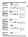
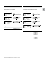
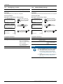
6.7
Characteristic Curves
EfficiencyCurves
SOLIVIA 2.0 EU G4 TR
SOLIVIA 2.5 EU G4 TR
Efficiency [%]
EN
98
96
94
92
90
not yet available
88
86
84
82
80
1000
500
0
1500
2000
2500
Power [W]
150 V
SOLIVIA 3.0 EU G4 TR
Efficiency [%]
98
98
96
96
94
94
92
92
90
90
88
88
86
86
84
84
82
82
0
480 V
SOLIVIA 3.3 EU G4 TR
Efficiency [%]
80
360 V
500
1000
1500
2000
2500
3000
80
500
0
1000
1500
2000
2500
3000 3300
Power [W]
150 V
360 V
Power [W]
480 V
150 V
SOLIVIA 3.6 EU G4 TR
Efficiency [%]
98
98
96
96
94
94
92
92
90
90
88
88
86
86
84
84
82
82
0
480 V
SOLIVIA 5.0 EU G4 TR
Efficiency [%]
80
360 V
500
1000
1500
2000
2500
3000
3600
80
0
1000
2000
3000
4000
150 V
360 V
480 V
Operation and Installation Manual for SOLIVIA 2.0/2.5/3.0/3.3/3.6/5.0 EU G4 TR
5000
Power [W]
Power [W]
150 V
300 V
480 V
23
7. Installation
7.
Installation
DAnGER
Risk of death by electrocution
Potentially fatal voltage is applied to the solar
inverter during operation. This potentially fatal
voltage is still present for five minutes after all
power sources have been disconnected.
► Never open the solar inverter.
► Always disconnect the solar inverter from
power before installation, open the DC isolating switch and make sure neither can be
accidentally reconnected.
► Wait at least five minutes until the capacitors
have discharged.
7.1
Planning the Installation
7.1.1
General Instructions
►
Possible noise emissions can be disruptive when the device is
used in living areas. Avoid installing the device in living areas.
►
Always use the mounting plate supplied with the solar inverter.
►
Check that the wall is capable of bearing the heavy load of the
device.
►
Mount the solar inverter on a fireproof wall.
►
First mount the solar inverter on the wall and then establish
the electrical connections.
►
Mount the solar inverter so that the LEDs and display can
be easily seen. Make sure the reading angle and installation
height are sufficient.
►
Mount the solar inverter on a vibration-free wall to avoid disruptive vibrations.
►
Use dowels and screws for the installation that are suitable for
the wall material and the heavy weight.
►
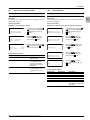
Mount the solar inverter vertically, see Fig. 7.1, p. 24.
✓
Fig. 7.1: Mounting Alignment
24
Operation and Installation Manual for SOLIVIA 2.0/2.5/3.0/3.3/3.6/5.0 EU G4 TR
7. Installation
7.1.2
Ambient Conditions
7.1.3
Consideration of Asymmetrical Grid Load
►
The solar inverter has an IP65 degree of protection and can be
installed indoors or in protected outdoor areas.
The use of a SOLIVIA Gateway M1 G2 is mandatory for some
installation types.
►
Note the operating temperature range at full power without
derating and the maximum operating temperature range.
This applies, for example, to installations where several singlephase solar inverters feed into the same phase and an impermissible asymmetrical grid load can occur if a phase fails.
When the first operating temperature range is exceeded, the
solar inverter reduces the amount of power generated.
–
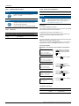
Be sure to observe the specified minimum clearances to
walls and other solar inverters when installing the device
(see Fig. 7.2, p. 25).
Do not install two solar inverters directly above one
another.
–
Avoid direct sunlight.
–
Ensure adequate air circulation. Hot air must be able to
dissipate upward. For this reason, installation directly
under a closed roof is not recommended.
>50 cm
–
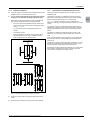
Fig. 7.3, p. 26 shows an example of such an installation for
Germany. In Germany, the asymmetrical grid load may not exceed
4.6 kW.
The SOLIVIA 11 EU G4 TR three-phase solar inverter does not
experience this problem, because it controls the feed-in internally
and always distributes the fed-in power evenly among all three
phases.
The situation is different for single-phase solar inverters. If the
phase fails, an asymmetrical grid load greater than 4.6 kW can
occur.
In this case, the Gateway controls the feed-in via the RS485 interface and ensures that an impermissible asymmetrical grid load
cannot occur.
If a Gateway is used to balance asymmetrical grid loads, you must
activate the "asymmetrical grid load balancing" function on each
single-phase solar inverter during initial commissioning.
>10 cm
If the RS485 connection between the Gateway and a single-phase
solar inverter is interrupted, the function switches off the solar
inverter after a specified time for safety reasons.
>50 cm
>10 cm
EN
>10 cm
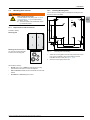
Fig. 7.2: Mounting Clearances for Proper Convection
►
Avoid heavy soiling. Dust can impair the performance of the
device.
►
Protect the solar inverter from heavy rain and snow deposits.
Operation and Installation Manual for SOLIVIA 2.0/2.5/3.0/3.3/3.6/5.0 EU G4 TR
25
7. Installation
–
Termination
resistor
~
SOLIVIA 5.0 TR
L
kWh
N PE
–
~
–
~
SOLIVIA 3.6 TR SOLIVIA 3.6 TR
L
N PE
L
kWh
N PE
–
~
SOLIVIA 11 TR
L1 L2 L3
SOLIVIA
Gateway
M1 G2
N PE
kWh
L1
L2
L3
N
PE
Fig. 7.3:
26
Example: Multiple solar inverters connected together
Operation and Installation Manual for SOLIVIA 2.0/2.5/3.0/3.3/3.6/5.0 EU G4 TR
7. Installation
WARnInG
7.2.2
Installing Mounting Plate
You can use the mounting plate as a template for marking the positions of the holes to be drilled.
Risk of injury due to weight
The solar inverter is very heavy (see “15 Technical Specifications”, p. 80). Incorrect handling
can lead to injuries.
► The solar inverter must be lifted and carried
by at least two people.
A
B
∅
Included in delivery:
320
Required Tools and Accessories
200
7.2.1
EN
A
6,5
12
Mounting Solar Inverter
12
7.2
Mounting plate
12
38
A
C
B
90
B
A
150
319,5
C
410 ± 0,5
Mounting nuts and washers: 2
pcs. each for mounting the solar
inverter to the mounting plate
Fig. 7.4:
Mounting plate scale drawing
1.
Attach the mounting plate to the wall using at least four screws
(avg. 6 mm) and dowels. Use the four holes A or the four
holes B for the four screws (see Fig. 7.4, p. 27).
2.
Screw the screws tightly into the wall.
Not included in delivery:
▪
Screws (avg. 6 mm) + dowels for attaching the mounting
plate to the wall. At least four screws are required.
▪
Drill and drill bits suitable for the wall material and size of the
dowels.
▪
Screwdriver or wrench fitting the screws.
Operation and Installation Manual for SOLIVIA 2.0/2.5/3.0/3.3/3.6/5.0 EU G4 TR
27
7. Installation
7.2.3
1.
Mounting Solar Inverter
7.3
Attach the solar power inverter to the mounting plate, see Fig.
7.5, p. 28.
Grid Connection
DAnGER
Danger of death or severe injuries from dangerous voltage
► Disconnect the AC conductor from power
before removing or inserting the AC plug.
7.3.1
General Instructions
The solar power inverter is connected to the local power grid with
an AC connection, see Fig. 7.6, p. 28.
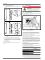
Fig. 7.6:
Location of AC connection
The round AC plug has a coupling to protect against accidental
removal. This coupling can be disengaged with a screwdriver.
Use a flexible triple-core cable (L, N, PE) with a conductor crosssection from 2.5 to 4.0 mm² (coefficient k=1).
Fig. 7.5: Attaching the solar power inverter to the mounting
plate
2.
Secure the solar power inverter to the mounting plate by
fitting the washers and mounting nuts on the stud bolts and
then tightening (see Fig. 7.4, p. 27, item C). (The stud bolts
are also used for connecting the grounding cable to the solar
power inverter.)
3.
Check the installation.
þ
Physical installation of the solar power inverter is now complete.
Observe the required grid impedance at the grid connection point
(cable length, conductor cross-section).
Select the cable length and conductor cross-section so that the
conductor temperature and cable losses are as small as possible.
In some countries (e.g. France and Germany), specific requirements must be met for system installation (UTE C15-712-1, VDE
0100 712). These requirements specify the minimum cable crosssection and the protective measures required to prevent overheating due to high currents. Always adhere to the specific requirements of your country.
The energy meter must be installed between the solar power
inverter and the grid feed-in point. Observe the directives of your
local electricity supplier when doing this.
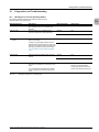
The following table shows the maximum permissible trigger current
for the automatic circuit breaker (type B).
Solar inverter
SOLIVIA 2.0 EU G4 TR
SOLIVIA 2.5 EU G4 TR
SOLIVIA 3.0 EU G4 TR
SOLIVIA 3.3 EU G4 TR
SOLIVIA 3.6 EU G4 TR
SOLIVIA 5.0 EU G4 TR
Maximum Permitted
Fuse Rating
16.0 A
20.0 A
25.0 A
The AC and DC sides of the solar inverter are electrically isolated.
This makes it impossible for DC electricity to reach the AC side of
the inverter, i.e., a type A residual current device is sufficient. We
28
Operation and Installation Manual for SOLIVIA 2.0/2.5/3.0/3.3/3.6/5.0 EU G4 TR
7. Installation
recommend using a 20 A residual current device. However, be
sure to always adhere to the specific regulations applicable in your
country.
7.3.3
1.
The typical leakage current is less than 3.5 mA.
Establishing Connection
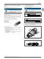
Remove the cable sheath as shown and remove 10 mm of
insulation from each wire end.
nOTE
nOTE
Observe the correct polarity of the round
plug. An incorrect configuration can destroy
the solar inverter.
The rated value of the secondary short-circuit
current at the grid connection point to the public
power grid increases due to the rated current of
the connected solar inverter.
To protect the user and the system, install the required safety and
protection devices (e.g., automatic circuit breaker and/or overvoltage protection devices).
A special kit for France is available from Delta. This kit contains all
components required to meet the requirements specified in UTE
C15-712-1 (“16.1 Order numbers”, p. 82).
7.3.2
10 mm
52,5 mm (PE: 57,5 mm)
2.
Place the end sleeves on the exposed wire ends and crimp
them on.
3.
Connect the AC cable to the AC plug as described below.
►
Unscrew the nut ➀ from the cable housing ➁ and then remove
the cable housing from the socket insert ➂.
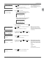
Required Tools and Accessories
Included in delivery:
Round AC plug
Wieland RST25i3S
1.
Not included in delivery:
▪
Flexible triple-core cable (L, N, PE) with a conductor crosssection from 2.5 mm2 to 4 mm2
▪
Cable end sleeves suitable for the conductor cross-section.
▪
Cable strain-relief.
▪
Locking washer for connecting the ground wire to the solar
inverter (see Fig. 7.4, p. 27, item C).
2.
➀
➁
➂
►
Slide the nut ➀ and cable housing ➁ onto the AC cable.
➁
Operation and Installation Manual for SOLIVIA 2.0/2.5/3.0/3.3/3.6/5.0 EU G4 TR
➀
29
EN
7. Installation
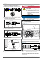
►
Insert the wires of the AC cable into the pin insert connections.
Observe the correct phase sequence when doing this.
►
Tighten the screws of the pin insert to fix the wires in place.
7.4
Connecting the PV Modules
DAnGER
Danger of death or severe injuries from dangerous voltage
Potentially fatal voltage may be applied to the DC
connections of the solar inverter.
► Never disconnect the PV modules when the
solar inverter is powered. First switch off the
grid connection so the solar inverter cannot
feed energy into the grid. Then open the DC
isolating switch.
► Make sure the DC connections cannot be
accidentally touched.
N
L
PE
N
►
L
Screw the cable housing ➁ onto the socket insert ➂ and then
screw the nut ➀ onto the cable housing.
nOTE
To ensure IP65 protection, all unused connections and interfaces must be closed using the
covers on the solar inverter.
1.
2.
7.4.1
General Instructions
The strings of the PV modules are connected to the DC connections, see Fig. 7.7, p. 30.
➂
►
➁
➀
Insert the AC plug into the AC socket ➃ on the solar inverter
until the AC plug locks into place.
➃
4.
Ground the mounting plate.
Fig. 7.7:
Location of DC connections
The negative DC pole of the string is connected to the DC-MINUS
connection; the positive DC pole to the DC-PLUS connection, see
Fig. 7.8, p. 30.
–
+
5.
Check the installation.
þ
The grid connection has been established.
Fig. 7.8:
Connecting PV modules to DC connections
The maximum input voltage of the solar inverter is 600 V when
feeding the grid. The maximum permitted current load at each DC
connection is 29 A.
30
Operation and Installation Manual for SOLIVIA 2.0/2.5/3.0/3.3/3.6/5.0 EU G4 TR
Not included in delivery:
Single-core cable
DC+
DC-
Grounding kit
The grounding kit is required when the DC-PLUS or DC-MINUS
side of the solar inverter must be grounded.
The grounding kit can be ordered from Delta. A manual is included
and can be downloaded under www.solar-inverter.com/eu/de/
grounding-kit.htm.
Grounding kit
SOLIVIA EU G4 TR grounding kit
Delta part number
EOE990000275
Connection Socket and Connection Plug
DC Connection Type on Solar
Inverter
The DC-MINUS connection is
a socket.
The DC-PLUS connection is a
plug.
Counterpiece Required for
Cable
A connection plug is required
for the DC cable.
A connection socket is required
for the DC cable.
mm2
AWG
1.5 / 2.5
14
4/6
10
1.5 / 2.5
14
4/6
10
Socket
Plug
Multi-Contact Order
no.
Required Tools and Accessories
Diameter Range for
Cable Sheath
7.4.2
Wire Cross-Section
The DC-PLUS connection is a plug. A connection socket is required
for the DC-cable.
Connection Type
for Cable
The DC-MINUS connection is a socket. A connection plug is
required for the DC-cable.
DC Connection of
Power Inverter
7. Installation
mm
3-6
5.5-9
3–6
5.5-9
3-6
5.5-9
3-6
5.5-9
32.0010P0001-UR
32.0012P0001-UR
32.0014P0001-UR
32.0016P0001-UR
32.0011P0001-UR
32.0013P0001-UR
32.0015P0001-UR
32.0017P0001-UR
EN
Multi-Contact UTE kit (for France)
The Multi-Contact UTE Kit is designed to conform to the latest
French standard UTE C 15-712-1. It contains eight couplings, an
installation and removal key and a signal sticker. This kit allow you
to meet the DC protection and signal requirements specified in UTE
C 15-712-1.
Multi-Contact UTE Kit
Delta Part number
Multi-Contact UTE kit for SOLIVIA EU G4 TR EOE90000341
7.4.3
Establishing Connection
1.
Check the polarity of the DC voltage at the DC connections
before connecting the PV system.
2.
Install the connection plug/socket on the DC cable. Follow the
connection plug manual when doing this.
3.
Insert the DC cable into the DC connections for the solar
inverter.
4.
Check the installation.
þ
The PV module is now connected.
Connection sockets and connection plugs can be ordered from
Multi-Contact at www.multi-contact.de. The required size depends
on the wire cross-section and thickness of the cable used.
You can also download the manual from the Multi-Contact website.
This manual will also tell you which tools are required.
Operation and Installation Manual for SOLIVIA 2.0/2.5/3.0/3.3/3.6/5.0 EU G4 TR
31
7. Installation
7.4.4
Grounding DC Side
7.5
The solar inverter can be grounded at either the DC+ side or the
DC- side. The ground connection must be installed near the solar
inverter. We recommend using the grounding kit from Delta.
Connecting RS485 (EIA485) - Optional
ATTEnTIOn
To ensure IP65 protection, all unused connections and interfaces must be closed using the
covers on the solar inverter.
The DC side of the solar inverter has an insulation and grounding
monitor. Monitoring can be configured in the 230 Grounding menu,
see “10.13 Insulation and grounding monitoring”, p. 61.
►
Only the cables described below may be used.
Standard cables are not permitted.
Install the ground kit according to the manual delivered with
the kit.
7.5.1
General Instructions
One or more solar inverters can be connected to a monitoring system using the RS485 interfaces (see Fig. 7.9, p. 32).
Fig. 7.9:
Location of RS485 connection
The two RS485 interfaces are internally wired 1:1. Each RS485
interface can be used as an input or output.
If multiple solar inverters are connected to a monitoring system
using the RS485, a separate RS485 ID must be configured for
each solar inverter.
The RS485 ID can be set during commissioning (see Fig. 7.1,
p. 24) or later during operation (see “10.6 RS485 (EIA485) Settings”, p. 54).
A termination resistor must be connected to the last solar inverter,
see Fig. 7.11, p. 33.
Pin Assignments
8
32
1
Pin
1
2
3
4
5
6
7
8
Assignment
Reserved
Reserved
Reserved
GND
Reserved
Reserved
TX_A
RX_B
Operation and Installation Manual for SOLIVIA 2.0/2.5/3.0/3.3/3.6/5.0 EU G4 TR
7. Installation
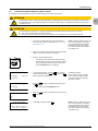
7.5.2
Required Tools and Accessories
7.5.3
Connecting Individual Solar Inverters
Not included in delivery:
–
Connection cable from solar
inverter to monitoring device
~
Connection cable from solar
inverter to solar inverter
8
1
RS485
Cable 3081129500
Termination resistor
EN
Termination resistor
3072438891
Data logger
Fig. 7.10:
Connection of a single solar inverter to a data logger
via RS485
You can order the required accessories from Delta:
Accessories
Connection cable from solar inverter to
solar inverter
(Push/pull cable by Harting, IP67, one side
with blue cable manager, other side with
white cable manager)
1.5 m
3.0 m
5.0 m
10.0 m
20.0 m
Connection cable from solar inverter to
monitoring device
(e.g. SOLIVIA Gateway M1 G2, Solarlog or
Meteocontrol WEB’logger)
Outdoor cable, IP65, with Harting RJ45
PushPull and RJ12 plugs
Termination resistor for RS485
Delta Part number
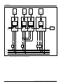
7.5.4
Connecting Multiple Solar Inverters
–
3081186300
3081186500
3081186600
3081186200
3081186400
~
–
RS485
RS485
Cable 308116x00
Cable 3081129500
3081129500
~
–
~
RS485
Cable 308116x00
Termination resistor
3072438891
Data logger
3072438891
If you wish to make the cables yourself, then you must use cable
managers from Harting (IP67-Push/Pull system cable RJ45).
Fig. 7.11:
Connection of multiple solar inverters to a data logger
via RS485
We recommend using a blue cable manager on one side and a
white cable manager on the other side.
Accessories
Cable manager
RJI IP67 data plug PushPull 8-pin white
RJI IP67 data plug PushPull 8-pin blue
Harting Part no.
09 45 145 1500
09 45 145 1510
HARTING Deutschland GmbH & Co. KG (PF 2451, D-32381 Minden, www.harting.com)
Operation and Installation Manual for SOLIVIA 2.0/2.5/3.0/3.3/3.6/5.0 EU G4 TR
33
8. Commissioning
8.
Commissioning
8.1
Before You Begin
The solar inverter must be correctly installed, see “7 Installation”,
p. 24.
Information on operating the display can be found in “5.4 Display
and Buttons”, p. 14.
nOTE
As long as the commissioning procedure has not
been completed, you can go back to any point
in the commissioning procedure at any time by
pressing the ESC button.
nOTE
Always read through each step before starting
the commissioning procedure.
8.2
Selecting the Correct Commissioning
Procedure
The solar inverter must be newly installed:
Country
Belgium
Bulgaria
Czech Republic
Germany
Denmark
France
Greece
Italy
Grid (as shown on display)
BE C10/11 12
BG
CZ
DE LVD
DK LVD
FR UTE
FR ISL. 60 Hz
GR CONTINENT
GR ISLAND
IT BT 21
IT BT 21 > 6kW
Netherlands
Poland
Portugal
Romania
Slovakia
Spain
United Kingdom
NL
PL
PT
RO
SK
ES
ES
ES
UK
UK
UK
RD1699
RD661
ISLAND
G59-2 230
G59-2 240
83-1
Description
Applicable Commissioning Procedure
Belgium as per C10/11, Issue 2012
Bulgaria
Czech Republic
Germany as per VDE AR N 4105
Denmark as per VDE AR N 4105
France as per UTE
French islands 60 Hz
Greece/continent (49.5/50.5 Hz)
Greece/islands (47.5/51 Hz)
Italy as per CEI 0-21:2012-06 for PV
systems equal to or less than 6 kW.
Italy as per CEI 0-21:2012-06 for PV
systems greater than 6 kW.
Netherlands
Portugal
Romania
Slovakia
Spain as per RD 1699
Spain as per RD 661
Spain/islands
United Kingdom as per G59-2 230 V
and 240 V
United Kingdom as per G83-1
“8.3 Commissioning for EN 50438 and VDE
0126 Grids”, p. 35
“8.4 Commissioning for VDE AR N 4105
Grids”, p. 38
“8.3 Commissioning for EN 50438 and VDE
0126 Grids”, p. 35
“8.5 Commissioning in Italy for PV Systems
Below 6 kW”, p. 41
“8.3 Commissioning for EN 50438 and VDE
0126 Grids”, p. 35
The solar inverter must be set up with the same settings as another identical solar inverter. “8.6 Commissioning by Loading Settings from
Other Solar Inverter”, p. 44
The solar inverter is a replacement device for another identical solar inverter.
“8.7 Commissioning After Replacing Solar
Inverter”, p. 47
The solar inverter should be newly set up and the grid to which the solar inverter is conYou can set up a customer-specific grid.
nected is not shown in the list above.
Please contact Delta Support by phone.
34
Operation and Installation Manual for SOLIVIA 2.0/2.5/3.0/3.3/3.6/5.0 EU G4 TR
8. Commissioning
8.3
Commissioning for En 50438 and VDE 0126 Grids
The standard commissioning is valid for the following countries and grids.
Country
Belgium
Bulgaria
France
Greece
Italy
Grid
BE C10/11 12
BG
FR UTE
Netherlands
Portugal
Romania
Slovakia
Spain
Czech Republic
United Kingdom
NL
PT
RO
SK
notes
EN
GR and GR ISLAND
IT BT 21 > 6kW
ES
CZ
UK
UK
UK
Italy as per CEI 0-21:2012-06 for PV
systems greater than 6 kW.
ISLAND, ES RD661 and ES RD1699
G59-2 230
G59-2 240
83-1
United Kingdom as per G59-2 230 V
and 240 V
United Kingdom as per G83-1
1.
Check all connections and cables for damage and correct
seating. Correct the installation if necessary.
2.
Switch on the DC isolating switch.
OFF
→
The startup process of the solar inverter will begin.
After the startup process and the automatic self-test,
the commissioning procedure of the inverter starts
and the Installation menu is displayed.
ON
DC DISCONNECT
Installation
------------------➔Language:
English
continue
3.
To change the language, press the
button and then
set the language using the
buttons. Press the
button to apply the language.
---I
-n
-s
-t
-a
-l
-l
-a
-t
-i
-o
-n
----Language:
English
➔continue
-------------------
4.
---L
-o
-a
-d
--U
-S
-B
--d
-a
-t
-a
---Yes
➔No
-------------------
5.
Grid selection
------------------➔Grid:
CZ
continue
6.
To change the grid, press the
button and then set
the grid using the
buttons. Press the
button to
apply the grid.
-r
-i
-d
--s
-e
-l
-e
-c
-t
-i
-o
-n
-----G
Grid:
CZ
➔continue
-------------------
7.
Press the
the
button.
Press the
the
button.
→
→
Czech | Danish | Dutch | English |
French | German | Italian | Polish |
Portuguese | Romanian | Slovak |
Slovenian | Spanish
buttons to select more and then press
This displays the Load USB Data menu.
Press the
button.
→
Available languages:
buttons to select No and then press the
The Grid Selection menu is displayed.
nOTE: Here you can select the proper
grid for your country.
buttons to select more and then press
The Locked Power Limit menu is displayed.
Operation and Installation Manual for SOLIVIA 2.0/2.5/3.0/3.3/3.6/5.0 EU G4 TR
35
8. Commissioning
Locked power limit
------------------➔Pmax:
_._kW
Smax:
_._kVA
8.
To change the value, press the
button and then set
the value using the
buttons. Press the
button to
apply the value.
nOTE: If you change one of the values, you must fill out the provided
label after commissioning and place it
next to the type plate
nOTE: The configured values can
only be changed with a PIN after commissioning.
nOTE: The configured values are
displayed after commissioning in the
131 View Grid Setup menu.
------------------P
Lm
oa
cx
k:
ed power _
l.
i_
mk
iW
t
Smax:
_._kVA
➔continue
-------------------
9.
Press the
the
button.
→
buttons to select more and then press
The Power Balancing menu is displayed.
Power balancing
------------------➔Balancing:
Off
continue
10. To change the settings, press the
button and then
select the option using the
buttons. Press the
button to apply the setting.
--Power-balancing-Balancing:
Off
➔continue
-------------------
11. Press the
press the
Format
------------------➔Date:
DD.MM.YYYY
Time:
24h
12. To change the value, press the
button and then set
the value using the
buttons. Press the
button to
apply the value.
→
nOTE: The grid load can only be
balanced with a SOLIVIA Gateway M1
G2. If no gateway is connected, the
Balance option will always be set to
Off. Otherwise the solar inverter will
not feed into the grid.
buttons to select continue and then
button.
The Format menu is displayed.
Available date formats:
DD.MM.YYYY | DD/MM/YYYY
DD-MM-YYYY | MM.DD.YYYY
MM/DD/YYYY | MM-DD-YYYY
YYYY.MM.DD | YYYY/MM/DD
YYYY-MM-DD
Available time formats:
12h | 24h
------------------Date: F2
o5
r.
m0
a5
t.2012
Time:
24h
➔continue
------------------Date and time
------------------➔Date:
25.05.2012
Time:
14:26:51
------------------Date
D:
ate25
a.
n0
d5.
t2
i0
m1
e2
Time:
14:26:51
➔continue
-------------------
36
13. Press the
press the
→
buttons to select continue and then
button.
The Date and Time menu is displayed.
14. To change the value, press the
button and then set
the value using the
buttons. Press the
button to
apply the value.
15. Press the
the
button.
→
buttons to select contine and then press
The RS485 menu is displayed.
Operation and Installation Manual for SOLIVIA 2.0/2.5/3.0/3.3/3.6/5.0 EU G4 TR
8. Commissioning
RS485
------------------➔ID:
1
Baudrate:
19200
16. To change the value, press the
button and then set
the value using the
buttons. Press the
button to
apply the value.
nOTE: If multiple solar inverters are
to be connected via RS485, select a
different ID for each inverter. The ID
is also used when saving and loading
settings in order to identify the solar
inverter.
Available IDs:
1 - 254
Available baudrates:
2400 | 4800 | 9600 | 19200 | 38400
------------------ID:
1
RS485
Baudrate:
19200
➔continue
------------------ENTER:
to confirm
ESC:
to reselect
17. Press the
press the
→
buttons to select continue and then
button.
The completion screen will be displayed.
18. Press the
button to complete commissioning.
or
Press the
þ
button to change settings.
Commissioning is now finished.
nOTE
►
The solar inverter offers some optional
functions available for all grids, see “10 Settings”, p. 52.
►
When done with commissioning, save
the settings (see “11.4 Saving Settings”,
p. 65) and swap data (see “11.6 Saving
Swap Data”, p. 67) to a USB drive in
order to be able to use them later.
Operation and Installation Manual for SOLIVIA 2.0/2.5/3.0/3.3/3.6/5.0 EU G4 TR
37
EN
8. Commissioning
8.4
Commissioning for VDE AR n 4105 Grids
The commissioning for VDE AR N 4105 grids is valid for the following countries and grids.
Country
Denmark
Germany
Grid
DK LVD
DE LVD
notes
1.
Check all connections and cables for damage and correct
seating. Correct the installation if necessary.
2.
Switch on the DC isolating switch.
OFF
→
The startup process of the solar inverter will begin.
After the startup process and the automatic self-test,
the commissioning procedure of the inverter starts
and the Installation menu is displayed.
ON
DC DISCONNECT
Installation
------------------➔Language:
English
continue
3.
To change the language, press the
button and then
set the language using the
buttons. Press the
button to apply the language.
---I
-n
-s
-t
-a
-l
-l
-a
-t
-i
-o
-n
----Language:
English
➔continue
-------------------
4.
---L
-o
-a
-d
--U
-S
-B
--d
-a
-t
-a
---Yes
➔No
-------------------
5.
Grid selection
------------------➔Grid:
DE LVD
continue
6.
To change the grid, press the
button and then set
the grid using the
buttons. Press the
button to
apply the grid.
----Netzauswahl---Netz:
DE LVD
➔weiter
-------------------
7.
Press the
press the
PDD settings
------------------➔PDD:
Standard
continue
8.
Press the
press the
→
→
Czech | Danish | Dutch | English |
French | German | Italian | Polish |
Portuguese | Romanian | Slovak |
Slovenian | Spanish
buttons to select continue and then
button.
This displays the Load USB Data menu.
Press the
button.
→
Available languages:
buttons to select No and then press the
The Grid Selection menu is displayed.
nOTE: Here you can select the proper
grid for your country.
buttons to select continue and then
button.
The PDD Settings (settings for grid and system
protection) will be displayed.
To change the settings for the grid and system protection,
press the
button and then set the option using the
buttons. Press the
button to apply the setting.
Available options:
Standard: Loads the settings defined
by the VDE AR N 4105 standard.
Off: Grid and system protection is
deactivated.
User: The parameters can be
manually configured within the limits
defined by the VDE AR N 4105 standard.
38
Operation and Installation Manual for SOLIVIA 2.0/2.5/3.0/3.3/3.6/5.0 EU G4 TR
8. Commissioning
PDD-settings------PDD:
Standard
➔continue
-------------------
PDD settings
------------------➔Umax:
253V
continue
9.
Press the
press the
buttons to select continue and then
button.
→
If the PDD setting is User, an extended PDD Settings menu will be displayed. Continue with Step 10.
→
If the PDD setting is Standard or Off, the Locked
Power Limit menu will be displayed. Continue with
Step 12.
10. To change the value, press the
button and then set
the value using the
buttons. Press the
button to
apply the value.
EN
nOTE: Steps 10 and 11 are only
necessary when the mode User was
set in Step 9.
Available Umax settings:
253 - 264 V (corresponds to 110 115% of 230 V), default is 253 V.
buttons to select more and then press
PDD-settings------Umax:
253V
➔continue
-------------------
11. Press the
the
button.
Locked power limit
------------------➔Pmax:
_._kW
Smax:
_._kVA
12. To change the value, press the
button and then set
the value using the
buttons. Press the
button to
apply the value.
→
The Locked Power Limit menu is displayed.
nOTE: If you change one of the values, you must fill out the provided
label after commissioning and place it
next to the type plate
nOTE: The configured values can
only be changed with a PIN after commissioning.
nOTE: The configured values are
displayed after commissioning in the
131 View Grid Setup menu.
------------------P
Lm
oa
cx
k:
ed power _
l.
i_
mk
iW
t
Smax:
_._kVA
➔continue
-------------------
13. Press the
the
button.
→
buttons to select more and then press
The Power Balancing menu is displayed.
Power balancing
------------------➔Balancing:
Off
continue
14. To change the settings, press the
button and then
select the option using the
buttons. Press the
button to apply the setting.
--Power-balancing-Balancing:
Off
➔continue
-------------------
15. Press the
press the
Format
------------------➔Date:
DD.MM.YYYY
Time:
24h
16. To change the value, press the
button and then set
the value using the
buttons. Press the
button to
apply the value.
→
nOTE: The grid load can only be
balanced with a SOLIVIA Gateway M1
G2. If no gateway is connected, the
Balance option will always be set to
Off. Otherwise the solar inverter will
not feed into the grid.
buttons to select continue and then
button.
The Format menu is displayed.
Available date formats:
DD.MM.YYYY | DD/MM/YYYY
DD-MM-YYYY | MM.DD.YYYY
MM/DD/YYYY | MM-DD-YYYY
YYYY.MM.DD | YYYY/MM/DD
YYYY-MM-DD
Available time formats:
12h | 24h
------------------Date: F2
o5
r.
m0
a5
t.2012
Time:
24h
➔continue
-------------------
17. Press the
press the
→
buttons to select continue and then
button.
The Date and Time menu is displayed.
Operation and Installation Manual for SOLIVIA 2.0/2.5/3.0/3.3/3.6/5.0 EU G4 TR
39
8. Commissioning
Date and time
------------------➔Date:
25.05.2012
Time:
14:26:51
------------------D:
ate25
a.
n0
d5.
t2
i0
m1
e2
Date
Time:
14:26:51
➔continue
------------------RS485
------------------➔ID:
1
Baudrate:
19200
18. To change the value, press the
button and then set
the value using the
buttons. Press the
button to
apply the value.
19. Press the
press the
→
buttons to select continue and then
button.
The RS485 menu is displayed.
20. To change the value, press the
button and then set
the value using the
buttons. Press the
button to
apply the value.
nOTE: If multiple solar inverters are
to be connected via RS485, select a
different ID for each inverter. The ID
is also used when saving and loading
settings in order to identify the solar
inverter.
Available IDs:
1 - 254
Available baudrates:
2400 | 4800 | 9600 | 19200 | 38400
------------------ID:
1
RS485
Baudrate:
19200
➔continue
------------------ENTER:
to confirm
ESC:
to reselect
21. Press the
press the
→
buttons to select continue and then
button.
The completion screen will be displayed.
22. Press the
button to complete commissioning.
or
Press the
þ
button to change settings.
Commissioning is now finished.
nOTE
40
►
If the solar inverter is configured to the DE
LVD oder DK LVD grids, you can also configure active and reactive power control, see
“10.9 Active Power Control”, p. 56.
►
The solar inverter offers some optional
functions available for all grids, see “10 Settings”, p. 52.
►
When done with commissioning, save
the settings (see “11.4 Saving Settings”,
p. 65) and swap data (see “11.6 Saving
Swap Data”, p. 67) to a USB drive in
order to be able to use them later.
Operation and Installation Manual for SOLIVIA 2.0/2.5/3.0/3.3/3.6/5.0 EU G4 TR
8. Commissioning
8.5
Commissioning in Italy for PV Systems Below 6 kW
The standard commissioning is valid for the following countries and grids.
Country
Italy
Grid
IT BT 21
notes
As per CEI 0-21:2012-06 for PV systems equal to or less than 6 kW.
1.
Check all connections and cables for damage and correct
seating. Correct the installation if necessary.
2.
Switch on the DC isolating switch.
OFF
→
EN
The startup process of the solar inverter will begin.
After the startup process and the automatic self-test,
the commissioning procedure of the inverter starts
and the Installation menu is displayed.
ON
DC DISCONNECT
Installation
------------------➔Language:
English
continue
3.
To change the language, press the
button and then
set the language using the
buttons. Press the
button to apply the language.
---I
-n
-s
-t
-a
-l
-l
-a
-t
-i
-o
-n
----Language:
English
➔continue
-------------------
4.
---L
-o
-a
-d
--U
-S
-B
--d
-a
-t
-a
---Yes
➔No
-------------------
5.
Grid selection
------------------➔Grid:
IT BT 21
continue
6.
To change the grid, press the
grid to IT BT 21 using the
button to apply the grid.
--Grid-selection--Grid:
IT BT 21
➔continue
-------------------
7.
Press the
press the
Local control
------------------➔Local control:
Off
continue
8.
To change the settings, press the
button and then set
the option using the
buttons. Press the
button
to apply the setting.
---Local-control--Local control: Off
➔continue
-------------------
9.
Press the
press the
Press the
press the
→
→
→
Czech | Danish | Dutch | English |
French | German | Italian | Polish |
Portuguese | Romanian | Slovak |
Slovenian | Spanish
buttons to select continue and then
button.
This displays the Load USB Data menu.
Press the
button.
→
Available languages:
buttons to select No and then press the
The Grid Selection menu is displayed.
button and then set the
buttons. Press the
nOTE: Here you can select the proper
grid for your country.
buttons to select continue and then
button.
The Local Control menu is then displayed.
buttons to select continue and then
button.
The Locked Power Limit menu is displayed.
Operation and Installation Manual for SOLIVIA 2.0/2.5/3.0/3.3/3.6/5.0 EU G4 TR
41
8. Commissioning
Locked power limit
------------------➔Pmax:
_._kW
Smax:
_._kVA
10. To change the value, press the
button and then set
the value using the
buttons. Press the
button to
apply the value.
nOTE: If you change one of the values, you must fill out the provided
label after commissioning and place it
next to the type plate
nOTE: The configured values can
only be changed with a PIN after commissioning.
nOTE: The configured values are
displayed after commissioning in the
131 View Grid Setup menu.
------------------P
Lm
oa
cx
k:
ed power _
l.
i_
mk
iW
t
Smax:
_._kVA
➔continue
-------------------
11. Press the
the
button.
→
buttons to select more and then press
The Power Balancing menu is displayed.
Power balancing
------------------➔Balancing:
Off
continue
12. To change the settings, press the
button and then
select the option using the
buttons. Press the
button to apply the setting.
--Power-balancing-Balancing:
Off
➔continue
-------------------
13. Press the
press the
Format
------------------➔Date:
DD.MM.YYYY
Time:
24h
14. To change the value, press the
button and then set
the value using the
buttons. Press the
button to
apply the value.
→
nOTE: The grid load can only be
balanced with a SOLIVIA Gateway M1
G2. If no gateway is connected, the
Balance option will always be set to
Off. Otherwise the solar inverter will
not feed into the grid.
buttons to select continue and then
button.
The Format menu is displayed.
Available date formats:
DD.MM.YYYY | DD/MM/YYYY
DD-MM-YYYY | MM.DD.YYYY
MM/DD/YYYY | MM-DD-YYYY
YYYY.MM.DD | YYYY/MM/DD
YYYY-MM-DD
Available time formats:
12h | 24h
------------------Date: F2
o5
r.
m0
a5
t.2012
Time:
24h
➔continue
------------------Date and time
------------------➔Date:
25.05.2012
Time:
14:26:51
------------------Date
D:
ate25
a.
n0
d5.
t2
i0
m1
e2
Time:
14:26:51
➔continue
-------------------
42
15. Press the
press the
→
buttons to select continue and then
button.
The Date and Time menu is displayed.
16. To change the value, press the
button and then set
the value using the
buttons. Press the
button to
apply the value.
17. Press the
press the
→
buttons to select continue and then
button.
The RS485 menu is displayed.
Operation and Installation Manual for SOLIVIA 2.0/2.5/3.0/3.3/3.6/5.0 EU G4 TR
8. Commissioning
RS485
------------------➔ID:
1
Baudrate:
19200
18. To change the value, press the
button and then set
the value using the
buttons. Press the
button to
apply the value.
nOTE: If multiple solar inverters are
to be connected via RS485, select a
different ID for each inverter. The ID
is also used when saving and loading
settings in order to identify the solar
inverter.
Available IDs:
1 - 254
Available baudrates:
2400 | 4800 | 9600 | 19200 | 38400
------------------ID:
1
RS485
Baudrate:
19200
➔continue
-------------------
19. Press the
press the
→
buttons to select continue and then
button.
The completion screen will be displayed.
ENTER:
to confirm
ESC:
to reselect
20. Press the
610
IT Autotest
------------------➔Perform autotest
AT Report 1
21. Select Perform autotest using the
buttons, then
press the
button to perform the autotest.
611 Perform autotest
22. The Autotest checks the proper operation of the grid and
system protection.
→
→
button.
The 610 IT Autotest (Italy autotest) menu is displayed.
The autotest starts.
nOTE: For PV systems greater than
6 kW, an autotest is not required
by CEI 0-21:2012-06. For this reason, the menu will not be displayed
when the IT BT 21 > 6kW grid is
selected.
...test ongoing...
612 AT Report 1
Result:
Pass
12.08.2012 09:23:35
IT-Grid:
00.01.00
23. The test result is displayed after the autotest is completed.
þ
If the autotest is successful, commissioning is complete.
nOTE: The solar inverter may only
be put into operation when the overall
test result of the last autotest is Pass.
The reports for the last five autotests
are saved.
nOTE: See Chapter “12.6 Autotest for
Italy”, p. 77 for more detailed information on the autotest.
nOTE
►
The solar inverter offers some optional
functions available for all grids, see “10 Settings”, p. 52.
►
When done with commissioning, save
the settings (see “11.4 Saving Settings”,
p. 65) and swap data (see “11.6 Saving
Swap Data”, p. 67) to a USB drive in
order to be able to use them later.
Operation and Installation Manual for SOLIVIA 2.0/2.5/3.0/3.3/3.6/5.0 EU G4 TR
43
EN
8. Commissioning
8.6
Commissioning by Loading Settings from Other Solar Inverter
It is possible in all countries and for all grids to load the settings from another solar inverter.
ATTEnTIOn
The IP 65 degree of protection is no longer guaranteed when the USB interface protective cover is removed.
► Only remove the protective cover when necessary.
► Always use the Micro-USB stick provided. The protective cover is designed to fit over the Micro-USB stick.
1.
If you have not already done so, save the settings of the
other solar inverter to a USB drive, see “11.3 Firmware
Updating”, p. 64.
2.
Check all connections and cables for damage and correct
seating. Correct the installation if necessary.
3.
Switch on the DC isolating switch.
OFF
→
nOTE: The STUP_###.CFG file must
be in the main directory of the USB
drive. The ### characters represent
the RS485 ID of the solar inverter
from which the data is to be loaded,
for example "001".
The startup process of the solar inverter will begin.
After the startup process and the automatic self-test,
the commissioning procedure of the inverter starts
and the Installation menu is displayed.
ON
DC DISCONNECT
Installation
------------------➔Language:
English
continue
4.
---I
-n
-s
-t
-a
-l
-l
-a
-t
-i
-o
-n
----Language:
English
➔continue
-------------------
5.
Load USB data
------------------➔Yes
No
6.
Press the
button.
7.
Insert USB pendrive and press
8.
Press the
then press the
Load USB data
To change the language, press the
button and then
set the language using the
buttons. Press the
button to apply the language.
Press the
press the
→
→
Czech | Danish | Dutch | English |
French | German | Italian | Polish |
Portuguese | Romanian | Slovak |
Slovenian | Spanish
buttons to select continue and then
button.
This displays the Load USB Data menu.
buttons to select Yes and then press the
nOTE: The STUP_###.CFG file must
be in the main directory of the USB
drive. The ### characters represent
the RS485 ID of the solar inverter
from which the data is to be loaded,
for example "001".
.
Insert USB Pendrive
and press ENTER
Load USB data
------------------➔Load settings
Load swap data
Available languages:
buttons to select Load Settings and
button.
The solar inverter will then search for files on the
USB drive.
nOTE: If the message No files
found is displayed, make sure the
files are in the main directory of the
USB drive.
When files are found, the Select RS485 ID menu is
displayed.
44
Operation and Installation Manual for SOLIVIA 2.0/2.5/3.0/3.3/3.6/5.0 EU G4 TR
8. Commissioning
9.
Select RS485 ID
➔
ID:
1
Press the
the
button.
→
buttons to select the ID and then press
The data is then verified and loaded.
nOTE: If the message Pendrive
error is displayed, make sure the
USB drive is properly inserted or that
the file is not damaged.
A message is displayed when the loading process is
successful.
Load data
Successful
Press ENTER
10. Press the
→
EN
button to confirm.
If the asymmetrical grid load balancing was activated on the solar inverter from which the data was
loaded, the following message appears.
Power balancing is
activated
→
If active or apparent power limitation was activated
on the solar inverter from which the data was
loaded, the following message appears.
The maximum power
of that inverter has
been limited to
##.#W/##.#kVA
11. If the above mentioned messages appear, press the
button to confirm each.
buttons to select No and then press the
Ch
-a
-n
-g
-e
--l
-o
-a
-d
-e
-d
--v
-a
-l
-u
-e
-s
Yes
➔No
-------------------
12. Press the
button.
Date and time
------------------➔Date:
25.05.2012
Time:
14:26:51
13. To change the value, press the
button and then set
the value using the
buttons. Press the
button to
apply the value.
------------------Date
D:
ate25
a.
n0
d5.
t2
i0
m1
e2
Time:
14:26:51
➔continue
------------------RS485
------------------➔ID:
1
Baudrate:
19200
→
The Date and Time menu is displayed.
14. Press the
press the
→
nOTE: If you wish to change the
loaded values, select Yes. Commissioning then continues with the grid
selection and is the same as the initial
commissioning.
buttons to select continue and then
button.
The RS485 menu is displayed.
15. To change the value, press the
button and then set
the value using the
buttons. Press the
button to
apply the value.
nOTE: If multiple solar inverters are
to be connected via RS485, select a
different ID for each inverter. The ID
is also used when saving and loading
settings in order to identify the solar
inverter.
Available IDs:
1 - 254
Available baudrates:
2400 | 4800 | 9600 | 19200 | 38400
------------------ID:
1
RS485
Baudrate:
19200
➔continue
-------------------
16. Press the
press the
→
buttons to select continue and then
button.
The completion screen will be displayed.
Operation and Installation Manual for SOLIVIA 2.0/2.5/3.0/3.3/3.6/5.0 EU G4 TR
45
8. Commissioning
ENTER:
to confirm
ESC:
to reselect
17. Press the
button to complete commissioning.
or
Press the
þ
button to change settings.
Commissioning is now finished.
nOTE
46
►
If the solar inverter is configured to the DE
LVD oder DK LVD grids, you can also configure active and reactive power control, see
“10.9 Active Power Control”, p. 56.
►
The solar inverter offers some optional
functions available for all grids, see “10 Settings”, p. 52.
►
When done with commissioning, save
the settings (see “11.4 Saving Settings”,
p. 65) and swap data (see “11.6 Saving
Swap Data”, p. 67) to a USB drive in
order to be able to use them later.
Operation and Installation Manual for SOLIVIA 2.0/2.5/3.0/3.3/3.6/5.0 EU G4 TR
8. Commissioning
8.7
Commissioning After Replacing Solar Inverter
It is possible in all countries and for all grids to load the settings from another solar inverter.
ATTEnTIOn
In this chapter, the term "swap" means the replacement of a damaged solar inverter with a new device of the same type.
EN
The replacement may only be performed after consulting Delta Solar Support. The support team will discuss the correct
procedure with you.
ATTEnTIOn
The IP 65 degree of protection is no longer guaranteed when the USB interface protective cover is removed.
► Only remove the protective cover when necessary.
► Always use the Micro-USB stick provided. The protective cover is designed to fit over the Micro-USB stick.
1.
If you have not already done so, save the settings of
the other solar inverter to a USB drive, see “11.6 Saving
Swap Data”, p. 67.
2.
Check all connections and cables for damage and correct
seating. Correct the installation if necessary.
3.
Switch on the DC isolating switch.
OFF
→
nOTE: The SWAP_###.CFG file must
be in the main directory of the USB
drive. The ### characters represent
the RS485 ID of the solar inverter
from which the data is to be loaded,
for example "001".
The startup process of the solar inverter will begin.
After the startup process and the automatic self-test,
the commissioning procedure of the inverter starts
and the Installation menu is displayed.
ON
DC DISCONNECT
Installation
------------------➔Language:
English
continue
4.
---I
-n
-s
-t
-a
-l
-l
-a
-t
-i
-o
-n
----Language:
English
➔continue
-------------------
5.
Load USB data
------------------➔Yes
No
6.
Press the
button.
7.
Insert USB Pendrive and press
Load USB data
To change the language, press the
button and then
set the language using the
buttons. Press the
button to apply the language.
Press the
the
button.
→
Available languages:
Czech | Danish | Dutch | English |
French | German | Italian | Polish |
Portuguese | Romanian | Slovak |
Slovenian | Spanish
buttons to select more and then press
This displays the Load USB Data menu.
buttons to select Yes and then press the
Insert USB Pendrive
and press ENTER
Operation and Installation Manual for SOLIVIA 2.0/2.5/3.0/3.3/3.6/5.0 EU G4 TR
.
nOTE: The STUP_###.CFG file must
be in the main directory of the USB
drive. The ### characters represent
the RS485 ID of the solar inverter
from which the data is to be loaded,
for example "001".
47
8. Commissioning
---L
-o
-a
-d
--U
-S
-B
--d
-a
-t
-a
---Load settings
➔Load swap data
-------------------
8.
Press the
then press the
→
buttons to select Load Swap Data and
button.
The solar inverter will then search for files on the
USB drive.
nOTE: If the message No files
found is displayed, make sure the
files are in the main directory of the
USB drive.
When files are found, the Select RS485 ID menu is
displayed.
9.
Select RS485 ID
➔
ID:
1
Press the
the
button.
→
buttons to select the ID and then press
The data is then verified and loaded.
nOTE: If the message Pendrive
error is displayed, make sure the
USB drive is properly inserted.
A message is displayed when the loading process is
successful.
Load data
Successful
Press ENTER
10. Press the
→
button to confirm.
If the asymmetrical grid load balancing was activated on the solar inverter from which the data was
loaded, the following message appears.
Power balancing is
activated
→
If active or apparent power limitation was activated
on the solar inverter from which the data was
loaded, the following message appears.
The maximum power
of that inverter has
been limited to
##.#W/##.#kVA
11. If the above mentioned messages appear, press the
button to confirm each.
buttons to select No and then press the
Ch
-a
-n
-g
-e
--l
-o
-a
-d
-e
-d
--v
-a
-l
-u
-e
-s
Yes
➔No
-------------------
12. Press the
button.
Date and time
------------------➔Date:
25.05.2012
Time:
14:26:51
13. To change the value, press the
button and then set
the value using the
buttons. Press the
button to
apply the value.
------------------D:
ate25
a.
n0
d5.
t2
i0
m1
e2
Date
Time:
14:26:51
➔continue
------------------RS485
------------------➔ID:
1
Baudrate:
19200
→
The Date and Time menu is displayed.
14. Press the
press the
→
nOTE: If you wish to change the
loaded values, select Yes. Commissioning then continues with the grid
selection and is the same as the initial
commissioning.
buttons to select continue and then
button.
The RS485 menu is displayed.
15. To change the value, press the
button and then set
the value using the
buttons. Press the
button to
apply the value.
nOTE: If multiple solar inverters are
to be connected via RS485, select a
different ID for each inverter. The ID
is also used when saving and loading
settings in order to identify the solar
inverter.
Available IDs:
1 - 254
Available baudrates:
2400 | 4800 | 9600 | 19200 | 38400
48
Operation and Installation Manual for SOLIVIA 2.0/2.5/3.0/3.3/3.6/5.0 EU G4 TR
8. Commissioning
------------------ID:
1
RS485
Baudrate:
19200
➔continue
------------------ENTER:
to confirm
ESC:
to reselect
16. Press the
press the
→
buttons to select continue and then
button.
The completion screen will be displayed.
17. Press the
EN
button to complete commissioning.
or
Press the button to change settings.
þ
Commissioning is now finished.
nOTE
►
If the solar inverter is configured to the DE
LVD oder DK LVD grids, you can also configure active and reactive power control, see
“10.9 Active Power Control”, p. 56.
►
The solar inverter offers some optional
functions available for all grids, see “10 Settings”, p. 52.
►
When done with commissioning, save
the settings (see “11.4 Saving Settings”,
p. 65) and swap data (see “11.6 Saving
Swap Data”, p. 67) to a USB drive in
order to be able to use them later.
Operation and Installation Manual for SOLIVIA 2.0/2.5/3.0/3.3/3.6/5.0 EU G4 TR
49
9. Production Information
9.
Production Information
Structure
Submenu
411 Current Overview
nOTE
All production information is provided for orientation purposes only. The measuring devices and
meters provided by the electricity supply company are the authoritative source of information
for invoicing.
9.1
Current operating state (see “12 Diagnostics and Troubleshooting”, p. 69)
411 Current Overview
Now:
_W
Day:
_Wh
Normal operation
Overview
The 400 Production Info menu contains current data and statistics. The information is write-protected and cannot be edited.
►
Select Production Info from the main menu.
→
This displays the 400 Production Info menu.
412 Current Data AC
400 Production Info
------------------➔Current Data
Day statistics
Contents
Current data for
power, AC, PV, insulation
Statistics for AC, PV
and ISO
420 Day Statistics
430 Week Statistics
440 Month Statistics
450 Year Statistics
460 Total Statistics
470 Feed-In Settings Settings for currency
and revenue per kWh
480 Event Journal
List of operating state
messages
490 History
Statistics for the last
seven days the solar
inverter was in operation.
9.2
Description
“9.2 Current
Data”, p. 50
“9.3 Other Statistics”, p. 50
“10.7 Currency
and Credit per
kWh”, p. 55
“12.4.1 “External
events” log”,
p. 75
“9.3 Other Statistics”, p. 50
416 Current Data PV
The current production data is provided in 410 Current Data.
Access
You access the menu by navigating to Main Menu > Production Info > Current Data.
→
This displays the 410 Current Data menu.
410 Current Data
------------------➔Current Overview
Current Data AC
Displays DC voltage, DC current
416 Current Data PV
PV1 voltage:
PV1 current:
41A Date and Time
_V
_,_A
Displays current date and time
Use the 110 Date and Time menu
to set the values, see “10.3 Date and
time”, p. 53.
41A Date and Time
Date:
Time:
41B Current isolat.
09/14/2011
13:15:22
Displays maximum and minimum
isolation resistance
41B Current isolat.
R iso+:
R iso-:
Current Data
Relevant Menu
►
If there are messages, the list of messages can be opened by pressing the
button. For a detailed description,
see Chapter “12 Diagnostics and
Troubleshooting”, p. 69.
Displays voltage, current, frequency,
active power P, reactive power Q, DC
component
412 Current Data AC
-------------------L1 voltage:
_V
L1 current:
_,_A
Structure of 400 Production Info Menu
Submenu
410 Current Data
Contents and Sample Display
Current power and energy generation
for the current day.
9.3
____kΩ
____kΩ
Other Statistics
Menu
420 Day Statistics
430 Week Statistics
440 Month Statistics
450 Year Statistics
460 Total Statistics
490 History
Example display
420 Day Statistics
-----------------➔Day Stats AC
Day Stats DC–
The statistics for day, week, month, year and total production time
all provide the same type of data.
50
Operation and Installation Manual for SOLIVIA 2.5/3.0/3.3/3.6/5.0 EU G4 TR
9. Production Information
The 490 History menu shows the statistics for the last seven days
the solar inverter was in operation. These seven days do not have
to be consecutive.
03
Submenu
491 Day ...
...
490 History
------------------➔Day:
04/15/2012
Day:
04/13/2012
497 Day ...
Contents
Statistics for energy, runtime, revenue
Information on configuring the revenue settings can be found under
“10.7 Currency and Credit per kWh”,
p. 55.
421 Day Stats AC
-------------------Energy:
----Wh
Runtime:
-:--h
Displays for:
Δf
Minimum/maximum
frequency
Imax
Maximum current
ΔU
Minimum/maximum
voltage
Pmax
Maximum active power
Qmax
Maximum reactive
power
Qmin
Minimum reactive power
9.4
All statistics can be deleted (except for 410 Current Data). The
procedure is always the same.
1.
422
PV1
PV1
PV1
423 Day Stats ISO
433 Week Stats ISO
443 Month Stats ISO
453 Year Stats ISO
463 Total Stats ISO
Go Production Info > Feed-In Settings > Delete Statistics.
→
2.
Use the
buttons to select the statistics you want to
delete (e.g. Reset Day Stat.) and press
.
→
3.
A confirmation prompt is displayed.
To delete statistics, use the
option, then press
.
buttons to select the Yes
Reset Day Stat.
No
➔Yes
-----------------→
A confirmation message is displayed.
Reset Day Stat.
Maximum power
Maximum current
Maximum voltage
Day Stats DC–
_W
Pmax:
Imax:
_,_A
Umax:
_V
This displays the 471 Statistics menu.
471 Statistics
------------------➔Reset Day Stat.
Reset Week Stat.
Displays for:
Pmax
Imax
Umax
Deleting Statistics
Description
421 Day Stats AC
L1 Δf: --.--/--.--Hz
L1 Imax:
--.--A
L1 ΔU:
---/---V
422 Day Stats DC–
432 Week Stats DC–
442 Month Stats DC–
452 Year Stats DC–
462 Total Stats DC–
The statistics contain the same information as menus 421, 422 and 423.
491 Day
04/16/2012
-------------------Energy:
____Wh
Runtime:
_:__h
Structure
Submenu
421 Day Stats AC
431 Week Stats AC
441 Month Stats AC
451 Year Stats AC
461 Total Stats AC
Contents
Statistics for the last seven days the
solar inverter was in operation.
Successful
Press ENTER
þ
The statistics are deleted.
Statistics for maximum/minimum
insulation resistance
R iso
max
R iso
min
Maximum insulation
resistance
Minimum insulation
resistance
423 Day Stats ISO
R iso max:
R iso min:
____kΩ
____kΩ
Operation and Installation Manual for SOLIVIA 2.5/3.0/3.3/3.6/5.0 EU G4 TR
51
EN
10. Settings
10.
Settings
10.1
Overview
Setting
Display language
Date and time
Date and time formats
Backlighting and contrast
RS485 (EIA485)
Currency and Credit per kWh
Reset Statistics
Active power control
Active power reduction
Active power by frequency
Reactive power control
Power factor by active power
Constant power factor
Local control (Italy only)
Shadowing (extended MPP tracker)
Insulation and grounding monitoring
Standard menu
10.2
Display language
Menu
100 Install Settings
Description
Page 52
Page 53
Page 53
Page 54
Page 54
Page 55
Page 55
Page 56
Page 57
Page 58
Page 60
Page 60
Page 61
Page 61
Page 62
Allows the display language to be configured.
Accessing the Menu
Main Menu > Install Settings
1.
SOLIVIA ##
------------------➔Install settings
Options
In the main menu, press the
buttons to select Install
Settings and then press the
button.
1 0 0 I n s t a l l s e t t i n g s 2.
------------------➔Language:
English
Date and time
Press the
buttons to select Language and then press
the
button.
1 0 0 I n s t a l l s e t t i n g s 3.
------------------➔Language:
English
Date and time
Press the
buttons to
select the language and then
press the
button.
Access via Button Combinations
Press the ESC and
buttons simultaneously.
ConfigurableParameters
Display Text
Language
Designation
Language
Description
The display language.
Czech | Danish | Dutch | English |
French | German | Italian | Portuguese | Romanian | Slovak |
Slovenian | Spanish
52
Operation and Installation Manual for SOLIVIA 2.0/2.5/3.0/3.3/3.6/5.0 EU G4 TR
10. Settings
10.3
Date and time
Menu
10.4
110 Date and time
Date and time formats
Menu
111 Format
Description
Description
Allows the date and time to be configured.
Allows the date and time formats to be configured.
Accessing the Menu
Accessing the Menu
Main menu > Install settings > Date and Time
Main Menu > Install Settings > Date and Time > Format
1.
SOLIVIA ##
------------------➔Install settings
Options
In the main menu, press the
buttons to select Install
Settings and then press the
button.
1.
SOLIVIA ##
------------------➔Install settings
Options
In the main menu, press the
buttons to select Install
Settings and then press the
button.
-0
--I
-n
-s
-t
-a
-l
-l
--s
-e
-t
-t
-i
-n
-g
-s
- 2.
10
Language:
English
➔Date and time
Display settings
Press the
buttons to
select Date and Time and then
press the
button.
-0
--I
-n
-s
-t
-a
-l
-l
--s
-e
-t
-t
-i
-n
-g
-s
- 2.
10
Language:
English
➔Date and time
Display settings
Press the
buttons to
select Date and Time and then
press the
button.
110 Date and time
3.
------------------➔Date:
25.05.2012
Time:
14:26:51
Select a parameter with the
buttons. Press the
button to change the value.
ConfigurableParameters
Display Text
Date
Designation
Date
Time
Time
Description
Freely configurable according to
the selected date format
Freely configurable according to
the selected time format
------------------11
D0
atD
ea
:te2a
5n
.d
05t
.i
2m
0e
12
3.
Time:
14:26:51
➔Format
------------------111
Format
4.
------------------➔Date:
DD.MM.YYYY
Time:
24h
EN
Press the
buttons to
select Format and then press
the
button.
Select a parameter with the
buttons. Press the
button to change the value.
ConfigurableParameters
Display Text
Date
Designation
Date format
Description
DD.MM.YYYY
DD/MM/YYYY
DD-MM-YYYY
MM.DD.YYYY
MM/DD/YYYY
MM-DD-YYYY
Time
Operation and Installation Manual for SOLIVIA 2.0/2.5/3.0/3.3/3.6/5.0 EU G4 TR
Time format
YYYY.MM.DD
YYYY/MM/DD
YYYY-MM-DD
12h | 24h
53
10. Settings
10.5
Backlighting, contrast
Menu
10.6
120 Display settings
RS485 (EIA485) Settings
Menu
140 RS485
Description
Description
Allows backlighting and contrast to be configured.
Allows the ID and baudrate of the RS485 interface to be configured.
Accessing the Menu
Accessing the Menu
Main Menu > Install Settings > Display Settings
Main Menu > Install Settings > RS485
1.
SOLIVIA ##
------------------➔Install settings
Options
In the main menu, press the
buttons to select Install
Settings and then press the
button.
1.
SOLIVIA ##
------------------➔Install settings
Options
In the main menu, press the
buttons to select Install
Settings and then press the
button.
------------------10
L0
anI
gn
us
at
ga
el
:l se
Et
nt
gi
ln
ig
ss
h 2.
Date and time
➔Display settings
Grid selection
Press the
buttons to
select Display Settings and
then press the
button.
Date and time
10
D0
isI
pn
ls
at
yal
sl
ets
te
it
nt
gi
s n g s 2.
Grid selection
➔RS485
-------------------
Press the
buttons to
select RS485 and then press
the
button.
1 2 0 D i s p l a y s e t t i n g s 3.
------------------➔Contrast:
10
Backlight:
Auto
Select a parameter with the
buttons. Press the
button to change the value.
140
RS485
3.
------------------➔ID:
1
Baudrate:
19200
ConfigurableParameters
ConfigurableParameters
Display Text
Backlight
Display Text
ID
Designation
Description
Display backlightingAuto | On
Auto = The backlighting
switches on when a display
button is pressed.
Contrast
Display contrast
On = The backlighting is
always switched on.
1 - 10
Baudrate
Select a parameter with the
buttons. Press the
button to change the value.
Designation
Description
Solar Inverter Iden- 1 - 254
tification Number
Baudrate
2400 | 4800 | 9600 | 19200
| 38400, the standard is
19200
nOTE
Connecting Multiple Solar Inverters via RS485
► Select a different ID for each solar inverter.
► A termination resistor must be connected
to the last solar inverter in the series (see
“7.5 Connecting RS485 (EIA485) - Optional”,
p. 32).
► This termination resistor can be ordered from
Delta, see “16.2 Overview of Menu Structure”, p. 83.
54
Operation and Installation Manual for SOLIVIA 2.0/2.5/3.0/3.3/3.6/5.0 EU G4 TR
10. Settings
10.7
Currency and Credit per kWh
Menu
470 Feed-In Settings
10.8
Reset Statistics
Menu
471 Statistics
Description
Description
Allows the currency and credit per kWh to be configured. The statistics can also be reset.
Allows the statistics to be reset. The currency and credit per kWh
can also be configured.
Accessing the Menu
Accessing the Menu
Main Menu > Install Settings > RS485
Main Menu > Production Info> Feed-In Settings > Statistics
Install settings
OptiS
oO
nL
sIVIA ##
USB features
➔Production info
Diagnostic&Alarm
Month statistics
40
Y0
eaP
rro
sd
tu
ac
tt
ii
so
tn
ici
snfo
Total statistics
➔Feed-in settings
Event journal
In the main menu, press the
buttons to select Production Info and then press the
button.
2.
Press the
buttons to
select Feed-In Settings and
then press the
button.
Month statistics
40
Y0
eaP
rro
sd
tu
ac
tt
ii
so
tn
ici
snfo
Total statistics
➔Feed-in settings
Event journal
Select a parameter with the
buttons. Press the
button to change the value.
------------------C0
urF
ree
nd
cyi
:n settin
Eg
Us
R 3.
47
Euro / kWh:
0.20
➔Statistics
-------------------
4 7 0 F e e d - i n s e t t i n g s 3.
------------------➔Currency:
EUR
Euro / kWh:
0.20
ConfigurableParameters
Display Text
Currency
EUR/kWh
Statistics
Install settings
OptiS
oO
nL
sIVIA ##
USB features
➔Production info
Diagnostic&Alarm
1.
Designation
Currency
Description
Freely configurable, no predefined values.
EUR/kWh
Freely configurable,
no predefined values.
The amount per kWh is
required for the revenue
calculation.
Deleting Statistics Allows individual statistics to be deleted, see
“9.4 Deleting Statistics”,
p. 51.
Operation and Installation Manual for SOLIVIA 2.0/2.5/3.0/3.3/3.6/5.0 EU G4 TR
1.
In the main menu, press the
buttons to select Production Info and then press the
button.
2.
Press the
buttons to
select Feed-In Settings and
then press the
button.
EN
Press the
buttons to select Statistics and then press
the
button.
471 Statistics
4.
------------------➔Reset day stat.
Reset week stat.
Press the
buttons to
select statistics to delete and
then press the
button.
Reset-day-stat. - - 5.
--No
➔Yes
-------------------
Press the
buttons to
select Yes and then press the
button.
ConfigurableParameters
Display Text
Day stats
Week stats
Month stats
Year stats
Total stats
History
Designation
Day statistics
Week statistics
Month statistics
Year statistics
Total statistics
History
Description
Statistics for the last seven
days the solar inverter was
in operation.
55
10. Settings
10.9
Active Power Control
nOTE
10.9.2
Active Power Reduction
Menu
Active power control is only available for DE LVD
and DK LVD grids.
511 Power Reduction
nOTE
The settings in the 511 Power Reduction menu
affect the "Power Factor by Active Power cos φ
(P)" function, see “10.10.2 Power Factor by
Active Power cos φ (P)”, p. 58.
nOTE
Changes to active and reactive power control
can affect energy production.
Ask your installer before changing the settings.
10.9.1
This mode is available for LVD grids.
The maximum permissible active power can be set as a percentage
of the maximum power of the solar inverter.
Overview
Function/Mode
Active power reduction
Active power by frequency
Description
Description
Limits the maximum fed active power
Limits the fed active power depending on
grid frequency
To deactivate this function, set the value to "0 %".
If a power limit was set during commissioning, the percent value
relates to the maximum active power that was set.
Example:
You have a SOLIVIA 5.0 EU G4 TR and the maximum active power
Pmax at commissioning is limited to 4 kW.
If you set 80 % in the 511 Power Reduction menu, the maximum
permitted active power is calculated as 4 kW x 80 % = 3.2 kW.
Accessing the Menu
Main Menu > User Settings > Active PwCtrl > Power Reduction
Options
1. In the main menu, press the
USB S
fO
eL
aI
tV
uI
rA
es##
buttons to select User
Production info
Settings and then press the
➔User settings
button.
Diagnostic&Alarm
C h a n g e s c o u l d a f f e c t 2.
energy production.
Ask your installer
for assistance.
Press the
button to confirm.
500 User settings
3.
------------------➔Active PwCtrl
Reactive PwCtrl
Press the
buttons to
select Active PwCtrl and then
press the
button.
510 Active PwCtrl
4.
------------------➔Power reduction
Power vs freq
Press the
buttons to
select Power Reduction and
then press the
button.
511 Power reduction
5.
------------------➔Max power:
0%
-------------------
Press the
the value.
button to change
ConfigurableParameters
Display Text
Max power
56
Designation
Maximum active
power
Description
Limits the active power to
the set value.
Operation and Installation Manual for SOLIVIA 2.0/2.5/3.0/3.3/3.6/5.0 EU G4 TR
10. Settings
10.9.3
Active Power by Frequency P(f)
Accessing the Menu
Main Menu > User Settings > Active PwCtrl > Power vs freq
Menu
512 Power/Frequency
Description
Allows the statistics to be reset. The currency and credit per kWh
can also be configured.
This function alters the fed active power depending on the grid
frequency. If a starting frequency is exceeded, the fed active power
is limited. If a stopping frequency is exceeded, the active power is
no longer fed.
Behavior as per VDE AR N 4105 is described below.
Variant 1: The grid frequency alters between fStart and fStop.
Pm
Gradient (%/Hz)
fstart
Fig. 10.1:
fstop
f (Hz)
Function P(f), variant 1
Once the grid frequency exceeds the value fStart, the value of the
active power Pm being fed at this moment is automatically saved
and active power limiting is activated.
As long as the grid frequency stays above fStart and under fStop, the
fed active power value runs along the gradients: Active power drops
with increasing grid frequency and increases with decreasing grid
frequency.
Options
USB S
fO
eL
aI
tV
uI
rA
es##
Production info
➔User settings
Diagnostic&Alarm
1.
In the main menu, press the
buttons to select User
Settings and then press the
button.
C h a n g e s c o u l d a f f e c t 2.
energy production.
Ask your installer
for assistance.
Press the
500 User settings
3.
------------------➔Active PwCtrl
Reactive PwCtrl
Press the
buttons to
select Active PwCtrl and then
press the
button.
51
-0
--A
-c
-t
-i
-v
-e
--P
-w
-C
-t
-r
-l
- - - - 4.
Power reduction
➔Power vs freq
-------------------
Press the
buttons to
select Power vs freq and then
press the
button.
512 Power vs freq
5.
------------------➔Start freq: 50.20Hz
Stop freq: 51.50Hz
Select a parameter with the
buttons. Press the
button to change the value.
button to confirm.
ConfigurableParameters
Display Text
Start freq
Designation
Start frequency
Description
Frequency at which the
feeding of active power is
limited.
Value range: 50.00
- 65.00 Hz
Variant 2: The grid frequency exceeds fStop.
Stop freq
Pm
EN
Stop frequency
Gradient (%/Hz)
Standard: 50.20 Hz
Frequency at which the
feeding of active power is
stopped.
Value range: 50.00
- 65.00 Hz
fstart
Fig. 10.2:
fstop
Gradient
f (Hz)
Function P(f), variant 2
Gradient
Standard: 51.50 Hz
Adjustment of the fed
active power in percent
per Hz.
Value range: 0 - 150 %
Standard: 40 %
When the grid frequency exceeds fStart but then remains under fStop,
the solar inverter behaves as described in variant 1.
However, as soon as the grid frequency exceeds fStop, the active
power feed is stopped.
Active power feed will resume once the grid frequency falls below
fStart. Once resumed, the active power will increase by 10% per
minute.
Operation and Installation Manual for SOLIVIA 2.0/2.5/3.0/3.3/3.6/5.0 EU G4 TR
57
10. Settings
10.10 Reactive Power Control
10.10.2 PowerFactorbyActivePowercosφ(P)
nOTE
Menu
Reactive power control is only available for DE
LVD and DK LVD grids.
520 Reactive PwCtrl
Description
This function can be used to determine a separate cos φ for four
different power ratios P/Pn (see “Fig. 10.3 Setting Ranges for “cos φ
(P)” Function”, p. 58).
nOTE
Changes to active and reactive power control
can affect energy production.
Ask your installer before changing the settings.
10.10.1 Overview
Function/Mode
Description
Power factor by active For setting a value of cos φ (inductive or
power
capacitive) depending on the active power
ratio P/Pn
Constant power factor For setting a fixed value for cos φ (inductive or capacitive)
P/Pn is the ratio between the current active power and the rated
power of the solar inverter. Power ratio and cos φ are assigned
to points in pairs. The power ratios for points A and D are fixed at
0%/100%. For points B and C, the power ratios can be configured
within the predefined limits. The cos φ can be configured for all four
points.
For example, the parameters B P/Pn ratio and B cos phi
belong to point B. The parameters A P/Pn ratio and D P/Pn
ratio are not displayed, since they are fixed at 0 %/100 %.
Only one mode can be active at one time.
Power ratio P/Pn
cos φ
Inductive cos φ
point A
(0.8 ... 1)
0%
50 %
Inductive cos φ
point B (0.8 ... 1)
100 %
Inductive cos φ
point C (0.8 ... 1)
1
Capacitive cos φ
point A
(0.8 ... 1)
Capacitive cos φ
point B (0.8 ... 1)
Capacitive cos φ
point C (0.8 ... 1)
Capacitive cos φ
point D
(0.8 ... 1)
0.8
Power ratio point B
(1 ... 49 %)
Power ratio point A = 0 %
(cannot be changed)
58
Inductive cos φ
point D
(0.8 ... 1)
1
0.8
Fig. 10.3:
0.8
cos φ
0.8
Power ratio point C
(50 ... 99 %)
Power ratio point D = 100 %
(cannot be changed)
Setting Ranges for "cos φ (P)" Function
Operation and Installation Manual for SOLIVIA 2.0/2.5/3.0/3.3/3.6/5.0 EU G4 TR
10. Settings
Example
Accessing the Menu
The parameters for points A to D are configured in this example as
follows:
Main Menu > User Settings > Reactive PwCtrl
Display Text
A cos phi: ind 1.00
Description
Point A: cos φ is set to inductive
1.00. Since cos φ = 1.00, capacitive
could also be configured.
The power ratio P/Pn is automatically
set to 0% and cannot be changed.
Point B: cos φ is set to inductive
1.00.
Point B: Power ratio P/Pn is set to
23 %.
Point C: cos φ is set to capacitive
1.00.
Point C: Power ratio P/Pn is set to
75 %.
Point D: cos φ is set to inductive
0.95.
B cos phi: ind 0.95
B P/Pn ratio:
23%
C cos phi: cap 0.90
C P/Pn ratio:
75%
D cos phi: cap 0.95
The power ratio P/Pn is automatically
set to 100 % and cannot be changed.
This results in the following behavior from the solar inverter,
depending on the current fed active power:
Power ratio P/Pn
0%
0.8
50 %
100 %
Options
USB S
fO
eL
aI
tV
uI
rA
es##
Production info
➔User settings
Diagnostic&Alarm
Press the
50
-0
--U
-s
-e
-r
--s
-e
-t
-t
-i
-n
-g
-s
- - - - 3.
Active PwCtrl
➔Reactive PwCtrl
-------------------
Press the
buttons to select Reactive PwCtrl and then
press the
button.
520 Reactive PwCtrl
4.
------------------➔Mode:
Cos phi(P)
A Cos phi: ind 1.00
Press the
buttons to
select Mode and then press
the
button.
520 Reactive PwCtrl
5.
------------------➔Mode:
Cos phi(P)
A Cos phi: ind 1.00
Press the
buttons to set
Mode to Cos phi (P) and then
press the
button.
6.
Select a parameter with the
buttons. Press the
button to change the value.
cos φ
Point B
Point D
Point A
capacitive
Example of configuring cos φ (P) function
When changing the currently fed active power, the cos φ runs along
the plotted line.
EffectsofActivePowerLimitationonBehaviorof"cosφ(P)"
Function
If active power limitation is configured during commissioning and/or
through the "power reduction" function, the behavior of the "cos φ
(P)" function changes.
Power ratio P/Pn
0%
0.8
50 %
inductive
cos φ
button to confirm.
(see Fig. 10.3, S. 58)
Fig. 10.4:
80 %
100 %
Display Text
A cos phi: ind
1.00
B cos phi: ind
1.00
B P/Pn ratio:
C cos phi: ind
1.00
C P/Pn ratio:
D cos phi: ind
1.00
Designation
Point A: cos φ
Description
inductive 0.8 - 1.0 or
capacitive 0.8 - 1.0
Point A: cos φ
inductive 0.8 - 1.0 or
capacitive 0.8 - 1.0
Point B: Power ratio1 - 49 %
P/Pn
Point C: cos φ
inductive 0.8 - 1.0 or
capacitive 0.8 - 1.0
Point C: Power
50 - 99 %
ratio P/Pn
Point D: cos φ
inductive 0.8 - 1.0 or
capacitive 0.8 - 1.0
Point B
Point D
Point A
capacitive
0.8
EN
ConfigurableParameters
Point C
0.8
1
In the main menu, press the
buttons to select User
Settings and then press the
button.
C h a n g e s c o u l d a f f e c t 2.
energy production.
Ask your installer
for assistance.
inductive
1
1.
Point C
2.5 kW
4 kW
5 kW
Example: SOLIVIA 5.0 EU G4 TR, limited to 4 kW
Fig. 10.5:
Effect of active power limitation on the "cos φ (P)"
function
This active power reduction to 4 kW means point D can never be
achieved. This applies for the entire grey area.
Operation and Installation Manual for SOLIVIA 2.0/2.5/3.0/3.3/3.6/5.0 EU G4 TR
59
10. Settings
10.11 Local Control (Italy only)
10.10.3 ConstantPowerFactorcosφ
Menu
520 Reactive PwCtrl
nOTE
This function is only available for the IT BT 21
grid.
Description
Allows a constant cos φ power factor to be configured.
Accessing the Menu
Menu
500 User Settings
Main Menu > User Settings > Reactive PwCtrl
Options
USB S
fO
eL
aI
tV
uI
rA
es##
Production info
➔User settings
Diagnostic&Alarm
1.
In the main menu, press the
buttons to select User
Settings and then press the
button.
C h a n g e s c o u l d a f f e c t 2.
energy production.
Ask your installer
for assistance.
Press the
button to confirm.
50
-0
--U
-s
-e
-r
--s
-e
-t
-t
-i
-n
-g
-s
- - - - 3.
Active PwCtrl
➔Reactive PwCtrl
-------------------
Press the
buttons to select Reactive PwCtrl and then
press the
button.
520 Reactive PwCtrl
4.
------------------➔Mode:
Fix. cosPhi
Cos phi:
ind 1.00
Press the
buttons to
select Mode and then press
the
button.
520 Reactive PwCtrl
5.
------------------➔Mode:
Fix. cosPhi
Cos phi:
ind 1.00
Press the
buttons to set
Mode to Cos phi (P) and then
press the
button.
-0
--R
-e
-a
-c
-t
-i
-v
-e
--P
-w
-C
-t
-r
-l
- - 6.
52
Mode:
Fix. cosPhi
➔Cos phi:
ind 1.00
-------------------
Press the
buttons to
select the parameter Cos Phi.
Press the
button to change
the value.
Description
In accordance with CEI 0-21:2012-06, the integrated grid and system protection (SPI) can be activated or deactivated for PV systems equal to or lower than 6 kW.
Accessing the Menu
Main Menu > Options > Grounding
Options
USB S
fO
eL
aI
tV
uI
rA
es##
Production info
➔User settings
Diagnostic&Alarm
1.
2.
500 User settings
------------------➔Local control:
Off
-------------------
In the main menu, press the
buttons to select User
Settings and then press the
button.
To change the setting, press
the
button and then change
the value using the
buttons.
ConfigurableParameters
Display Text
Local control
Designation
Local control
Description
On | Off
On = Parameter as per
CEI 0-21:2012-06 Sect. 8.6
nOTE
The parameters that must be configured under
CEI 0-21:2012-06 can be changed using the
Delta service software.
ConfigurableParameters
Display Text
Cos Phi
Designation
cos φ
Description
Defines cos φ to be the set
value.
inductive | capacitive
1 - 0.8
60
Operation and Installation Manual for SOLIVIA 2.0/2.5/3.0/3.3/3.6/5.0 EU G4 TR
10. Settings
10.12 Shading (extended MPP tracker)
10.13 Insulation and grounding monitoring
Menu
Menu
210 Shadowing
220 Grounding
Description
Description
The "Shading" option is an extended MPP tracker. When the option
is switched on, the MPP tracker performs an additional search at
regular intervals.
The DC side of the solar inverter has an insulation and grounding
monitor.
The MPP tracker then searches for the maximum power over a
wider voltage range.
●
●
This option should be switched on if shadows regularly pass slowly
over the PV modules in the course of a day. These types of moving shadows can be caused by chimneys or trees, for example.
This function has a relatively small effect in the case of fast-moving
shadows, e.g., from passing clouds.
The function is configured depending on the size of the shadowing.
Accessing the Menu
Main Menu > Options > Shading
----S
-O
-L
-I
-V
-I
-A
--#
-#
- - - - - - 1.
Install settings
➔Options
USB features
In the main menu, press the
buttons to select Options
and then press the
button.
200
Options
2.
------------------➔Shading
Grounding
Press the
buttons to
select Shading and then press
the
button.
210
Shading
3.
------------------➔Mode:
disabled
-------------------
Press the
mode.
210
Shading
4.
------------------➔Mode:
high
-------------------
Press the
buttons to
configure the size of the shadowing and then press the
button.
Designation
Mode
ISO Error
ISO Warning
If the positive or negative pole of the PV modules must be
grounded to meet the requirements of the module manufacturer,
then this grounding can be monitored. The grounding monitoring
has four modes:
●
●
●
●
– GND Error
– GND Warning
+ GND Error
+ GND Warning
Before delivery, the solar inverter is set at the factory to ISO Warning (insulation warning) mode.
Description of the monitoring modes:
Monitoring Mode
ISO/GND off
xxx Failure
Description
Monitoring is deactivated.
In the event of an insulation or grounding failure, the solar inverter is disconnected from the grid.
If an insulation or grounding failure
occurs, the solar inverter logs and
displays the failure but is not disconnected from the grid.
xxx Warning
button to set the
Accessing the Menu
Main Menu > Options > Grounding
ConfigurableParameters
Display Text
Mode:
The insulation monitoring offers two modes:
Description
disabled
Extended MPP tracking is
deactivated
high
High shadowing,
time cycle: 0.5 hours
medium
Medium shadowing,
time cycle: 2 hours
low
Low shadowing,
time cycle: 4.5 hours
----S
-O
-L
-I
-V
-I
-A
--#
-#
- - - - - - 1.
Install settings
➔Options
USB features
In the main menu, press the
buttons to select Options
and then press the
button.
20
-0
------O
-p
-t
-i
-o
-n
-s
- - - - - - 2.
Shading
➔Grounding
-------------------
Press the
buttons to select Grounding and then press
the
button.
230 Grounding
3.
------------------➔PV1:
ISO warning
-------------------
Press the
mode.
230 Grounding
4.
------------------➔PV1:
- GND Error
-------------------
Press the
buttons to set
the mode and then press the
button.
ConfigurableParameters
Display Text
PV1
Operation and Installation Manual for SOLIVIA 2.0/2.5/3.0/3.3/3.6/5.0 EU G4 TR
button to set the
Designation
PV1 monitoring
Description
ISO Error
ISO Warning
– GND Error
– GND Warning
+ GND Error
+ GND Warning
ISO/GND off
61
EN
10. Settings
10.15 Changing Grid
10.14 Standard menu
Menu
ATTEnTIOn
800 Standard Menu
If the selected grid is changed, a completely new
commissioning process is started, see “8 Commissioning”, p. 34.
Description
A standard menu can be defined, which is automatically displayed
when the display buttons are not used for a certain period of time.
When the standard menu is displayed, pressing the ESC button displays the main menu.
The standard menu is set at the factory to 411 Current Overview.
This menu shows the current data and current operating messages.
The number must be a valid menu number.
See “16.2 Overview of Menu Structure”, p. 83 for an overview of
all available menu numbers.
Accessing the Menu
1.
In the main menu, press
buttons to select
the
Standard Menu and then
press the
button.
→
800 Standard menu
After completion of initial commissioning, the configured grid can be
changed using a PIN. Each time you wish to select a new grid or
change the protected settings for the current grid, you will need a
new PIN. You can obtain this PIN from Delta Support.
Requesting PIn from Delta Support
You must provide a key in order to receive a PIN. You will find the
key in the 132 Grid Change menu.
Main Menu > Standard Menu
Production info
DiagS
nO
oL
sI
tV
iI
cA
&A#
l#
arm
Inverter info
➔Standard menu
-------------------
► Always contact the Delta Support Team
before changing the selected grid. You can
find contact information on the back of this
manual.
2.
1.
03
The menu number of
the current standard
menu is displayed.
Press the
button.
2.
→
800 Standard menu
The first number and
the menu name flash.
Menu number:
411
411 Current overview
After receiving the PIN, go back to the 132 Grid Change
menu.
2.
Press the
→
3.
3.
Menu number:
110
110 Date and time
➔
4.
Menu number:
130
130 Grid selection
5.
Menu number:
131
131 View grid setup
➔
03
The menu name is
automatically changed
to match the current
selection.
Press the
button and
then set the second digit of
the menu number with the
buttons.
Press the
button and
then set the third digit of
the menu number with the
buttons.
4.
button to enter the PIN.
The first digit of the PIN will begin flashing.
Use the
press the
→
Press the
buttons
to set the first digit of the
menu number.
→
➔
800 Standard menu
Contact the Delta Support Team with the key to receive the
four-digit PIN.
1.
➔
800 Standard menu
132 Grid Change
###########
Key:
PIN: ____
Grid:
DE LVD
Entering PIn
Menu number:
411
411 Current overview
➔
800 Standard menu
To display the key, navigate to Main Menu > Install Settings
> Grid Selection> Grid Change.
buttons to set the first digit of the PIN. Next,
button to move to the next digit.
After entering the full PIN, the word Confirm will start
flashing.
132 Grid Change
DE LVD
Grid:
Key:
##########
PIN: 1234 Confirm
Press the
→
button to confirm.
The Installation menu is displayed.
Installation
------------------Language:
German
continue
5.
Start commissioning the solar inverter, see “8 Commissioning”,
p. 34.
To
6.
Press the
finish.
button to
ConfigurableParameters
Display Text
Menu number
62
Designation
Menu number
Description
Any valid menu number.
Operation and Installation Manual for SOLIVIA 2.0/2.5/3.0/3.3/3.6/5.0 EU G4 TR
11. Saving and Loading Data and Settings
11.
Saving and Loading Data and Settings
ATTEnTIOn
The IP 65 degree of protection is no longer guaranteed when the USB interface protective cover
is removed.
► Only remove the protective cover when
necessary.
► Always use the Micro-USB stick provided.
The protective cover is designed to fit over
the Micro-USB stick.
11.1
Before You Begin
Information on operating the display can be found in “5.4 Display
and Buttons”, p. 14.
same, the file name is also the same. The file from the first power
inverter is then overwritten.
There are multiple ways to avoid this problem:
►
If multiple solar inverters are installed in a PV system, set a
different RS485 ID for each solar inverter.
►
Use a separate USB drive for each solar inverter.
►
Create a separate subdirectory on the USB drive for each
power inverter. After saving the files from a power inverter,
copy these files to that power inverter's subdirectory. This
requires a PC.
EN
Renaming the files is not recommended. When loading data, the
solar inverter searches for file names exactly matching the preset
template (e.g. "STUP_###.TXT"). If the file name does not match
this template, the file will not be recognized.
You should always save the files to a PC since a USB drive can
quickly break. The data would then be lost.
Data and settings can be saved and loaded via the solar inverter's
USB interface.
All saving and loading functions are available under the 300 USB
features menu.
The following functions are available:
●
Save swap data
●
Save/load settings
●
Create reports
nOTE
The swap data can be loaded only during
commissioning, see “8.7 Commissioning After
Replacing Solar Inverter”, p. 47.
11.2
Organizefiles
Here are a couple of notes on organizing saved and loaded files.
When saving, the files are always saved to the main directory of the
USB drive.
The file names are always the same for all SOLIVIA EU G4 TR-type
solar inverters. For example, the settings are saved in a file under
"STUP_###.TXT". The ### stands for the RS485 ID of the solar
inverter, e.g. "001". The RS485 ID is a number for identifying the
solar inverter.
The RS485 ID for all solar inverters is set by the factory to "1".
This can cause the following problem:
Two solar inverters are in a PV system. The RS485 ID ("1") set by
the factory was not changed.
You save the settings of the first solar inverter to a USB drive. You
then save the settings from the second solar inverter to the same
USB drive. Since the RS485 ID for both power inverters is the
Operation and Installation Manual for SOLIVIA 2.0/2.5/3.0/3.3/3.6/5.0 EU G4 TR
63
11. Saving and Loading Data and Settings
11.3
Firmware Updating
The firmware can be updated via the USB interface.
The firmware update is performed in the solar inverter in two steps:
●
Manual loading of data from USB drive
●
Automatic updating of solar inverter's individual controllers
It is possible to load the data under AC or DC voltage. The data can
also be loaded at night with no DC voltage.
The solar inverter's individual controllers can, however, only be
updated under DC voltage. The DC voltage must be applied for 10
minutes uninterrupted so that the firmware update is automatically
performed.
The following instructions describe loading the firmware data from
a USB drive to the solar inverter. The firmware update is then automatic.
nOTE
The file containing the firmware data must have
the name "Image.hex" and must be located in the
main directory of the USB stick.
Rename the file correctly if necessary! You will
need a PC for this!
------------------InstS
aO
lL
lIV
sI
eA
tt#
i#
ngs
Options
➔USB features
Production info
1.
In the main menu, press the
features and then press the
→
Without cover, you
will lose the IP65
protection.
2.
300
USB features
------------------➔Firmware update
Save swap data
3.
A note on IP65 protection is then displayed.
Press the
→
button to confirm.
The 300 USB features menu is then displayed.
Press the
then press the
→
buttons to select USB
button.
buttons to select Firmware Update and
button.
The data is then loaded from the USB drive to the
solar inverter.
Once DC voltage has been applied for at least 10
minutes, the firmware is updated.
64
nOTE: If the message File not
found is displayed, make sure the
files are in the main directory of the
USB drive.
nOTE: If the message Pendrive
error is displayed, make sure the
USB drive is properly inserted.
Operation and Installation Manual for SOLIVIA 2.0/2.5/3.0/3.3/3.6/5.0 EU G4 TR
11. Saving and Loading Data and Settings
11.4
Saving Settings
The solar inverter settings can be saved to be loaded to another
solar inverter of the same type for use with the same settings.
The saved settings are:
●
Grid settings
●
User settings
●
Display settings
●
Production settings
------------------InstS
aO
lL
lIV
sI
eA
tt#
i#
ngs
Options
➔USB features
Production info
Without cover, you
will lose the IP65
protection.
------------------30
F0
irmwU
aS
rB
e f
ue
pa
dt
au
tr
ees
Save swap data
➔Save settings
Create reports
Save data
EN
1.
In the main menu, press the
features and then press the
→
2.
3.
button to confirm.
The 300 USB features menu is then displayed.
Press the
then press the
→
4.
A note on IP65 protection is then displayed.
Press the
→
buttons to select USB
button.
buttons to select Save Settings and
button.
The data is saved in a "STUP_###.CFG" file on the
USB drive. The ### characters represent the RS485
ID of the solar inverter from which the data is to be
loaded, for example "001".
Press the
nOTE: If the message Pendrive
error is displayed, make sure the
USB drive is properly inserted.
button to confirm.
Successful
Press ENTER
Operation and Installation Manual for SOLIVIA 2.0/2.5/3.0/3.3/3.6/5.0 EU G4 TR
65
11. Saving and Loading Data and Settings
11.5
Loading Settings
To simplify the setup procedure, the settings from another solar
inverter of the same type can be loaded and used in another solar
inverter for use with the same settings. Information on saving the
settings can be found in “11.4 Saving Settings”, p. 65.
------------------InstS
aO
lL
lIV
sI
eA
tt#
i#
ngs
Options
➔USB features
Production info
1.
→
2.
Without cover, you
will lose the IP65
protection.
In the main menu, press the
features and then press the
Save swap data
30
S0
ave U
sS
eB
ttf
ie
na
gt
sures
Create reports
➔Load settings
Service
3.
A note on IP65 protection is then displayed.
Press the
→
button to confirm.
The 300 USB features menu is then displayed.
Press the
then press the
→
buttons to select USB
button.
buttons to select Load Settings and
button.
The solar inverter searches for available files on the
USB drive.
When files are found, the Select RS485 ID menu is
displayed.
nOTE: The STUP_###.CFG file must
be in the main directory of the USB
drive. The ### characters represent
the RS485 ID of the solar inverter
from which the data is to be loaded,
for example "001".
nOTE: If the message Pendrive
error is displayed, make sure the
USB drive is properly inserted.
nOTE: If the message No files
found is displayed, make sure the
files are in the main directory of the
USB drive.
4.
Select RS485 ID
➔
ID:
1
Press the
the
button.
→
buttons to select the ID and then press
The data is then loaded.
A message is displayed when the loading process is
successful.
Load data
5.
Press the
button to confirm.
Successful
Press ENTER
66
Operation and Installation Manual for SOLIVIA 2.0/2.5/3.0/3.3/3.6/5.0 EU G4 TR
11. Saving and Loading Data and Settings
11.6
Saving Swap Data
nOTE
In this chapter, the term "swap" means the
replacement of a solar inverter with a new device
of the same type, without changing the installation parameters, e.g., those of the PV modules.
EN
The replacement may only be performed after
consulting Delta Solar Support. The support team
will discuss the correct procedure with you.
The following information is saved:
●
Grid settings
●
User settings
●
Display settings
●
Production settings
●
RS485 ID
●
Statistics
●
Date of first installation
------------------InstS
aO
lL
lIV
sI
eA
tt#
i#
ngs
Options
➔USB features
Production info
1.
→
Without cover, you
will lose the IP65
protection.
2.
30
-0
----U
-S
-B
--f
-e
-a
-t
-u
-r
-e
-s
--Firmware update
➔Save swap data
Save settings
3.
Save data
In the main menu, press the
features and then press the
button to confirm.
The 300 USB features menu is then displayed.
Press the
then press the
→
4.
A note on IP65 protection is then displayed.
Press the
→
buttons to select USB
button.
buttons to select Save Swap Data and
button.
The data is saved in a "SWAP_###.CFG" file on the
USB drive. The ### characters represent the RS485
ID of the solar inverter from which the data is to be
loaded, for example "001".
Press the
nOTE: If the message Pendrive
error is displayed, make sure the
USB drive is properly inserted.
button to confirm.
Successful
Press ENTER
Operation and Installation Manual for SOLIVIA 2.0/2.5/3.0/3.3/3.6/5.0 EU G4 TR
67
11. Saving and Loading Data and Settings
11.7
Creating Reports
The reports contain the following information:
●
Firmware/serial number of the model
●
Statistics, events, comparisons with a summary of statistics
and events
●
Internal logs
●
AT reports
●
LVD reports (only for DE LVD and DK LVD grids)
------------------InstS
aO
lL
lIV
sI
eA
tt#
i#
ngs
Options
➔USB features
Production info
Without cover, you
will lose the IP65
protection.
Firmware update
30
S0
ave U
sS
wB
apfe
datu
ares
Save settings
➔Create reports
Load settings
Create reports
1.
In the main menu, press the
features and then press the
→
2.
3.
button to confirm.
The 300 USB features menu is then displayed.
Press the
then press the
→
4.
A note on IP65 protection is then displayed.
Press the
→
buttons to select USB
button.
buttons to select Create Reports and
button.
The data is saved in a "SWAP_###.CFG" file on the
USB drive. The ### characters represent the RS485
ID of the solar inverter from which the data is to be
loaded, for example "001".
Press the
nOTE: If the message Pendrive
error is displayed, make sure the
USB drive is properly inserted.
button to confirm.
Successful
Press ENTER
11.8
Service
This function is used for servicing purposes. You will be contacted
by the Delta Support Team when this function must be used.
68
Operation and Installation Manual for SOLIVIA 2.0/2.5/3.0/3.3/3.6/5.0 EU G4 TR
12. Diagnostics and Troubleshooting
12.
Diagnostics and Troubleshooting
12.1
Messages on Current Operating Status
The following message categories are defined for displaying the
operating status of the solar inverter:
Message Category
Limited operation
External event
●
Insulation and grounding
failure
Internal event
Change events
Description
Non-critical factors that can affect the production results but which are not failures (e.g.,
self-test).
External events occur outside the solar
inverter and affect its operating behavior.
There is one or more problems with the insulation or grounding
Message Classes
–
Grid Feed-In
Various
Warning
Yes
Failure
No
Warning
Yes
Insulation and grounding problems are conFailure
sidered external events. However, these messages are only displayed when insulation and
grounding monitoring is active (see Chapter
“10.13 Insulation and grounding monitoring”,
p. 61).
No
Internal events are problems within the solar
inverter.
Warning
Yes
Failure
No
–
Yes
Changes to certain parameters can be made
manually via the display or externally by software.
The configurations made determine whether
or not a change event affects the production
result.
Table 12.1:
EN
However, it is possible that a
change event prevents the solar
inverter from feeding into the grid.
Message categories on operating status
Operation and Installation Manual for SOLIVIA 2.0/2.5/3.0/3.3/3.6/5.0 EU G4 TR
69
12. Diagnostics and Troubleshooting
Messages on the current operating status are shown by the LEDs
and text messages on the display in the 411 Current Overview
menu.
When an event occurs, the 411 Current Overview menu automatically displays.
A brief description of the event is then shown on the fourth display
line.
411 Current overview
Now:
____W
Day:
____Wh
External events
The software of the solar inverter determines whether a warning is
given or a failure occurs.
For problems with the insulation or grounding, you can use the 230
Grounding menu to define whether a warning is given or a failure
is triggered (see Chapter “10.13 Insulation and grounding monitoring”, p. 61).
The individual message categories are displayed as follows:
Message Category
Normal operation
Message Class
–
LED Status
Operation
Display Text in 411 Current Overview Overview
Normal operation
Earth Fault
Description
When the green OperatiOn LED is
solid, the solar inverter is feeding
power into the grid.
Failure
Limited operation
–
Operation
Earth Fault
e.g. self-test, synchronization When the green OperatiOn LED
flashes, the solar inverter is not feeding power into the grid.
Failure
Warning
External event
Internal event
Operation
Earth Fault
Failure
External event
Failure
Internal event
Operation
Earth Fault
Failure
Insulation and
grounding failure
Warning
Operation
For external events:
Ext. events
For a warning, the yellow Failure LED
flashes. The solar inverter continues
to feed power into the grid.
For internal events:
Warning ### (3-digit number)
For external events:
Ext. events
For a failure, the yellow Failure
LED is solid. The feed to the grid is
stopped.
For internal failures:
Failure ### (3-digit number)
Isolation alarm
For an Isolation alarm, the red earth
Fault LED flashes. The solar inverter
continues to feed power into the grid.
Insulation failure
For an insulation failure, the red earth
Fault LED is solid. The feed to the
grid is stopped.
Earth Fault
Failure
Failure
Operation
Earth Fault
Failure
Table 12.2:
70
Display of message categories on the LEDs and
display
Operation and Installation Manual for SOLIVIA 2.0/2.5/3.0/3.3/3.6/5.0 EU G4 TR
12. Diagnostics and Troubleshooting
12.2
Analyzing Failures
When a warning is given or a failure shown by the LEDs and the
411 Current Overview menu, additional information can be displayed.
This is generally divided into two categories:
●
External events (incl. insulation and grounding failures)
●
Internal events
EN
The additional information on the failures are logged in two separate menus:
●
External events: Menu 480 Ext. Events
●
Internal events: Menu 620 Internal Log
Depending on the failure category, you will automatically be taken
by the system from the 411 Current Overview menu to the appropriate menu with the description of the failure.
The method for resolving the failure depends on the failure category.
Events in the "external events" failure category are generally
resolved by the installer.
Events in the "internal events" failure category must always be discussed with Delta Solar Support first before attempting to resolve
the failure.
If events from both categories occur simultaneously, those in the
"internal events" category take priority. In this instance, therefore,
Delta Solar Support should always be contacted first.
12.2.1
Procedure for External Events
411 Current overview
Now:
____W
Day:
____Wh
External events
1.
External events
Voltage too high
PV1 Temp derating
Islanding
2.
Press the
button in the 411 Current Overview menu.
→
This displays a list of the most recent
failures.
You can view the whole list by pressing the
buttons.
Press the
→
480 Event journal
------------------➔External events
Change events
3.
481 External events
16.04.2012 17:25:36
Voltage too high
Begin
1014V
4.
The message Ext. events is shown in the 411
Current Overview menu.
This displays the 480 Event Journal menu.
Press the
→
button.
button.
The 481 External Events menu is displayed.
A description of resolving the failure can be found
in this manual under Chapter “12.3 Overview of
Failure Messages/Troubleshooting”, p. 73 for
Additional information is also shown for each the displayed failure text (in this example Voltfailure.
age too high).
You can view the whole list by pressing the
buttons.
→
Operation and Installation Manual for SOLIVIA 2.0/2.5/3.0/3.3/3.6/5.0 EU G4 TR
71
12. Diagnostics and Troubleshooting
12.2.2
Procedure for Internal Events
1.
620 Internal log
2.
You can view the whole list by pressing the
buttons.
If multiple failures occur, multiple failure numbers
are displayed.
3.
Contact Delta Solar Support and provide the
displayed failure numbers.
nOTE: For internal events, always contact Delta
Solar Support before attempting to resolve the
failure.
→
16.04.2012 17:25:36
202 222
72
Press the
button in the 411 Current Overview menu.
The message is displayed in the 411 Current
Overview menu as "Warning ###" or "Failure
###".
411 Current overview
Now:
____W
Day:
____Wh
Failure 202
This displays the 620 Internal Log menu.
Operation and Installation Manual for SOLIVIA 2.0/2.5/3.0/3.3/3.6/5.0 EU G4 TR
12. Diagnostics and Troubleshooting
12.3
LEDs
Overview of Failure Messages/Troubleshooting
Display message
Message description
Warning ###
Fault correction
Internal failure ("Warning" + three-digit number)
►
Failure ###
Internal failure ("Failure" + three-digit number)
►
L1 Voltage failure
Check the grid frequency shown on the display (412 Current Data AC
menu).
► If no voltage is present, check the automatic circuit breaker.
DC feed-in failure.
►
L1 Islanding
Check the grid voltage shown on the display (412 Current Data AC
menu).
► If no voltage is present, check the circuit breaker.
AC high frequency or low frequency on phase L.
►
DC inj. Failure
Please contact Delta Support.
AC overvoltage or undervoltage on phase L.
►
L1 Frequency error
EN
Please contact Delta Support.
Restart the solar inverter. Contain your maintenance technician if the
failure persists.
Frequency shift failure on phase L.
►
Ask your electricity supply company about the actual state of the grid.
►
Check the installation.
►
PV Power too low
Restart the solar inverter. Contain your maintenance technician if the
failure persists.
The solar power is too low.
Insufficient solar irradiation (dawn/dusk).
►
Auto test failure
Check the PV cell voltage shown on the display (416 Current Data PV
menu).
Failure during Italian autotest. For Italy only.
►
PV1 ISO startup warn
The startup insulation is too low.
►
PV1 ISO running warn
PV1 ISO startup fail
Check the insulation resistance at the DC side of the PV modules.
The insulation voltage is too low.
►
PV1+ Grounding warn
PV1- Grounding warn
Repeat the autotest.
Check the insulation resistance on the PV modules.
DC+/DC- not correctly grounded.
►
Check the GND connection.
►
Check the insulation resistance of the GND connection.
► Replace the grounding kit if necessary.
The startup insulation is too low.
►
Operation and Installation Manual for SOLIVIA 2.0/2.5/3.0/3.3/3.6/5.0 EU G4 TR
Check the insulation resistance at the DC side of the PV modules.
73
12. Diagnostics and Troubleshooting
LEDs
Display message
Message description
PV1 ISO running fail
Fault correction
Operating insulation <150 kΩ.
►
PV1+ Grounding fail
PV1- Grounding fail
PV1 Voltage too low
DC+/DC- not correctly grounded.
►
Check the GND connection.
The DC voltage is too low.
►
L1 power reduction
PV1 PW limit to Pn
PV1 temp derating
Check the insulation resistance at the DC side of the PV modules.
Check the PV cell voltage shown on the display (416 Current Data PV
menu).
Power reduction active for L1.
Power limiting active for PV1.
Temperature derating active for PV1. Reduced electricity production.
The internal temperature of the solar inverter is between 55 and 70° C.
74
►
Check the ventilation of the solar inverter.
►
Prevent direct sunlight from reaching the solar inverter.
Operation and Installation Manual for SOLIVIA 2.0/2.5/3.0/3.3/3.6/5.0 EU G4 TR
12. Diagnostics and Troubleshooting
12.4
Message Logs
12.4.2
"Internal Events" Log
All important events and messages are logged in the solar inverter.
Menu
The following logs are created:
●
External events
●
Internal events
●
Log for VDE AR N 4105
●
Change events
●
Autotest for Italy
620 Internal log
Accessing the Menu
Main menu > Diagnostic&Alarm > Internal Log
Options
USB S
fO
eL
aI
tV
uI
rA
es##
Production info
➔Diagnostic&Alarm
Inverter info
1.
In the main menu, press
buttons to select
the
Diagnostic&Alarm and then
press the
button.
Description
External events occur outside the solar inverter and affect its operating behavior.
6 0 0 D i a g n o s t i c & A l a r m 2.
------------------➔Internal log
-------------------
Press the
buttons to
select Internal Log and then
press the
button.
Accessing the Menu
Main Menu > Production Info > Event Journal > External
Events
Install settings
620 Internal log
12.4.1
EN
Description
Internal events are problems within the solar inverter. Internal
events should be resolved by Delta Solar Support.
"External events" log
Menu
781 External events
1.
OptiS
oO
nL
sIVIA ##
USB features
➔Production info
Diagnostic&Alarm
Year statistics
40
T0
otP
ar
lod
su
tc
atio
sn
tii
cn
sfo
Feed-in settings
➔Event journal
History
2.
In the main menu, press the
buttons to select Production Info and then press the
button.
Press the
buttons to
select Event Journal and then
press the
button.
480 Event journal
3.
------------------➔External events
Change events
Press the
buttons to select External Events and then
press the
button.
4.
481 External events
16.04.2012 17:25:36
➔Voltage too high
Begin
1014V
You can view the whole list by
buttons.
pressing the
3.
You can view the whole list by
buttons.
pressing the
16.04.2012 17:25:36
202 222
Message Structure
Each message consists of two lines defined as follows:
620 Internal log
16.04.2012 17:25:36
202 222
1st Line
2nd Line
Date and time when the internal event
occurred.
One or more failure numbers
Message Structure
Each message consists of three lines defined as follows:
481 External events
16.04.2012 17:25:36
➔Voltage too high
Begin
1014V
1st Line
2nd Line
3rd Line
Date and time when the external event
occurred.
Short description of the failure (see Chapter “12.3 Overview of Failure Messages/
Troubleshooting”, p. 73)
Additional information, e.g., "Begin" for the
occurrence of an event or "End" for the
disappearance of an event.
Operation and Installation Manual for SOLIVIA 2.0/2.5/3.0/3.3/3.6/5.0 EU G4 TR
75
12. Diagnostics and Troubleshooting
12.4.3
Log for VDE AR n 4105
Menu
640 Report LVD
12.4.4
"Change Events" Log
Menu
482 Change events
Description
Description
For grids in accordance with VDE AR N4105, the last five failure
messages must be saved in a separate log.
The log contains a chronological list of all changes that affect
energy production and thereby profit.
The log is only available fo the grids DE LVD and DK LVD.
Change events can be made on the display, via the service software or by a ripple control signal.
Accessing the Menu
Main menu > Diagnostic&Alarm > Report LVD
Options
USB S
fO
eL
aI
tV
uI
rA
es##
Production info
➔Diagnostic&Alarm
Inverter info
1.
In the main menu, press
buttons to select
the
Diagnostic&Alarm and then
press the
button.
60
-0
--D
-i
-a
-g
-n
-o
-s
-t
-i
-c
-&
-A
-l
-a
-r
-m
- 2.
Internal log
➔Report LVD
-------------------
Press the
buttons to
select Report LVD and then
press the
button.
3.
640 Report LVD
▼▼▼▼▼ ERROR 5 ▼▼▼▼▼▼
16.04.2012 17:25:36
- Critical OverVolt
You can view the whole list by
buttons.
pressing the
Message Structure
Each message consists of three or more lines defined as follows:
640 Report LVD
▼▼▼▼▼ ERROR 5 ▼▼▼▼▼▼
16.04.2012 17:25:36
- Critical OverVolt
Accessing the Menu
Main Menu > Production Info > Event Journal > Change
Events
Install settings
1.
In the main menu, press the
buttons to select Production Info and then press the
button.
2.
Press the
buttons to
select (Event Journal Change
Events) and then press the
button.
48
-0
--E
-v
-e
-n
-t
--j
-o
-u
-r
-n
-a
-l
- - - - 3.
External events
➔Change events
-------------------
Press the
buttons to select Change Events and then
press the
button.
4.
482 Change events
16.04.12 17:25:36 S
Max power:
100%
Max power:
90%
You can view the whole list by
buttons.
pressing the
OptiS
oO
nL
sIVIA ##
USB features
➔Production info
Diagnostic&Alarm
Year statistics
40
T0
otP
ar
lod
su
tc
atio
sn
tii
cn
sfo
Feed-in settings
➔Event journal
History
Message Structure
1st Line
2nd Line
3rd and Other Lines
Failure number (the higher the number,
the more current the failure)
Date and time when the event occurred.
Brief description of the failure(s)
Each message consists of three lines defined as follows:
482 Change events
16.04.12 17:25:36 S
Max power:
100%
Max power:
90%
1st Line
Date and time when the external event
occurred.
Source of the change:
D: Display
E: External (RS485)
U: USB interface
3rd Line
4th Line
76
S: System
Name of the changed parameter and
previous value
Name of the changed parameter and new
value
Operation and Installation Manual for SOLIVIA 2.0/2.5/3.0/3.3/3.6/5.0 EU G4 TR
12. Diagnostics and Troubleshooting
12.5
Current Grid Settings
Menu
12.6
131 View Grid Setup
Description
Menu
610 IT Autotest
EN
Description
The current grid settings can be displayed using 131 View Grid
Setup The contents of this menu are write-protected.
Accessing the Menu
Main Menu > Install Settings > Grid Selection > View Grid
Setup
1. In the main menu, press the
SOLIVIA ##
buttons to select Install
------------------Settings and then press the
➔Install settings
button.
Options
Language:
English
10
D0
atI
ens
at
na
dll
tis
m e t t i n g s 2.
Display settings
➔Grid selection
RS485
130 Grid selection
3.
------------------➔View grid setup
Grid change
The maximum power
of that inverter has
been limited to
##.#W/##.#kVA
Autotest for Italy
4.
Press the
buttons to
select Grid Selection and then
press the
button.
Press the
buttons to
select View Grid Setup and
then press the
button.
→
Depending on the current
grid settings, different
messages may be displayed first.
When the messages are displayed, press the
button to
confirm each.
Power balancing is
activated
5.
131 View grid setup
-------------------Grid:
DE LVD
Fnom:
50.00Hz
You can view the whole list by
buttons.
pressing the
nOTE
The "Italy Autotest" is only available when the
grid has been set to IT BT 21 < 6 kW.
In accordance with the CEI 0-21:2012-06 standard, an autotest is
required for PV systems equal to or less than 6 kW.
The autotest is performed during commissioning when the grid is
set to IT. BT 21 < 6kW. The autotest can then be performed at any
time.
The Autotest checks the proper operation of the grid and system
protection.
The solar inverter may only be put into operation when the test
result of the last autotest is Pass. The reports for the last five
autotests are saved.
During the autotest, all parameters required in CEI 0-21 on the AC
side of the solar inverter are tested.
Once the autotest is complete, the result is displayed (see Table
12.3, p. 78). The overall result is "Pass" only when all subtests
have been passed.
Performing Autotest
Main Menu > Diagnostic&Alarm > IT Autotest > Perform
Autotest
Options
1. In the main menu, press
USB S
fO
eL
aI
tV
uI
rA
es##
buttons to select
the
Production info
Diagnostic&Alarm and then
➔Diagnostic&Alarm
press the
button.
Inverter info
2.
610
IT Autotest
------------------➔Perform autotest
AT Report 1
Select Perform Autotest using
buttons, then press
the
the
button to perform the
autotest.
→
6 1 1 P e r f o r m a u t o t e s t 3.
...test ongoing...
The Autotest checks the proper
operation of the grid and system protection.
→
4.
612 AT Report 1
Result:
Pass
12.08.2012 09:23:35
IT-Grid:
00.01.00
Operation and Installation Manual for SOLIVIA 2.0/2.5/3.0/3.3/3.6/5.0 EU G4 TR
The autotest starts.
The test result is displayed
after the autotest is completed.
You can view the whole list by
buttons.
pressing the
77
12. Diagnostics and Troubleshooting
Displaying Autotest Reports
The reports from the last five autotests can be shown on the display.
Additionally, the autotest reports can be saved to a USB drive, see
“11.7 Creating Reports”, p. 68.
Main Menu > Diagnostic&Alarm > IT Autotest > Perform
Autotest
Options
1. In the main menu, press
USB S
fO
eL
aI
tV
uI
rA
es##
buttons to select
the
Production info
Diagnostic&Alarm and then
➔Diagnostic&Alarm
press the
button.
Inverter info
61
-0
----I
-T
--A
-u
-t
-o
-t
-e
-s
-t
- - - - 2.
Perform autotest
➔AT Report 1
AT Report 2
Select an autotest report with
buttons, for example,
the
select AT Report 1 and press
the
button.
3.
612 AT Report 1
Result:
Pass
12.08.2012 09:23:35
IT-Grid:
00.01.00
You can view the whole list by
buttons.
pressing the
Overvoltage
612 AT Report 1
Result:
P a s s (Massima tensione 59.S1)
12.08.2012 09:23:35
IT-Grid:
00.01.00
Overvoltage
612 AT Report 1
L1 OVT:
P a s s (Massima tensione 59.S2)
Set:
264V<3.000s
Test:
229V 3.000s
Overvoltage
612 AT Report 1
L1 OVT2:
P a s s (Massima tensione 59.S1)
Set:
252V<0.200s
Test:
228V 0.200s
Undervoltage
612 AT Report 1
L1 UVT:
P a s s (Minima tensione 27.S1)
Set:
195V<0.400s
Test:
228V 0.400s
Undervoltage
612 AT Report 1
L1 UVT2:
P a s s (Minima tensione 27.S2)
Set:
92V<0.200s
Test:
230V 0.200s
Overvoltage
612 AT Report 1
L1 HFT:
P a s s (Massima frequenza 81>.S2)
Set: 51.50Hz<0.100s
Test: 50.00Hz 0.100s
Overvoltage
612 AT Report 1
L1 HFT2:
P a s s (Massima frequenza 81>.S1)
Set: 50.50Hz<0.100s
Test: 50.00Hz 0.100s
Low frequency
612 AT Report 1
L1 LFT:
P a s s (Minima frequenza 81<.S2)
Set: 47.50Hz<0.100s
Test: 50.00Hz 0.100s
Low frequency
612 AT Report 1
L1 LFT2:
P a s s (Minima frequenza 81<.S1)
Set: 49.50Hz<0.100s
Test: 49.99Hz 0.100s
Table 12.3:
78
Structure of Italy Autotest Report (actual test results
may vary)
Operation and Installation Manual for SOLIVIA 2.0/2.5/3.0/3.3/3.6/5.0 EU G4 TR
13. Maintenance and Repair
13.
Maintenance and Repair
DAnGER
Risk of death by electrocution
Potentially fatal voltage is applied to the solar
inverter during operation. This potentially fatal
voltage is still present for five minutes after all
power sources have been disconnected.
► Never open the solar inverter. The solar
inverter contains no components that must
be maintained or repaired by the operator
or installer. Opening the cover will void the
warranty.
14.
14.4
Storage
Always store the solar inverter in the original packaging or packaging of the same quality. Observe the specifications relating to storage conditions described in Chapter “15 Technical Specifications”,
p. 80.
EN
14.5
Disposal
Dispose of the solar inverter in an appropriate manner according to
the legal requirements of your country.
Decommissioning, Transport, Storage, Disposal
DAnGER
Risk of death or serious injury from electrocution
► Disconnect the solar inverter from power
before removing or inserting the AC plug.
DAnGER
Risk of death or serious injury from electrocution
Potentially fatal voltage may be applied to the DC
connections of the solar inverter.
► Never disconnect the PV modules when the
solar inverter is powered. First disconnect
the solar inverter from power so it can no longer feed energy. Then open the DC switch.
► Make sure the DC connections cannot be
accidentally touched.
WARnInG
Risk of injury due to weight
The solar inverter is very heavy (see “15 Technical Specifications”, p. 80). Improper handling
may result in injury.
► The solar inverter must be lifted and carried
by at least two people.
14.1
Decommissioning
1.
Disconnect the solar inverter from power.
2.
Open the DC isolating switch.
3.
Unplug all cables from the solar inverter.
4.
Unscrew the solar inverter from the wall bracket.
5.
Lift the solar inverter off of the wall bracket.
14.2
Packaging
Use the original packaging or packaging of the same quality.
14.3
Transport
Always transport the solar inverter in the original packaging or
packaging of the same quality.
Operation and Installation Manual for SOLIVIA 2.0/2.5/3.0/3.3/3.6/5.0 EU G4 TR
79
15.TechnicalSpecifications
15.
TechnicalSpecifications
Input (DC)
SOLIVIA 2.0
SOLIVIA 2.5
SOLIVIA 3.0
SOLIVIA 3.3
SOLIVIA 3.6
SOLIVIA 5.0
Maximum recommended PV
power
2400 WP
3030 WP
3700 WP
4000 WP
4300 WP
6000 WP
Rated power
2200 W
2750 W
3300 W
3600 W
3850 W
5500 WP
Maximum input voltage
125 - 600 V
MPP working range
150 - 480 V
170 - 480 V
150 - 480 V
Rated current
6.2 A @
360 V
7.2 A @
360 V
9.2 A @
360 V
10.0 A @
360 V
10.7 A @
360 V
15.7 A @
350 V
Maximum operating current
15.0 A
18.2 A
22.0 A
24.0 A
22.0 A
36.6 A
Overvoltage category
II
Output (AC)
SOLIVIA 2.0
SOLIVIA 2.5
SOLIVIA 3.0
SOLIVIA 3.3
SOLIVIA 3.6
SOLIVIA 5.0
Rated apparent power 1)
2500 VA
2500 VA
3000 VA
3300 VA
3600 VA
5000 VA
Rated voltage range
184 - 264 V
2)
Rated current
8.7 A
10.9 A
13.1 A
14.4 A
15.7 A
22.0 A
Maximum current
10.7 A
15.5 A
15.5 A
15.5 A
16.0 A
27.2 A
Rated frequency
50 Hz
Frequency range 2)
Power factor (cos φ)
45 - 65 Hz
3)
> 0.99 at rated apparent power
Total harmonic distortion (THD)
< 3% at rated apparent power
Nighttime consumption
< 2.0 W
< 2.0 W
Typical leakage current
< 3.5 mA
< 3.5 mA
Overvoltage category
III
1)
2)
3)
When cos φ = 1 (VA = W)
Rated voltage range and frequency range are set according to the particular country requirements.
Cos φ = 0.8 capacitive - 0.8 inductive; full active power fed until cos φ = 0.9 (for SOLIVIA 2.5 - 3.6)/cos φ = 0.95 (for SOLIVIA 5.0).
Safety and Standards
Degree of protection
IP65
Protection rating
I
Soiling category
III
Configurable switch-off parameters
Yes
Insulation monitoring
Yes
Overload behavior
Current limiting, power limiting
ENS/grid connection guidelines
DIN VDE 0126-1-1; France/islands (60 Hz); RD 661/2007; RD 1699/2011; CEI0-21:2012-06; Synergrid C10/11 (July 2012); EN 50438; G83/1-2; G59/1-2; VDE-AR-N 4105
EMV
EN61000-6-2; EN61000-6-3; EN61000-3-2; EN61000-3-3
Safety
IEC62109-1/-2
MechanicalSpecifications
Dimensions (L x W x D)
Weight
Cooling
AC connection
DC connection
Communication interfaces
DC isolating switch
Display
SOLIVIA 2.0 / 2.5
418 x 410 x 182 mm
21 kg
Convection
Wieland RST25i3S
2 pair multi-contact MC4
2x RJ45/RS485 + 1x USB A
Integrated
3 LEDs, 4-line LCD
80
SOLIVIA 3.3 / 3.6
418 x 410 x 182 mm
21 kg
Convection
Wieland RST25i3S
3 pair multi-contact MC4
2x RJ45/RS485 + 1x USB A
Integrated
3 LEDs, 4-line LCD
SOLIVIA 5.0
512 x 410 x 182 mm
31 kg
Convection
Wieland RST25i3S
4 pair multi-contact MC4
2x RJ45/RS485 + 1x USB A
Integrated
3 LEDs, 4-line LCD
Operation and Installation Manual for SOLIVIA 2.0/2.5/3.0/3.3/3.6/5.0 EU G4 TR
15.TechnicalSpecifications
GeneralSpecifications
Model name
Delta part number
Max. efficiency
EU efficiency
Max. operating temperature
range
Operating temperature at full
power without throttling
Storage temperature range
Humidity
Max. operating height
SOLIVIA 2.0
SOLIVIA 2.0 EU G4 TR
EOE45010459
95.8%
93.1%
GeneralSpecifications
Model name
Delta part number
Max. efficiency
EU efficiency
Max. operating temperature
range
Operating temperature at full
power without throttling
Storage temperature range
Humidity
Max. operating height
SOLIVIA 3.3
SOLIVIA 3.3 EU G4 TR
EOE46010252
96.0%
94.7%
SOLIVIA 2.5
SOLIVIA 2.5 EU G4 TR
EOE45010288
96.1%
94.3%
SOLIVIA 3.0
SOLIVIA 3.0 EU G4 TR
EOE46010287
96,1%
94.6%
SOLIVIA 3.6
SOLIVIA 3.6 EU G4 TR
EOE46010316
96.0%
94.6%
SOLIVIA 5.0
SOLIVIA 5.0 EU G4 TR
EOE46010253
96.0%
94.7%
EN
-25 - 70° C
-25 - 55° C
-25 - 80° C
0 - 95%
2,000 m above sea level
-25 - 70° C
-25 - 55° C
-25 - 80° C
0 - 95%
2,000 m above sea level
Operation and Installation Manual for SOLIVIA 2.0/2.5/3.0/3.3/3.6/5.0 EU G4 TR
81
16. Appendix
16.
Appendix
16.1
Order numbers
Grounding kit
The ground connection must be installed near the solar inverter. We recommend using the "Grounding Kit MC4" grounding kit from Delta.
Grounding kit
Grounding Kit MC4
Delta part number
EOE990000275
Cable couplings
Cable coupling types for the DC connections to the inverter. The DC+ connection of the solar inverter is a plug, the DC– connection is a
socket.
DC connection on
solar inverter
DC+ (plug)
DC- (socket)
Cable coupling type
Conductor cross-section
mm2
AWG
1.5 / 2.5
14
4/6
10
1.5 / 2.5
14
4/6
10
Socket
plug
Cable sheath diameter
Order number
mm
3–6
5.5–9
3–6
5.5–9
3–6
5.5–9
3–6
5.5–9
32.0010P0001-UR
32.0012P0001-UR
32.0014P0001-UR
32.0016P0001-UR
32.0011P0001-UR
32.0013P0001-UR
32.0015P0001-UR
32.0017P0001-UR
Multi-contact UTE kit
The Multi-Contact UTE Kit is designed to conform to the latest French standard UTE C 15-712-1. The UTE kit contains 8 DC measuring elements, a mounting tool and an additional signaling sticker. The UTE kit allows you to conform to the DC protection and signal requirements
specified in UTE C 15-712-1.
Multi-contact UTE kit
Multi-contact UTE kit for SOLIVIA EU Solar Inverter
Delta part number
EOE90000341
RS485 cable
RS485 connection cable
Cable for connecting solar inverters
Push/Pull cable from Harting, IP67, one side with a blue cable manager, the other side with a white cable manager
1.5 m
3.0 m
5.0 m
10.0 m
20.0 m
Connecting cable from the last solar inverter to a monitoring gateway device, e.g. Solivia Basic Gateway,
Solarlog or Meteocontrol WEB’logger
Outdoor cable, IP65, with Harting RJ45 PushPull and RJ12 plugs
Load resistor for RS485
Delta part number
3081186300
3081186500
3081186600
3081186200
3081186400
Contact Delta support
3072438891
If you wish to assemble cables yourself in order to connect inverters to each other, then you must use cable managers from Harting (IP67
PushPull system cable RJ45).
We recommend using a blue cable manager on one side and a white cable manager on the other side.
Cable manager
RJI IP67 data plug Push Pull 8-pin white
RJI IP67 data plug Push Pull 8-pin blue
Harting part number
09 45 145 1500
09 45 145 1510
HARTING Deutschland GmbH & Co. KG (PF 2451, D-32381 Minden, www.harting.com)
82
Operation and Installation Manual for SOLIVIA 2.0/2.5/3.0/3.3/3.6/5.0 EU G4 TR
16. Appendix
16.2
Overview of Menu Structure
nOTE
You can use the "Go to Menu" function to directly
navigate to a particular menu.
1.
EN
To open the Go to Menu function, press the ESC button for at
least three seconds.
→
Go to Menu opens.
Go to menu
➔Menu:
411
411 Current data
2.
Press the
→
3.
button to enter the menu number.
The first digit flashes.
buttons to enter the first digit of the menu numUse the
ber and then press the
button.
→
The second digit flashes.
4.
The second and third digits are entered in the same manner.
5.
Press the
→
button to complete.
The menu corresponding to the entered menu number is
displayed.
Operation and Installation Manual for SOLIVIA 2.0/2.5/3.0/3.3/3.6/5.0 EU G4 TR
83
16. Appendix
Main Menu
100 Install Settings
100 Install Settings
200 Options
Language:
300 USB features
Date and time
110 Date and time
400 Production Info
Display settings
Date
500 User Settings
Grid selection
Time
600 Diagnostic&Alarm
RS485
Format
German
111 Format
Date
700 Inverter Info
800 Standard menu
120 Display settings
Time
Backlight
Contrast
130 Grid Selection
View grid setup
Grid Change
Custom. country
140 RS485
ID
Baudrate
200 Options
Shadowing
210 Shadowing
Grounding
Mode
230 Grounding
PV1
300 USB features
Updating firmware
Save swap data
Save settings
Creating reports
Load settings
Service
310 Service
Status
Monitoring
400 Production Info
Only for "DE LVD" and "DK LVD" grids
See next page
500 User Settings
500 User Settings
Local Control
Active PwCtrl
510 Active PwCtrl
Reactive PwCtrl
Power reduction
511 Power Reduction
Power vs freq
Max P:
Only for "IT BT 21" grid
512 Power vs freq
520 Reactive PwCtrl
Start freq.
disabled
Stop freq.
Fix. cosPhi
Gradient
Cos phi (P)
600 Diagnostic&Alarm
610 IT Autotest
610 IT Autotest
620 Internal Log
611 Perform Autotest
640 Report LVD
612 AT Report 1
613 AT Report 2
700 Inverter Info
614 AT Report 3
710 Software Vers.
615 AT Report 4
720 Inverter Data
616 AT Report 5
Only for "IT BT 21" grid
800 Standard menu
Menu number
84
Only for "DE LVD" and "DK LVD" grids
Operation and Installation Manual for SOLIVIA 2.0/2.5/3.0/3.3/3.6/5.0 EU G4 TR
16. Appendix
400 Production Info
410 Current Data
410 Current Data
420 Day Statistics
Current Overview
411 Current Overview
430 Week Statistics
Current Data AC
Now
440 Month Statistics
Current Data PV
Day
450 Year Statistics
Date and time
Curr. operating state
460 Total Statistics
Current Insulation
470 Feed-In Settings
412 Current Data AC
480 Event Journal
L1 voltage
490 History
L1 current
EN
L1 freq.
L1 P
L1 Q
L1 DC inj.
416 Current Data PV
PV1 voltage
PV1 current
41A Date and time
Date
Time
41B Current Isolat.
R iso+
R iso420 Day Statistics
A
471 Statistics
Day Stats AC
421 Day Stats AC
Reset Day Stats
Day Stats PV
Energy
Reset Week Stat.
Day Stats ISO
Runtime
Reset Month Stat.
430 Week Statistics
Revenue
Reset Year Stat.
440 Month Statistics
L1 Δf
Reset Total Stat.
450 Year Statistics
L1 Imax
Reset History
460 Total Statistics
L1 ΔU
L1 Pmax
L1 Qmax
L1 Qmin
B
470 Feed-in settings
431 Week Stats AC
Currency
441 Month Stats AC
491 Day 1
EUR/kWh:
451 Year Stats AC
Energy
461 Total Stats AC
Runtime
Statistics
A
Revenue
422 Day Stats DC–
L1 Δf
PV1 Imax
L1 Imax
480 Event Journal
PV1 Umax
L1 ΔU
481 External Events
PV1 Pmax
L1 Pmax
482 Change Events
432 Week Stats DC–
L1 Qmax
442 Month Stats DC–
L1 Qmin
452 Year Stats DC–
PV1 Imax
462 Total Stats DC–
PV1 Umax
PV1 Pmax
490 History
Day 1
B
423 Day Stats ISO
R ISO max
Day 2
R ISO max
R ISO min
Day 3
R ISO min
492 Day 2
Day 4
433 Week Stats ISO
493 Day 3
Day 5
443 Month Stats ISO
494 Day 4
Day 6
453 Year Stats ISO
495 Day 5
Day 7
463 Total Stats ISO
496 Day 6
497 Day 7
Operation and Installation Manual for SOLIVIA 2.0/2.5/3.0/3.3/3.6/5.0 EU G4 TR
85
SUPPORT - EUROPE
Austria
Italy
[email protected]
0800 291 512 (Free Call)
[email protected]
800 787 920 (Free Call)
Belgium
The netherlands
[email protected]
0800 711 35 (Free Call)
[email protected]
0800 022 1104 (Free Call)
Bulgaria
Portugal
[email protected]
+421 42 4661 333
[email protected]
+49 7641 455 549
Czech Republic
Slovakia
[email protected]
800 143 047 (Free Call)
[email protected]
0800 005 193 (Free Call)
Denmark
Slovenia
[email protected]
8025 0986 (Free Call)
[email protected]
+421 42 4661 333
France
Spain
[email protected]
0800 919 816 (Free Call)
[email protected]
900 958 300 (Free Call)
Germany
Switzerland
[email protected]
0800 800 9323 (Free Call)
[email protected]
0800 838 173 (Free Call)
Greece
United Kingdom
[email protected]
+49 7641 455 549
[email protected]
0800 051 4281 (Free Call)
Israel
Other European countries
[email protected]
+49 7641 455 549
[email protected]
+49 7641 455 549
www.solar-inverter.com
14 January 2013 - All information and specifications are subject to change without notice