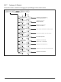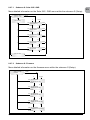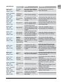
1
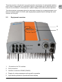
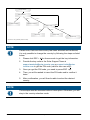
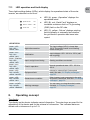
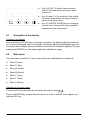
SOLIVIA 5.0 AP G3 TR Operation and installation manual This manual applies to solar inverters of type ●● EN SOLIVIA 5.0 AP G3 TR with the software version 1v0b10 The manual is subject to change. Please check our website at www.solar-inverter.com for the most up-to-date manual version. Delta Energy Systems (Germany) GmbH Tscheulinstraße 21 79331 Teningen Germany © Copyright – Delta Energy Systems (Germany) GmbH - All rights reserved. This manual accompanies our equipment for use by the end users. The technical instructions and illustrations contained in this manual are to be treated as confidential and no part may be reproduced without the prior written permission of Delta Energy Systems Service engineers and end users may not divulge the information contained herein or use this manual for purposes other than those strictly connected with correct use of the equipment. All information and specifications are subject to change without notice. Operation and installation manual SOLIVIA 5.0 AP G3 TR 3 4 Operation and installation manual SOLIVIA 5.0 AP G3 TR Table of Contents EN 1. About this manual . . . . . . . . . . . . . . . . . . . . . . . . . . . . . . . . . . . . . .7 1.1 Purpose of this manual . . . . . . . . . . . . . . . . . . . . . . . . . . . . . . . 7 1.2 Warnings and symbols . . . . . . . . . . . . . . . . . . . . . . . . . . . . . . . .7 2. Intended use . . . . . . . . . . . . . . . . . . . . . . . . . . . . . . . . . . . . . . . . .8 3. General safety instructions . . . . . . . . . . . . . . . . . . . . . . . . . . . . . . . . .8 4. Scope of delivery . . . . . . . . . . . . . . . . . . . . . . . . . . . . . . . . . . . . . . 9 5.System . . . . . . . . . . . . . . . . . . . . . . . . . . . . . . . . . . . . . . . . . . . .9 5.1 Data evaluation and communication . . . . . . . . . . . . . . . . . . . . . . . . 10 5.2 Technical structure of the solar inverter . . . . . . . . . . . . . . . . . . . . . . 10 5.3 Equipment overview . . . . . . . . . . . . . . . . . . . . . . . . . . . . . . . . 11 6.Installation . . . . . . . . . . . . . . . . . . . . . . . . . . . . . . . . . . . . . . . . . 12 7. Installation of equipment . . . . . . . . . . . . . . . . . . . . . . . . . . . . . . . . . 12 7.1 Installation location . . . . . . . . . . . . . . . . . . . . . . . . . . . . . . . . .12 7.2 Minimum requirements . . . . . . . . . . . . . . . . . . . . . . . . . . . . . . .13 7.3Maintenance . . . . . . . . . . . . . . . . . . . . . . . . . . . . . . . . . . . . 13 7.4Installation . . . . . . . . . . . . . . . . . . . . . . . . . . . . . . . . . . . . . 13 7.5 Ambient temperature . . . . . . . . . . . . . . . . . . . . . . . . . . . . . . . .14 7.6 Grid connection . . . . . . . . . . . . . . . . . . . . . . . . . . . . . . . . . . 15 7.7 Connection of PV modules . . . . . . . . . . . . . . . . . . . . . . . . . . . . .15 7.7.1 Output power over PV voltage . . . . . . . . . . . . . . . . . . . . . . 17 7.7.2 Efficiency . . . . . . . . . . . . . . . . . . . . . . . . . . . . . . . . . 17 7.8 Interface connection RS485 (EIA485) . . . . . . . . . . . . . . . . . . . . . . . 18 7.9 Electrical connection and operational start-up . . . . . . . . . . . . . . . . . . . 20 7.10 Setup / settings . . . . . . . . . . . . . . . . . . . . . . . . . . . . . . . . . . 21 7.11 LED operation and fault display . . . . . . . . . . . . . . . . . . . . . . . . . . 23 8. Operating concept . . . . . . . . . . . . . . . . . . . . . . . . . . . . . . . . . . . . . 23 8.1 8.2 Navigation in the display . . . . . . . . . . . . . . . . . . . . . . . . . . . . . . 24 Main menu . . . . . . . . . . . . . . . . . . . . . . . . . . . . . . . . . . . . . 24 8.2.1 Submenu N (Now) . . . . . . . . . . . . . . . . . . . . . . . . . . . . 26 8.2.2 Submenu D (Day) . . . . . . . . . . . . . . . . . . . . . . . . . . . . 27 8.2.3 Submenu W (Week) . . . . . . . . . . . . . . . . . . . . . . . . . . . 28 8.2.4 Submenu M (Month) . . . . . . . . . . . . . . . . . . . . . . . . . . . 28 8.2.5 Submenu Y (Year) . . . . . . . . . . . . . . . . . . . . . . . . . . . . 28 8.2.6 Submenu T (Total) . . . . . . . . . . . . . . . . . . . . . . . . . . . . 29 8.2.7 Submenu S (Setup) . . . . . . . . . . . . . . . . . . . . . . . . . . . 30 8.2.7.1 Submenu S: Solar ISO / GND . . . . . . . . . . . . . . . . . . . . . . . . . . . 31 8.2.7.2 Submenu S: Firmware . . . . . . . . . . . . . . . . . . . . . . . . . . . . . . . . 31 9. Diagnostics and data evaluation . . . . . . . . . . . . . . . . . . . . . . . . . . . . . 32 9.1 Malfunction rectification . . . . . . . . . . . . . . . . . . . . . . . . . . . . . . 32 9.2 Display messages . . . . . . . . . . . . . . . . . . . . . . . . . . . . . . . . . 32 Operation and installation manual SOLIVIA 5.0 AP G3 TR 5 10. Technical data . . . . . . . . . . . . . . . . . . . . . . . . . . . . . . . . . . . . . . . 34 11.Appendix . . . . . . . . . . . . . . . . . . . . . . . . . . . . . . . . . . . . . . . . . . 36 11.1 Connection examples . . . . . . . . . . . . . . . . . . . . . . . . . . . . . . . 36 11.2 Overview of connection diagrams . . . . . . . . . . . . . . . . . . . . . . . . . 38 12.Glossary . . . . . . . . . . . . . . . . . . . . . . . . . . . . . . . . . . . . . . . . . . 40 13. Certificates . . . . . . . . . . . . . . . . . . . . . . . . . . . . . . . . . . . . . . . . . 43 6 Operation and installation manual SOLIVIA 5.0 AP G3 TR 1. About this manual EN This manual allows you to become acquainted with the product. Observe the safety regulations applicable for each country. You can contribute to the durability and reliability of the product during its use by handling it carefully. These are basic prerequisites for optimum use of your product. 1.1 Purpose of this manual This manual is part of the product and is only valid for the SOLIVIA 5.0 AP G3 TR. Store the manual in a safe place. Read the manual carefully and thoroughly and follow the instructions contained therein. The manual contains important information on the installation and operation of the solar inverter. Take note of and follow the information on safe use (see „3. General safety instructions“, page 8). The installer and the operator must have access to this manual and must be familiar with the safety instructions. 1.2 Warnings and symbols The following section explains the warnings and symbols used in this manual. Danger Indicates a dangerous situation. An accident will lead to death or severe physical injuries. Warning Indicates a dangerous situation. An accident can lead to death or severe physical injuries. Caution Indicates a dangerous situation. An accident can lead to medium or light physical injuries. Attention Indicates a dangerous situation that can result in material damage. Note Contains general information on using the solar inverter. A note does not indicate dangerous situations. Operation and installation manual SOLIVIA 5.0 AP G3 TR 7 This symbol warns of a danger of electric shock due to the presence of high voltages. This symbol is a warning of general dangers. 2. Intended use The solar inverter connects a photovoltaic system to the public power grid. The solar inverter converts DC electricity into AC electricity, which is then fed into the public power grid. The solar inverter is intended for use in photovoltaic systems connected to a power grid. The solar inverter is not intended for mobile use. The solar inverter can be used indoors and in protected outdoor areas with ambient conditions according to IP65. The solar inverter may only be used within the specified power range and under the specified ambient conditions. The solar inverter contains monitoring devices, including an anti-islanding device. The solar inverter may only be used for the specified intended purpose. 3. General safety instructions Danger Danger of death from hazardous voltage Hazardous voltage is applied to the solar power inverter during operation. Hazardous voltage is still present 5 minutes after all power sources have been disconnected. ►► Never open the solar inverter. The solar inverter contains no components that are to be maintained or repaired by the operator or installer. Opening the cover will void the warranty. ●● Incorrect handling can lead to physical injuries and material damage! ●● The installation and commissioning work may be performed only by qualified electricians. ●● The solar inverter can be operated safely and normally only if it is installed and operated in accordance with this manual (see IEC 62109-5.3.3). Delta Energy Systems is not responsible for damage incurred by failure to comply with the installation and operating instructions in this manual. 8 Operation and installation manual SOLIVIA 5.0 AP G3 TR ●● The solar inverter contains no components that are to be maintained or repaired by the operator or installer. All repairs must be performed by Delta. ●● Observe all points in this installation and operation manual! ●● Before working on the solar inverter, you must disconnect it from the grid and the PV modules. ●● Do not disconnect any cables when the solar inverter is under load, as there is a risk of an arc fault. ●● To prevent lightning strikes, follow the regulations applicable in your country. ●● The surface of the solar inverter can get very hot. ●● The solar inverter is heavy (see „10. Technical data“, page 34). The solar inverter must always be lifted by two people. ●● The solar inverter has a high leakage current value (see „10. Technical data“, page 34). The ground wire MUST be connected before the start of operation. ●● Only equipment in accordance with SELV (EN 60950) may be connected to the RS485 interfaces. ●● Do not remove any warning signs that the manufacturer has installed on the solar inverter. ●● In order for IP65 protection to be granted, all used and unused connections must be sufficiently sealed. 4. Scope of delivery ●● SOLAR INVERTER SOLIVIA 5.0 AP G3 TR ●● Mounting plate ●● Operation and installation manual ●● AC connector 5. System The solar inverter converts direct current from the solar cells into alternating current. This enables you to feed your self-produced solar energy into the public grid. Thanks to efficient MPP tracking, maximum capacity utilization of the solar energy plant is ensured even in the case of cloudy sky conditions. The string concept means that PV modules are always connected in series (in a string) and/or that strings with the same voltage are connected in parallel to the solar inverter with the aim of significantly reducing the photovoltaic system’s cabling requirements. The fact that the modules are connected in strings also means that the photovoltaic system can be perfectly matched to the solar inverter’s input voltage range. Operation and installation manual SOLIVIA 5.0 AP G3 TR 9 EN 5.1 Data evaluation and communication The integrated data display, processing and communication of the device enables easy operation of the solar inverter. Monitoring of the operational status and signaling of operational failures are capable of being called up over the device display. The data interface enables the downloading of data which can be evaluated with a PC system and guarantees continuous recording of operating data. The best way of accessing this functionality is via the available accessories; comprehensive and seamless solar inverter monitoring is ensured. The data read-out over the integrated interface and the display is possible only in solar operation. 5.2 Technical structure of the solar inverter A galvanical isolation of the solar inverter from the grid is achieved through a DC/AC converter with an integrated high-frequency transformer. The photovoltaic voltage is adjusted so that the maximum power output of the PV modules is also achieved with varying solar irradiation levels and temperatures (MPP-Tracking). The MPP range of the solar inverter is between 150 V and 450 V. This facilitates the use of PV modules by a variety of manufacturers. Measures must be taken to ensure that the maximum open-circuit voltage of 540 VDC is never exceeded. Please note that the maximum open-circuit voltage will occur at the lowest temperatures anticipated. You will find more detailed information about temperature dependency in the data sheet of the PV modules. The device’s power consumption is kept to a minimum. The high-quality aluminum casing corresponds to protection class IP65 (water-jet-proof and dust-proof) and is protected against weathering processes by surface refinement. The cooling characteristic profile is designed so that operation of the inverter is possible with ambient temperatures from -25 °C to +60 °C. A cooling characteristic profile is used for the removal of the power dissipation caused through the voltage conversion. An internal temperature control protects the device against excessive temperatures in the interior of the solar inverter. In case of high ambient temperatures, the maximum transferable power is limited. The solar inverter is controlled by microcontrollers, which also implement interface communication and the monitoring of values and messages on the display. Two independent and redundant microcontrollers control the monitoring of the grid, which is consistent with the feed-in directives of your local utility company. This enables an installation of the solar inverter in the in-house electrical grid. Operator protection requirements are met by electrically isolating the grid from the PV module. The electrical isolation between the grid and the PV module is equivalent to basic insulation. Maximum operator protection is ensured by reinforced isolation between the grid, PV modules and accessible interfaces (display, RS485 interface). Relevant standards concerning electromagnetic compatibility (EMC) and safety are fulfilled. 10 Operation and installation manual SOLIVIA 5.0 AP G3 TR The solar inverter is functional in on-grid operation exclusively. An automated isolation point, which is approved by a certification agency, guarantees secure disconnection in case of circuit isolation or interruptions in power supply and avoids isolated operation. EN The disconnection equipment allows for automatic isolation for in-plant generation systems of nominal power ≤ 4.6 kVA, with single-phase parallel feed-in through the solar inverter into the grid. 5.3 Equipment overview (5) (4) (1) 1. (2) (3) Connections for PV modules 2. Grid connection 3. Interface connection RS485 (EIA485) 4. Display for status messages and keypad for operation 5. Light-emitting diodes for operational status display Operation and installation manual SOLIVIA 5.0 AP G3 TR 11 6. Installation Installation and commissioning must only be carried out by qualified electrical experts. The recommended local and national safety regulations should be complied with. To carry out an energy measurement, a meter must be attached between the grid feedin point and the solar inverter (in accordance with all local and national safety regulations). By means of the integrated anti-islanding protection, the function of the recommended section switch is fulfilled in accordance with all local and national safety regulations. For details, please see „10. Technical data“, page 34. Caution: The secondary short-circuit current rating is increased at the transfer connection point to the public electricity supply system by the nominal current of the connected solar inverter. 7. Installation of equipment 7.1 Installation location ●● Install the device on a non-flammable support base. ●● Avoid installation on resonating bodies (light construction walls etc.). ●● Installation is possible both indoors and in protected outdoor areas. ●● An increased ambient temperature can reduce the efficiency of the PV system. ●● The inverter may produce moderate noise during operation. Please select installation location with care. ●● Ensure legibility of the LEDs and the display (check read-off angle and installation height). ●● Although the unit is fitted with UV resistant components, direct exposure to sunlight should be avoided. ●● Despite having an IP65 enclosure and being certified in accordance with soiling category III, the unit must not be allowed to become heavily soiled. ●● Dusty conditions can impair the unit’s performance. NOTE According to the Australian / New Zealand Standard AS/NZS 5033:2005 (§ 3.1), PV arrays for installation on domestic dwellings in Australia or New Zealand shall not have maximum voltages greater than 600 V. 12 Operation and installation manual SOLIVIA 5.0 AP G3 TR 7.2 Minimum requirements EN ●● Free convection around the solar inverter must not be impaired. ●● For proper air circulation to dissipate heat, allow a clearance of approx. 10 cm to the side and approx. 50 cm above and below the unit. ●● The grid impedance requirement at the supply terminal is to be observed (cable length, cable cross-section). ●● The recommended installation position is to be adhered to (vertical). ●● Unused DC connectors and interfaces must be sealed airtight with sealing plugs to ensure protection class IP65 for the whole system (inverter & cables). 50 cm Wall 10 cm Wall 10 cm 50 cm 7.3 Maintenance Make sure that the device remains uncovered while in operation. To avoid the casing of the solar inverter becoming soiled, it should be cleaned periodically. User serviceable parts are not contained in the device. Under no circumstances should the solar inverter be opened! 7.4 Installation You should utilize the delivered mounting plate for problem-free installation of the solar inverter. Installation to the wall should be implemented with the proper screws. Mount the wall bracket so that the solar inverter only has to be simply attached. After that, the device is to be bolted on securely. Assembly instructions 1. Mount the mounting plate with appropriate screws (max. Ø 6mm) into at least four of the eight holes to fix the wall bracket in place. You can employ the mounting plate as a template for marking the positions of the boreholes. 2. As the solar inverter weighs 32 kg, it should be lifted out of the transport crate by at least two persons. Operation and installation manual SOLIVIA 5.0 AP G3 TR 13 3. Place the solar inverter onto the mounting plate with at least two persons. 4. Fasten the supplied mounting nuts and washers on the threaded bolt intended for securing the device. 5. Check that the solar inverter is securely sealed. 200 320 Mounting plate 12 38 90 2.5 Ø1 12 6.5 Locking screw 7.5 Locking screw 150 319.5 410 ± 0.5 Ambient temperature The solar inverter can be operated in an ambient temperature between -25°C to +60°C. The following diagram illustrates how the power supplied by the solar inverter is reduced automatically in accordance with ambient temperature. The device should be installed in a well-ventilated, cool and dry location. 6000 W 5000 W 4000 W 3000 W 2000 W 1000 W 0W 0 °C 14 10 °C 20 °C 30 °C 40 °C 50 °C 60 °C 70 °C 80 °C Operation and installation manual SOLIVIA 5.0 AP G3 TR 7.6 Grid connection The grid (AC output) is connected over a Wieland RST25i3S AC connector. You can find the correct allocation on the screw-type terminal connection of the connector. The solar inverter must be connected to the grid over a three-core line (L, N, PE). The connected AC line must be switched potential-free before the disconnection or the insertion of the AC connector. The connection to the Wieland AC connector must be made with a flexible line and a conductor cross section of 4.0 mm². An automatic circuit breaker is to be provided in the line L upstream of every device, with a nominal current of 32 A and tripping characteristic type B or C (please refer to your local country installation requirements and regulations for correct tripping characteristic type). In addition, attention is to be paid to the selectivity of the fuse unit attached upstream of the automatic circuit breaker. The solar inverter must be grounded via the AC connector’s PE conductor. To do this, connect the PE conductor to the designated terminal. If you wish to integrate more than one inverter into the installation, please proceed as illustrated in the drawings in the appendix. Please note the cable length and the cable cross-section, due to the risk of undesirable temperature rise and power losses. The AC connector is protected from unintentional disconnection by a clip mechanism which can be released with a screwdriver. 7.7 Connection of PV modules Before the photovoltaic system is connected, the polarity of the PV voltage at the MultiContact connectors must be checked to ensure that it is correct. The connection of the PV module is implemented using Multi-Contact MC4 connectors, where the DC negative pole is located on the connector upper row and the DC positive pole on the connector lower row. The connectors are coded to prevent you from accidentally plugging them into the wrong terminal. Please ensure the following at all times: ●● That there is never any risk of anyone coming into contact with the solar inverter connectionterminals, due to the risk of dangerous voltages across them. ●● That under no circumstances are the PV modules to be disconnected from the solar inverter under load. If a disconnection should be necessary, first switch the grid off so that the solar inverter cannot absorb any further power. Next, open the upstream DC disconnector. The maximum input voltage of the solar inverter is 540 V. The maximum current load of each individual Multi-Contact MC4 connector is 18 A. Operation and installation manual SOLIVIA 5.0 AP G3 TR 15 EN The solar inverter has an insulation and grounding monitoring on the DC side. The options can be configured in the Setup menu “S -> Solar ISO / GND” (see „8.2.7.1 Submenu S: Solar ISO / GND“, page 31). The insulation monitoring has two modes: ●● ISO-ON-Error (the solar inverter is disconnected from the grid in the event of an insulation fault) ●● ISO-ON-Warning (the solar inverter indicates the fault but is not disconnected from the grid). Deltas solar inverters are factory-set to ISO-ON-Warning mode on delivery. The grounding monitoring has two modes: ●● PV+ grounding (grounding monitoring of the positive pole of the PV generator) ●● PV- grounding (grounding monitoring of the negative pole of the PV generator). In these modes the solar inverter remains in feed-in operation and will not be disconnected from the grid in case of a fault. The error message “PV+ grounding fault” or “PVgrounding fault” will appear on the display. If you need to connect the positive or negative pole of the PV system to meet requirements set out by the module manufacturer, you can do this. Earth continuity must be implemented close to the inverter. We suggest using Deltas grounding kit “SOLIVIA Grounding Kit MC4” (EOE99000275). The grounding connection is monitored and should be configured in the Setup menu (see „8.2.7 Submenu S (Setup)“, page 30). Alternatively, it is possible to turn off the insulation- and grounding monitoring: ●● ISO / GND OFF. Required cable coupler types for DC cable connection to inverter: WIRE SIZE FEMALE CABLE WIRE SIZE 4.0 MM2 2 COUPLER 2.5 MM CABLE 6.0 MM² POLARITY (AWG 14) COUPLER (AWG 12-10) Plus ●● ●● coupler Minus ●● coupler Plus ●● ●● coupler Minus ●● coupler 16 MALE CABLE COUPLER ●● ●● MULTI-CONTACT ORDER NUMBER 32.0010P0001-UR 32.0012P0001-UR 32.0011P0001-UR 32.0013P0001-UR 32.0014P0001-UR 32.0016P0001-UR 32.0015P0001-UR 32.0017P0001-UR Operation and installation manual SOLIVIA 5.0 AP G3 TR 7.7.1 Output power over PV voltage EN 6000 W 5000 W 4000 W 3000 W 2000 W 1000 W 0 7.7.2 1 5 0 VDC 2 0 0 VDC 2 5 0 VDC 3 0 0 VDC 3 5 0 VDC 4 0 0 VDC 4 5 0 VDC Efficiency The best efficiency of the solar inverter is obtained at input voltages >250 V. 100 % 95 % 90 % 85 % 80 % 75 % 70 % 65 % 60 % 50 W 500 W 1000 W SOLIVIA 5.0 - 150 V 1500 W 2000 W 2500 W SOLIVIA 5.0 - 250 V Operation and installation manual SOLIVIA 5.0 AP G3 TR 3000 W 3500 W SOLIVIA 5.0 - 350 V 4000 W 4500 W 5000 W SOLIVIA 5.0 - 450 V 17 7.8 Interface connection RS485 (EIA485) The interfaces not used must always be closed off. In case of utilization of an interface, only the counterpart fitting on the interface connector is to be employed. Mating connector supplier HARTING Deutschland GmbH & Co. KG (P.O. 2451, 32381 Minden; Germany; www.harting.com). Order designation: ●● 09 45 145 1510, Cable Manager Blue IP67 Push-Pull Data Plug ●● 09 45 145 1500, Cable Manager White IP67 Push-Pull Data Plug - - ~ ~ ~ ~ RS485 (EIA485) terminating resistor 230 V - House connection line RS485 (EIA485) - Connection Datalogger Connector pin assignment RS485 (EIA485) Pin 8 Top View 18 1 1 2 3 4 5 6 7 8 Reserved Reserved Reserved GND (RS485) Reserved RX_B (RS485) TX_A (RS485) Reserved Operation and installation manual SOLIVIA 5.0 AP G3 TR When several devices are connected in series and the total length of the data line measures 2 m or more, the following option is available for terminating the RS485 (EIA485) interface: EN +5V Reserved 0R TX_A Pin 7 RX_B Pin 6 0R 100 ... 150 Ohm, 0,25W Reserved GND Anti-islanding protection Power controller Communication Operating- and system control DC String A String C String D DC DC MPPTracker - Isolation - - - DC-Bus String B Booster - Public grid ~ AC DC Solar inverter Operation and installation manual SOLIVIA 5.0 AP G3 TR 19 7.9 Electrical connection and operational start-up The electrical connection is utilized on this solar inverter using the connector contacts which are attached to the casing. In no case must the device be opened! In order to connect the device electrically, the following procedures must be followed: 1. DC connection: First, connect the PV module strings to the DC disconnector (not included in the scope of delivery). 2. Connect the DC disconnector to the solar inverter (ensure correct polarity). 3. AC connection: Please install the Wieland AC mating connector to the AC output cable and then put the AC connector to the solar inverter. Please make sure, that the sleeve nut is properly fixed and tighten. 4. Before switching on the power, check all feeders and connections one last time. 5. Close the DC disconnector. 6. Close the circuit breaker on the AC output side. 7. In case of sufficient PV voltage (UPV > 150 V), the device now goes into the start-up mode. 8. In case of a new installation the time and date have to be set in sub-menu S (Setup) (see „8.2.7 Submenu S (Setup)“, page 30). NOTE To ensure protection conforming to IP65 all unused connections and interfaces must be closed using the provided sealing plugs. 20 Operation and installation manual SOLIVIA 5.0 AP G3 TR 7.10 Setup / settings EN The default display language for solar inverters leaving the Delta factory is set to English. After connecting to correct DC voltage and running through self-test, you will be asked to specify the network ID and to select the desired country (countries available: India, Australia, Australia PL 4.601) and Australia PL 4.991)). The selection has to be confirmed another time by the user. Once confirmed, the network ID and the country selection are stored to the controller memory – and the solar inverter is ready for operation. NOTE Please note that the enter keys on the display are locked, if there is no input entry within 5 minutes. The following display message appears: “Block selection”. To unlock the enter keys, you need to switch off the DC voltage and then switch it on again (see „9.2 Display messages“, page 32). 1) In certain states in Australia, power limitation is required. ●● With power limitation (PL), the output (AC) power of SOLIVIA 5.0 AP G3 TR will be as followed : Power limitation setting AU PL 4.60 -> Max. power: 4600 W Power limitation setting AU PL 4.99 -> Max. power: 4990 W ●● To activate power limitation, please select dedicated country “Australia PL4.60” respectively “Australia PL4.99“ (Installed settings are password protected): Select unit ID = [1] & press <ENTER> key Select country = [Australia PL4.60] or [Australia PL4.99] & press <ENTER> key Confirm country selection by pressing <ENTER> key ●● One of the following labels that are enclosed in the box of the inverter MUST be sticked next to the model label: For Australia PL4.60 This product has been power limited at maximal output power of: 4.60 kW ●● For Australia PL4.99 This product has been power limited at maximal output power of: 4.99 kW To check if power limitation has been activated, please go to the menu S (Setup) and press the „UP“ or „DOWN“ buttons to find the following display message: Down Up S -> Firmware AU PL 4.60 Down Up S -> Firmware AU PL 4.99 Operation and installation manual SOLIVIA 5.0 AP G3 TR 21 Country selection Enter network ID Up * Increase network ID Down * ENTER * Decrease network ID ESC * Select country Up * Next country Down * ENTER * Country before Normal mode * Timeout if no key is pressed (within 5 minutes) NOTE Please note, that once the country has been selected and confirmed, it is only possible to change the country by following the steps as listed below: 1. Please click ESC + for few seconds to get the key information. 2. Provide the key code to the Solar Support Team at [email protected] or [email protected] to get the PIN code (valid for one use only!). 3. Once you get the PIN code, you need to press ESC + . 4. Then, you will be asked to insert the PIN code and to confirm it twice. 5. After confirmation, you will then be able to select the desired country. NOTE These steps must be executed without interruption. Otherwise, you will stay in the country selection mode. 22 Operation and installation manual SOLIVIA 5.0 AP G3 TR 7.11 LED operation and fault display EN Three light-emitting diodes (LEDs), which display the operational state of the solar inverter, are attached on the front: Operation (A) Earth Fault (B) Failure LED STATUS green: <off> red: <off> yellow: <off> green: <on> red: <on> yellow: <on> green: <flashes> red: <off> yellow: <off> green: <on> red: <off> yellow: <off> green: <off> red: <on/off> yellow: <on/off> green: <off> red: <on/off> yellow: <on> green: <on/off> red: <on/off> yellow: <flashes> 8. ●● LED (A), green: „Operation“ displays the operational state. ●● LED (B), red: „Earth Fault“ displays an insulation resistance fault or PV grounding (GND) fault on the DC side. ●● LED (C), yellow: „Failure“ displays existing faults internally or externally and whether the grid feed-in operation has been interrupted. (C) OPERATIONAL STATE Night disconnection. EXPLANATION The input voltage (UPV) is lower than 100 V. The solar inverter is not feeding power to the grid. Initialization Input voltages: UPV: 100 V to 150 V (self test ongoing). Input- and grid monitoring. Starting conditions are tested. Feed-in operation. Normal operational state: UPV: 150 V to 450 V. Equipment fault. General error condition. Warning message. Internal or external fault (interrupted feed). See also „9.2 Display messages“, page 32. Solar inverter is not connected to the grid. No power is delivered. See also „9.2 Display messages“, page 32. You can carry on using the solar inverter. See also „9.2 Display messages“, page 32. Operating concept The display The display on the device indicates varied information. The enter keys are used for the adjustment of the device and for the retrieval of information. The indicated data can deviate with a tolerance of up to 5 %. Operation and installation manual SOLIVIA 5.0 AP G3 TR 23 (A) (B) (C) ESC 8.1 ●● Key (A), ESC: To switch from the menu items to the main menu and to exit each sub-menu. ●● Key (B) and (C): For scrolling in the individual menu items and/or carrying out adjustments in the setup menu. ●● Key (D), ENTER: ENTER key for changing into the menu levels and for input acknowledgement in the setup menu. (D) Navigation in the display Lighting of the display After pressing the ENTER key in automatic operation, the display lighting is switched on. If no key is pressed within 30 seconds, the display lighting automatically goes out. The setup menu enables selection between continuous or automatic lighting. Through pressing the ENTER key, the display lighting is switched on again. 8.2 Main menu The main menu consists of 7 menu items which are subdivided into submenus: ●● Menu N (Now) ●● Menu D (Day) ●● Menu W (Week) ●● Menu M (Month) ●● Menu Y (Year) ●● Menu T (Total) ●● Menu S (Setup) Handling of the menu items: You can scroll the main menu by activating the selector keys . Press the ENTER key to select the submenus. In order to exit the menus again, activate the ESC key. 24 Operation and installation manual SOLIVIA 5.0 AP G3 TR EN User menu 2 Up to 1 Menu N - Now (act data) ESC ENTER Down Submenu N - Now Up Menu D - Day statistic Down ESC ENTER Submenu D - Day Up Menu W - Week statistic ESC ENTER Down Submenu W - Week Up Menu M - Month statistic ESC Submenu M - Month ENTER Down Up Menu Y - Year statistic ESC ENTER Down Up Menu T - Total statistic ESC Submenu Y - Year Submenu T - Total ENTER Down Up Menu S - Setup inverter Down to 2 ESC ENTER 1 Submenu S - Setup Remarks: ESC in main menu jumps to first entry of corresponding sub menu Operation and installation manual SOLIVIA 5.0 AP G3 TR 25 8.2.1 Submenu N (Now) This menu item displays the active values. Main menu N - Now actual data ENTER Submenu N - Now 2 ESC N -> AC-Power Value (W) Down ESC ESC ESC ESC Display of the active PV cell voltage input 2 Up Display of the active PV cell current input 2 Up Display of the current time Up N -> Date (WD.DD.MM.YYYY) Down to 2 26 Up N -> Time (HH:MM:SS) Down ESC Display of the active PV cell current input 1 N -> PV2-Current Value (A) Down ESC Up N -> PV2-Voltage Value (V) Down ESC Display of the active PV cell voltage input 1 N -> PV1-Current Value (A) Down ESC Display of the active mains frequency Up N -> PV1-Voltage Value (V) Down Display of the active output current Up N -> AC-Frequency Value (Hz) Down Display of the active output voltage Up N -> AC-Current Value (A) Down Display of the active output power Up N -> AC-Voltage Value (V) Down ESC Up to 1 1 Display of current day of the week and date Remarks: ESC in main menu N jumps to first entry of sub menu N Operation and installation manual SOLIVIA 5.0 AP G3 TR 8.2.2 Submenu D (Day) EN This menu item displays the daily values for the grid feed. Main menu D - Day statistic ENTER Submenu D - Day 2 ESC D -> Energy Value (Wh) Down ESC ESC ESC Display of the daily max. output voltage Up D -> AC-Volt-Min Value (V) Down Display of the daily maximum output power Up D -> AC-Volt-Max Value (V) Down ESC Display of the daily revenue Up D -> AC-Power-Max Value (W) Down Display of the daily energy gain Up D -> AC-Revenue Value (AUD) Down ESC Up to 1 Display of the daily min. output voltage Up D -> AC-Curr-Max Value (A) Display of the daily maximum output current Down ESC Up D -> AC-Freq.-Max Value (Hz) Down ESC ESC Up D -> AC-Freq.-Min Value (Hz) Down Display of the daily maximum output frequency Display of the daily minimum output frequency Up D -> Runtime Value (Min) Down to 2 Operation and installation manual SOLIVIA 5.0 AP G3 TR 1 Display of the daily operating time of the solar inverter Remarks: ESC in main menu D jumps to first entry of sub menu D 27 8.2.3 Submenu W (Week) This menu item displays the average values of the current week. Main menu W - Week statistic ENTER Submenu W - Week 2 ESC Up to 1 W -> Energy Value (kWh) Display of the weekly energy gain Down Up ESC W -> AC-Revenue Value (AUD) Display of the weekly revenue Down Up ESC W -> Runtime Value (h) Down to 2 8.2.4 1 Display of the weekly operating time of the solar inverter Remarks: ESC in main menu W jumps to first entry of sub menu W Submenu M (Month) This menu item displays the average values of the current month. Main menu M - Month statistic ENTER Submenu M - Month 2 ESC Up to 1 M -> Energy Value (kWh) Display of the monthly energy gain Down Up ESC M -> AC-Revenue Value (AUD) Display of the monthly revenue Down Up ESC M -> Runtime Value (h) Down to 2 8.2.5 Display of the monthly operating time of the solar inverter Remarks: ESC in main menu M jumps to first entry of sub menu M 1 Submenu Y (Year) This menu item displays the average values of the current year. Main menu Y - Year statistic ENTER Submenu Y - Year 2 ESC Up to 1 Y -> Energy Value (kWh) Display of the annual energy gain Down Up ESC Y -> AC-Revenue Value (AUD) Display of the annual revenue Down Up ESC Y -> Runtime Value (h) Down to 2 28 1 Display of the annual operating time of the solar inverter Remarks: ESC in main menu Y jumps to first entry of sub menu Y Operation and installation manual SOLIVIA 5.0 AP G3 TR 8.2.6 Submenu T (Total) EN This menu item shows cumulated and maximum/minimum values since first use. Main menu T - Total statistic ENTER Submenu T - Total 2 ESC T -> Energy Value (kWh) Down ESC ESC ESC ESC Display of the max. PV cell voltage input 2 Up Display of the max. PV cell power input 2 Up T -> Runtime Value (Min) Down to 2 Display of the max. PV cell current input 2 Up T -> PV2-Pow. Max Value (W) Down Display of the max. PV cell power input 1 Up T -> PV2-Cur. Max Value (A) Down ESC Display of the max. PV cell current input 1 Up T -> PV2-Vol. Max Value (V) Down ESC Up T -> PV1-Pow. Max Value (W) Down ESC Display of the max. PV cell voltage input 1 T -> PV1-Cur. Max Value (A) Down Display of the total revenue Up T -> PV1-Vol. Max Value (V) Down Display of the total energy gain Up T -> Revenue Value (AUD) Down ESC Up to 1 1 Operation and installation manual SOLIVIA 5.0 AP G3 TR Display of the total operating time of the solar inverter Remarks: ESC in main menu T jumps to first entry of sub menu T 29 8.2.7 Submenu S (Setup) This menu item is used for changing the presettings of the solar inverter. Main menu S - Setup ENTER Submenu S - Setup 2 ESC S -> LCD-Contrast 0 ... 9 Down ESC ESC Up ISO / GND Setup Menu Up Adjustment of the baud rate between 2400 ... 38400 Baud Up Adjustment of the internal clock Up Adjustment of current day of the week and date Up S -> Firmware Down to 2 30 Input of the ID number of the solar inverter S -> Date (WD.DD.MM.YYYY) Down Entry of feed-in remuneration in AUD per kWh Up S -> Time (HH:MM:SS) Down ESC Up S -> Baudrate 2400 ... 38400 Down ESC Selection of the start menu on restart of the device S -> Solar ISO / GND Down ESC Up S -> ID-Number 001 ... 254 Down ESC Adjustment of the LCD background lighting S -> Cash per kWh Value (AUD) xx,xx Down ESC Up S -> Menu-Mode Now ... Setup Down ESC Adjustment of the brightness of the LCD display between 0 ... 9 S -> LCD-Backlight Auto / On Down ESC Up to 1 Adjustment of the firmware 1 Operation and installation manual SOLIVIA 5.0 AP G3 TR 8.2.7.1 Submenu S: Solar ISO / GND More detailed information on the Solar ISO / GND menu within the submenu S (Setup). Submenu Setup Solar ISO / GND ENTER 5 Use old setting ESC Up to 6 S -> Solar ISO / GND ISO ON-Warning ENTER Down Up ESC ENTER S -> Solar ISO / GND ISO ON-Failure Down Up S -> Solar ISO / GND ISO GND-OFF ESC ENTER Down Up S -> Solar ISO / GND PV+ grounded ESC ENTER Down Up ESC S -> Solar ISO / GND PV- grounded Down to 5 ENTER 6 Use new value 8.2.7.2 Submenu S: Firmware More detailed information on the firmware menu within the submenu S (Setup). Submenu Setup Firmware ENTER 4 ESC Up to 3 S -> Firmware AC-Ctrl maj.min.bug Down Up ESC S -> Firmware DC-Ctrl maj.min.bug Down Up ESC S -> Firmware SC-Ctrl maj.min.bug Down Up ESC S -> Firmware Display-Ctrl maj.min.bug Down to 4 ESC 3 S -> Firmware IT GMon-Ctrl maj.min.bug Down to 4 3 Operation and installation manual SOLIVIA 5.0 AP G3 TR 31 EN 9. Diagnostics and data evaluation 9.1 Malfunction rectification The solar inverter is provided with an automatic diagnostics system which independently identifies certain faults and which can make them visible on the display. Troubleshooting in the field In principle, it is always worth attempting a reset by reinitializing the solar inverter whenever an error message appears on the display. To reset the device, proceed as follows: 1. Isolate the solar inverter from the grid (open automatic circuit breaker). 2. Switch off the DC disconnector. 3. Wait: approx. 1 minute. 4. Switch DC disconnector back on. 5. Switch in grid (close automatic circuit breaker). (In the field, the first step is to scan for potential fault causes that could be picked up by the solar inverter and result in tripping.) Various key parameters can be scanned via the display, thereby enabling conclusions to be drawn about potential fault causes. Current values in the N menu AC Voltage -> Display of current output voltage -> Voltage limiting values AC Frequency -> Display of current grid frequency -> Frequency limiting values Solar Voltage -> Display of current PV cell voltage ->Switch-in threshold 9.2 Display messages LED STATUS green: <on> red: <on> yellow: <on> green: <off> red: <off> yellow: <on> green: <off> red: <off> yellow: <on> 32 DISPLAY MESSAGE CAUSE ELIMINATION Display communication faulty. If the fault persists after the device has been reset, please inform your service technician. Grid frequency overshooAC frequency Check the grid frequency via the ting or undershooting failure display in the N menu. specified limit range. Check the grid voltage via the Grid voltage overshooting display in the N menu. AC voltage or undershooting specified failure If no voltage present, check grid limit range. automatic circuit breaker. Operation and installation manual SOLIVIA 5.0 AP G3 TR LED STATUS green: <off> red: <off> yellow: <on> green: <flashes> red: <off> yellow: <off> green: <off> red: <off> yellow: <on> green: <off> red: <off> yellow: <on> DISPLAY MESSAGE CAUSE AC relay failure One of the anti-islanding The solar inverter is defective. protection output relays is Return the device. faulty / defective. Calibration ongoing Check internal settings. DC injection failure Error # 301 green: <off> red: <off> yellow: <on> Error # 302 green: <off> red: <on> yellow: <off> Error # 506 Error # 508 green: <on> red: <on> yellow: <off> Isolation start-up warning Isolation running warning green: <on> red: <on> yellow: <off> PV+ grounding fault PV- grounding fault green: <off> red: <off> yellow: <on> green: <on> red: <on> yellow: <on> green: <flashes> red: <off> yellow: <off> green: <flashes> red: <off> yellow: <off> green: <flashes> red: <off> yellow: <off> EN ELIMINATION Normal function before input mode. DC component of inputIf the fault persists after the device side alternating current is has been reset, please inform your too high. service technician. If the fault persists after the device Internal communication has been reset, please inform your error or hardware fault. service technician. The device trips and reverts to grid input mode Check the installation site (no once the temperature has direct sunlight, air circulation). dropped. Isolation resistance fault on the DC side during Check the isolation resistance on start-up phase (# 508) or the DC side of the PV modules. running phase (# 506). Isolation resistance fault on the DC side during start-up phase or running phase. You must check the isolation resistance on the DC side of the PV modules. Solar inverter is still feeding! Check that the GND connection has been made correctly and/or check the fuse in the grounding path. Change the fuse if necessary. The solar inverter remains in feedin operation. If the fault persists after the device Revision Versions of hard- and softhas been reset, please inform your error ware are not compatible. service technician. The first time the solar inverter is Self test Initialization of solar inver- started up: ongoing ter on start-up. Normal function with a PV cell voltage of between 100 V and 150 V. Insufficient insolation (dawn/twiPV power too light). Insufficient input power. low Check the PV cell voltage via the display in the N menu. Insufficient insolation. PV voltage PV generator voltage betCheck the PV cell voltage via the too low ween 100 V and 150 V. display in the N menu. Checks grid voltage and Synchronize grid frequency for grid Normal function before input mode. to AC input mode. Connection PV+ (PV-) to GND is interrupted or wrong pole is connected to GND. Operation and installation manual SOLIVIA 5.0 AP G3 TR 33 DISPLAY MESSAGE LED STATUS green: <on> Varistor red: <off> warning yellow: <flashes> green: <off> red: <off> yellow: <on> Block selection CAUSE ELIMINATION Although you can, in theory, carry on using the solar inverter, the Internal varistor at the DC varistors should be replaced at input is defective. the earliest opportunity. This will involve returning the device. Enter keys on the display To unlock the enter keys, you need are locked, if there is to switch off the DC voltage and no input entry within 5 then switch it on again. minutes. NOTE Please follow the instructions above before contacting your service technician! 10. Technical data INPUT (DC) AUSTRALIA Max. recommended PV power INDIA 6000 WP Nominal power 5500 W Voltage range 125 ... 540 V Full power MPP range 150 ... 450 V Nominal current 17.2 A Max. current OUTPUT (AC) 32 A AUSTRALIA Max. power 5240 W 1), 2) Nominal power Voltage range 5000 W 2) 210 ... 264 V Max. current 184 ... 264.5 V 27.2 A Nominal current 22 A Nominal frequency Frequency range INDIA 50 Hz 48 ... 52 Hz 47.3 ... 52.7 Hz Power factor > 0.99 @ nominal power Total harmonic distortion THD) < 4 % @ nominal power 34 Operation and installation manual SOLIVIA 5.0 AP G3 TR GENERAL SPECIFICATION AUSTRALIA INDIA Model name Part number Delta EOE46010301 Max. efficiency 95.6 % Efficiency EU 94.6 % Operating temperature -25 ... +60 °C Storage temperature -25 ... +80 °C Humidity 0 ... 98 % Max. operating altitude MECHANICAL DESIGN 2000 m (above sea level) AUSTRALIA INDIA Size (L x W x D) 510 x 410 x 180 mm Weight 32 kg Cooling Convection AC connector Wieland RST25i3S DC connector 4 pairs of Multi-Contact MC4 Communication interfaces 2 x RJ45 / RS485 Display STANDARDS / DIRECTIVES 3 LEDs, 2-line LCD AUSTRALIA INDIA Protection degree IP65 Safety class I Configurable trip parameters Yes Insulation monitoring Yes Overload behavior EN SOLIVIA 5.0 AP G3 TR Current limitation; power limitation Anti-islanding protection / Grid regulation AS 4777.2; AS 4777.3; IEC 60255.5 VDE 0126-1-1 EMC AS 4777.1; AS 4777.2; AS 4777.3; EN 61000-6-2; IEC / EN 61000-6-3 IEC / EN 61000-6-2; IEC / EN 61000-6-3 Safety AS/NZS 60950.1; AS/NZS 3100; AS 4777.2; AS 4777.3 IEC 62103; EN 50178; IEC 62109-1, IEC 62109-2 1) The maximum AC power value indicates the power an inverter might be able to deliver. However, such a maximum AC power may not necessarily be achieved. 2) In certain states in Australia, power limitation is required. With power limitation, the output (AC) power of SOLIVIA 5.0 AP G3 TR will be as followed: Power limitation setting AU PL 4.60 -> Max power: 4600 W; Nominal power: 4250 W Power limitation setting AU PL 4.99 -> Max. power 4990 W; Nominal power: 4600 W Operation and installation manual SOLIVIA 5.0 AP G3 TR 35 11. Appendix 11.1 Connection examples Individual in-plant generation system in parallel operation without isolated operation possibility, single-phase feed with anti-islanding protection. Low-voltage network ~ 400 / 220 V Low-voltage network ~ 400 / 230 V House connection line House connection box VNB Owner boundary Customer Measurement unit (1) Meter for power consumption (2) Meter for power feed-in with back stop in each case Z (2) Z (1) Remark: A meter can also be employed which registers both energy directions separately ~ 400 / 220 V ~ 400 / 230 V Electric circuit distributor Switching equipment Anti-islanding protection with voltage and frequency monitoring, as well as network impedance measurement Consumer equipment of the customer Photovoltaic generator with power inverter max. 4.6 kVA 36 ~ = Short-circuit protection Overload protection Operation and installation manual SOLIVIA 5.0 AP G3 TR Individual in-plant generation system in parallel operation without isolated operation possibility, single-phase feed with anti-islanding protection, separate feed. Low-voltage network ~ 400 / 220 V Low-voltage network ~ 400 / 230 V House connection line House connection box VNB Owner boundary Customer Z (3) Z (2) Z (1) Remark: A meter can also be employed which registers both energy directions separately. (3) Meter for power take-off of the customer system ~ 400 / 220 V ~ 400 / 230 V Electric circuit distributor Switching equipment Anti-islanding protection with voltage and frequency monitoring, as well as network impedance measurement Consumer equipment of the customer Photovoltaic generator with power inverter max. 4.6 kVA Measurement unit (1) Meter for power consumption (2) Meter for power feed-in with back stop in each case ~ = Operation and installation manual SOLIVIA 5.0 AP G3 TR Short-circuit protection Overload protection 37 EN 11.2 Overview of connection diagrams PV generator PV generator - + - DC terminal strip + Meter for power consumption DC disconnector - Solivia 5.0 - + Z ~ Consumer equipment 3 Automatic circuit breaker type B 32 A 3 PV generator Selective main line circuit breaker Meter for power feed-in 3 Z - Customer Meter for kWh power consumption House connection box 3 3 House connection line PV generator DC disconnector 38 3 Solivia 5.0 DC disconnector - Solivia 5.0 ~ ~ Automatic circuit breaker type B 32 A Automatic circuit breaker type B 32 A Meter for kWh power feed-in Operation and installation manual SOLIVIA 5.0 AP G3 TR 2 1 ... 3 EN n PV generator DC disconnector Solivia 5.0 L1 - - N ~ PE L2 N ~ PE L3 N ~ PE Fuse L1 L2 L3 N PE Operation and installation manual SOLIVIA 5.0 AP G3 TR 39 12. Glossary AC Abbreviation for „Alternating Current“. Anti-islanding protection This is a unit for grid monitoring with assigned switching elements (anti-islanding protection) and is an automatic isolation point for small power generation systems (to 30 kWp). CE With the CE identification code, the manufacturer confirms the conformity of the product with the valid EC Guideline and compliance with the significant requirements stipulated therein. DC Abbreviation for „Direct Current“. EMC The Electro-Magnetic Compatibility (EMC) concerns the technical and legal basics of the mutual influencing of electrical devices through electromagnetic fields caused by them in electrical engineering. Initialization Under initialization (cf. English to initialize) is understood the part of the loading process of a program, in which the storage space required for the execution (e.g. variable, code, buffers ...) for the program is reserved and is filled with initial values. Local utility company By local utility company is meant a company which generates electrical energy and distributes it over the public grid. MPP The Maximum Power Point is the point of the current-voltage diagram of a PV cell at which the largest power can be tapped off, i.e. the point at which the product of current and voltage has its maximum value. 40 Operation and installation manual SOLIVIA 5.0 AP G3 TR Nominal power Nominal power is the maximum permissible continuous power output indicated by the manufacturer for a device or a system. Usually the device is also optimized so that the efficiency is at its maximum in case of operation with nominal power. Nominal current Nominal current is the absorbed current in case of electrical devices if the device is supplied with the nominal voltage and yields its nominal power. PE In electric systems and cables a protective earth conductor is frequently employed. This is also called grounding wire, protective grounding device, soil, grounding or PE (English „protective earth“). Photovoltaics (abbr.: PV) The conversion of PV energy into electrical energy. The name is composed of the component parts: Photos - the Greek word for light - and Volta - after Alessandro Volta, a pioneer in electrical research. Potential isolation No conductive connection between two component parts. Power dissipation Power dissipation is designated as the difference between absorbed power and power of a device or process yielded. Power dissipation is released mainly as heat. PV cell PV cells are large-surface photodiodes which convert light energy (generally sunlight) into electrical energy. This comes about by utilization of the photoelectric effect (photovoltaics). PV generator System comprising a number of PV modules. Operation and installation manual SOLIVIA 5.0 AP G3 TR 41 EN PV module Part of a PV generator; converts PV energy into electrical energy. RJ45 Abbreviation for standardized eight-pole electrical connector connection. RJ stands for Registered Jack (standardized socket). RS485 (EIA485) Differential voltage interface on which the genuine signal is transmitted on one core and the negated (or negative) signal on the other core. Separate grid system Energy supply equipment which is completely independent of an interconnected grid. Solar inverter is an electrical device which converts DC direct voltage into AC voltage and/or direct current into alternating current. String Designates a group of electrical PV modules switched in series. String solar inverter (solar inverter concept) The PV generator is divided up into individual strings which feed into the grid over their own string solar inverters in each case. In this way, the installation is considerably facilitated and the gain decrease, which can arise from the installation or from different shading conditions of the PV modules, is considerably reduced. TAB (2000) The TAB 2000 are the technical regulations governing connection to the low-voltage grid operated by distribution system operators in Germany. These Technischen Anschlussbestimmungen or TAB for short have been in force since the year 2000. They define the requirements imposed by DSOs on the electrical systems operated by the end customers of utility companies. 42 Operation and installation manual SOLIVIA 5.0 AP G3 TR 13. Certificates Supplier’s declaration of conformity For compliance levels 1, 2 and 3 in Australia As required by notices under: section 182 of the Australian Radiocommunications Act 1992. Instructions for completion This completed form remains with the supplier as part of the documentation required for the compliance records. Do not return this form to the ACMA. Supplier’s details Qualsure Consultants ACMA supplier code number N136 (AGENT) of 18 Hood Street Rosedale Vic. Product details Product description – brand name, type, model, lot, batch or serial number (if available) Delta Brand Name Model Number SOLIVIA5.0APG3 Description Solar Inverter Compliance with Radiocommunications (Electromagnetic Compatibility) Standard 2008 The above mentioned product complies with the requirements of the Radiocommunications (Electromagnetic Compatibility) Standard 2008. Evidence of compliance is demonstrated by test reports to the following applicable standards. Applicable standards Standard title, number and, if applicable, number of the test report Standard AS/NZS CISPR 11:2004 Test Report Number 07TH0223-VDE0126-1 Declaration I hereby declare that the product mentioned above complies with the requirements of the Radiocommunications (Electromagnetic Compatibility) Standard 2008. All products supplied under this declaration will be identical to the product identified above. Gordon Slimmon Director 2 Feb. 11 QUALSURE CONSULTANTS A division of Blulen Pty Ltd (ACN 090 692 354) Registered Office 18 Hood Street Rosedale Vic. 3847 CF3543/1-2 43 44 45 46 SUPPORT - ASIA-PACIFIC Delta Energy Systems (Australia) Pty. Ltd. Unit 6, 25 Howleys Road Notting Hill VIC3168 Australia Phone: +61 3 9543 3053 Fax: +61 3 9544 0606 Support Email: [email protected] Delta Energy Systems (India) Pvt. Ltd. Ozone Manay Tech Park ‘A’ Block, 3rd Floor, Survey No, 56/18 & 55/9 Hosur Road, Hongasandra Village Bangalore – 560068, Karnataka Phone: +9180 67164711 Phone: +9180 67164777 Support Email: [email protected] 5012218109 09 www.solar-inverter.com 25 October 2012