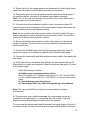
1
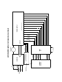
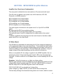
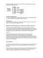
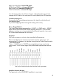
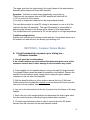
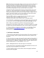
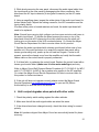
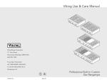
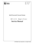
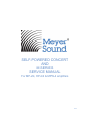
SELF-POWERED CONCERT AND M SERIES SERVICE MANUAL For MP-2/4, HP-2/4 & MPW-4 amplifiers 2012 MEYER SOUND LABORATORIES MSPN: 05.033.040.01 REV B TABLE OF CONTENTS INTRODUCTION Recommended Documentation Pre-Service Checks and Precautions 3 4 4 SECTION I: MP/HP/MPW AMPLIFIER MODULES Flow Chart Amplifier User Panel AC Mains RMS Control Board Power Supply Amplifier Heatsink 5 6 6 7 7 8 9 SECTION II: COMMON FAILURE MODES Circuit breakers trip on power-up or during use A) 2-channel versions B) 4-channel versions C) Unit does not power up D) Unit powers up and immediately shuts off E) Unit powers up, but does not pass signal (unmute) F) Unit powers up, but active LED does not light and no signal passes G) Unit turns on and off in a cyclical fashion H) Unit turns on, but no signal passes or signal is intermittent I) Unit hums or has noise J) Unit's output degrades when paired with other units K) Unit has distorted output 9 11 14 16 16 17 18 19 20 21 22 Introduction From the very beginning, the Meyer Sound Self-Powered Concert and M Series products were designed with the customer in mind. Not only are they easy to set up and use, but they are also easy to service. You will find that the MP-2 & 4, HP-2 & 4 and MPW-4 amplifiers used in the Self-Powered Concert and M Series are completely modular. With the exception of the control boards, most of the modules are interchangeable with any of the Self-Powered Concert or M Series products. The MP and HP amp heatsinks must be kept with their appropriate amplifiers. The HP (high powered) amp heatsinks are double FET modules and cannot be used in the MP amplifiers and vise versa. The MPW-4 amplifier uses one MP amplifier on the top position and one HP amp heatsink in the bottom position. These different heatsinks must be observed when doing any module swapping or replacement. In addition, the transformer for the MP-2/4 and the HP-2 is different from the HP-4 amplifier. The MP/HP amplifiers have been designed with a modular layout to simplify troubleshooting and repairs to the most basic level; just determine which module is at fault and replace that module. This feature allows the user greater flexibility when dealing with problems in the field. In order to perform service on the Self-Powered Concert and M Series, knowledge of the amplifier is required; please read the following section carefully before attempting to service an amplifier. Service procedures for replacing modules are included in the Meyer Sound SelfPowered Series Speaker Service Documentation CD pn: 18.033.083.01. You may also contact the Service Department at Meyer Sound for a link to videos demonstrating module replacement in the HP/MP amplifiers. The following service manual provides detailed information to allow the user to perform a modular assessment of their unit. 3 Recommended Documentation: Meyer Sound Self-Powered Series Speaker Service Documentation Package Available on CD pn: 18.033.083.01 Also, by contacting the Service Department at Meyer Sound you can obtain links to service videos for the MP/HP amplifiers and M’elodie/MJF products. Pre-Service Checks and Precautions: 1. When servicing any electronic assemblies, a clean low static bench should be used and internal assemblies should be kept free of metallic debris. 2. AC power must be disconnected and the Power Supply module allowed to bleed for at least 3 minutes before performing any work inside the chassis. 3. While individual electronic components are very sensitive to static electricity, the completed subassemblies and boards used in the MP/HP/MPW are of relatively low static sensitivity. It is always preferable to use a static control station, but in lieu of this, careful handling will minimize the potential for static damage. When reaching for an assembly (this is when the greatest static potential exists), never grab connector pins or component leads pickup and handle the assembly by its edges or mounting brackets. Always lay assemblies on the same work surfaces as the other electronics which should be a low static or semi-conductive surface. Avoid placing foam or plastic underneath objects as they hold capacitive/static charge. 4. Use caution not to bend any vertical components on the circuit boards as this stress to the components can seriously shorten their life. 5. If there is any dirt, dust, or oil buildup in the chassis, it should be cleaned before reassembling. 4 Audio In earth AC in neutral fuse CONTROL BOARD Audio In Channel B Channel A -15VDC ground +15VDC mute RMS (OPTIONAL) AC MAINS to Drivers AMP HS +15VDC GND -15VDC from here mute starts +108VDC hot see DC harness on pg 8 POWER SUPPLY -108VDC secondary from transformer not used transformer primary +15VDC Transformer CRNT Ground -43VDC GND B GND A +43VDC fuse see DC harness on pg 8 MP/HP/MPW AMPLIFIER BLOCK DIAGRAM Mute Temp Fault -15VDC REF Ground SECTION I - MP/HP/MPW Amplifier Modules Amplifier User Panel (rear of loudspeaker): The user panel is divided into two main sections: AC power and audio input. The AC power is applied to the system via a L6-20 twist-lock, IEC 309, Powercon, or VEAM connector. MP-2 amplifiers use 6 amp breakers MP-4 amplifiers use 8 amp breakers HP-2 amplifiers use 10 amp breakers HP-4 amplifiers use 15 amp breakers MPW-4 amplifiers use 10 amp breakers. The audio signal is introduced to the system via a 3 or 5 pin XLR or VEAM option. MP amps and the SB-2 have polarity switches. The HP amps do not have a polarity switch; pin 2 is positive. The audio pair (pins 2 and 3) is transmitted on a ribbon cable to the control board. In addition, feedback lines returning from the control board on the ribbon cable power the LED's on the User Panel. AC Mains Board: The AC Mains is responsible for determining the AC line voltage and applying it to the appropriate taps on the power transformer. This module also has circuitry for protecting the unit from dangerous power spikes and provides a soft start for lower line loading on the power amp. If the AC Mains has a problem, it may not supply voltage to the power transformer and the unit will not power up. When an acceptable AC line voltage is applied to the HP/MP amplifier, the unit should give at least 2 clicks and the green "active" LED on the front panel will illuminate. If these conditions do not happen there is a fault impeding the AC line voltage. Symptom: Unit will not power up, no lights, no clicks, nothing With the green phoenix connector attached to the AC Mains and with the AC line voltage within normal operating spec (95 -125 VAC; 208-235 VAC) you should hear the relays click on and see the green "active" led illuminate. FOR 120 OR 220 VAC you should hear 3 relay clicks. Lower voltage e.g. Japan 100VAC you will not hear the 2nd relay click. The last relay clicking is the thermistor being taken out of circuit, which is normal. 6 If you do not hear the relays click verify the AC line voltage by measuring the User Panel phoenix connector. Troubleshooting/solution: You can try swapping the AC Mains module with a known good working module to verify the problem in the original "suspect" AC Mains. Connections: With the User Panel removed from the amp chassis, disconnect both the green phoenix connector and the grey sense cable. RMS (Remote Monitoring System) “Communications Board” (Optional): The Remote Monitoring System (RMSª) is an optional real-time monitoring system which connects Meyer Sound self powered speakers with a PC or Mac at the sound mix position or other location. RMS software delivers extensive status and system performance data directly to the operator from every installed speaker. RMS displays include amplifier voltages, limiting activity, power output, temperature, fan and driver status, warning alerts, and other key data. Interconnection of the network computer and speakers is straightforward, using twisted pair cable and simple connectors. The network plugs in to the connectors on the Network Board located at the rear of the computer, and on the User Panel at the rear of each speaker. Control Board: The control board contains the frequency and phase response correction circuitry and the TPL circuitry. The TPL also provides TruPower™ Limiting voice coil protection. The control board module is unique to each product in the Self-Powered Concert Series and M Series amplifiers and these amplifiers can be re-configured by simply changing this module with another TPL control board e.g.: 7 MSL-4 to a 650-P for 2 channel MP amps; MTS-4A to a PSW-6 for 4 channel MP amps; M3D to MILO for 4 channel HP amps and 700HP to 600 HP for 2 channel HP amps You will want to make note of these changes, externally on the amp and also change the LED label on the user panel to correctly identify the LED operation. Troubleshooting note: It is possible that if something went wrong on this board it could stop the unit from passing signal. Try module swapping with a known good working unit to verify. Power Supply Module: The Power Supply board generates the +/-15VDC, +/- 43VDC and +/- 108VDC power rails for the control board and the amplifier electronics. If one of these voltages is missing or is not symmetrical to its differential opposite it can cause DC on the output and cause the unit to fault. Symptom: Unit faults on power up or shuts down immediately after power up Remove the DC harness from the amp heatsink module, apply power and measure the DC voltages on the harness coming from the Power Supply module. - see diagram below * Note: +/- 43VDC and +/- 108VDC are unregulated and may vary from its typical value. This is fine as long as both positive and negative power rails are even. View of the DC harness as seen when connected to the amp heatsink. Amplifier Heatsink Module: The signal path on the HP/MP/MPW amplifiers is very simple. 8 The signal goes from the input board to the control board to the amp heatsink assembly which employs a Class AB/H amplifier. Symptom: Unit faults or shuts down immediately upon power up There are only two reasons that an HP/MP amplifier will shut itself off. 1) DC on one or all of the outputs 2) too high of temperature detected on the amp heatsink module. The most likely module to cause DC voltage to be present on one or all of the outputs is the amp HS assembly. The amp HS assembly is responsible for delivering high currents to the drivers and is subject to high temperatures. This module has built in protection for DC on the outputs or too high temperature. Troubleshooting/solution: Replace with a known good working module and see if the problem clears up in the suspect unit and moves to the known good working unit. SECTION II - Common Failure Modes A. Circuit breakers trip on power up or during use – 2 Channel versions 1. Do not reset the circuit breakers. If the circuit breakers are reset without first determining the cause of the excessive current draw, further damage to the electronics may result. 2. If the amplifier is in the speaker cabinet, remove the eight (8) large diameter Truss head Phillips screws that attach the amplifier to the cabinet. Remove the amplifier from the cabinet slowly, taking care to unplug the green speaker connector on the top side of the amplifier. 3. With the amplifier sitting on a firm surface, remove the four (4) flat head Phillips screws from the amplifier chassis cover and remove the cover over the rear portion of the amplifier, above the fans. 4. Lay unit on its side and remove the six (6) screws from the bottom of the amp chassis. 5. Return the unit to the upright position and disconnect the audio signal cable from the control board by unlocking the gray ribbon cable connector. 6. Lift up the amp heatsink module in order to remove the white DC power harness from the connector on the amp heatsink module. 9 Caution: Be careful not to overflex the circuit board when removing the power harness connector. The connector fits very snug; rock the connector length-wise to work loose. 7. Lift the amp heatsink module out of the chassis and set aside. Do not remove the control board from the amp heatsink assembly at this time. Caution: Never disassemble the amplifier PCB board from the heatsink. The torque on the FET’s is an exact measurement and should not be tampered with. It will void any potential warranty. If the top or the bottom amp heatsink module needs to be replaced refer to Meyer Sound Self Powered Series MP-2 mp heatsink Service Procedure (# 17.033.013.01) for replacement procedures that apply to both the MP-2 and HP2 amplifiers or, contact the Meyer Sound Service Department for links to service videos for this product. 8. With the amp heatsink removed, reset the breakers, and apply AC power to the unit. Check for the following conditions: a) Audible power-up sequence (three clicks). Note: This applies to AC supplies ranging from 110-130 V and 225-250 V. For AC supplies between 90-105 V and 180-215 V, only two clicks will be heard. b) Center fan turns on. c) Power supply LED’s are on (visible through the top of the chassis) Note: The user panel LED will not light as the amp heatsink module is disconnected. 9. If the previous three conditions in step 8 are met, the power supply circuits are functioning properly. It is likely that the amp heatsink module is damaged and will need to be replaced. Refer to Meyer Sound Self Powered Series MP-2 mp heatsink Service Procedure (# 17.033.013.01) for replacement procedures that apply to both the MP-2 and HP-2 amplifiers or, contact the Meyer Sound Service Department for links to service videos for this product. If any of the previous three conditions in step 8 are not met the AC mains board or the power supply could be damaged, continue to step 10. 10. To assess the power supply system, unplug the AC to the unit and allow the supplies to bleed (about 3 minutes). Remove the eight (8) small head screws from the user panel and remove the user panel. 10 Remove the audio signal cable from the audio input board by disengaging the locking connector. Also remove the AC harness from the AC mains board (4 wire green connector). 11. Remove the sense cable (gray ribbon cable) and the transformer primary connector (7 wire green connector) from the AC mains board. 12. While firmly holding the AC mains board, remove the three (3) screws on the top of the chassis and remove the entire AC Mains module. 13. Replace the AC Mains module with a known good module (either new or from another unit). Make sure to reconnect the sense cable and the transformer primary connector. Replace the user panel and repeat the power up sequence as stated in step 8. 14. If the three conditions stated in step 8 are met this time, the power supply circuits are functioning properly. It is most likely that the AC Mains Board is damaged and will need to be replaced. You can refer to Meyer Sound Self Powered Series MP-2/4 AC Mains Service Procedure (#17.033.022.01) for replacement procedures for the AC Mains board or contact the Meyer Sound Service Department for links to service videos for this product. 15. If the unit still does not power up properly, it is likely that the power supply module is damaged. You can refer to Meyer Sound Self Powered Series MP-2/4 Power Supply Service Procedure (#17.033.076.01) for replacement procedures for the Power Supply board or contact the Meyer Sound Service Department for links to service videos for this product. B. Circuit breakers trip on power up or during use – 4 Channel versions 1. Do not reset the circuit breakers. If the circuit breakers are reset without first determining the cause of the excessive current, further damage to the electronics may result. Caution: If the breakers pop out and are pushed back in and power is reapplied, without first verifying the fault in the amp, the thermistor (black circular component glued to relay 1) on the AC Mains board could be damaged. Visually inspect the thermistor for damage and replace the AC Mains as needed.” 11 You can contact the Service Department for links to service videos on this product. 2. If the amplifier is in the speaker cabinet, remove the eight (8) large head screws that attach the amplifier to the cabinet. Remove the amplifier from the cabinet slowly, taking care to unplug both green speaker connectors on the top side of the amplifier. 3. With the amplifier sitting on a firm surface, remove the four (4) screws from the amp chassis cover and remove the cover. 4. Disconnect the audio signal cable from the top control board by unlocking the ribbon cable. 5. Remove the six (6) screws from the top amp heatsink module bracket (3 per side). Lift up the amp heatsink module in order to remove the brown DC power harness from the connector on the top amp heatsink module. Caution: Be careful not to over-flex the circuit board when removing the power harness connector. The connector fits very snug; rock the connector length-wise to work loose. 6. Lift the top amp heatsink module out of the chassis and set aside. Do not remove the control board from the amp heatsink module at this time. From the “front” (user panel) side of the amplifier: 7. Remove the eight (8) small head screws from the user panel. 8. While slowly removing the user panel, disconnect the audio signal cable from the input board on the user panel by disengaging the locking connector. Also disconnect the AC input connector (4 wire green connector) from the AC mains board. 9. Remove the sense cable (gray ribbon cable) and the transformer primary connector (7 wire green connector) from the AC mains board. 10. While firmly holding the AC mains board, remove the three (3) screws on the top of the chassis and remove the board. 11. Disconnect the white DC power harness from the power supply module. Caution: Be careful not to over-flex the circuit board when removing the power harness connector. The connector fits very snug; rock the connector length-wise to work loose. 12. Lay the unit on either side and remove the six (6) screws from the bottom of the amp chassis. 12 13. Return the unit to the upright position and disconnect the audio signal ribbon cable from the bottom control board by unlocking the connector. 14. Remove the green four (4) pin male connector mounted on the top edge of the amplifier chassis; this leads to the bottom amp heatsink assembly. Note: Two (2) nuts with lock washers secure the two (2) screws. Make sure to remove these nuts from the chassis. 15. Lift up the bottom amp heatsink module in order to remove the white DC power harness from the connector on the amp heatsink module. Disconnect the power harness from the amp heatsink module. Note: As you are lifting the amp heatsink module, thread the white DC power harness through the chassis towards the amp heatsink module. This will allow you to lift the module clear of the amp chassis. 16. Remove the bottom amp heatsink module, taking care to not disturb the position of the fans. Do not remove the control board from the amp heatsink module at this time. 17. Position the AC Mains board inside the chassis and replace the three (3) screws into the top of the chassis to reattach the AC Mains board bracket. 18. Connect the sense cable and the transformer primary cable. Also replace the user panel. 19. At this point the top and bottom amp heatsink are disconnected but the AC Mains board is in place and connected. Reset the breakers, and apply AC power to the power supply. Verify the following conditions: a) Audible power-up sequence (three clicks). Note: This applies to AC supplies ranging from 110-130 V and 225-250 V. For AC supplies between 90-105 V and 180-215 V, only two clicks will be heard. b) Top and bottom center fans turn on. c) Power supply LED’s on (visible through the top of the chassis) Note: The user panel LED will not light as the amp heatsink module is disconnected. 20. If the previous three conditions are met, the power supply circuits are probably functioning properly. It is most likely that one or both of the amp heatsink modules are damaged and will need to be replaced. You can install the bottom amp heatsink assembly and apply power to the unit if the three previous conditions are meet the top amp heatsink module is the likely 13 culprit. If the three previous conditions are not met, the bottom amp heatsink likely needs to be replaced. Caution: Never disassemble the amplifier PCB board from the heatsink. The torque on the FET’s is an exact measurement and should not be tampered with. If the top or the bottom amp heatsink module needs to be replaced, please refer to Meyer Sound Self Powered Series MP-4 Amp Heatsink Service Procedure (#17.033.013.02) for replacement procedures or contact the Meyer Sound Service Department for links to service videos for this product or further assistance. 21. To assess the power supply system, unplug the unit and allow the supplies to bleed (about 3 minutes). Remove the eight (8) small head screws from the user panel and remove the panel. Remove the audio signal cable from the audio input board by disengaging the locking ribbon connector. Also remove the AC input cable from the AC Mains board (4 wire green connector). 22. Remove the sense cable (gray ribbon cable) and the transformer primary connector (7 wire green connector) from the AC mains board. 23. While firmly holding the AC mains board, remove the three (3) screws on the top of the chassis and remove the entire board. 24. Replace the AC Mains board with a known good board (either new or from another unit). Make sure to reconnect the sense cable and the transformer primary connector. Replace the user panel and repeat the power up sequence as stated in step 19. You can refer to Meyer Sound Self Powered Series MP-2/4 AC Mains Service Procedure (#17.033.022.01) for replacement procedures for the AC Mains Board or contact the Meyer Sound Service Department for links to service videos for this product or further assistance. 26. If the unit still does not power up properly, it is likely that the power supply module is damaged. You can refer to Meyer Sound Self Powered Series MP-2/4 Power Supply Service Procedure (#17.033.076.01) for replacement procedures for the Power Supply board or contact the Meyer Sound Service Department for links to service videos for this product or further assistance. C. Unit does not power up: 1. Using a voltmeter, check the AC voltage supply to the amplifier. Make sure that the voltage is within the specified operating range as listed on the user panel. 14 Note: If the AC voltage exceeds 270 VAC, the AC mains board may be damaged. 2. Verify that the breakers are not tripped. If the breakers are tripped, do not reset. See section A for details. 3. If the amplifier is in the speaker cabinet, remove the eight (8) large head screws that attach the amplifier to the cabinet. Remove the amplifier from the cabinet slowly, taking care to unplug the green speaker connector(s) on the top side of the amplifier. 4. With the amplifier sitting on a firm surface, remove the eight (8) small head screws from the user panel. 5. While slowly removing the user panel, disconnect the audio signal cable from the audio input board on the user panel by disengaging the locking connector. Check the AC input connector (4 wire green connector) on the AC mains board before disconnecting it. Is it tight? If not, seat tightly and reconnect the user panel following the steps in reverse and try re-applying power to see if the amp powers up normally. 6. Once the user panel is removed, check the following AC connections: a). Transformer primary connector (green 7 pin on AC Mains board) b). Transformer secondary connector (green 8 pin on power supply board) c). AC connections on user panel – 3 spots (the breakers, the filter, the AC inlet). 7. Reconnect the user panel and apply power. Check to see if the following conditions are met: a) Audible power-up sequence (three clicks). Note: This applies to AC supplies ranging from 110-130 V and 225-250 V. For AC supplies between 90-105 V and 180-215 V, only two clicks will be heard. b) Center fan(s) turns on. c) Power supply LED’s turn ON (visible through the top of the chassis; red leds). If the unit still does not power up, unplug the unit and continue to step 8. 8. Remove the user panel and check the AC Mains board for damaged components or a burned electronics smell. Usual mode of failure is a damaged thermistor (the round disc next to Relay 1). If the AC Mains board is damaged, it will have to be replaced. 9. If the AC Mains board appears undamaged, remove the board. To do this, 15 remove the sense cable (gray ribbon cable) and the transformer primary connector (7 wire green connector) from the AC Mains board. 10. While firmly holding the AC Mains board, remove the three (3) screws on the top of the chassis and remove the board. 11. If the unit was subjected to overvoltage conditions (> 270 VAC), the AC Mains board fuse could be damaged. Locate the fuse (F1) on the AC Mains board (between Relay 1 and the AC input connector) and check the continuity with an ohmmeter. If the fuse is open, the AC Mains board will have to be replaced. Refer to Meyer Sound Self Powered Series MP-2/4 AC Mains Service Procedure (# 17.033.022.01). for replacement procedures for the AC mains module or contact the Meyer Sound Service Department for links to service videos for this product or further assistance. 12. If the AC Mains appears to be fine, try replacing the board with a known good working module (either a new one or from another unit). Install the good board and repeat the power up sequence described in step 7. 13. If the unit still does not power up properly, it is likely that the transformer or the power supply module is damaged. You can refer to Meyer Sound Self Powered Series MP-2/4 Power Supply Service Procedure (#17.033.076.01) for replacement procedures for the Power Supply board or contact the Meyer Sound Service Department for links to service videos for this product or further assistance. D. Unit powers up and immediately shuts off: This condition is typically an indication of partial MOSFET failure. Generally, when one side of a two channel amplifier has shorted MOSFETs, a large DC offset is created on that side from the voltage supply rails. The amplifier sensing circuits detect this condition on power up and send a fault signal, and the amplifier shuts off. Please refer to Section A for troubleshooting information. Note 1: If the unit is excessively hot (i.e. the heatsink > 80 °C), it will shut off. Let the unit cool sufficiently and try again. E. Unit powers up but does NOT pass signal: 1. If the amplifier is in the speaker cabinet, remove the eight (8) large head screws that attach the amplifier to the cabinet. As you slowly remove the 16 amplifier from the cabinet, look at the green speaker connector(s) on the top of the amp chassis. Make sure that the connector(s) is fully seated. If it is not fully seated, seat the connector and push the amplifier back in the cabinet. Apply power and signal. If the unit still does not pass signal, unplug the unit and remove it from the cabinet. 2. With the amplifier sitting on a firm surface, remove the eight (8) small head screws from the user panel. 3. While slowly removing the user panel, verify the connection ribbon cable connection to the input board is firmly seated. If so, disconnect the audio signal cable from the input board on the user panel by disengaging the ribbon connector. Disconnect the AC input connector (4 wire green connector) on the AC Mains board. 4. Check the sense cable connection to the AC Mains board. Make sure that it is connected properly. 5. If the unit still does not un-mute, the muting relay circuit on the control board or the muting control circuit on the Power Supply module could be damaged. 6. Visually inspect the ribbon cable connection to the control board to make sure it is firmly seated. 7. Try replacing the control board with a known good board (make sure that it is the same type) to see if the problem clears up. Refer to Meyer Sound Self Powered Series TruPower Limiting Upgrade Procedure (#17.033.042.01 for MP/HP-2 and # 17.033.042.02 for MP/HP-4 ) or contact the Meyer Sound Service Department for links to service videos for this product or further assistance. If the unit still does not un-mute, the power supply module is possibly damaged. You can try module swapping with a known good working power supply from another HP/MP amplifier. You can refer to Meyer Sound Self Powered Series MP-2/4 Power Supply Service Procedure (#17.033.076.01) for replacement procedures for the Power Supply board or contact the Meyer Sound Service Department for links to service videos for this product or further assistance. F. Unit powers up but Active LED does not light and no signal passes: 1. If the amplifier is in the speaker cabinet, remove the eight (8) large head screws that attach the amplifier to the cabinet. Remove the amplifier from the 17 cabinet slowly, taking care to unplug the green speaker connector(s) on the top side of the amplifier. 2. With the amplifier sitting on a firm surface, remove the eight (8) small head screws from the user panel. 3. While slowly removing the user panel, disconnect the AC input connector (4 wire green connector) on the AC mains board. Check the audio ribbon cable connection on the audio input board. If the connection is loose, reconnect the audio ribbon cable firmly. Reconnect the AC input connector, reattach the user panel to the unit, and repeat the power up sequence. If the Active LED still does not light proceed to step 4. 4. Remove the amplifier chassis cover and verify that the audio ribbon cable connection on the control board is connected properly. 5. Replace the user panel and retry. If the unit still does not pass signal, the control board could be damaged. 6. Replace the control board with a known good control board (make sure it is the same type) and retry. Refer to Meyer Sound Self Powered Series TruPower Limiting Upgrade Procedure (# 17.033.042.01 for MP/HP-2 and # 17.033.042.01 for MP/HP-4) or contact the Meyer Sound Service Department for links to service videos for this product or further assistance. Note: If the unit comes on and the audio signal passes, but the LED does not light, the audio input board probably has a bad LED and the input module needs to be replaced. 7. If the unit still does not operate correctly, please contact the Meyer Sound Service Department [email protected] to open an RA (Return Authorization) to send the unit in for service. G. Unit turns on and off in a cyclical fashion: 1. Check the AC line for fluctuation or sag under load. This can be best achieved by using a "Y" connector on your power cable. Connect one side of the "Y" to the amplifier and the other side of the "Y" to a voltmeter. Monitor the voltage as the unit turns on and during use. 2. If the line voltage is stable, try replacing the AC Mains board with a known good one. Refer to Meyer Sound Self Powered Series MP-2/4 AC Mains Service Procedure 18 (# 17.033.022.01) or contact the Meyer Sound Service Department for links to service videos for this product or further assistance. 3. If the unit still cycles on/off please contact the Meyer Sound Service Department [email protected] to open an RA (Return Authorization) to send the unit in for service. H. Unit turns on, but no signal passes or signal intermittent: 1. With the unit on, check the audio signal source for adequate input level. Also check that signal passes with a known good unit. 2. If the signal level is adequate, check the signal cable for intermittent connections. This can be accomplished by moving the signal cable back and forth at each end and at various places within the cable length. Flip the input polarity switch two times and listen for any change in level. 3. Check to see if the XLR jack is firmly locked in place and that it does not move inward when engaged. 4. Turn the unit off and slowly remove the amplifier from the cabinet so that the output harness is visible. Verify that the output driver harness is firmly seated within the mating connector. Also check for loose wires within the output harness connector. 5. Verify that the output driver harness is firmly connected to the drivers. This can be done by removing the driver from the cabinet or by using an ohmmeter to measure the resistance of the drivers. Note: Some high drivers will have a capacitor in series making resistance measurements inaccurate. Check continuity at the driver terminals and not the connector end of the harness. High drivers can best be reached by removing the closest handle cup on the cabinet. 6. With the amplifier sitting on a firm surface, remove the eight (8) small head screws from the user panel. 7. While slowly removing the user panel, disconnect the audio signal cable from the input board on the user panel by disengaging locking the connector. Also disconnect the AC input connector (4 wire green connector) on the AC Mains board. 8. Using a magnifying glass, inspect the solder joints of the audio input board for broken solder joints. Inspect the locking connector and the XLR connectors. If broken solder joints or burned resistors are found, the audio input board will need to be replaced. 19 Note: Ground loops carrying high voltages can burn some resistors and traces in the audio input board. To replace the board remove the screw on top of the board and unlock the XLR connectors from their shells turning the small self locking pins on the center of the XLR counterclockwise. Or contact the Meyer Sound Service Department for links to service videos for this product. 9. Replace the audio input board with a known good board (either new or from another unit. One quick technique is to swap the complete user panel with a known good working unit), power up the unit and test it again. If signal is still not present, remove the chassis cover from the amplifier and verify that the audio ribbon cable on the control board is properly connected. Check the RMS module for corrosion that could short the audio to ground. Unplug the ribbon cable to the RMS module and retry. Check the sense cable to the AC Mains to see if it is properly seated. 10. If all else fails, try replacing the control board. Replace the control board with a known good control board (make sure it is the same model type) and retry. Refer to Meyer Sound Self Powered Series TruPowerLimiting Upgrade Procedure (# 17.033.042.01 for MP-2 and # 17.033.042.01 for MP-4). Or contact the Meyer Sound Service Department for links to service videos for this product 11. If the unit still does not operate correctly please contact the Meyer Sound Service Department [email protected] to open an RA (Return Authorization) to send the unit in for service. I. Unit hums or has noise: 1. Disconnect the audio signal from the source and see if the noise goes away. If the noise goes away, there is a problem with the audio source; external to the enclosure. 2. If the noise does not go away, disconnect the audio cable from the amplifier, if the noise goes away check the wiring of the signal cable. The audio signal cable should be wired in a "balanced" configuration; that is, the audio signal should be present between pins 2 & 3, never between 1 & 2 or 1 & 3. NOTE: VEAM panels will hum if the audio input is not terminated. 3. If the unit has hum or noise without a signal cable connected, turn the unit off and slowly remove the amplifier from the cabinet. 4. With the amplifier sitting on a firm surface, remove the eight (8) small head screws from the user panel. 20 5. While slowly removing the user panel, disconnect the audio signal cable from the input board on the user panel by disengaging the ribbon connector. Also disconnect the AC input connector (4 wire green connector) on the AC mains board. 6. Using a magnifying glass, inspect the solder joints of the audio input board for broken solder joints. Inspect the locking connector, the XLR connectors and the Input polarity switch. If broken solder joints or burned resistors are found, the audio input board will need to be replaced. Note: Ground loops carrying high voltages can burn some resistors and traces in the audio input board. To replace the board remove the screw on top of the board and unlock the XLR connectors from their shells turning the small self locking pins on the center of the XLR counterclockwise. Or contact the Meyer Sound Service Department for links to service videos for this product. 7. Replace the audio input board with a known good board (either new or from another unit. One quick technique is to swap the complete user panel with a known good working unit), power up the unit and test it again. If noise is still present, remove the chassis cover from the amplifier and verify that the audio ribbon cable on the control board is properly connected. 8. If all else fails, try replacing the control board. Replace the control board with a known good control board (make sure it is the same model/type) and retry. Refer to Meyer Sound Self Powered Series Procedure (# 17.033.042.01 for MP-2 and # 17.033.042.01 for MP-4) the procedure also applies to the HP amplifiers. Or contact the Meyer Sound Service Department for links to service videos for this product or further assistance. 9. If the unit still does not operate correctly please contact the Meyer Sound Service Department [email protected] to open an RA (Return Authorization) to send the unit in for service. J. Unit’s output degrades when paired with other units: 1. Check the polarity switch setting against the other cabinets. 2. Make sure that all the audio signal cables are wired the same. 3. If the drivers have been changed recently, check the driver wiring for correct polarity. Note: All speakers shipped from Meyer Sound are acoustically tested for phase accuracy. 21 4. Check to see that the units in question are either all TPL or all non-TPL. Using TPL and non-TPL together may produce audible differences at the different limiting thresholds. K. Unit has distorted output: 1. Try running the same signal (individually, not looped) into two similar units. If both units are distorted, check the signal source level for overload. 2. If only one unit has distorted output, swap the entire amplifier with a known good working unit and see if the problem clears up in the suspect enclosure and it the problem of distortion moves to the known good working enclosure. This will determine if the problem is electronic or driver related. If electronic: 3. Replace the control board with a known good control board (make sure it is the same model/type) and retry. Refer to Meyer Sound Self Powered Series Procedure (# 17.033.042.01 for MP-2 and # 17.033.042.01 for MP-4) the procedure also applies to the HP amplifiers. Or contact the Meyer Sound Service Department for links to service videos for this product or further assistance. 4. If the unit still does not operate correctly please contact the Meyer Sound Service Department [email protected] to open an RA (Return Authorization) to send the unit in for service. Meyer Sound Laboratories, Inc. 2832 San Pablo Ave. Berkeley, CA 94702 510-486-1166 MSPN: 05.033.040.01 REV B 22