1
835959-UIM-A-0112
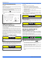
CFM SELECTION BOARD SETTINGS
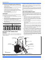
For proper system operation the CFM Selection Board jumpers must be
set properly.
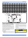
Refer to the Tabular Data Sheet for the recommended air flow settings
for each size condensing unit.
Set the cooling speed per the instructions for the air handler or furnace
by selecting the correct COOL and ADJ taps. Verify the airflow using
the LED display on the CFM selection board.
The HEAT PUMP jumper MUST be removed for proper system operation.
The HUMIDISTAT jumper must also be removed if a dehumidistat is
installed.
The TOTAL SYSTEM CHARGE must be permanently stamped on the
unit data plate.
Total system charge is determined as follows:
1.
2.
3.
Determine outdoor unit charge from tabular data sheet.
Determine indoor coil adjustment from tabular data sheet.
Calculate the line charge using the tabular data sheet if line length
is greater than 15 feet.
4. Total system charge = item 1 + item 2 + item 3.
5. Permanently stamp the unit data plate with the total amount of
refrigerant in the system.
Use the following subcooling charging method whenever additional
refrigerant is required for the system charge. A superheat charging
method is not suitable for TXV equipped systems.
CFM SELECTION BOARD
TAP SELECTION
D
C
B
A
D
C
B
A
COOL
HEAT
ADJ
DELAY
REMOVE FOR
HEAT PUMP
HUMIDISTAT
Refrigerant charging should only be carried out by a qualified air
conditioning contractor.
Measurement Method
If a calibrated charging cylinder or accurate weighing device is available, add refrigerant accordingly.
FIGURE 8: CFM Selection Board
Compressor damage will occur if system is improperly charged. On
new system installations, charge system per tabular data sheet for
the matched coil and follow guidelines in this instruction.
SECTION VI: EVACUATION
It will be necessary to evacuate the system to 500 microns or less. If a
leak is suspected, leak test with dry nitrogen to locate the leak. Repair
the leak and test again.
To verify that the system has no leaks, simply close the valve to the vacuum pump suction to isolate the pump and hold the system under vacuum. Watch the micron gauge for a few minutes. If the micron gauge
indicates a steady and continuous rise, it’s an indication of a leak. If the
gauge shows a rise, then levels off after a few minutes and remains
fairly constant, its an indication that the system is leak free but still contains moisture and may require further evacuation if the reading is
above 500 microns.
SECTION VII: SYSTEM CHARGE
R-410A refrigerant cylinders are rose colored, and have a dip tube
which allows liquid to flow out of the cylinder in the Upright Position. Always charge the system slowly with the tank in the upright
position.
The factory charge in the outdoor unit includes enough charge for the
unit and the highest sales volume evaporator. Some indoor coil
matches may require additional charge. See tabular data sheet provided in unit literature packet for charge requirements.
Do not leave the system open to the atmosphere. Unit damage
could occur due to moisture being absorbed by the POE oil in the
system. This type of oil is highly susceptible to moisture absorption.
8
Check flare caps on service ports to be sure they are leak tight. DO
NOT OVERTIGHTEN (between 40 and 60 inch - lbs. maximum).
SECTION VIII: SYSTEM START-UP
ENERGIZE CRANKCASE HEATER
If this unit is equipped with a crankcase heater for the compressor, a
warning label with an adhesive back is supplied in the unit installation
instruction packet. This label should be attached to the field supplied
disconnect switch where it will be easily seen.
In order to energize the crankcase heater, set the indoor cooling thermostat to the OFF position. Close the line power disconnect to the unit.
An attempt to start the compressor without at least 8 hours of
crankcase heat will damage the compressor.
WITH POWER TO UNIT AND THERMOSTAT IN COOLING POSITION:
1.
In the cooling cycle, discharge gas is pumped to the outdoor coil
which is the condenser. The indoor coil is the evaporator.
2.
If fan switch is in ON position, a circuit is made through blower
relay to provide continuous blower operation.
3.
With fan switch in AUTO position, a circuit is made from thermostat cooling contact through blower relay to provide blower operation.
4.
System will cycle with thermostat demand to provide cooling as
needed.
Johnson Controls Unitary Products