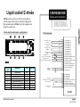
1
FLYDAT OPERATOR'S MANUAL
®
ROTAX-BOMBARDIER
Flydat operator's manual
Non TSO approved
Content
Section 1
Introduction.............................................................
Section 2
Description..............................................................
Section 3
Description of design..............................................
Section 4
Possible configuration.............................................
Liquid cooled 2-stroke............................................
Air cooled 2-stroke.................................................
Liquid cooled 4-stroke............................................
Section 5
Possible connection.................................................
Section 6
Technical data..........................................................
Section 7
Warning and Alarm 447, 503, 582UL.....................
Warning and Alarm 618UL and 912UL..................
Warning and Alarm 912S and 914UL.....................
Section 8
Installation...............................................................
Section 9
Sensors kits..............................................................
Section 10
Installation of the sensors.......................................
Pictures of the sensors............................................
Installation of the sensors on 2-stroke engine........
Installation of the sensors on 4-stroke engine........
Installation of the sensors.......................................
Flydat Operator's manual
CONTENT OF
page ii
page 1
Operator's manual
®
page 2
page 3
page 4
page 5
page 6
page 7
page 8
page 9
page 10
page 11
page 12
page 13
page 14
page 15
page 16
page 17
page 18
Section 11
Initial start-up.........................................................
Section 12
Delete Service message..........................................
Section 13
Possible display.......................................................
Section 14
Flydat status............................................................
Section 15
Data recording in operation....................................
Section 16
Data downloading...................................................
Section 17
Firmware update.....................................................
Section 18
iFamily® bus..........................................................
Section 19
Message and reports of errors.................................
page 19
page 20
page 21
page 22
page 23
page 24
page 25
page 26
page 27
page 28
page 29
page i
Rev. A, 03/04
Dear Customer
Section
1 Congratulations to your decision to use the FLYdat,
specially developed for ROTAX Aircraft Engines for indicating
and storing engine operation data. Prior to taking the
FLYdat into service, please, read the Operator's Manual carefully,
as it will acquaint you with the basic knowledge of technical
data, installation and the safe handling of the FLYdat.
If you do not understand anything in this manual or in case
of any question arising, please, contact the nearest authorized
ROTAX Distributor or Service Partner.
INTRODUCTION
Thanks
®
BOMBARDIER-ROTAX G.m.b.H & Co.Kg
Aircraft engines division
A-4623, Gunskirchen, Austria
Web side address: http://www.rotax-aircraft-engines.com
Except as expressly provided below, no part of this manual
may be downloaded, transmitted, copied, reproduced,
disseminated or stored in any storage medium, for any purpose
without the express prior written consent of the
Rotax-Bombardier company. Address your questions about the
technical information to Rotax-Bombardier. Other information
about sale, distribution should be directed to our exclusive
distributors (see World Distributor list on our web pages).
All the information in this User‘s manual is subject to change
without a prior notice.
© Copyright 2004, TL elektronic / Rotax-Bombardier. All rights reserved.
Flydat Operator's manual
page ii
Rev. A, 03/04
Description
INTRODUCTION
Description
Section
2 The FLYdat has not undergone any safety and durability
®
examination to the Standards of Civil Aviation, but it does
incorporate the latest technical development and has been
thoroughly tested.
Despite the FLYdat being a precise instrument, false
indication or misinterpreting of data could occur.
By utilizing the FLYdat, the user acknowledges
a possible danger and responsibility for all risk.
To minimize the risk, study the Operator's Manual carefully.
Before the content of the Manual is not understood completely,
you may not take the FLYdat into service.
Please, pay attention to the following symbols throughout
the manual, emphasizing particular information.
Identifies an instruction, that, if not
followed, may cause serious injury
or even death.
ATTENTION: Identifies an instruction that, if not followed,
may severely damage the engine or other
components.
NOTE:
Information useful for better handling of the
FLYdat
WARNING:
P.T.O. stands for power take off side and M.S. for magneto
side throughout the Technical Documentation of Rotax, for
precise destination of location
Flydat Operator's manual
page 1
Rev. A, 03/04
Description of design
Section
3 The FLYdat represents an instrument specially developed
for ROTAX Aircraft engines for the indication and acquisition
of engine operating data readily accessible for the pilot.
INTRODUCTION
Description
®
The FLYdat is furnished with 8 sensor input ports,
which can be occupied variably according to the engine type.
The operating data is being permanently compared with the
specific engine operating limit. If the signalled operating data
exceeds the stored operating limit, the FLYdat will warn
the pilot.
The FLYdat keeps the pilot informed on the following
actual readings:
• Engine speed
• Cylinder head temperature
• Ambient air temperature (not on engines 912/914)
• Temperature of cooling water (only on engines 582UL, 618UL)
• Oil temperature and oil pressure (only on engines 912/914)
The separately picked up readings are issued in accordance
to display allocation.
For maintenance and analyses of engine shortcomings, the
FLYdat picks up and stores the essential operating data.
For the safety's sake, the programmed service date reminds
you of the scheduled maintenance of the engine.
The handy unit offers a number of appreciable assets compared
to the conventional dial gauge indication. Besides the easy
installation, the low weight and compact size are the essential
advantages of the FLYdat.
Besides the topical data, the FLYdat shows also the hours
of operation.
Flydat Operator's manual
page 2
Rev. A, 03/04
Possible configuration
INTRODUCTION
Configuration
Section
4 The FLYdat is supplied by Rotax with an undefined
®
configuration.
With the standard configuration, all trigger levels for warning
and alarm system are set to the maximum of the measuring
range, i.e. no checks for exceeding the warning limits.
The FLYdat can be coordinated by the authorized
Rotax Distributor with the respective engine type.
With this configuration, Warning and Alarm limits are set
for the specific channels.
• Undefined
• 447 UL SCDI
• 503 UL DCDI
• 582 UL DCDI
• 618 UL DCDI
• 912 DCDI series
• 912S DCDI series
• 914 DCDI series
Flydat Operator's manual
By the configuration of the FLYdat, the engine type, engine
number, hours of operation, temperature unit and the respective
engine limits are programmed.
NOTE:
If the FLYdat is utilized on a used engine,
it is possible to set the time of operation
WARNING:
If using the FLYdat with the undefined
configuration, the indication will work
flawless, but as Warning and Alarm limits
are set to a high level, there is no warning
in case of danger.
page 3
Rev. A, 03/04
Liquid cooled 2-stroke
FLYdat is always delivered with the front plate for
4-stroke engines but without a defined configuration.
By programming the FLYdat, it will be adapted to the
respective engine type.
3
5
RPM
RPM
1/min
EGT/PTO
EGT/PTO
°C
CHT/PTO
CHT/PTO
°C
Wiring diagram:
7
COOLANT
COOLANT
°C
Thermocouple 1 Type K
EGT P.T.O.
DATA
®
x 0,1h
HOURS
HOURS
°C
EGT/MAG
EGT/MAG
Display and connection
®
2-stroke liquid cooled engine configuration:
1
CONFIGURATION
°C
CHT/MAG
CHT/MAG
Thermocouple 2 Type K
CHT P.T.O.
Thermocouple 3 Type K
EGT M.S.
°C
AIRAIR
Thermocouple 4 Type K
CHT M.S.
®
SchecK
4
2
6
8
Termperature sensor 1
Type PT 100 - Coolant temperature
Temperature sensor 2
Type PT 100 - Ambient air temperature
00998
Display
field
1
2
3
4
5
6
7
8
Designation
Unit
Resolution
Engine speed
Hours of operation
Exhaust gas temp. PTO
Exhaust gas temp. MS
Cylinder head temp. PTO
Cylinder head temp. MS
Coolant temperature
Ambient air temperature
rpm
h
°C or °F
°C or °F
°C or °F
°C or °F
°C or °F
°C or °F
1
0,1
1 or 10
1 or 10
1
1
1
1
ALARM UNIT
(horn, lamp ...)
max 1Amp
Aircraft ground
Aircraft power 10.0 to 32 Volts
Memory / Info button
Revolution counter
signal
white
green
white
green
white
green
white
green
1 - Thermocouple 1 (-)
2 - Thermocouple 1 (+)
3 - Thermocouple 2 (-)
4 - Thermocouple 2 (+)
5 - Thermocouple 3 (-)
6 - Thermocouple 3 (+)
7 - Thermocouple 4 (-)
8 - Thermocouple 4 (+)
9 - Temperature sensor 1
10 - Ground for temperature sensor 1
11 - Temperature sensor 2
12 - Ground for temperature sensor 2
13 - Oil pressure sensor
14 - Ground for oil pressure sensor
15 - Power for oil pressure sensor
16 - Ground for ALARM unit
17 - ALARM output
18 - iFamily® (ISDA)
19 - iFamily® (ISCL)
20 - Aircraft ground
21 - Aircraft power 10.0 to 32.0 Volts
22 - Memory / Info button
23 - Ground for Pick-Up sensor
24 - Pick-Up sensor (4-stroke engines)
25 - Pick-Up sensor (2-stroke engines)
FLYDAT
Flydat Operator's manual
page 4
Rev. A, 03/04
Air cooled 2-stroke
CONFIGURATION
Display and connection
FLYdat is always delivered with the front plate for
4-stroke engines but without a defined configuration.
By programming the FLYdat, it will be adapted to the
respective engine type.
®
2-stroke air cooled engine configuration:
3
1
RPM
EGT/PTO
5
Wiring diagram:
7
CHT/PTO
Thermocouple 1 Type K
EGT P.T.O.
DATA
®
EGT/MAG
HOURS
CHT/MAG
Thermocouple 2 Type K
CHT P.T.O.
Thermocouple 3 Type K
EGT M.S.
Thermocouple 4 Type K
CHT M.S.
AIR
®
SchecK
4
2
6
8
Temperature sensor 2
Type PT 100 - Ambient air temperature
00999
Display
field
1
2
3
4
5
6
7
8
Designation
Unit
Resolution
Engine speed
Hours of operation
Exhaust gas temp. PTO
Exhaust gas temp. MS
Cylinder head temp. PTO
Cylinder head temp. MS
empty
Ambient air temperature
rpm
h
°C or °F
°C or °F
°C or °F
°C or °F
1
0,1
1 or 10
1 or 10
1
1
°C or °F
1
ALARM UNIT
(horn, lamp ...)
max 1Amp
Aircraft ground
Aircraft power 10.0 to 32 Volts
Memory / Info button
Revolution counter
signal
white
green
white
green
white
green
white
green
1 - Thermocouple 1 (-)
2 - Thermocouple 1 (+)
3 - Thermocouple 2 (-)
4 - Thermocouple 2 (+)
5 - Thermocouple 3 (-)
6 - Thermocouple 3 (+)
7 - Thermocouple 4 (-)
8 - Thermocouple 4 (+)
9 - Temperature sensor 1
10 - Ground for temperature sensor 1
11 - Temperature sensor 2
12 - Ground for temperature sensor 2
13 - Oil pressure sensor
14 - Ground for oil pressure sensor
15 - Power for oil pressure sensor
16 - Ground for ALARM unit
17 - ALARM output
18 - iFamily® (ISDA)
19 - iFamily® (ISCL)
20 - Aircraft ground
21 - Aircraft power 10.0 to 32.0 Volts
22 - Memory / Info button
23 - Ground for Pick-Up sensor
24 - Pick-Up sensor (4-stroke engines)
25 - Pick-Up sensor (2-stroke engines)
FLYDAT
Flydat Operator's manual
page 5
Rev. A, 03/04
Liquid cooled 4-stroke
FLYdat is always delivered with the front plate for
4-stroke engines but without a defined configuration.
By programming the FLYdat, it will be adapted to the
respective engine type.
3
RPM
5
EGT/PTO
CHT
Wiring diagram:
7
OIL TEMP
Thermocouple 1 Type K
EGT P.T.O. - right
DATA
®
EGT/MAG
HOURS
LEFT-RIGHT
Display and connection
®
4-stroke liquid cooled engine configuration:
1
CONFIGURATION
Thermocouple 2 Type K
EGT P.T.O. - left
Thermocouple 3 Type K
EGT M.S. - right
Thermocouple 4 Type K
EGT M.S. - left
OIL PRESS
®
SchecK
4
2
Display
field
1
2
3
4
5
6
7
8
6
Designation
8
Unit
Resolution
Termperature sensor 1
Type PT 100 - Oil temperature
Temperature sensor 2
Type PT 100 - CHT
Oil pressure sensor
(pasive resistive)
Engine speed
Hours of operation
Exhaust gas temp. AS
Exhaust gas temp. MS
Cylinder head temp
<- - - >
Oil temeperature
Oil pressure
NOTE: Arrow
Arrow
rpm
h
°C or °F
°C or °F
°C or °F
1
0,1
1 or 10
1 or 10
1
°C or °F
bar or PSI
1
0,1
denotes left line of cylinder
denotes right line of cylinder
The change over of the readings of exhaust
gas temperature is every 5 seconds.
Flydat Operator's manual
ALARM UNIT
(horn, lamp ...)
max 1Amp
Aircraft ground
Aircraft power 10.0 to 32 Volts
Memory / Info button
Revolution counter
Pick-Up
white
green
white
green
white
green
white
green
1 - Thermocouple 1 (-)
2 - Thermocouple 1 (+)
3 - Thermocouple 2 (-)
4 - Thermocouple 2 (+)
5 - Thermocouple 3 (-)
6 - Thermocouple 3 (+)
7 - Thermocouple 4 (-)
8 - Thermocouple 4 (+)
9 - Temperature sensor 1
10 - Ground for temperature sensor 1
11 - Temperature sensor 2
12 - Ground for temperature sensor 2
13 - Oil pressure sensor
14 - Ground for oil pressure sensor
15 - Power for oil pressure sensor
16 - Ground for ALARM unit
17 - ALARM output
18 - iFamily® (ISDA)
19 - iFamily® (ISCL)
20 - Aircraft ground
21 - Aircraft power 10.0 to 32.0 Volts
22 - Memory / Info button
23 - Ground for Pick-Up sensor
24 - Pick-Up sensor (4-stroke engines)
25 - Pick-Up sensor (2-stroke engines)
FLYDAT
page 6
Rev. A, 03/04
Possible connection
CONFIGURATION
Display and connection
Section
5 The FLYdat has another input that should be
used for programming, communication with other
instruments via the iFamily® bus and also for the external
switch and signalization unit.
Communication with the PC:
The socket fitted on the front panel is used for programming
various engines or data transfer to the PC.
The socket enables the customer the data transfer
to the PC via standard RS-232c PC serial communication.
®
Alarm lamp and external Push-Button:
When the Push Button on the front panel is out of hand
reach, connect the external Push Button into the connector.
The FLYdat is furnished with an alarm output,
which behaves like the position (+) terminal of 12Volts
output. If necessary, a lamp and/or some signalling device,
acoustic or visual, may be connected.
3
16 - Ground for ALARM unit
17 - ALARM output
ALARM UNIT
(horn, lamp ...)
max 1Amp
2
1
5
4
6
3
7
2
8
1
9
D-SUB 9 pins (female)
Memory / Info button
JACK 6,3mm (male)
18 - iFamily® (ISDA)
19 - iFamily® (ISCL)
20 - Aircraft ground
21 - Aircraft power 10.0 to 32.0 Volts
22 - Memory / Info button
23 - Ground for Pick-Up sensor
24 - Pick-Up sensor (4-stroke engines)
25 - Pick-Up sensor (2-stroke engines)
FLYDAT
Description
JACK
6,3mm
D-SUB
9 pins
RS-232 FLYDAT TXD
3
2
RS-232 FLYDAT RXD
2
3
RS-232 GND
1
5
Flydat Operator's manual
NOTE:
The maximum current of alarm output must
not exceed 1Amps.
page 7
Rev. A, 03/04
Technical Data
TECHNICAL DATA
Technical data
Section
6 For correct working of the FLYdat, always keep the
technical parameters as specified below. Any use of the FLYdat
beyond the range of the technical parameters may cause a
damage, to which the guarantee will not be related.
If you use the Flydat above the temperature limits, the warning
message "OVER RANGE" will show on the display together
with the temperature the FLYdat has just measured.
The FLYdat will store this information. In this case, turn the
FLYdat off in order to prevent its damage.
General parameters:
Power supply:
Current consumption:
FLYDAT
10,0 to 32,0 Volts
0,25 Amp@14Volts (without signalisation)
Alarm Output
1 Amp max. (voltage output in compilance
with power supply)
Operating temperature:
Storage temperature:
-20°C to 70°C (-4°F to 158°F)
-30°C to 85°C (-22°F to 185°F)
Relative humidity:
Load:
95% without condensating
+/- 20g
Vibration:
Weight:
1 to 200 Hz
ca 0,5kg (1lbs)
Display:
LCD with green background ilumination
2 x 16 digits, size of type 8 mm
Fuse:
Design:
3A, 32 Volts
Plastic injection molded housing with
plexiglass front plate, easy to change
Flydat Operator's manual
®
Sensors inputs:
4 x input for thermo couple NiCrNi (type K)
Measuring range:
-40°C to +1050°C by environmental
temperature 25°C
Accuracy:
+/- 5°C
Application:
Exhaust gas temperature (EGT),
cylinder head temperature (CHT)
2 x input resistance thermometer (PT-100)
Measuring range:
-20°C to +270°C
Accuracy:
+/- 2°C
Application:
Air temp., coolant temperature (2-stroke)
Oil temp., cylinder head temp. (912/914)
Measuring range:
Accuracy:
Application:
1 x input oil pressure pick-up
0 to 10 bar
+/- 0,2 bar
Oil pressure (912/914)
Measuring range:
Accuracy:
1 x RPM input
500 to 9990 rpm
+/- 10 rpm
Measuring range:
Indicating range:
Accuracy:
Hour meter
0 to 10 bar
0,0 to 999,9 h (after 999,9 h change to zero)
+/- 1 sec/h at operation without interuption
page 8
Rev. A, 03/04
Warning and Alarm
LIMITS
Warning and Alarm
Section
7 If the FLYdat has been configured by a distributor,
®
the following limits are stored.
NOTE:
Please, pay attention to the limits as specified
in the Operator's manual for the engine.
Do not run the engine above these limits.
Engine type 582 UL DCDI:
Engine type 447 and 503UL:
Display
field
Engine speed
Exhaust gas temp.
Cylinder head temp.
Ambient air tepmperature
Flydat Operator's manual
Unit
Warn limit
Alarm limit
rpm
°C
°C
°C
6800
650
250
40
7000
680
275
50
Display
field
Engine speed
Exhaust gas temp.
Cylinder head temp.
Coolant temperature
Ambient air tepmperature
Unit
Warn limit
Alarm limit
rpm
°C
°C
°C
°C
6800
650
165
85
40
7000
680
180
95
50
page 9
Rev. A, 03/04
Warning and Alarm
LIMITS
Warning and Alarm
If the FLYdat has been configured by a distributor,
the following limits are stored.
NOTE:
®
Please, pay attention to the limits as specified
in the Operator's manual for the engine.
Do not run the engine above these limits
.
Engine type 618 UL:
Display
field
Engine speed
Exhaust gas temp.
Cylinder head temp.
Coolant temperature
Ambient air tepmperature
Flydat Operator's manual
Unit
Warn limit
Alarm limit
rpm
°C
°C
°C
°C
7000
650
165
85
40
7300
680
180
95
50
Engine type 912 UL DCDI:
Display
field
Engine speed
Exhaust gas temp.
Cylinder head temp.
Oil temperature
Oil pressure max.
Oil pressure min.
Unit
Warn limit
Alarm limit
rpm
°C
°C
°C
bar
bar
5800
880
135
130
6,0
2,0
6000
900
150
145
8,0
1,0
page 10
Rev. A, 03/04
Warning and Alarm
If the FLYdat has been configured by a distributor,
the following limits are stored.
NOTE:
LIMITS
Warning and Alarm
®
Please, pay attention to the limits as specified
in the Operator's manual for the engine.
Do not run the engine above these limits.
Engine type 912 ULS DCDI:
Display
field
Engine speed
Exhaust gas temp.
Cylinder head temp.
Oil temperature
Oil pressure max.
Oil pressure min.
Flydat Operator's manual
Engine type 914 UL DCDI:
Unit
Warn limit
Alarm limit
rpm
°C
°C
°C
bar
bar
5800
880
135
130
6,0
2,0
6000
900
150
145
8,0
1,0
Display
field
Engine speed
Exhaust gas temp.
Cylinder head temp.
Oil temperature
Oil pressure max.
Oil pressure min.
Unit
Warn limit
Alarm limit
rpm
°C
°C
°C
bar
bar
5800
950
135
130
6,0
2,0
6000
1000
150
145
8,0
1,0
page 11
Rev. A, 03/04
Installation
GENERAL INFORMATIONS
Installation
Section
8 Prior to the installation of the FLYdat, look for a suitable
®
location in the cockpit, taking the following into consideration:
c Protection against too high temperatures.
NOTE:
The unit operates flawless up to the max. operating
temperature of 70°C.
Outline dimensions of the Flydat
c Protection against excessive vibrations and shock loads (see
Technical Data for permissible values). For certain conditions,
it might be necessary to install the vibration damper for
keeping within the specifications.
c Protection against dampness and any kind of gasoline and
oil wetting.
c Ensure clear and distinct visibility, direct and without glare.
c Easy maintenance.
With regard to reliability and durability, try to meet all
these conditions.
Flydat Operator's manual
page 12
Rev. A, 03/04
Sensors kits
GENERAL INFORMATIONS
Sensors kits
Section
9 3 different sensor kits, specially assembled for every
engine type, are offered from Bombardier-Rotax.
®
Version LC (liquid cooled 2-stroke engines)
Version AC (air cooled 2-stroke engines)
c 2 sensors for exhaust gas temperature (EGT)
c 2 spark plug seat sensors for cylinder head temperature (CHT)
c 2 temperature pick-ups for air and coolant temperature
(version AC with 1 air temperature sensor only)
c
c
c
c
c
2 sealing rings for EGT sensors
2 support angles for CHT sensors
2 cable straps
2 front plates alternatively with temperature display in °C or °F
2 stickers with wiring diagram
Electric connections
The plug receptacles with interlocking for the connection of
the sensors and power supply are located on the backside.
For wiring the sensors and terminals, consult the wiring
diagram.
NOTE:
Use the original connectors
delivered with the FLYdat.
Version 912, 912S or 914
c
c
c
c
c
c
c
4 sensors for exhaust gas temperature (EGT)
2 temperature pick-ups, for cylinder head and oil temperature
1 pick-up for oil pressure
4 sealing rings for EGT sensors
4 welding collars M8x1 for EGT sensors
1 front plate, alternatively with temperature display in °C or °F
1 sticker with wiring diagram
Flydat Operator's manual
ATTENTION: Connect the cables into the connector and
use the contracting strip to attach them
to the connector cover. Secure the incoming
leads to prevent their effect on the connector
in the vertical direction.
page 13
Rev. A, 03/04
Installation of the sensors
Section
10 At installation of the sensors, take the following into
consideration:
GENERAL INFORMATIONS
Sensors Installation
®
c Route sensor lines must be protected against excessive
temperatures.
c Route sensor lines must be free of vibrations, but with some
flexibility.
c Sensor lines must be without kinks and must not chafe.
c The threads of the EGT sensors and pick-up of the coolant
must be greased with Loctite ANTI-SEIZE to ensure
a trouble-free removal (see the tightening torque chart).
Shortcomings in these points can result in false readings,
interruption of lines or the ruin of pick-up lines and sensors.
NOTE: The sensors are furnished by the supplier with the
pick-up lines of 2m (6.5 foot) length, but can be
extended to the max. length of 4m (13.1 foot).
Thermocouples NiCrNi (type K) must be extended with NiCrNi
thermocouple extension cable only.
Connections must be soldered and insulated, preferably
by a shrink tube.
Flydat Operator's manual
Never establish the connections by clamping, otherwise there
is a danger of false readings due to the higher contact resistance.
NiCrNi thermocouple cables are available in a specialist store
or from your local Bombardier-Rotax dealer.
All other sensors can be extended with a suitable stranded copper
wire.
ATTENTION: While installing the sensors, always bear
in mind that you are dealing with
measuring devices, and handle these
sensitive components carefully.
For any question, please contact your local
Bombardier-Rotax distributor.
page 14
Rev. A, 03/04
Installation of the sensors
GENERAL INFORMATIONS
Sensors Installation
These sensors are offered by Bombardier-Rotax:
®
CHT sensor
EGT sensor
Tightening torques:
Sensor
EGT sensor
Oil pressure
pick-up
Air, coolant sensor
CHT sensor (912, 912S
914)
Oil temp. sensor (912,
912S, 914)
Flydat Operator's manual
Torque
20Nm 177in.lb.
Tightening
LOCTITE Anti Seize
Oil pressure pick-up
15Nm 133in.lb.
LOCTITE 603
CHT sensor ( 912, 912S / 914 )
15Nm 133in.lb.
LOCTITE 221
Oil temp. sensor ( 912, 912S / 914 )
15Nm 133in.lb.
LOCTITE 603
Coolant temeprature sensor
6Nm 53in.lb.
LOCTITE Anti Seize
Air temperature sensor
6Nm 53in.lb.
LOCTITE 221
ATTENTION: All components, liable to come of during
operation,
have to be secured against loss !
page 15
Rev. A, 03/04
Installation of the sensors
GENERAL INFORMATIONS
Sensors Installation
Installation plan for the individual sensor kits
liquid cooled 2-stroke engines
(Illustration shows the engine type 582 UL)
Index
Description
®
Air cooled 2-stroke engines
(Illustration shows the engine type 503 UL)
Index
Description
1
Sensor at spark plug seat (CHT)
1
Sensor at spark plug seat (CHT)
2
Air temperature sensor
2
Air and liquid temperature sensor
3
EGT sensor
3
EGT sensor
4
Sealing ring
4
Sealing ring
Flydat Operator's manual
page 16
Rev. A, 03/04
Installation of the sensors
GENERAL INFORMATIONS
Sensors Installation
Installation plan for the individual sensor kits
®
liquid cooled 4-stroke engines
(Illustration shows the engine type 912 UL)
Index
Flydat Operator's manual
Description
1
Oil pressure pick-up
2
Oil temperature sensor
3
CHT sensor
page 17
Rev. A, 03/04
Operation
Section
11 Initial Start-up
Prior to putting the FLYdat into operation, make sure that all
the sensor lines and the supply cable are connected correctly.
Consult the wiring diagram and the chapter about the electric
connections for the particular type of engine.
Until all the connections are checked, do not supply the
FLYdat with voltage.
With adequate voltage and correctly connected supply,
c the background illumination must glow, and
c the readings are indicated on the FLYdat.
If any of the temperature sensors or the pressure sensor /in
a 4-stroke engine/ is not connected, three dashes [---] will
show on the display instead of the measured value.
®
Reaction at start
After connecting the unit on power, it will perform an autotest.
With no errors detected, the logo shows on the display.
First, the display will show the logo, then the date and time
in UTC.
Then the firmware version and the units of temperature (°C/°F)
and pressure (Bar/PSI) are shown. At showing the firmware
version, the alarm output is activated for 1 second.
If the message "SERVICE" is shown after the date and time,
it means that one of the measured quantities has been exceeded.
After pushing the button on the panel or the external button
connected to the pin 7 on the backside of the instrument,
the FLYdat will show you which quantity has been exceeded.
NOTE:
Flydat Operator's manual
If the information on the date and time is
incorrect or if there is "Err" instead of the
month, it means that the internal battery does
not have sufficient capacity. In this case,
contact a service, where the battery will be
replaced.
page 18
Rev. A, 03/04
Operation
Message and light
Section
12 Delete "SERVICE" message
To delete this message, turn the instrument off. Then, while
keeping the pressed button on the panel or the external button
connected to the pin 7 of the connector on the backside
of the instrument, turn the instrument on.
NOTE:
If this message is shown, we recommend
downloading the data to your PC (see page 23)
and undertaking the precautions that would
prevent another warning message.
ATTENTION:
Any engine operation beyond the limit
values assessed by the company ROTAX
may cause abating the engine durability.
®
Signalization unit
The signalling control lamp on the panel of the instrument
shows three possible conditions of the FLYdat.
c After turning the instrument on and at showing the
firmware version, the lamp control lights up red for 1 second.
As soon as the measured values are shown on the display,
the lamp control turns off providing the engine is at a standstill.
As soon as you start the engine and reach the oil operating
temperature (in 4-stroke engines), the lamp control lights
up green to inform you that the engine has reached the
operating temperature.
c If you press the button on the front panel or the external
button connected to the pin 7 of the connector on the backside of the instrument, the memory of the maximum measured
values will show. In this case, the control lamp keeps flashing
in the interval of 0.5 second.
c If some of the measured values has been exceeded, the
control lamp will light up red and will keep flashing in the
interval of 0.5 second and simultaneously with the alarm output.
Flydat Operator's manual
page 19
Rev. B, 04/04
Possible display
Section
13 Indication of engine speed
The r.p.m. reading is in 4 digits and shows on the display
from 300 r.p.m. onwards. Recording of the speed down to
1000 r.p.m. ending with last input memory.
NOTE: If the rotation speed has exceeded the value of
9999r.p.m., three dashes [ - - - ] will show on
the display.
Indication of operating time
The number of operating hours is in 4 digits with the
resolution of 0,1 hour on the display.
As only 4 digits are at disposal, the time of operation is indicated
up to 999,9 hours followed by starting at 0,0 hours again.
Recording of the time of operation is at the engine speed down
to 1000 r.p.m.
NOTE:
The FLYdat is capable of total running time
of up to 9999,9 hours.
Possible display
®
Temperature indication
(Exhaust gas, cylinder head, oil and air temperature)
The temperature display is in 3 digits with the resolution
to 1°C or 10°F.
NOTE: As stated previously in configuration, the
temperature indication is either in °C or °F.
As only 3 digits are at disposal, the indication
of the exhaust gas temperature in °F shows
only 1/10 of its actual value on the display,
i.e. indication °F x 10 = actual exhaust gas temp.
Indication of oil pressure
(On engine 912, 912S and 914 only)
Display of the oil pressure is in 3 digits with a resolution
of 0,1 bar. The oil pressure gauge is furnished, besides the
generally fitted max. limit control, additionally with the
minimum pressure control.
The control of the minimum oil pressure is linked to the
circuit 5 sec. after (for physical reasons) reaching the
engine speed of at least 1000 r.p.m.
The control of the max. oil pressure is without a time-delay.
Flydat Operator's manual
page 20
Rev. A, 03/04
Flydat status
Flydat status
Section
14 The Flydat can be programmed by an authorized
®
dealer for different Warning and Alarm limits, depending
on the engine type.
Distinguish three ranges of the status:
c green range (standard operation)
All readings are below or above (min. oil pressure)
the programmed Warning limits.
c yellow range (exceeding of Warn limits)
If one or more readings exceed the programmed Warning
limit, then the reading shows flashing on the display, and
simultaneously the control lamps are flashing and the alarm
output is periodically (0,5sec.) switching on and off, until
the limit stops to be exceeded.
WARNING: Ignoring of the Warning and Alarm signal
may cause injures or endanger the life
of the operator or the third party.
NOTE:
The reading operation of the FLYdat
remains active, even when exceeding
the limits, as long as it is supplied with
the required voltage.
The control of the limits responds if the
pick-up readings are at or above or below
(oil pressure) the programmed limits.
c red range (exceeding of Alarm limits)
If one or more readings exceed the programmed Alarm limit,
then the reading shows flashing on the display, and
simultaneously the control lamps are flashing and the alarm
output is periodically (0,5sec.) switching on and off, until
the limit stops to be exceeded.
Flydat Operator's manual
page 21
Rev. A, 03/04
Data recording in operation
Data recording
Section
15 The FLYdat stores the current measured values (the values
you can see on the display of the instrument) in the interval of
5 seconds. The values are stored in the ScheckK® memory,
which has:
c 4-hour rolling memory, where the measured values are
being stored in the interval of 5 seconds
c 20 cases for storing a 3-minute record of the exceeded values;
the line where the value has been exceeded is placed in the
centre, so the user may look through the history of the values
both before and after the excess
®
Signalization unit
The FLYdat also stores in the memory the information on the
date and time when some of the measured values has been
exceeded.
This information is always shown in the beginning of the
memory print of the particular case, together with the total
time and the serial number.
c 60 lines for storing the absolute maximums, which are
stored whenever some of the measured values has been
exceeded; in this way, the user may find out which maximum
operating values have been exceeded since the last alarm.
Flydat Operator's manual
page 22
Rev. A, 03/04
Data downloading
Data downloading
Section
16 The FLYdat is also delivered with the connecting cable for
connecting the instrument with your PC. The communication
is via the serial cable RS-232, which is a standard part of desktop
computers. In portable PCs, there is usually a USB port and,
therefore, it is necessary to purchase a USB/RS-232 reduction,
which is available in every shop with PC accessories.
After the installation of the programme, which is delivered on
a disc or CD, and after connecting the FLYdat with the PC, you
may get unique information about the operation of your engine.
®
Flydat down loader
This dialogue enables you downloading the data or
recording the firmware.
After activating the programme, a dialogue is shown where
you have to select, to which socket the FLYdat is connected.
In the scrollable list, select COM1-4.
Flydat Operator's manual
page 23
Rev. A, 03/04
Firmware Update
Section
17 The FLYdat offers the possibility of firmware update by
means of a PC and the programme, which is delivered on a disc
or CD and which is a part of the FLYdat delivery.
Since the firmware for your FLYdat is to be improved and
completed with other functions, you may download the latest
firmware version with the detailed description of the updated
features and other functions on the address:
Firmware update
®
To undertake the firmware update, first, download the latest
version of the file with the "tls" ending on your disc.
Then press the button "Firmware" and follow the process
shown in the dialogue.
http://www.rotax-aircraft-engines.com
REQUEST
Having any suggestion about the Flydat's functions,
firmware or software, please contact the local distributor
of the company Rotax.
Flydat Operator's manual
page 24
Rev. B, 04/04
iFamily® bus
iFamily bus
Section
18 The FLYdat offers a wide range of possibilities by
connecting with other instruments by means of the iFamily bus.
One of these possibilities is e.g. connecting with the wireless
communication module GPRS for data transfer from the FLYdat
to your PC anywhere in the world; connecting the voice module
for voice warning (on Warning or Alarm value) directly to your
headphones or speaker.
In case of connecting with other instruments that support the
iFamily®, you may get e.g. a synchronised record of the values
measured by the FLYdat, but also the information on the altitude
from the altimeter etc.
The iFamily® bus is fully supported by the products of the
company TL elektronic. The list of the companies (instruments)
that support the iFamily® can be found on the producer page:
®
iFamily® bus:
Voice unit for
warning messages
into headphones
GPRS module
for wireless
communication
with the Flydat
18 - iFamily® (ISDA)
19 - iFamily® (ISCL)
20 - Aircraft ground
21 - Aircraft power 10.0 to 32.0 Volts
22 - Memory / Info button
23 - Ground for Pick-Up sensor
24 - Pick-Up sensor (4-stroke engines)
25 - Pick-Up sensor (2-stroke engines)
FLYDAT
http://www.tl-elektronic.com/ifamily.htm
WARNING:
Do not connect Aircraft power to the
iFamily® ISDA and ISCL pins.
WindowsTM is registered trademark of Microsoft Corporation
iFamily®, SchecK®, sModern® are registered trademarks of TL elektronic
All trademarks and registered trademarks are acknowledged.
Flydat Operator's manual
page 25
Rev. B, 04/04
Messages and Report
of Errors
Errors
Section
19 Warning message "COLD ENGINE"
If the oil temperature in a 4-stroke engine does not reach the
operating value and, at the same time, the rotation speed has
exceeded the set value, the warning message "COLD ENGINE"
will show on the display and the lamp control on the panel of
the instrument will light up red.
Message "ENGINE READY"
If the oil temperature in a 4-stroke engine reaches the operating
value, the message "ENGINE READY", which informs
you that the engine has run warm, will show on the display.
®
Report of Errors
Test of memories
Starting the FLYdat operation, the data composition of
the integrated non-volatile memories is checked first.
If the check proves negative, the "ERROR" message
will be shown on the display.
NOTE: If "ERROR" message is shown on the display,
inform your local service immediately.
Warning message "OUT OF RANGE"
If you use the FLYdat over the limit temperature assessed in
the technical parameters of the instrument, the warning message
"OUT OF RANGE" will show on the display, together with the
temperature the FLYdat has just measured.
EGT sensors connection
If the EGT sensor is disconnected, the three dashes [ - - - ]
will be shown on the display. If the EGT sensor has selected
the polarity, the "Err" message will be shown on the display.
The FLYdat is always delivered with the front plate for 4-stroke
engines, but without a defined configuration.
Other sensors
If the sensor is disconnected, the three dashes [ - - - ]
will be shown on the display.
Flydat Operator's manual
page 26
Rev. B, 04/04
BOMBARDIER-ROTAX G.m.b.H & Co.Kg
Aircraft engines division
A-4623, Gunskirchen, Austria
Web side address: http://www.rotax-aircraft-engines.com
38
Printed in Czech Republic
®
ROTAX-BOMBARDIER
Created by TL elektronic, Czech Republic