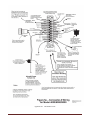
1
Delete This Page before printing!!
To Keep Page Orientation Correct
Instructions for Printing & Binding
This page gets wasted, to maintain orientation of pages throughout the manual when viewing online, To
allow viewing 2 Pages Up.
Begin printing on Page 1 (the Cover) and print both sides of paper.
Page orientation is important. This can be seen when you get to Pages 22 & 23 which should be facing you
when the Manual is open, as well as many more as you progress through the manual. This has the Narrative
and the proper Drawing facing you at the same time.
Print on 20 Lb (Min.) Premium Paper or better, Printing both sides of paper.
I prefer Spiral Bound with Clear Front Cover and Heavy Black Back Cover.
This allows the manual to be opened and folded back leaving the desired page exposed and lays flat when
opened to expose 2 pages while doing Inspections or Maintenance.
I generally get them printed at Staples or Office Depot where it costs as little as $15.00 USD per manual in
Black & White, printing only the Front Cover (page1) in Color.
Some of the pictures are in Color for the benefit of online viewing, but we print them in black & white.
Thank you for your interest in our products!
Be Safe & Have Fun!! Ed Pitman
Delete This Page before printing!!
To Keep Page Orientation Correct
0
Publication Number DF912/582 -POH&FTS rev 1 12/1/2014 mm/dd/yyyy
Pilot’s Operating Handbook
& Flight Training Supplement
Light Sport Dragonfly
SLSA 912/582
Kit ELSA 912/582
Airplane Registration Number ______________________
Airplane Serial Number _______________________
Date of Delivery _____________________
dd/mm/yyyy
This Manual only applies to SLSA Dragonfly Aircraft and ELSA Dragonfly Kits
manufactured by Pitman Air in the United States of America.
copyright Ed Pitman & Bill Moyes 2013
1
Record of Manual Revisions
Note* A current version of this manual is always available
on the internet at: http://www.pitmanair.com/dragonfly
#
dd/mm/yyyy
Revision Number & Date
Headings
Paragraph
Rev. 0 03/04/2013
Rev. 1 01/12/2014
All
Add Exemption as Appendix E
to F
Old E moved
Page numbers
All
All
All
All
Serial Number Information
PA or PAK -____ ____ ____ - ____ ____ ____
Pitman Air or Pitman Air Kit –
Engine
Example:
–
PA-582-111
Production Number
See Page 26 of this Manual “Owner/Operator Responsibilities” for details.
2
Record of Manual Revisions 2
Table of Contents
Table of Contents
Safety of Flight & Service Difficulty Report Form
Introduction 7
Documentation Recovery: 7
Quality Assurance Monitoring:
7
1 - General Information
8
6
3
1.1 Introduction to airplane.
8
1.1 Equipment List:
8
1.2 Summary of the performance specifications
2 -Operating Limitations:
3 – Emergency Procedures
4 – Normal Procedures
8
9
10
13
4.1 Preflight Check
13
4.2 Engine starting
16
4.3 Taxiing
16
4.4 Normal takeoff
17
4.5 Best Angle of Climb speed (VX)
18
4.6 Best Rate of Climb speed (VY)
18
4.9 Normal landing
18
4.10 Short field takeoff and landing procedures
18
4.11 Soft field takeoff and landing procedures
19
4.13.1 EMERGENCY PARACHUTE SYSTEM
19
4.13.2
20
AIRCRAFT DISASSEMBLY FOR TRANSPORT
5 – Performance
20
6 – Weight and Balance and Equipment List22
6.1 Weight and Balance Chart
22
6.2 Operating weights and loading (occupants, baggage, fuel, ballast)
23
6.3 Center of gravity (CG) range and determination.
23
6.3.3
Ballasting to Compensate for Light Pilot Weight Solo
24
6.3.4
AIRCRAFT SPECIFIC WEIGHT AND CG POSITION
25
7 – Description of Airplane and Systems
8 –Aircraft Handling and Servicing 27
9 – Supplements
28
26
9.4 Information Important to Owner/Operator
28
9.4.1 Owner/Operator Responsibilities (required by FAA & Consensus Standard ASTM F2245)
28
9.4.2 Modifications, Improvements or Corrections
28
9.4.3 Continued Operational Safety Reporting and Compliance
28
10
– Required Placards & Markings
29
3
Checklists (printable Sample)
32
3.1
50
Appendix A1 EIS (582 only) 33
Model 2000G 33
ENGINE INFORMATION SYSTEM
33
Grand Rapids Technologies Incorporated 33
Appendix A2 EIS 4000
912/914 only 44
Model 4000/6000
44
ENGINE INFORMATION SYSTEM
44
User’s Manual44
Grand Rapids Technologies Incorporated 44
1.
Read This First! 49
2.
An Overview of Installation & Setup 49
3.
Using the Engine Information System 49
4.
5.
6.
3.2
4.1
The Basics of the Engine Information System Operation
Before Each Flight
SET PAGES – Setting Engine Limits and other User Entries
50
51
Set Page Table of Limits. [Brackets denote Dragonfly Factory Settings] N/U = not used
52
5.1
Mounting the Instrument – Position and other considerations
54
5.2
Wiring
54
5.3
Verify the Wiring – A Quick Check
57
6.1
Initial Application of Power to the Instrument
58
6.2
Tachometer Initial Test
58
Other Checks
59
6.3
7.
8.
10.
INSTALLATION 54
Check-Out
58
Configuring the EIS for your airplane. 59
Disabling Pages ( Pitman Air disables Pages 0, 4, 6, 7, 9, 11, 12, 13, 14, & 15 )
Detailed Description of Other Functions
73
71
10.1
Flight Timer
73
10.2
Unit Temperature
73
10.3
H2O (Water Temperature Function)
73
11. Use with Precision Airmotive Eagle Engine Controller
12. Updating the EIS Software
74
13. Check Entries Message 74
14. Troubleshooting Common Problems 74
15. Warranty
75
Appendix B - Flight Training Supplement 80
73
Record of Supplement Revisions
81
1 – GENERAL
83
1.1 Read this before your first training flight
83
2
84
3
PREFACE: LIGHT SPORT AIRCRAFT
LSA TRANSITION SYLLABUS
84
4
5
STANDARD EQUIPMENT
87
6
RECOVERY PARACHUTE SYSTEM
88
7
PERFORMANCE
Appendix C Placards Diagrams (582 version)
This Page Intentionally Left Blank 92
Appendix D – Bailey Release and Tow System
90
89
93
1. General Information
93
2. Limitations
97
3. Checklists
99
4. Maintenance and Service
99
1.1 Introduction
1.2 Warnings, Cautions and Notes Explained:
1.3 Description of Bailey Release and Tow System
1.4 Perspective Views and Photos
FIGURE 1 (Bailey Release & Tow System Configuration)
93
93
93
93
93
2.1 Introduction
2.2 Installation
2.3 Loads
FIGURE 2 Knots used for Safety Links
2.4 Angles
2.5 Forces
2.6 Specifications
2.7 Period of Operations of Release, TBO and Inspection Intervals.
3.1 Pre-Flight (second person needed)
3.2 Pre-Tow
3.3 Post-Flight
97
97
97
98
98
98
98
99
99
99
99
4.1 General
4.2 Installation
4.3 Inspections
99
99
99
5. Signals and Communications for Tow Operations
101
6. Safety Bulletins
103
7. Operational and Service Difficulty Reporting
103
FIGURE 3 Common Signals
Appendix E Aero Tow Exemption 104
Appendix F Aerobatic Training Syllabus
101
108
Owner/Operator Responsibilities (required by FAA & Consensus Standard ASTM F2245-10c)
Safety of Flight & Service Difficulty Report Form
Safety of Flight & Service Difficulty Report Form
114
115
5
112
Copy this page to file Safety of Flight or Service Difficulty Report
Safety of Flight & Service Difficulty Report Form
Mail to: Pitman Air, 1840 Airport Blvd., Red Bluff, CA 96080 or Online at: www.pitmanair.com/dragonfly/
Item of Concern
Circle One
Safety of Flight
Service Difficulty
LSRI
LSRM
Reporting Party Contact Information
Name
Address
City
ST
Zip Code
Day Phone #
FAX #
email address
Check Appropriate
Owner
Operator
A&P
Other Explain:
Aircraft Specific Information
Aircraft Information
Engine Information
Make
Make
Model
Model
Serial Number
Serial Number
N-Number
Gearbox Ratio
Date of Mfg.
Propeller Mfg
Propeller Serial #
Date of Problem Discovery
dd/mm/yyyy
Description:
Use Attachments and Photo’s if Needed
Comments
Signature___________________________________________-Date_______________________dd/mm/yyyy
6
Introduction
ASTM standards used
Design & Performance and Required Equipment:
F 2245-11
Quality Assurance and Production Acceptance Tests:
F 2279-06
Continued Operational Safety Monitoring
F 2295-06
Maintenance & Inspection Procedures
F 2483-05
Pilot Operating Handbook (POH)
F 2245-11 & F 2746-09
Terminology for LSA
F 2626-07
Airframe Emergency Parachutes
F 2316-08
Kit Assembly Instructions
F2563-06
Required Product Information
F2745-11
In accordance with 14 CFR part 21.190
America’s LSA Manufacturer:
Pitman Air
1840 Airport Blvd.
Red Bluff, CA 96080
Email: [email protected]
Ed Pitman 530-945-1860 9 – 5 Pacific Time
Technical support:
Bobby Bailey 352 429 5660 Eastern Time
Rhett Radford 603 690 5200 Eastern Time
Many Airframe Parts Manufacturer:
Lite Flite Pty Ltd.
1144 Botany Road
Botany NSW 2019
Australia
Ph. +61 2 9316 5543
Fax +61 2 9316 8488
Email [email protected]
Documentation Recovery:
Contact the Pitman Air business location above or
For N Numbered Aircaft , your documentation can be obtained through the FAA
http://registry.faa.gov/aircraftinquiry/
Look up your craft by N Number and use the (obtain information) as shown below
This is the most current Airworthiness Certificate data, however, it may not reflect the current aircraft configuration. For that
information, see the aircraft record. A copy can be obtained at http://162.58.35.241/e.gov/ND/airrecordsND.asp
Quality Assurance Monitoring:
Refer to Quality Assurance Manual (QAM)
Current information can be obtained through
www.pitmanair.com/dragonfly
or
www.safetydirectives.com/dragonfly
7
1 - General Information
1.1 Introduction to airplane.
This Light Sport Aircraft is manufactured to meet the requirements United States of America Light Sport Category.
The pilot’s weight range is from 143lbs. (Standard 582) to 187 lbs. ( Standard 912) (unless ballast is utilized, see Weight
and Balance Section 6 page 20) and this aircraft when flown solo must only be flown from the front seat for weight and
balance reasons. The pilot’s weight is essential to be in the front seat to keep the aircraft balanced within its Center of
Gravity (CG) Range. (Refer to Weight and Balance Section 6, page 20.)
The pilot must have a valid Sport Pilot Certificate or higher with proper endorsements.
This aircraft must be flown and operated within the current FAA Regulations.
The Dragonfly is designed to fly with the Flaperons in permanent partial Flaps on position. The low speed capabilities of
this aircraft create a particular set of characteristics and each pilot shall become familiar with its ground handling and flight
characteristics before towing or carrying passengers.
This aircraft’s engines are not certified aircraft engines. All engines are subject to failure. This should always be considered
when choosing a flight path. The path chosen should allow for emergency landings.
Changes to the controls and control surfaces should not be attempted. There is a balance of aerodynamic forces to consider.
1.1 Equipment List:
1.1.1 Required Equipment
1.1.2.1 Flight and Navigation Instruments:
1.1.2.1.1 Airspeed indicator, (for markings refer to Section 10.1)
1.1.2.1.2 Altimeter. (in EIS Manual Appendix A of this manual)
1.1.2.2 Powerplant Instruments:
1.1.2.2.1 Fuel quantity indicator, ( Visual on Tank )
1.1.2.2.2 Tachometer (RPM) (EGT) (CHT), Coolant Temp, Hour Meter (in EIS Manual Appendix A of this manual)
1.1.2.2.3 Engine “kill” switch, Mag 1 & Mag 2 to Off Position (Master Switch OFF will not stop engine)
1.1.2.2.4 Engine instruments as required by the engine manufacturer. (in EIS Manual Appendix A of this manual)
Set EIS Warning Limits to Rotax specifications.
1.1.2.3 Miscellaneous Equipment:
1.1.2.3.1 Ballistic Recovery System SECOND CHANTZ 1100# Compressed Air Propelled
1.1.2.3.2 Bailey Release and Tow System (when used for Aero-Towing)
1.1.2.4 Safety Belts and Harnesses
1.1.2.5 ELT
AMERI-KING ELT AK-450
1.2 Summary of the performance specifications
1.2.1 Gross Weight 1080 lbs / 490 kg
1.2.2 Top speed
Cruise speed
582UL 66mph @ 6500 rpm
582UL 54mph @ 5200 rpm
& 912ULS 66 mph @ 5000 rpm
& 912ULS 54 mph @ 4300 rpm
1.2.3 Full fuel range
8
582UL - 50 sm
@ 5200rpm., 912UL 78 sm @ 4300 rpm., & 912ULS - 70 sm @ 4300 rpm
( 6 Gallon Tank ) with 30 min. reserve
1.2.4 Rate of climb
Vx Best Angle-of-Climb
582UL
912UL
912ULS
Vy Best Rate-of-Climb
1.2.5 Stall speed
37 mph ≈ 750 fpm (solo) 44 mph ≈ 350 fpm @ GROSS WEIGHT
37 mph ≈ 900 fpm (solo) 44 mph ≈ 500 fpm @ GROSS WEIGHT
37 mph ≈ 1100 fpm (solo) 44 mph ≈ 750 fpm @ GROSS WEIGHT
582UL 42 mph ≈ 850 fpm (solo)
912UL 42 mph ≈ 1000 fpm (solo)
912ULS 42 mph ≈ 1200 fpm (solo)
47 mph ≈ 350 fpm @ GROSS WEIGHT
47 mph ≈ 550 fpm @ GROSS WEIGHT
47 mph ≈ 800 fpm @ GROSS WEIGHT
30 - 38 mph
1.2.6 Total fuel capacity
6.1 gallons 5.9 useable
1.2.7 Maximum engine power output
582UL 64hp / 48kW @ 6500 rpm
912UL 80 hp / 59.6 kW @ 5600 rpm Max. Continuous HP.
912ULS 99 hp / 73.5 kW @ 5800 rpm (3 minutes Max.)
90 hp / 69 kW @ 5500 rpm Max. Continuous HP.
Refer to Graphs in Section 2.10
2 -Operating Limitations:
2.1 Airspeed Indicator speed range markings
Falcon Airspeed Indicator ASI (refer to Appendix C)
2.2 Stalling speed at maximum takeoff weight Vs 38 mph @ GROSS WEIGHT
2.3 Flap extended speed range N/A No Flaps
2.4 Maneuvering speed VA at Gross Weight 55 mph and 60 mph solo
2.5 Never exceed speed VNE 66 mph
2.6 Service Ceiling 15,000 ft.
2.7 Load factors +4G -2G
2.8 Approved maneuvers Limited Aerobatics **, These Aerobatics shall only be performed Solo, except for
training with factory test pilot.
2.8.1 Spins **
2.8.2 Loops **
2.8.3 Rolls **
** Note: Aerobatic Maneuvers limited to approved maneuvers for the Dragonfly and performed by a Pilot with proper
training in the “Dragonfly Aerobatics Course”.
** Caution: Engine is limited to positive G forces at all times. Engine damage or failure may occur if negative G forces
are held for more than a few seconds.
2.9 Fuel
Total fuel capacity 6.1 gal.
Total usable fuel 5.9 gal.
Approved types of fuel 90+ octane quality unleaded auto gasoline*
9
* refer to Rotax Operators Manual or www.flyrotax.com for current recommendations.
2.10 Maximum engine power output
Rotax 582 64hp / 48kW @ 6500 rpm
Rotax 912ULS 99 hp
Graphs produced by Rotax
Rotax 912UL 80 hp
Fuel Consumption graphs in Section 5.5 of this manual
2.11 Applicable environmental limitations
Aircraft has removable fuel tank to allow re-filling in approved area.
2.12 Daytime VFR only *unless equipped with Optional Lighting Package.
3 – Emergency Procedures
3.1 General Information,
Stall due to low airspeed
In all cases where low air speed has caused an inadvertent stall the aircraft will continue out of control until a flow of air is
re-established over the wings.
The immediate reaction must be STICK FORWARD.
Push the stick fully forward until the aircraft has recovered flying speed, and then ease back on the stick till normal flying
attitude.
Resist the temptation to pull the nose up.
Spins
NOTE: “LIMITED AEROBATICS”
** Note: Aerobatic Maneuvers limited to approved maneuvers for the Dragonfly and performed by a Pilot
with proper training in the “Dragonfly Aerobatics Course”.
** Caution: Engine is limited to positive G forces at all times. Engine damage or failure may occur if
negative G forces are held for more than a few seconds.
10
In all cases where low air speed has caused an inadvertent stall and spin, the control response reaction must be:STICK FULL FORWARD
and then
FULL OPPOSITE RUDDER
That means if you have entered a spin to the LEFT push hard on the RIGHT rudder pedal.
Once the spin has stopped, reduce power to avoid over speed, centralize the controls and gently recover from the dive.
Reset the throttle power setting as required.
3.2 Airspeeds for Emergency Procedures
Best Glide VY 42-47 mph depending upon weight
Rapid decent less than VNE 66 mph.
3.3 Emergency Checklist.
The simplicity of the Aircraft does not require an order or process during an Emergency Procedure other than normal pilot
processes of flying the aircraft and using good judgment.
3.3.1 Engine fire during start
Master switch OFF
Engine ignition to OFF
Move away and remain clear of aircraft.
3.3.2 Engine failure during takeoff
Stick Forward, Attitude to best glide speed. Vy 42–47 mph.
If the engine fails at altitudes below 100m/300ft above ground level do not attempt to restart the engine.
Conduct an emergency landing as described below:
Land into the wind, or uphill if possible, At lower than 300’ land straight ahead or slightly off to the side. Always monitor
the airspeed closely and maintain forward airspeed. Resist the temptation to pull back on the stick to stretch the glide. Do
not turn close to the ground.
The optimum glide speed with engine off is 42 mph solo to 47 mph dual. Once an adequate landing area has been reached
maintain minimum of 45mph solo to 50 dual, until about 10ft above ground. Ease back on the controls and start a flare for
landing at 3 feet AGL. With the engine idling, excess speed will quickly diminish when leveling out.
3.3.3 Loss of engine power in flight
Attitude to best glide speed. Nose down to maintain speed.
If the engine fails at altitudes above 100m/300ft above ground level, an attempt to restart can be made.
Ensure ignition is on and engage starter, ensuring the throttle is forward of the idle position. The engine will turn quicker
than on the ground due to airflow over the propeller. Closely monitor airspeed and maintain at or above 35mph. If a restart
is not possible by 100m/300ft then carry out an emergency landing as above.
3.3.4 Emergency landing without engine power
Same as 3.3.2 & 3.3.3 above
3.3.5 Precautionary landing with engine power
Use normal landing procedure or the appropriate landing procedure listed above.
3.3.6 Fire in flight
Master switch OFF
Engine ignition to OFF
Descend at less than VNE 66 mph.
11
Land at nearest reasonable site.
3.3.7 Loss of oil pressure (Not Applicable w/582)
912 - Look for safe landing spot, throttle back as soon as possible, shut engine off as soon as possible.
3.3.8 High oil pressure (Not Applicable w/582)
912 - Likely not an Emergency. However, Look for safe landing spot, throttle back as soon as possible, shut engine off as
soon as possible.
3.3.9 Emergency descent
Throttle closed
Nose down attitude of approx. 45 degrees
Descend at close to but more than VNE 66 mph
Refer to 3.3.2 for landing procedure.
3.3.10 Alternator failure
This is not an emergency situation. The engine is not affected when the electrical system is not charging. The master
switch can be turned off to conserve battery but this will shut off the EIS ( Engine Information System ) and other powered
items. . Land as soon as is practical and repair the problem.
3.3.11 Overvoltage
If voltage exceeds 16V the master switch should be turned off to prevent the battery from over-heating. Land as soon as is
practical and repair the problem. The EIS warning level should be set to 14.9 volts DC.
3.3.12 Inadvertent spin
In all cases where low air speed has caused an inadvertent stall and spin, the control response reaction must be:STICK FORWARD TO RELEAVE BACK PRESSURE that caused the Stall
and then
FULL OPPOSITE RUDDER
That means if you have entered a spin to the LEFT push hard on the RIGHT rudder pedal.
Once the spin has stopped, reduce power to avoid over speed, centralize the controls and gently recover from the dive.
Reset the throttle power setting as required.
3.3.13 Inadvertent Icing Encounter ( Carb Icing )
Structural
With the open cockpit the likelihood of inadvertent icing is minimal. Should this occur, exit the icing area
in the direction from which you came.
Carburetor
Carb Icing is extremely rare on the 582 and 912. However, our experience has shown that it can occur at
a power setting between cruise and below full throttle and outside air temperatures between 68 and 74degrees F ( 20
– 24 C ). If this occurs go to full throttle and you will hear the engine clear up within a minute. Then you can return to the
desired throttle setting and be vigilant for reoccurrence of ice.
3.3.14 Loss of primary instruments
This should not be an emergency in this aircraft. Land at an appropriate area and repair the problem.
3.3.15 Loss of flight controls.
Failure of elevator
The Horizontal Stabilizer is fixed at 13 degrees negative to the wing. Level flight can be maintained by increasing or
decreasing air speed, with throttle use & use of the trim tab.
12
Should pitch be uncontrollable after an elevator failure even after experimenting with the throttle & trim tab, shut down the
engine and operate the emergency parachute at a time that is suitable.
Failure of ailerons
The Dragonfly’s ailerons double as flaps and are in permanent flap position. Should one aileron fail take immediate steps
to balance the aircraft with the other and final balance with the rudder. Should both fail and the aircraft is uncontrollable
with the rudder then the pilot should operate the emergency parachute after shutting down the engine.
Rudder failure
Use the ailerons to steer the aircraft by gentle banking to achieve direction. Land the aircraft immediately following any
control surface failure or suspect operation.
4 – Normal Procedures
4.1 Preflight Check (The same type of inspection should be done as Post Flight Inspection)
NOTE: A Post Flight Inspection may find issues that require maintenance or repair prior to next flight.
refer to Figure 4 Pre-Flight Areas on page 13
Every time the plane is prepared for flight the entire aircraft must be subjected to a pre-flight check whereby the pilot
visually checks the aircraft to ensure that the aircraft is in a condition for “Safe Operation”.
Conduct the pre-flight check as a walk around the aircraft starting at the same point each time, to ensure that every part of
the structures, cables, attachments and components are inspected. Every part or component must be free of excessive wear,
defect, tears, cracks, etc. refer to Figure 4 Pre-Flight Areas.
4.1.1
Aircraft and engine controls
For each seat check that the rudder pedals and stick move freely into all extreme positions. Check the links and
connections on the stick and rudder to ensure that they are connected correctly and secured.
Check the condition of the seats and check that the seatbelts are securely fastened. Check that the fuel tank is securely
fastened and with the cap screwed tight and containing the sufficient amount of fuel for the intended flight time.
4.1.2
Instruments
Check the Pitot Tube orifice is clear of obstructions. (A simple test can be done to check that airspeed indicator works by
blowing from several inches away, across the Pitot Tube, NEVER BLOW DIRECTLY INTO THE PITOT TUBE as this
can permanently damage the instrument. Ensure that the indicator returns to zero position.)
Check the correct indicating positions of the other instruments.
4.1.3 Undercarriage and main wheels
Check (visually and by hand) that the tires have the correct air pressure. Check that the tires are free of any damage. Check
that the wheel nuts are in place and not loose, and that the undercarriage legs/axles are securely fastened to the fuselage.
4.1.4
Emergency parachute
Check that the emergency parachute is securely fastened to the aircraft with the cover sitting in the correct position and
with the bridle secured around the main root tube. Remove the safety pin from the release handle and stow in a secure
position. Re Insert the safety pin in Post Flight Inspection. Minimum Pressure 4200 psi
4.1.5
Left part of the wing
Remove the inspection panel behind the parachute and inspect the inside of each side of the wing ensuring that all battens
are in place and that all tubing and support cables are undamaged. Replace the inspection panel and secure using the
Velcro strips. Check that the Dacron wing surface is free of holes or other damage. Check that each end of the strut and
outside support cables are securely fastened on the fuselage, tail and wing respectively.
Check that the aileron is securely fastened to the wing and that it moves freely between the extreme positions. Check that
the linkages and connections to the control surface are securely fastened.
13
4.1.6
Engine and propeller
Check that the propeller is free of damage, especially delamination of the composite material. Check that the engine and
muffler is securely fastened to the engine assembly plate and that this is securely fastened to the aircraft. Ensure that all
safety wires are in place as required on the propeller, gearbox and engine bolts. Check that the oil tank and the radiator are
filled to proper level (overflow bottle should have fluid at minimum mark cold) and check that the ignition cables are
securely in place on the spark plugs. Insure Propeller bolts are secure, and inspect prop for damage.
4.1.7
Tail
Check that the rudder and elevator moves freely between the extreme positions.
Check that the linkage and connections for the control surfaces are securely fastened. Check (visually) that the tail wheel
tire has the correct air pressure and is free of damage. Check that the wires from the rudder pedals are connected correctly
to the steering plate. And that supporting cables are free of defect or wear.
4.1.8
Right part of the wing. Same as for the inspection of the left wing. 4.1.5 above
Inspect each side of the wing ensuring that all battens are in place and that all tubing and support cables are undamaged. .
Check that the Dacron wing surface is free of holes or other damage. Check that each end of the strut and outside support
cables are securely fastened on the fuselage, tail and wing respectively.
Check that the aileron is securely fastened to the wing and that it moves freely between the extreme positions. Check that
the linkages and connections to the control surface are securely fastened.
14
1
2
3
4
5
8
6
7
7
6
5
4
8
3
2
1
Figure 4 Preflight Areas
15
4.2 Engine starting
WARNING:
start system.
Do Not attempt Hand starting by turning the propeller is Very Dangerous. Always use the electric
FUEL: Approved types of fuel, 90+ octane quality unleaded auto gasoline* (use of 100 LL requires additional
provisions listed in current Rotax manuals)
* refer to Rotax Operators Manual or www.flyrotax.com for current
recommendations.
OIL: 582 Approved* types and brands of TCW-III mixed 50:1
912 Approved* types and brands listed in the Current Rotax 912 manuals
* refer to Rotax Operators Manual or www.flyrotax.com for current
recommendations.
STARTING THE ENGINE;
1.
2.
3.
4.
5.
6.
7.
8.
Ensure rear seat belt is fastened so that it will not fly into prop and no other item is loose that will be
drawn into the propeller stream.
Pump fuel to the carburetors by operating the squeeze bulb in the fuel line till the bulb is firm.
Ensure that the throttle is in Idle Position (Closed)
Choke on (Cold Start)
Check that prop is clear of bystanders.
(When you are ready, look both sides and call loudly
“CLEAR PROP”)
Ensure that the front of the aircraft is clear.
Operate brakes. (On)
582 Pump bulb until it beomes hard. Pump primer 2-3 times.
912 Equipped with Electric Boost Pump, run pump until fuel is seen returning to tank through the return line.
9.
Call “CLEAR PROP” to warn observers, & look to insure it is clear.
10.
Turn IGNITION Switches ON and Press Starter Switch to Start.
Normally the engine will start within 2 seconds. Do not crank the engine more than 10 seconds if it does not start.
Longer operation may overheat the starter motor.
( 582 only -- Cold conditions require more priming. Pump primer twice more and try again.)
The behavior of the engine will indicate the problem. In most cases it is too much or too little fuel to suit the temperature.
Should the engine not start after three or four attempts then it is possible that the engine is flooded with fuel.
To balance this situation, open the throttle to allow more air to be drawn in.
CAUTION: With the throttle open the aircraft may surge forward when it starts. Be ready to Close Throttle.
Operate the starter with one hand on the throttle to immediately pull the throttle back to idle or low power if the engine
starts and be ready to SWITCH OFF if an emergency arises.
When the engine starts allow it to idle at 2000 – 2200 rpm for a full minute or longer to allow the engine to reach operating
temperature. Let the engine warm up properly before applying too much power!
582 Coolant to 140 degrees F, before exceeding 3000 rpm’s.
912 Oil Temperatures to 120 degrees F, before exceeding 3000 rpm’s.
IMPORTANT NOTE: A thorough warm up is essential to the longevity to the engine life and performance.
4.3 Taxiing
The Rudder pedals operate rudder and tail wheel steering. Control is easy and turning radius is average.
Taxiing in cross wind up to 15 mph creates no problem.
Both the rudder and tail wheel turn the aircraft in the same direction.
For a left turn PUSH LEFT PEDAL
For right turn PUSH RIGHT PEDAL
Cont’d next page
16
At times Low Speed Taxiing can be improved by pulling up elevator to hold the rear wheel firmly on the ground. When
taxiing down wind keep the stick in Neutral Position.
When attempting to taxy across wind lean the stick into the wind to reduce lift on the upwind flaperon. Failure to keep the
aircraft balanced can lead to Ground Loops.
4.4 Normal takeoff
Checklist (sample)
Immediately prior to takeoff the pilot must go through the following Start Checklist:
1)
Seatbelts securely buckled
2)
Free movement of rudder pedals and stick to the extreme positions.
3)
Safety pin removed from parachute release.
4)
Sufficient fuel in tank for the intended flight time
5)
Engine warmed up sufficiently Water Temp 140 F Choke OFF
6)
Electrical instruments ON
7)
Adjust Altimeter
8)
Check wind direction.
Procedure
When the runway and the flight path approach to the runway are clear, taxi into the take off position.
Always take off into prevailing wind. Takeoffs can be conducted in cross wind conditions up to 15 mph.
Release the brakes and when the aircraft starts to roll keep the stick slightly pulled back. At 20 mph the tail wheel will lift
off. With the tail wheel 1ft off the ground keep accelerating while keeping the aircraft on a straight line with positive and
firm rudder movements. At 30 mph the aircraft will lift off in the ground effect. Pull the stick back slightly and keep the
aircraft in an even climb at a constant speed of 45-50 mph.
At an altitude of 300 feet reduce the throttle if needed and keep climbing at 40–45 mph.
In very calm conditions and after extensive experience with the aircraft the climb can be performed with a single person
onboard at 30-35 mph. At this speed the aircraft will climb best.
Important
During the climb it is imperative that the aircraft is not pulled into too a steep climb angle, the aircraft will still be
controllable but it will stop climbing. Inexperienced pilots can unwittingly bring the aircraft in such a situation especially
when flying over obstacles.
Performance values
The stated values are valid at sea level in nil wind conditions and at temperature of 60 degrees F.
The takeoff weights in the two cases are 750lb solo and 950lb two place on an even dry short grass runway.
Higher temperature, weight or altitude will require additional runway.
From a standing start the distance to take off : (distances performed by factory test pilot, results vary based on pilot skills)
582UL Solo ≈ 225ft.
Gross Weight 1080 ≈ 300 – 345 ft.
912UL Solo ≈ 215 ft.
Gross Weight 1080 ≈ 280 – 335 ft.
912ULS Solo ≈ 185 ft.
Gross Weight 1080 ≈ 245 – 300 ft.
Take off distance to clear 50ft high obstacle: (distances performed by factory test pilot, results vary based on pilot skills)
582UL Solo ≈ 650ft
Gross Weight 1080 ≈ 950ft
912ULS Solo ≈ 600 ft.
Gross Weight 1080 ≈ 790 - 825 ft.
912ULS Solo ≈ 450 ft.
Gross Weight 1080 ≈ 590 - 605 ft.
Take off speed:
Solo
Two place
38 mph
42 mph
Speed on clearing a 50ft obstacle:Solo
37 mph
Two place
44 mph
17
4.5 Best Angle of Climb speed (VX)
582UL
912UL
912ULS
37 mph ≈ 750 fpm (solo) 44 mph ≈ 350 fpm @ GROSS WEIGHT
37 mph ≈ 900 fpm (solo) 44 mph ≈ 500 fpm @ GROSS WEIGHT
37 mph ≈ 1100 fpm (solo) 44 mph ≈ 750 fpm @ GROSS WEIGHT
4.6 Best Rate of Climb speed (VY)
582UL 42 mph ≈ 850 fpm (solo) 47 mph ≈ 350 fpm @ GROSS WEIGHT
912UL 42 mph ≈ 1000 fpm (solo) 47 mph ≈ 550 fpm @ GROSS WEIGHT
912ULS 42 mph ≈ 1200 fpm (solo) 47 mph ≈ 800 fpm @ GROSS WEIGHT
4.7 Cruise (Dragonfly is inefficient at higher speeds.)
582UL
Cruise at ≈ 4600-5000 rpm will give ≈ 45-50 mph solo
Consumption at cruise is ≈ 4.0 US gal per hour
Range is approximately ≈ 45 - 50 miles (no wind 500’ MSL with 30 min reserve)
912ULS & 912UL
Cruise at ≈ 4100-4300 rpm will give ≈ 49 - 54 mph solo
Consumption at cruise is ≈ 2.8 US gal per hour
Range is approximately ≈ 70 - 80 miles (no wind 500’ MSL with 30 min reserve)
4.8 Approach ( Normal Approach Speed is 50 - 55 mph.)
Always land into the prevailing wind when possible
At idle the airspeed should always be kept at least at 38 mph. At half throttle the airspeed should always be kept at least at
40 mph.
Conduct a conventional approach to the runway with a downwind leg, a base leg and a final approach while observing any
special landing pattern rules that may be in force at the airfield. Always keep a good lookout for other aircraft during the
landing
Under normal conditions make the final approach with ≈ half throttle. Always make the final approach high with enough
height to make the runway even with loss of the engine.
4.9 Normal landing
When the aircraft is 3 feet above the ground pull the stick back slowly and bring the aircraft into level flight above the
ground while using the throttle to keep the aircraft at constant altitude and a speed of ≈ 38 mph. Then ease the throttle
back while pulling slowly back on the stick and bring the aircraft to the ground gently. The correct landing speed is ≈ 28 35 mph. When the aircraft touches down pull the throttle all the way back and bring the aircraft to a halt by using the
brakes.
When the Dragonfly is on the ground with all 3 wheels the wing has an angle of incidence of 13 degrees.
This is sufficient angle of attack to lift the aircraft off the ground at flying speed. Therefore when you wish to land observe
the old proverb “You don’t land a plane, you fly it till it stops flying”
Hold the plane off the ground till the tail wheel touches first. Then reduce throttle.
The aircraft will come to a halt quickly if landed in this fashion as the wing is at a high angle of incidence and creates
maximum drag.
Experience will allow you to land by greasing it in on all three wheels together or front wheels first.
4.10 Short field takeoff and landing procedures
Take-off Short Field
1) Position at farthest point back on runway possible,
2) Hold Brakes with stick all the way back.
3) Increase power to maximum and release brakes.
18
4) As speed increases stick goes smoothly to neutral position to reduce angle of attack. At Vx rotate nose up for take-off
and maintain until clear of obstacle then accelerate to Vy
Landing Short Field
1) Position for Normal landing till finial.
2) Carry extra speed and a steep approach angle with your aiming point just a little short of your intended touch down
target.
3) Throttle should be closed as soon as touch-down target is assured.
4) Use a forward slip if you are a little high or a slightly more shallow approach if low. Always maintain some extra
speed thru the gradient as the Dragonfly’s High Lift, High Drag Airfoil can lose speed quickly.
5) Round out two to three feet above the landing surface.
6) Pull back on the elevator just enough to maintain level flight. As the airspeed bleeds
off the Dragonfly will start to settle.
7) Pull full back elevator. Keeping the stick full back after touch-down to put steering weight on the tail wheel,
and apply brakes as necessary.
4.11 Soft field takeoff and landing procedures
Take-off Soft Field
1) Keep aircraft in motion and avoid use of the brakes.
2) When aligned with the center of the runway, go to full power smoothly.
3) With stick neutral or slight back pressure maintain near 3 point attitude until take-off. Lower nose and accelerate to Vy.
Landing Soft Field
1) Position for Normal landing through the Finial approach.
2) After rounding out leave the throttle open for 2,000 to 2,200 RPM’s. when the Dragonfly begins to
settle.
3) Stop pulling back on the elevator and allow the main landing gear to touch down. Close the throttle and allow the tail
wheel to land.
4) Maintain enough taxi speed to keep from sinking into the soft field. Brakes should be used only as a
last resort.
4.12 Aborted landing procedures
Add power and go to best rate of climb maintain runway heading and re-enter pattern.
4.13 Any other useful pilot information
Because the Dragonfly is light and high in drag, speed is lost quickly when thrust is lost. Nose Down Pitch Attitude must
be addressed much more quickly than conventional aircraft .
4.13.1 EMERGENCY PARACHUTE SYSTEM
The manufacturer’s recommendations for mounting and maintaining the emergency parachute must always be adhered to.
The parachute has its own operations manual that is supplied separately with this aircraft.
It is especially important to protect the parachutes from moisture and heat. If the parachute ever gets moist or wet it must
be opened, dried and repacked by a “Qualified Person”.
Parachutes with rocket deployment have a limited life span of the rockets.
The parachute and rocket should be returned to Manufacturer each 5/6 years for inspection and repack. See manual.
There is a safety pin to prevent accidental deployment. This must be removed before each flight and replaced after each
flight.
Before each flight check that the parachute is securely mounted on the aircraft and that the bridle is securely attached to the
main root tube.
** Refer to current SECOND CHANTZ Recovery System Manual
19
4.13.2 AIRCRAFT DISASSEMBLY FOR TRANSPORT
Transport on a trailer requires a trailer of sufficient size to accommodate the aircraft and provide protection while the
aircraft is in transit. It also requires cradles or support means to avoid damage to wing and control surface fabric and to
prevent impact damage to the airfoil surfaces.
1:
2:
3:
4:
5:
6:
7:
8:
9.
10.
11.
12.
Remove propeller6 mounting bolts
Disconnect throttle and carburetors
Disconnect Fuel Line and primer
Disconnect multi plug wiring
Disconnect starter cable
Remove gap cover and wing straps
Remove engine by removing 6 bolts through the Lord isolation mounts
Disconnect rear wing to tail cables at tail and fuselage
Disconnect Aileron push rods and Aileron torque tube
Disconnect struts at bulkhead and jury struts.
Remove 4 wing mounting bolts and remove wings with struts attached to wings.
Fold jury struts to main strut.
Fold main struts to wings.
Mount wings on trailer.
Disconnect horizontal stabilizer support cables by removing AN3 bolt at Stabilizer ends.
Disconnect elevator connecting bracket.
Horizontal stabilizer and elevator will fold up to the vertical stabilizer and Rudder.
Tie both the horizontal stabilizer tips together.
The fuselage and cockpit is easily handled and mounted on or in a trailer.
NOTE: Some of this procedure can be avoided by leaving the engine and propeller mounted if your
trailer
has sufficient space. However the engine must be supported in the trailer when the
wings and struts are removed.
For assembly reverse the procedure. Two experienced people can assemble a Dragonfly in 20 min
Maintenance:- refer to Maintenance Manual for instructions for “Continued Airworthiness”.
5 – Performance
5.1 Takeoff total distance over a 50 foot obstacle (distances performed by factory test pilot)
582UL Solo ≈ 650ft
912ULS Solo ≈ 600 ft.
912ULS Solo ≈ 450 ft.
Gross Weight 1080 ≈ 950ft
Gross Weight 1080 ≈ 790 - 825 ft.
Gross Weight 1080 ≈ 590 - 605 ft.
5.2 Landing total distance over a 50 foot obstacle (distances performed by factory test pilot)
582UL
Solo ≈ 500ft
912UL & 912ULS Solo ≈ 525 ft.
Gross Weight 1080 ≈ 590 - 655 ft.
Gross Weight 1080 ≈ 590 - 655 ft.
5.3 Rate of climb
582UL
912ULS
42 mph ≈ 900 fpm (solo)
42 mph ≈ 1200 fpm (solo)
47 mph ≈ 350 fpm @ GROSS WEIGHT
47 mph ≈ 800 fpm @ GROSS WEIGHT
5.4 Cruise speeds
582UL
Cruise at ≈ 4600-5000 rpm will give ≈ 45-50 mph solo
Consumption at cruise is ≈ 4.0 US gal per hour
Range is approximately ≈ 45 - 50 miles (no wind 500’ MSL with 30 min reserve)
912ULS
Cruise at ≈ 4100-4300 rpm will give ≈ 49 - 54 mph solo
Consumption at cruise is ≈ 2.8 US gal per hour
Range is approximately ≈ 70 - 80 miles (no wind 500’ MSL with 30 min reserve)
20
5.5 582UL RPM setting and fuel consumption (graph from Rotax 582 Manual)
912ULS RPM setting and fuel consumption (graph from Rotax 912 Manual)
Power output graphs in Section 2.10 of this manual
Our tests & use have shown 582 ≈ 4 gph @ 5000 - 5200 rpm cruise (results may vary)
912 ≈ 2.3 – 2.6 gph @ 4100 – 4300 rpm cruise (results may vary)
21
6 – Weight and Balance and Equipment List
6.1 Weight and Balance Chart
22
6.2 Operating weights and loading (occupants, baggage, fuel, ballast)
The CG must never be further FORWARD than 76.1” in. from the Datum nor further AFT than 83” in. from the
Datum.
The aircraft must never be flown solo from the back seat.
The pilot minimum weight of 60 kg in the front seat is necessary to keep the aircraft in its CG range.
The CG range as a percentage of the chord of the wing is from 35.7% with the lightest pilot to 26.1% with the heaviest
pilot.
The figures shown are typical of a Dragonfly fitted with a 582 liquid cooled Rotax engine. The limiting figures are still
valid if the aircraft is fitted with other engine types. Reference should be made to the aircraft specific figures recorded in
Section 6.3.4 Page 22
The empty weight CG should be 95.9in from the Datum or 55.6% of the MAC.
6.3 Center of gravity (CG) range and determination.
The weight and position of the center of gravity (CG) of the empty aircraft must be established to conduct load sheet
calculations. The aircraft must be weighed and measured in a fixed position and attitude and in windless conditions with
wings level. Use a plumb line to project the following positions to the ground for measurements. The Datum is the point
from which all measurements are taken and for the Dragonfly is the nose or cockpit front cross tube. The attitude selected
is to raise the tail wheel till the Horizontal Stabilizer is level by measurement with a spirit level. (See fig. 2) 6.1 The
weights and measurements are recorded in this position and results as follows; - (note typical aircraft) Use only lbs. and
inches, Metric Units must be converted first.
The Mean Aerodynamic Chord (MAC) is calculated by adding the wing and flaperon area and divide by span.
MAC
1.
2.
3.
4.
5.
6.
7.
=
AREA =
183.10 ft sq
MEAN SPAN 34.08ft
DATUM
Pilots Pelvis position
Front Axle
Leading Edge of Wing
Fuel Tank Center
Rear Seat Pelvis position
Tail Wheel Axle
-
=
5.37ft / 64.50in
Cockpit front cross tube
Pilot
CG
Front Wheels
Co Pilot
0.00
35.0in
50.0in
60.0in
60.0in
82.0in
196.0in
CG
EMPTY WEIGHT MEASURED AS FOLLOWS and the Moment Arm from DATUM used to calculate moments. (Note –
these readings for an Example Only of typical aircraft, your aircraft may vary!)
Empty Weight Mass
Front Rt. Wheel
Front Lt Wheel
Rear Wheel
Total Weight
179.0lb
174.5lb
162.0lb
515.5lb
CG from Datum =
Moment =
Mass
Moment Arm
50.0in
50.0in
196.0in
Total Moments
Moments
49420in lb
=
515.5lb
95.90in
8950in lb
8718in lb
31752in lb
49420in lb
The Leading Edge of the wing is 60.0in aft of Datum. The empty weight CG position from the Leading Edge is then:95.90in – 60in
As a percentage of MAC
=
35.9in
35.9
64.5
=
0.556
55.6%
23
6.3.1
MAX. AFT CG WITH 133lb PILOT AND 11lb FUEL
(example)
Aircraft
Fuel
Pilot
CG
Weight
Arm
Moment
515lb
11lb
133lb
659lb
95.9in
60.0in
35.0in
49388.5 in lb
660.0 in lb
4655.0 in lb
54703.5 in lb
=
MOMENT
MASS
=
54703
659
=
83in
As a percentage of MAC
83
- 60
6.3.2
=
23
=
23
=
0.357
MAC
64.5
CG WITH MAX FUEL & TWO 90 KG / 199 lb. PILOTS
=
35.7%
(example)
Weight
Arm
Moment
Aircraft
Fuel
Pilot
Co Pilot
=
=
=
=
515lb
33lb
199lb
199lb
946lb
95.9in
60.0in
35.0in
82.0in
49388.5 in lb
1989.0 in lb
6965.0 in lb
16318.5 in lb
74660.5 in lb
CG
=
MOMENT
MASS
=
18.92
MAC
18.92
64.5
74660
946
=
78.92in
As a percentage of MAC
78.92 – 60
6.3.3
=
=
=
.293
=
29.3%
Ballasting to Compensate for Light Pilot Weight Solo
582 will have minimum front pilot weight of 138# unless ballast is added to the lower front section of upper cockpit
tube DFC 004 and/or DFC 005, near the rudder pedals. With 11 pound ballast in place, minimum pilot weight solo
is 120 lbs. Any pilot weight less than 140 lbs, must accommodate with ballast as shown with this formula, 140-(pilot
weight) * .61 = ballast needed. i.e. pilot weighs 98 lbs., then (140-98)*.61= 25.62 lbs of ballast required.
912 will have minimum front pilot weight of 175# unless ballast is added to the lower front section of upper cockpit
tube DFC 004 and/or DFC 005, near the rudder pedals. With 32 pound ballast in place, minimum pilot weight solo
is 120 lbs. Any pilot weight less than 175 lbs, must accommodate with ballast as shown with this formula, 175-(pilot
weight) * .59 = ballast needed. i.e. pilot weighs 98 lbs., then (175-98)*.59= 45.43 lbs of ballast required.
Ballast Location: Place ballast in the form of Ankle weights from Wal Mart. These can Velcro to the very front of
the pilot cage near the down tube connection by rudder pedals. These should rest the weight on the foot rest but be
wrapped around cockpit tube DFC 004 and/or DFC 005
24
Make copies of this page for calculation worksheets
6.3.4
AIRCRAFT SPECIFIC WEIGHT AND CG POSITION
The CG must never be further FORWARD than 76.1 in from the Datum, nor further AFT than 83in from the Datum
Dragonfly Serial No:
Weight at left main wheel:
Weight at right main wheel:
Weight at tail wheel:
Empty weight with standard equipment:
Maximum takeoff weight:
Maximum load:
Empty weight CG. position
CG position % MAC
1080
lb
lb
lb
lb
lb
lb
inch
MAC
Date:
Inspector:
6.3.5
Load Sheet
EMPTY WEIGHT CALCULATIONS
WEIGHT
lb
Left Front Wheel
MOMENT ARM
inch
50
Right front Wheel
50
Rear Wheel
196
Fuel
60
Pilot
35
Co-Pilot
82
MOMENT
In/lb
Installed Equipment Totals
Totals W =
CG position M/W
Totals M =
CG =
6.4 Installed optional equipment list affecting weight and balance or a reference as
to where this information can be found.
Item
Totals to use above =
Location Inches from Datum
Do Not total these
*
Sum:
25
Weight
=
Sum:
Moment
7 – Description of Airplane and Systems
7.1 General
High Wing, High Drag, Tail Dragger, Open Cockpit, 2 Place, Pusher.
7.2 Airframe
Aluminum Tube & Fabric, Cable braced, Bolt Fastener Construction
7.3 Flight controls
Junker Style Ailerons, Conventional Stick & Rudder, using Push Rods, Bell-Cranks and Cables for operation
7.4 Instrument panel
Side mounted in fairing,
Engine Information System (EIS) w/ Warning Light refer to Appendix’s A1(582) or A2 (912) for details
Standard 2 1/4” or 3 1/8” Falcon 0 – 80 mph Airspeed Indicator (for markings refer to Section 9.1 or Appendix C)
Rearview Mirror
7.5 Flight instruments
Airspeed Indicator (for markings refer to Section 9.1 or Appendix C)
Altimeter in EIS
7.6 Engines
Rotax 582UL 65 hp.
Mod 99, 2 Cylinder, 2 Cycle, Dual CDI ignition, Water Cooled, w/ 4:1 reduction Model C Gearbox,. or
Rotax 912UL 80 hp.
4 Cylinder, 4 Cycle, Dual CDI ignition, Water Cooled heads, w/ 2.24:1 Reduction Gear Drive or
Rotax 912ULS 100 hp.
4 Cylinder, 4 Cycle, Dual CDI ignition, Water Cooled heads, w/ 2.43:1 Reduction Gear Drive
**Refer to Engine Operating procedures in the Rotax Operators Manual
7.7 Propeller
582UL Bolly BOS3 72x60 SR 4 blade or Kiev Prop 71.5” 3 blade CW
912UL & 912ULS Kiev Prop 71.5” 3 blade CCW or Powerfin 72” 3 blade Type F.
7.8 Fuel and Fuel capacity
Capacity 6 US Gallons
582 90+ Octane Unleaded Auto Gas Premix 50:1 TCW-III 2 Cycle Oil
912UL 85+ octane unleaded auto gas, (100 LL may be used, but check provisions in Rotax Manuals.)
912UL 91+ octane unleaded auto gas, (100 LL may be used, but check provisions in Rotax Manuals.)
7.9 Oil
582 Approved* types and brands of TCW-III mixed 50:1
912 Approved* types and brands listed in the Current Rotax 912 manuals
* refer to Rotax Operators Manual or www.flyrotax.com for current Oil recommendations.
7.10 Operating Weights and Loading
Refer to Section 6 Weight and Balance Information
26
8 –Aircraft Handling and Servicing
8.1 Introduction
Refer to Rotax Manuals for information regarding Engine and Gearbox.
8.2 Ground Handling
Pulling by hand using the rudder pedals give steering ability to the pulling and pushing by controlling the tail-wheel
alignment..
Pushing backwards - Hold rudder pedals forward firmly and tail wheel will release and turn backwards.
Lifting Wing to lift wheel off the ground - Should be done “BY HAND” at the front strut and wing attachment point.
8.3 Towing Instructions (Ground)
When towing with equipment like a Golf Cart
Attach rope to Datum Point at intersection of nose tubes
Tow Gently with a Competent Person in the Cockpit for Steering and Braking Operation
8.4 Tie-Down Instructions
Wings - Tie down at the top of front strut where it intersects with the wing There is a Tie-Down Loop.
Tail - Tie-Down Loop near rear wheel. or Choose a solid point in the tail where tie-down rope or chain will not damage
the aircraft if pulled hard.
Note: DO NOT use the “Aero Tow Release Arm” or “Release Mechanism” to tie down.
8.5 Servicing, Fuel, Oil, Coolant, and other operating fluids,
Airframe - Hinge Points of Controls, Push Rod Guides and Cables should be lubricated with a PTFE “Dry
Lubricant” Product like “Tri-Flow” or Ace Hardware, Sherline Products PTFE Dry Lubricant “Super Lube”
So that it will not attract and hold dust and dirt.
Rotax Engine - Refer to Rotax Owners Manual furnished with the Aircraft
Or online at www.flyrotax.com
8.5.1 Approved Fuel Grades and Specifications
Refer to Rotax Owners Manual furnished with the Aircraft
Or online at www.flyrotax.com
High Octane (90+), Quality Brand, Unleaded Auto Gas. 10% Ethanol is allowed, However, Gasoline containing Methanol
should never be used.
8.5.2 Approved Oil Grades and Specifications
Refer to Rotax Owners Manual furnished with the Aircraft
Or online at www.flyrotax.com
2 Cycle TCW III oil.
8.6 Cleaning and Care
DO NOT use alkali base cleaners on fabric or aluminum
Fabric surfaces - Mild Cleaners like “Dawn Dish Soap” can be used
Metal Surfaces - WD-40 or similar light lubricant and NON ABRASIVE “Scotch Pad” or plastic bristled brush.
27
9 – Supplements
9.1 Additional Information
Rotax Engines - Refer to Rotax Owners Manual furnished with the Aircraft
And Rotax Maintenance Manual which can be down loaded
Online at www.flyrotax.com
EIS (Engine Information System) - refer to Grand Rapids Technologies Inc. EIS Manual Appendix A of this manual.
9.2 Operation of Equipment or Accessories
9.2.1 EIS refer to Appendix A
9.2.2 Bailey Release and Tow System Appendix D
9.3 Airplane Flight Training Supplement (FTS)
Located in Appendix B of this manual
9.4 Information Important to Owner/Operator
9.4.1 Owner/Operator Responsibilities (required by FAA & Consensus Standard ASTM F2245)
1) Each Owner/Operator of a LSA shall, Read and Comply with the Maintenance and Continued Airworthiness
Information and Instructions provided by the manufacturer.
2) Each Owner/Operator of a LSA shall, be responsible for providing the manufacturer with current contact
information where the manufacturer may send the owner/operator supplemental notification bulletins.
3) The Owner/Operator of a LSA shall, be responsible for notifying the manufacturer of any safety of flight issue or
significant service difficulty upon discovery.
4) The Owner/Operator of a LSA shall, be responsible for complying with all manufacturer issued Notices of
Corrective Action and for complying with all applicable Aviation Authority Regulations in regard to maintaining the
Airworthiness of the LSA.
5) An Owner of a LSA shall, ensure that any needed corrective action be completed as specified in a notice, or by the
next scheduled Annual Inspection as specified in the Notice..
6) Should an Owner/Operator not comply with any Mandatory Service Requirement, the LSA shall be considered not
in compliance with applicable ASTM standards and may be subject to Regulatory Action by the presiding Aviation
Authority (FAA).
9.4.2 Modifications, Improvements or Corrections
Modifications can only be done with an LOA (Letter of Authorization) from the manufacturer. Any modifications
or modifications to the aircraft without an LOA may result in the loss of the Airworthiness Status of the Aircraft.
9.4.1.1 Safety Directives (SD) (similar to, but not equal to, AD’s “Airworthiness Directives”.)
The manufacturer may issue one of three types of Safety Directives:
A Safety Alert (SA) - for conditions that require immediate action and instructions
B Service Bulletin (SB) - for conditions that don’t require immediate action but have a recommended future action
C Notification (N) - which doesn’t necessarily recommend future action, but is primarily for promulgation of Continued
Airworthiness Information.
9.4.3 Continued Operational Safety Reporting and Compliance
Owners have a Responsibility to report any Safety Concerns, Maintenance Problems and/or Equipment and /or Part
Failure directly to the manufacturer as soon as practical.
28
9.4.3.1 Each owner/operator of a LSA shall read and comply with the maintenance and continued airworthiness
information and instructions provided by the manufacturer.
9.4.3.2 When the manufacturer issues one of these directives, it will include information on exactly what needs to be done,
by whom, how, and what parts and tools are needed. Aircraft logbooks must be updated to show completion of any Safety
Directive. Proper Compliance with Safety Directives is MANDATORY.
9.4.3.3 The owner/operator of a LSA shall be responsible for complying with all manufacturer issued notices of corrective
action and for complying with all applicable aviation authority regulations in regard to maintaining the airworthiness of the
LSA.
9.4.3.4 An owner of a LSA shall ensure that any needed corrective action be completed as specified in a notice, or by the
next scheduled annual inspection.
9.4.3.5 Should an owner/operator not comply with any mandatory service requirement, the LSA shall be considered not in
compliance with applicable ASTM standards and may be subject to regulatory action by the presiding aviation authority.
9.4.3.6 Each owner/operator of a LSA shall be responsible for providing the manufacturer with current contact information
where the manufacturer may send the owner/operator supplemental notification bulletins.
9.4.3.7 The owner/operator of a LSA shall be responsible for notifying the manufacturer of any safety of flight issue or
significant service difficulty upon discovery.
9.4.4 Owner Change of Address Notice
In order to continue the airworthiness of each aircraft in accordance with the Quality Assurance & Continued Airworthiness Procedures,
the Owner shall notify the manufacturer within 30 days of permanent change of address and other contact information. This
information is held private and not shared with anyone outside the company, except the FAA and Quality Assurance Monitoring Firm
during audits on a visual level only.
We Need:
Owners Name
N Number
Aircraft Serial Number
Previous Address
w/ City, ST Zip Country
New Address
w/ City, ST Zip Country
Phone Numbers
This can be done by Mail to:
Pitman Air
Ed Pitman
1840 Airport Blvd.
Red Bluff, CA 96080
Or on our website:www.pitmanair.com/dagonfly
10 – Required Placards & Markings
10.1 Airspeed Indicator Falcon 0-80 mph 2 1/4” or 3 1/8” 0-80 mph
a. Minimum Controllable Airspeed Range ( Light Green Arch ) 30 – 38 mph
b. Normal Operating Range ( Green Arch ) 38 - 55 mph
c. Caution Range ( Yellow Arch ) 55 – 66 mph
d. Never Exceed Speed Vne ( Red ) 66 mph
10.2
10.3
10.4
10.5
Throttles Open / Close Arrows
Fuel Tank Premium Unleaded Premix 50:1 2 Cycle TCW-III
Master Switch On/Off
Electrical Box
Mag 1 On/Off
Power On/Off
Mag 2 On/Off
Starter Push to Start
10.6 Fuses EIS Fuse 5 amp & AUX 5 amp
10.7 Tire Pressure on Rim “ Inflate 20 psi Max.”
10.8 Gearbox GEAR OIL 75W – 140
10.9 Passenger Warning Standard 1” x 3 ¼” Warnings from Aircraft Spruce : Special “Light Sport” or
“Experimental” as appropriate.
10.10 “Light Sport” or “Experimental”
29
Abbreviations:
AOI — Aircraft Operating Instructions
C — Celsius
CAS — Calibrated air speed
cm — Centimeter
cm3 — Centimeter Cube
cu. in — Cubic Inches
F — Fahrenheit
ft — Feet
ft. lbs — Foot Pounds
FTS — Flight Training Supplement
Hg — Mercury
HP — Horse Power
hr(s) — Hour(s)
IAS — Indicated Air Speed
in — Inch
in. lbs — Inch Pounds
ISA — International Standard Atmosphere
Kg — Kilogram
km/hr — Kilometers per hour
kt(s) — Nautical Mile per Hour (knot) (1 nautical mph = (1852/3600) m/s)
kW — Kilowatt
lb(s) — Pound(s) (1 lb = 0.4539 kg)
m — Meter
Max — Maximum
mb — Millibar’s
Min — Minimum
min — Minute(s)
MIP — Maintenance and Inspection Procedures
mm — Millimeter
MPH — Miles per hour
MTOW — Maximum Take-Off Weight
N — Newton
Nm — Newton Meter
PIC — Pilot In Command
POH --- Pilot Operating Handbook in lieu of AOI
psi — Pounds per Square Inch gage pressure
RPM — Revolutions Per Minute
s — Seconds
SI — International System of units
sq. ft — Square Feet
sq. m — Square Metre
TOSS — Take Off Safety Speed
Va — Maneuvering Speed
Vc — Operating Cruising Speed
Vdf — Demonstrated Flight Diving Speed
30
Vh — Maximum Sustainable Speed in straight and level flight
Vne — Never Exceed Speed
Vso — Stalling Speed, or the minimum steady flight speed in the landing configuration
Vs1 — Stalling Speed, or the minimum steady flight speed in a specific configuration
Vt — Maximum Glider Towing Speed
Vx — Speed at which Best Angle of Climb is achieved
Vy — Speed at which Best Rate of Climb is achieved
W — Empty Weight (including required minimum equipment, unusable fuel, maximum oil, and where appropriate,
engine coolant, and hydraulic fluid)
Units:
Speed:
Kts (Knots) = 1.15 mph (miles per hour) = 1.84 km/hr 1 km/hr = 1.6 MPH
Pressure:
PSI = Pounds per Square Inch in
Hg = inches of Mercury
mb = millibar
Distances:
in. = inches = 25.4 millimeters
ft = foot (feet) = .305 meters
Weights:
Kg = kilograms = 2.2 lbs = 2.2 pounds
Misc.
1 Pound (Ib) = 0.4536 Kilogram (kg)
1 Pound per sq in (psi) = 6.895 Kilopascal (kPa)
1 Inch (in) = 25.4 Millimeters (mm)
1 Foot (ft) = 0.3048 Meter (m)
1 Statute mile = 1.609 Kilometers (km)
1 Nautical mile (NM) = 1.852 Kilometers (km)
1 Millibar (mb) = 1 Hectopascal (hPa)
1 Millibar (mb) = 0.1 Kilopascal (kPa)
1 Imperial gallon = 4.546 Liters (I)
1 US gallon = 3.785 Liters (I)
1 US quart = 0.946 Liter (I)
1 Cubic foot (ft3) = 28.317 Liters (I)
1 Degree Fahrenheit (F) = (1.8 X C)+32
1 Inch Pound (in Ib) = 0.113 Newton Meters (Nm)
1 Foot Pound (ft Ib) = 1.356 Newton Meters (Nm)
31
Checklists (printable Sample)
This Checklist can be copied,
cut around outside border,
folded back in the middle,
then laminated, to carry on Aircraft
32
Appendix A1 EIS (582 only)
Model 2000G
ENGINE INFORMATION SYSTEM
With GPS Interface
Grand Rapids Technologies Incorporated
3133 Madison Ave SE
Grand Rapids, MI 49548
(616) 245-7700 Fax (616) 245-7707
Rev 07/31/01
Introduction - The Importance of the Engine Information System
Two-stroke engines are lightweight and powerful, making them ideally suited for ultralight aircraft. Their only
potential weakness is their intolerance for operating outside their strict temperature limits. Exceeding these
limits can cause engine damage in as little as tens of seconds. The EIS greatly overcomes this weakness by
continuously monitoring all critical engine parameters, and alerting you with a bright red flashing light should
damaging engine conditions develop. With this close monitoring it is nearly impossible to knowingly exceed
these limits, making the two-stroke engine well suited as an ultralight aircraft engine.
Understanding EGT and CHT - Why they are critical to safe engine operation.
The need for monitoring engine RPM and coolant temperatures (water-cooled engines) is obvious to most pilots.
The tachometer gives you a measure of the power being produced, and allows you to keep RPM within limits to
prevent damage from mechanical stresses that result from high RPM. The coolant temperature allows detection
of high engine temperatures that could result in thermally induced mechanical damage due to insufficient
cooling. But often EGT and CHT measurements are often misunderstood. They perform very separate and
distinct roles.
Why monitor Exhaust Gas Temperature (EGT)?
EGT reflects the ratio of fuel to air being provided to the cylinder. The leaner the mixture, the higher the EGT.
EGT does not provide any indication of how well the engine is being cooled. (This is the job of coolant and
CHT.)
Internal parts (such as the piston) of all two-stroke engines will be damaged if they are operated with an EGT
that is too high. Damage can occur in a matter of tens of seconds or less if EGT limits are exceeded.
What causes a high EGT?
A lean fuel/air mixture will cause high EGT. This can be caused by:
Misadjusted, or a problem with, the carburetor
33
Too little load on the engine, such as an under pitched propeller. (This also results in unusually high engine
RPM).
A problem with fuel delivery to the engine, such as a clogged fuel line or filter, a malfunctioning fuel pump, etc.
Unbalanced (unequally opening) carburetors will cause one cylinder to operate with a higher EGT.
Cooler ambient temperatures and lower altitudes. An engine set up for operation in Denver (5000 feet above sea
level) will operate at higher EGTs when operated at sea level.
What do you do when you get a high EGT alarm.
If possible, reduce engine power. If high EGTs persist, be prepared for the possibility of sudden engine
stoppage!
If not possible to reduce power, try going to full power. The carburetor provides the leanest mixture (and highest
EGTs) around mid power. Going to full power will normally reduce the EGTs, assuming the engine is otherwise
functioning normally.
Why monitor Cylinder Head Temperature (CHT) and Coolant Temperature?
Both CHT and coolant temperature reflect how well the engine is being cooled.
They revel problems association with insufficient cooling, such as poor airflow over the engine and/or radiator,
lack of coolant, loose fan belts, etc.
They do not provide any indication of the mixture being too lean, and thus can not give any warning about
excessive internal engine temperatures. (This is the job of EGT.)
For air-cooled engines, CHT is the only means to measure how well the engine is being cooled.
For water-cooled engines, CHT allows detection of uneven coolant flow, and provides earlier warning to loss of
coolant than water-temperature.
Exceeding these limit may result in damage, but not nearly as quickly as exceeding EGT limits.
What causes high CHT and Coolant Temperatures?
High power settings and high ambient temperatures.
Problems with the engine's cooling system.
What to do when you get a high CHT and/or Coolant alarm?
Reduce engine power as soon as practical.
Reduce the load on the engine by reducing the climb rate.
If normal temperatures can not be achieved with these actions, land as soon as practical and safe and investigate.
Can only EGT or CHT/Coolant Temperature be monitored?
No. Remember that EGT reflects the fuel/air ratio, and the internal temperatures of the engine. The CHT and
coolant reflect how well the engine is being cooled, and the overall temperature of the engine. When an engine
is damaged due to high EGT (lean mixture), it is typical for the CHT or coolant temperature to remain normal.
When an engine is damaged due to high CHT and/or coolant (lack of cooling), it is typical for the EGT to
remain normal. They measure different aspects of the engine that do not necessarily react together.
Operating Instructions for the EIS Model 2000G
The Model 2000 is specifically designed for the powered-parachute type aircraft, requires very little input from
the pilot.
Before using the Model 2000 for the first time:
Set the units for temperature, altitude, and fuel quantity (if used) as desired. The instruments are set at the
factory to Fahrenheit, Feet and Gallons for temperature, altitude, and fuel respectively.
Read the section on “Automatic Altimeter” operation. Set this as desired.
Engine limits are pre-set at the factory. You may review these limits, and change them at any time if you desire.
All settings in the instrument may be set back to the initial factory settings by holding the right button
(“Display”) when turning on the instrument.
34
Before Each Flight:
1. If the altimeter is operated in the Manual mode, set the altimeter appropriately. If the altimeter is set to the
automatic mode, no action is required.
Detailed Description of the Features:
Automatic/Manual Altimeter Setting.
The altimeter can be set manually by the pilot, or automatically the by the instrument. This option is selected on
the “SET LIMITS” pages.
Automatic Altimeter Operation In this mode the altimeter will automatically be set to zero at 45 and 75 seconds after the instrument is turned
on, if the engine is running and has not exceeded 4100 RPM. If the RPM goes above 4100, the instrument
assumes the airplane is in the air, thus does not alter the altimeter setting.
The intent of this logic is to allow the instrument to automatically zero the altimeter when the engine is being
warmed up on the ground, but hopefully not cause the instrument to reset the altimeter when the instrument is
turned on and off in the air. The automatic mode of the altimeter should not be used when:
You wish to set the altimeter to the airport’s elevation. This is often done when flying to another airport,
especially when the airports are at different elevations.
If you anticipate turning off the instrument in flight, and then turning it back on when the engine RPM is below
4100. This could be the case when stopping the engine in flight, and restarting.
Manual Altimeter Operation –
Use the “SET LIMITS” pages to set the altimeter as desired.
Flight Timer
The flight timer shows you how long your flight has lasted. It resets at power up, and starts counting when the
engine is running (based on the tachometer). It displays the previous flight time until the current flight time
reaches 3 minutes, allowing you to easily recall the length of the previous flight. A warning can be set when the
timer exceeds your preset limit to remind you to check your fuel.
Favorite Page
The instrument will automatically select your favorite page when the checklist is ended, or the right button is
double-clicked, or when leaving the “Set Pages”. Your favorite display page is entered under the “DISPLAY”
setting in the “Set Limits” pages. It is the last setting on these pages.
Press-to-See Labels
Pressing the right button (“Display”) when on a combination page (that is, a page with no labels), will replace
the numeric data with labels to identify the data. Releasing the button returns the numeric data to the page.
Double-clicking the “Display” button immediately takes you to your favorite page. Normally a combination
page is used as your favorite.
GPS Page
35
The GPS page gives you easy-to-read and easy-to-understand steering information to get you home. It also
provides groundspeed, as well as the distance and magnetic bearing to home. This function requires the
connection of a GPS to the EIS to perform these functions. Using the GPS page provided on the EIS has several
advantages over that of a stand-alone GPS, namely:
Automatic Operation – A GPS requires the creation of a waypoint for each location you fly from, and also
requires that you manually select the correct waypoint as the “Goto” in order to get steering information to it.
The EIS does this automatically.
Large, Readable Display – The EIS display is much larger and more easily read than any of the low-cost GPS
units available today.
Easy-to-Understand Steering – All handheld GPS receivers reviewed to date provide steering information that is
sometimes invalid, and often hard to interpret. The EIS provides simple steering information, and provides it
only when it is valid.
Convenient Grouping of Information – The GPS pages shows all relevant GPS data, as well as altitude and
tachometer on one screen. (Although engine temperatures are not shown, they are being monitored by the EIS
alarms.)
Saving your Home Position
At power-up, the EIS will determine if you are on the ground. If you are, and the GPS is providing data to the
EIS, it will determine if you at the same location you flew from last time. If the EIS determines you are at a new
location, it will prompt you to see if you would like to save this as your new home position. If you are at the
same place you flew from your last flight, it will not issue this prompt.
NewHomePos? No
Up
Down Next
If valid GPS position data is lost, the No/Yes
prompt will be replaced with dashes, indicating
no position is available for saving as your home
position.
Normally, you will use the “Up” or “Down” button to select “Yes” and then press the right button to update
your home position. Selecting “No” will retain the last home position, and is normally done only when on a
cross-country flight. This page can also be manually accessed on the “Set Limits” pages, to allow you to save
the current position as your home position at any time.
Note: The EIS assumes you are on the ground if the engine RPM has not exceeded 4100 RPM since the EIS was
turned on, and the GPS indicates you are not moving.
Using the GPS Page
The GPS page is described in detail in figure 2. This page provide steering information to direct you to your
home position, as well as RPM, altitude, groundspeed, distance and bearing to home. When data can not be
calculated, or is unavailable, it will be replaced with dashes to indicate that no valid data is available.
Connecting a GPS and Setting up the GPS Function.
Only 2 electrical connections are required to a GPS. These are the serial data output line and ground. Refer to
the "Cable Assembly" diagram for an illustration of how these connections are made.
Go to the “Configuration Set Pages” and make the following selections: (See the section “Configuration Set
Pages” for more details on how this is done.)
GPS Page - ON
GPS Baud - 4800
GPS Units – Miles or Kilometers, as desired.
Turn on the GPS. Refer to its user’s manual to select NMEA 0183 serial out on. Select a baud rate of 4800. If
necessary, make any selection required to enable the GPRMC output sentence. (Most GPS receivers will
transmit the GPRMC sentence automatically when the NMEA 0183 selection is made.)
36
Verify the EIS is receiving GPS data by checking the GPS page on the EIS. If data is being received, the “X” on
this screen will disappear. When the GPS locks onto the satellites, a groundspeed of 0 will be displayed on the
EIS. (Note: Magellan brand GPS receivers do not activate the data output until they have locked onto satellites
and are able to provide a valid position. Garmin brand GPS receivers typically activate data output as soon as
they are turned on, even before any position data is available.)
If no data is received by the EIS, double check your electrical connections, verify the GPS setup to transmit
NMEA 0183 at 4800 baud, and verify the EIS is set to a baud rate of 4800. A fluctuating voltage of a couple of
volts can be measured between the GPS serial output line and ground to verify it is providing data output.
Peak Recording
The EIS records the peaks (maximums) for 9 parameters during the flight. The recording of these items begins
when 3 minutes has elapsed on the flight timer, at which time the peaks from the last flight are erased.
Since the peaks are recorded in non-volatile memory, the EIS is able to show you the peaks from the previous
flight, even if the EIS has been turned off since the end of the last flight. (These peaks will not be erased until 3
minutes into the next flight.) This can be very useful for evaluating the highest RPM generated by your engine,
peak engine temperatures, as well as your maximum altitude and your maximum distance from your home
position.
The peaks that are recorded are as follows:
Tachometer
Cylinder Head Temperature #1 & #2
Exhaust Gas Temperature #1 & #2
Coolant Temperature
Voltmeter
Altimeter
GPS Range (from your home position)
To view the peaks, select the “Set Limits” pages, and page down to the “Show Peaks” page. Use the UP/DOWN
to select “YES”. Press and hold the right button to leave the set pages. The peak values for the above items will
replace their current values on the various display pages. The EIS will alternately flash the symbol “PK” and the
peak data to identify the peaks.
The “Show Peaks” function can be turned off by returning to the “Show Peaks” page and selecting “NO”. This
function is also automatically turned off at power-up, or whenever the RPM exceeds 4100. The “Show Peaks”
function is disabled when the RPM is above 4100.
Warning System Operation
The alarm system is the most important part of the system. It allows you to enjoy flying without the need to
constantly monitor your instrument. Damaging engine conditions are made immediately obvious.
All alarms cause the warning light to flash, and the page to change automatically to a labeled screen which
includes the out-of-limit parameter. The offending parameter is flashed on the display, along with the warning
light until the problem goes away, or until it is acknowledged by pressing the “Next/Ack” button.
Acknowledged alarms cause the warning light to stay on steady until the condition ends, and does not inhibit
other alarms.
37
Set Limit Pages
The settings on these pages are accessed by pressing the left and center buttons together. This will immediately
bring up the set pages, displaying each item listed, one at a time. While on the set pages, the bottom row of the
display will show “UP Down Next”, indicating the function of the buttons while on these pages. As such, the
left and center buttons allow you to change the setting, and the right button takes you to successive settings. To
leave these pages, repeatedly press the right button, or press and hold the right button, until the normal display
pages return. The items that can are set on these pages are, in order, as follows:
•
•
•
•
•
•
•
•
•
•
•
•
•
•
Contrast defaults to the best setting at power-up. It may be altered if desired to enhance readability.
Alt-Set allow you to select Auto or Manual for the altimeter setting function.
Alt shows the current altimeter setting. Altitude is manually set here.
New Home Pos? This setting is only available it the GPS page is turned on. Selecting “Yes” and pressing the right button
stores the current position as your home position. Dashes will be displayed when no valid GPS position has been received
in the last 60 seconds. ( Not Used )
Show Peaks allows you to display the peak values in place of the current values on the various display pages. This function
is inhibited while the RPM is greater than 4100. See the “Show Peaks” section for more information. (Set to NO )
Max Timer gives you the maximum time before the flight timer will issue an alarm. The limit is entered in minutes. If you
exceed this limit, it can be increased easily in flight. ( Not Used )
Max Cool is the maximum coolant temperature. (Set to 175 F or 80 C )
Max RPM is the maximum RPM. This limit is set in 30 RPM increments. (Set to 6400 )
Min Fuel applies to the optional fuel level input. ( Not Used )
Max Volt is used to warn of overcharging due to a failed regulator. A good limit for this is 15.0 volts. If a battery is not
used, this alarm is not required. Max Volt (Set to 15 volts )
Min Volt is used to warn of battery discharging. A good setting for this is 12.0 - 12.8 volts. Min Volt (Set to 12 volts )
Max EGT is a very critical alarm, as high EGT can destroy an engine in seconds to minutes. It reflects the fuel/air mixture
being burned by the engine. A typical limit is 1200-1250 degrees F. Max EGT (Set to 1200 F or 650 C )
Max CHT warns of inadequate cooling. Max CHT (Set to 300 F or 150 C )
Display is used to enter your favourite display page. Display (Set to Page 4 )
Configuration Set Pages
These pages contain information that configures the instrument to your engine, and selects various options..
These pages are accessed by pressing and holding the right and center buttons for several seconds, until the
bottom row of the screen displays “Up Down Next”. While on the configuration set pages, the bottom row of
the display will show “UP Down Next”, indicating the function of the buttons while on these pages. As such,
the left and center buttons allow you to change the setting, and the right button takes you to successive settings.
To leave these pages, repeatedly press the right button, or press and hold the right button, until the normal
display pages return. The items that can are set on these pages are, in order, as follows:
Fuel , Temp. and Altitude show the units they are using. The units for the vertical speed (climb rate) indicator
are feet per minute (in increment of 100 feet per minute), or meters per second, corresponding to the selection
for the altimeter.
GPS_Page – When “On” enables the GPS page. This page appears after the second combination page. See the
section “GPS Page” for a complete description.
GPS_Units – Selects whether miles or kilometers will be used as the units on the GPS pages. Has no effect if
GPS_Page is off.
GPS_Baud – Selects the baud rate for receiving data from the GPS. Most GPS receivers transmit data at 4800
baud, and this setting should be used.
EGT_Toggle – When “Off”, the highest EGT is displayed on combination screen 1. When “On”, this display
will toggle between the two EGTs every 2 seconds, allowing you to observed both EGTs without switching
pages.
CHT_Toggle – When “Off”, the highest CHT is displayed on combination screen 1. When “On”, this display
will toggle between the two CHTs every 2 seconds, allowing you to observed both CHTs without switching
pages.
Combo_Page – Selects whether coolant temperature (Cool) or outside air temperature (OAT) is displayed on
the combination pages. The OAT selection is useful when coolant temperature is not being monitored.
38
TachP/R - Indicates the number of pulses per revolution of the engine for tachometer sensing. Rotax CDI
engines require a setting of 6. The Rotax 912 requires a setting of 1.
Fuel-SF, Fuel-Off, FuelSens - Fuel level input scaling. Normal settings are 5, 0, and Forward, respectively.
When using a Princeton Electronics fuel level probe, set the Fuel-SF to half of the desired full tank reading. (For
example, if you want to display the fuel level as 0-100%, set the Fuel-SF to 50).
Messages at Power-Up
Non Rotax-Tach Setting – This indicates the TachP/R setting is not standard for a Rotax engine. This is a
reminder that it may be set wrong. The instrument will not change the TachP/R setting however.
Limits Reset! – This indicates that a limit may have been altered unintentionally. The instrument will reset all
limits the initial factory setting.
Troubleshooting Common Problems
Last printed 12/1/2014 8:58:00 PM
One EGT or CHT is erratic.
All EGT and CHT are
erratic.
Coolant Temperature shows
59 deg F all the time.
Tach Reading is erratic or
zero when one mag is turned
off.
Tach reading is steady, but
too low or too high.
Instrument turns off by itself.
One of the two wires is unconnected between the instrument and the probe. Most commonly, a
crimp connection on the quick disconnect on the probe, or the cable it plugs into, is loose. A visual
inspection will usually be enough to find the problem. Another simple test is to use a continuity
tester, and verify each pin at the instrument end of the cable has good continuity to the engine case,
since each probe is grounded to the engine. The pins numbers are listed on the wiring diagram in
the back of this manual.
This is caused by an open ground connection to the case of the engine on engines which do not
include an electric starter.
The connection to the coolant temperature probe is open, or the case of the coolant temperature
sensor is not grounded. A quick test is to touch the coolant temperature sensor lead to ground. If
the EIS show a high temperature, the connection to the instrument is good. If it does not change,
check the wire between the instrument, and the coolant temperature sensor, especially the crimp on
the quick-disconnect that plugs onto the coolant temperature sensor.
This is normal, as the tach signal is generated by one of the mags. Sometimes it is possible to get a
good reading if the mag test is performed at higher RPM (3500 or so).
TachP/R is incorrectly set. See "Configuration Set Pages" section.
The battery or capacitor is not connected to the output of the regulator/rectifier. (Does not apply to
Key West regulator/rectifiers.)
39
40
41
42
End of Appendix A1 EIS 2000 Manual in POH
43
Appendix A2
EIS 4000
912/914 only
Model 4000/6000
ENGINE INFORMATION SYSTEM
User’s Manual
Grand Rapids Technologies Incorporated
3133 Madison Ave SE
Grand Rapids, MI 49548
(616) 245-7700 Fax (616) 245-7707
Rev L
Applicable to Software Versions 7.5 and above.
Software Version_____________
Serial Number________________
Model Number _______________
Options ____________________
44
1.
2.
3.
Read This First!
An Overview of Installation & Setup
Using the Engine Information System
4.
SET PAGES – Setting Engine Limits and other User Entries
3.1
3.2
The Basics of the Engine Information System Operation
Before Each Flight
4.1
5.
5.1
5.2
Set Page Table of Limits.
INSTALLATION
Mounting the Instrument – Position and other considerations
Wiring
5.3
6.
6.1
6.2
Verify the Wiring – A Quick Check
Check-Out
Initial Application of Power to the Instrument
Tachometer Initial Test
58
5.2.1
5.2.2
5.2.3
5.2.4
5.2.5
5.2.6
5.2.7
5.2.8
5.2.9
5.2.10
5.2.11
6.2.1
6.2.2
6.3
7.
7.1
7.1.1
7.1.2
7.1.3
7.1.4
7.1.5
7.1.6
7.1.7
Outside Air Temperature Sensor
Water Coolant/Oil Temperature Sensor
Voltmeter
Oil Pressure Sender
Magnetic Tachometer Sensor
External Alarm Output
Auxiliary Inputs
Cylinder Head Temperature Probe Installation
Exhaust Gas Temperature Probe Installation
Carburetor Temperature Probe
EGT & CHT Extension Wire
Testing Tachometer Inputs
Testing Tachometer Accuracy
Other Checks
Configuring the EIS for your airplane
50
50
52
54
54
55
55
55
55
56
56
56
56
56
57
57
57
58
59
Setting up your Auxiliary Inputs – Labels and Scaling
Aux1, Aux2, Aux3, Aux4, Aux5, Aux6
Dual TIT Option and Aux5/Aux6
Auxiliary Scale Factors and Offsets (1SF, 1OFF, 2SF, 2OFF…)
Configuring an Auxiliary Input for a Fluid Temperature Sensor
Auxiliary Forward/Reverse Sensing Selection (+/-)
Auxiliary Decimal/Integer Selection (D/I)
Transfer function
.
59
59
60
60
60
60
60
59
Units – (Fahrenheit/Celsius and Gallons/Liters)
FC1 & FC2 (Fuel Flow Activation Codes)
FloCal (Fuel Flow Calibration)
FloCalR (Return Fuel Flow Calibration)
TachP/R - Setting for Correct Tachometer Readings
7.7
7.8
7.9
7.10
7.11
7.12
TachSen
63
Peak – Leaning Function Sensitivity Adjustment
63
Max Fuel – (Fuel Capacity Entry for Fuel Flow Option)
63
Hours (Setting Hourmeter)
63
Tim-RPM (Hourmeter & Flight Timer RPM Threshold)
63
AspdLo, AspdHi, TachLo, TachHi (Landing Checklist Reminder/RPM Range Limit)
7.12.1
7.12.2
51
54
58
58
58
7.2
7.3
7.4
7.5
7.6
7.6.1
7.6.2
7.6.3
7.6.4
49
49
49
Tach Connections to Magneto P-leads, Ignition Coils or Tach Outputs
Tach Connections to Lighting Coils (Jabiru, Rotax, and others)
Rotax 912 Engine
62
TachP/R Table
63
Landing Checklist Reminder
RPM Range Limit
64
64
45
59
61
61
61
61
62
62
62
64
7.13
7.14
AltCor (Calibrating the Altimeter/Barometric Pressure)
65
AltSF, 1 (10k), 2 (20k), 3 (30k), 4 (40k) Altimeter Adjustments (SW Version 5.8 and above)
7.15
User Definable Combination Pages
7.16
7.17
Example Worksheet for setting up your custom pages.
Worksheet for Planning User-Definable Pages
7.14.1
7.15.1
7.15.2
8.
9.
9.1
9.2
9.2.1
9.2.2
9.2.3
9.2.4
9.2.5
9.3
Precision Altimeter Calibration Procedure
65
1D1, 1P1, … GD9, GP9
Table of User-Definable Page Entries.
65
66
Disabling Pages
Engine Analysis Functions
The EGT Tracking Function
Leaning Functions
Leaning with the Bar Graph
Digital Leaning Page
Special leaning functions
First-Cylinder-to-Peak (FRST2PK)
EGPk (First-Cylinder-to-Peak Leaning Status)
Shock Cooling Detection
10.
Detailed Description of Other Functions
11.
12.
13.
14.
Updating the EIS Software
Check Entries Message
Troubleshooting Common Problems
Warranty
10.1
10.3
65
72
72
73
73
73
Flight Timer 7310.2 Unit Temperature
H2O (Water Temperature Function)
68
69
71
72
73
73
73
46
71
71
73
74
74
74
75
65
Figure 1a - Description of Pages
47
Figure 2. Operation
48
Congratulations on your purchase of Grand Rapids Technologies' Engine Information System (EIS). We are pleased that
you have chosen our product to meet your aircraft instrumentation needs. You will find this system will enhance your
flying pleasure while increasing your level of safety.
1. Read This First!
Note for those upgrading the software with a new computer chip. After installing the chip, it may be initialized
to factory default settings by pressing and holding the right button when turning the instrument on. After a delay
of a few seconds, this will set the user-defined pages to the factory configuration.
Advice Before Starting Your Installation: Three steps to make your installation easier.
Step 1. Determine how you would like to arrange your EGT/CHT connections. The EGT/CHT inputs are
numbered 1-4 (1-6 for the Model 6000). You may simply connect EGT1 & CHT1 to cylinder number one
(according to the engine manufacturer’s cylinder numbering). This is common, and works well. For fourcylinder engines there is also an alternate method. You may wish to connect the EGTs and CHTs so they
correspond to their position on the digital display pages. That is, connecting EGT 1 & CHT 1 to the front left
cylinder (since it appear on the top left position of display page), EGT 2 & CHT 2 to the front right cylinder
(since it appears on the top right position of the display page), and so on. (Figure 1 illustrates the position of the
data on the display pages.) Either option works well, although personally the latter method is easiest. The main
point is to make sure you know which cylinder corresponds to each of the readings on the instrument so that you
will perform maintenance on the correct cylinder when it becomes necessary.
Step 2. Plan which functions you will wire to each of the 4 auxiliary inputs. Recall that manifold pressure, fuel
pressure, fuel level, vacuum, coolant pressure (and any others that do not have a dedicated input to the
instrument) must be connected through the auxiliary inputs. (The auxiliary inputs may be used for other
functions also, but these are the most common uses.) The only significant consideration concerns the position of
the auxiliary input functions on the labeled pages. Referring to figure 1b, you will note that auxiliary 1, 2, & 3
appear on page 12, and auxiliary 4 appears on the next page. You may prefer to see two or three auxiliary
functions on the same page (for example, left and right fuel levels). This will require wiring them to the first
three auxiliary inputs.
Step 3. Remember that you have complete control over what will be displayed on the two combination pages,
and the digital data displayed on the bar graph pages. You will find this useful for conveniently displaying the
exact data you would like available during your flight
…now on to the installation!
2. An Overview of Installation & Setup
Installation of the EIS includes the physical mounting of the instrument into the airplane’s instrument panel,
making the electrical connections from the pre-wired cables to the various sensors, and finally setting entries in
the instrument to customize your instrument for your installation. The first two steps are quite obvious. The
entries made to the instrument for your installation tells the instrument such things as how many pulses per
revolution of your engine, units (Fahrenheit or Celsius), etc.
Following these steps, operation of the instrument will be verified by applying power to it. Finally, you will set
your engine limits, and customize the display pages to your liking.
During flight you will use the leaning functions to accurately lean your engine. During the cruise portion of your flight you
will use the tracking functions to continuously monitor your engine for even momentary signs of developing engine
problems. Now let’s get started with the installation by turning to the section “Installation” which begins on page 54
3. Using the Engine Information System
49
Refer to figure 1 for a description of the various display pages, and to figure 2 for an illustration of the use of the EIS from
panel keys to control the operation of the instrument.
3.1 The Basics of the Engine Information System Operation
Power to EIS when starting the engine. It is good practice to turn on the EIS before starting the engine, and verify a low
oil pressure warning is generated. This verifies the oil pressure sensor is able to sense zero pressure correctly. The
instrument may be left on, and the engine started, at which time the warning light should go off, indicating oil pressure is
within limits. While the oil pressure sensor is very reliable, this procedure is recommended because it requires little more
than turning the instrument on before starting your engine.
The Display button and your favorite page. Double-clicking the “Display” key will immediately change screens to the
page you have selected as your favorite display page. This provides a quick and simple means of returning your instrument
to your favorite page, after you have been reviewing other display pages. To make your selection of which page is to be
displayed by the “Display” key, see the “Set Pages” section.
The Display button and On-Screen Labels. Pressing and holding the “Display” button while on a user-configurable page
(a combination page or bar-graph page) will replace the numeric data with labels, making it easy to identify the data on the
screen. Releasing the button returns the display to numeric data.
The Alarms – The most important part! The instrument's alarm function will alert you to out-of-limit conditions by
flashing the warning light (to get your attention), and simultaneously changing pages to a labeled screen and flashing the
reading above its label to identify it. If the problem can not be fixed immediately, the alarm should be acknowledged by
pressing the “Next/Ack” button on the EIS. (When the alarm light is flashing, the instrument will ignore the other buttons.)
Acknowledging an alarm returns the instrument to the page it was previously on, and allows it to alert you to the next
problem. After acknowledging an alarm, the warning light will remain continuously on as long as any out-of-limit
condition exists. The warning light will go out when everything is within limits. An alarm that goes away, and then returns,
is treated as a new warning, and will again generate the response described here. Multiple alarms are presented according to
priority, one at a time.
Determining Alarm Status – After acknowledging one or more alarms, the warning light will stay continuously on
indicating as long as one or more functions are out-of-limits. To make the instrument to show you the current out-of-limit
conditions, select the “Set Pages”, then simply hold the right button depressed until the instrument returns to the normal
display pages. Upon leaving the set pages, the instrument will clear the acknowledgement of all alarms, causing it to reannunciate all current alarm conditions as if they were new alarms. Turning the power of and back on will also accomplish
this action, but will reset the flight timer.
Set Unused Limits to Zero. By setting a limit to zero, the alarm function for that limit will be turned off. It is a good idea
to set limits for all unused functions to zero so that the instrument does not inadvertently generate nuisance warnings for
signals you are not using.
3.2 Before Each Flight
1) If the instrument includes the altimeter option, set it before each flight.
2) If the instrument includes the fuel flow option, review or update the fuel quantity setting as necessary. (Pressing the
outer two buttons of the EIS will bring up the fuel quantity set page. While on this page, pressing the "UP" and "DOWN"
(left and center buttons) will set the fuel quantity to whatever you have entered on the "MAX Fuel" setting on the
configuration set pages.)
All engine limits are stored with a checksum. If the instrument determines a user setting has been lost, it will generate a
“Check Entries” message at power-up. If you see this message, carefully review all user settings.
At power-up, the EIS will automatically select the page you have set as your favorite in the “DISPLAY” set page. If an
alarm is active, the instrument will first annunciate the alarms (requiring you to press the right button to acknowledge them)
before going to your favorite page.
Suggestion! Include in your checklist a step to turn on the instrument before starting the engine. Verify you get a low oil
pressure warning (and possibly others). This is a simple way of verifying the oil pressure sensor is correctly measuring zero
oil pressure. This is recommended not because the sensor is prone to failure (it is actually very reliable), but because it is a
very easy test to verify the most critical engine monitoring function.
50
NOTE: It is possible for the instrument or its sensors to suffer various kinds of failures that can not be detected by the selftest. It is good practice to review the various display pages periodically as necessary to verify that the instrument and its
sensors are operating normally.
4. SET PAGES – Setting Engine Limits and other User Entries
The “Set" pages are used to enter engine limits and other selections into the EIS. These pages are accessed by
simultaneously pressing the two keys marked “SET LIMITS", as illustrated in figure 2. The use of the engine limits, and
the other features controlled on these pages, are described below. All entries on these pages are retained when the
instrument is turned off. No electrical connection to the instrument, or battery is required to maintain these settings.
Since all limits can be entered easily by the pilot at any time, it is practical to set engine limits lower than those indicated by
the engine manufacturer, but slightly higher than encountered in normal operation. In this way, a change in normal engine
operation may be detected earlier.
Minimum and maximum limits are included for most functions, even when some of the limits may have no everyday
practical use. This allows additional flexibility to assist with engine troubleshooting, especially to help alert you to
intermittent problems that would otherwise be hard to detect.
All limits must be set in the same units selected on the “UNITS” page. If you change the units (from Fahrenheit to Celsius
for example), the limits will not change, making all temperature limits incorrect unless reset to Celsius.
NOTE: Limits that are not used should be set to zero. This disables the limit to prevent nuisance false warnings. Some
limits may not have a practical use for routine flying, but have been included to provide additional flexibility in diagnosing
engine problems. Normally these limits are set to zero.
CAUTION: While the “Set" pages are selected, the automatic warning feature of the instrument is disabled. This is
necessary to allow the pilot the ability to change an engine limit in the presence of an engine parameter that is intermittently
outside of its limit. The warning light is illuminated while the “Set Limits” pages are selected to remind you that the
warning feature has been disabled---and as a convenient means of testing this light.
All alarms will be annunciated as described in “Using the Engine Information System”, unless otherwise noted in the table
below.
51
4.1 Set Page Table of Limits. [Brackets denote Dragonfly Factory Settings] N/U = not used
Setting
Use
Recommended Setting
Cont
Contrast - Adjusts screen for maximum readability based on
viewing angle and instrument temperature. *See end of table for
more information about this setting.
Sets the intensity of the backlight. Lower settings correspond to
lower intensity, with zero corresponding to backlight off.
Altimeter - Adjusts altimeter to account for current barometric
pressure. Note that the barometric setting is displayed directly
below the “Baro” label, and altitude below the “Alt” label.
Fuel quantity calculated by the fuel flow function. After adding fuel
to the airplane, set this to match the quantity in the airplane.
Note: Pressing “Next” and “Display” buttons together jumps you
directly to this page from a normal display page. Pressing the left
and center button together while on this page sets the fuel quantity
to the Max Fuel entry.
Alerts pilot when flight time exceeds this limit. Useful as a warning
to check fuel. Limit is entered in minutes, so 2 hours is entered as
120, etc.
Provides a warning that repeats at the interval entered in minutes.
Useful as a reminder to perform periodic tasks such as switching
fuel tanks. Acknowledging this alarm cancels the warning
completely, therefore the warning light will not remain on after
acknowledging this alarm.
Maximum Fuel Flow – Generates a warning when the fuel flow
(rate of fuel burn) exceeds this limit. Useful for detecting badly
leaking fuel lines, loose connections to fuel injectors, etc. Very
useful safety feature for all engines, but especially fuel injected
engines. Be sure to use it!
Maximum Oil Pressure. Useful as a reminder to reduce RPM when
warming a cold engine, especially in winter conditions, to avoid
excessive oil pressure.
Minimum Oil Pressure – Essential! Be sure to use this one! Warns
of loss of oil pressure. As this is the most serious alarm, some pilots
may take drastic action when seeing this alarm. Consider you
situation carefully if you get this alarm. An instrumentation failure
(sensor failure) is possible, as is complete engine stoppage or
anything in between. Use your judgement!
Minimum Cruise Oil Pressure - Generates a warning when the oil
pressure is below this limit. This limit is active only when the
engine RPM is above the min Lim-RPM setting. This allows setting
a low oil pressure limit that apply only at higher engine RPM.
Maximum Oil Temperature
2 or 3
[ 2 or 3 ]
Back_Light
[ 6 to 9 ]
Alt
Fuel
N/U [ 0 ]
Max Time
Optional Use
Interval
N/U [ 0 ]
Max Flow
N/U [ 0 ]
Max OilP
[ 102 ]
Min OilP
[ 12 ]
Min Crz_OP
N/U [ 0 ]
Max OilT
[ 284 F ]
Min OilT
[ 120 F ]
Max RPM
Minimum Oil Temperature – Intended for troubleshooting engine
problems. Also useful as an “engine not warmed up yet” reminder.
Warns when engine exceeds maximum RPM
[ 5700 ]
Min RPM
N/U [ 0 ]
Warns when engine RPM falls below this entry. Useful for
troubleshooting engine problems. May also be used as a warning
that the engine RPM is dropping too low on the landing rollout
which could result in engine stall.
Minimum Fuel Quantity – Generates a warning when the fuel flow
function’s fuel quantity drops below this limit.
Min Aux (1-6)
Minimum & Maximum for Aux input.
[ 1480 ]
Min Fuel
52
Set this to maximum level acceptable
for night flying.
Set to airport’s elevation or current
altimeter setting.
Set to match amount of fuel in the
airplane. Not applicable if the fuel
flow option is not installed.
30-45 minutes less than airplane’s
endurance.
As required. Typically 30-60 minutes
is used for changing fuel tank
selection.
Set about 10-20% above max fuel
flow rate at full takeoff power.
Applicable only if the fuel flow
option is installed.
98
or less. Max oil pressure
displayed by the instrument is 99 psi.
As recommended by the engine
manufacturer, or 20 psi.
As
recommended
by
engine
manufacturer, if available. If not
provided, set based on experience.
As
recommended
by
engine
manufacturer.
Set limit based on experience.
Set
according
to
engine
manufacturer’s recommendation.
Set limit based on experience.
Set to at least enough useable fuel to
provide 30-60 minutes of fuel at
cruise power. Applicable only if the
fuel flow option is installed.
Set limit as needed depending on the
Max Aux (1-6)
N/U[ all 0’s ]
Max H2O
Maximum water temperature limit
N/U [ 0 ]
Min H2O
N/U [ 0 ]
Max Volt
[ 14.8 ]
Min Volt
[ 11.4 ]
Max Carb
N/U [ 0 ]
Min Carb
Minimum water temperature limit. Intended for troubleshooting
engine problems. Also useful as an “engine not warmed up yet”
reminder.
Maximum Voltage Limit – Allows for detection of failed regulator.
Loss of correct voltage regulation resulting in over-charging (and
subsequent high voltage) will greatly shorten the life of the battery,
and could be dangerous.
Minimum Voltage Limit – Allows for detection of loss of charging.
This limit is only tested when the engine RPM is greater than the
EGT-RPM setting. This prevents false alarms on final approach
(low RPM) with landing lights on.
Carb temp warning is generated when the carb temp falls between
the Max Carb and Min Carb Limit.
See Max Carb
use of the auxiliary input. Some uses
of the auxiliary inputs do not require
limits (such as manifold pressure)
and some do, such as fuel pressure.
Set limit as recommended by engine
manufacturer
Set limit based on experience.
Start with 15.6 volts. Lower as much
as possible without getting false
alarms. Typical limit should be 14.6
Volts.
Set limit to about 12.8 volts to get
immediate alerting of loss of
charging, although this will cause
low voltage alarm whenever
instrument is on while engine is not
running. Set to 12.4 volts or less to
avoid alarm when engine not
running, but still gives alarm shortly
after battery discharging has begun.
40-60 deg F
0-20 deg F
N/U [ 0 ]
Max EGT
[ 1500 F ]
Min EGT
N/U [ 0 ]
Lim-RPM
[ 3000 ]
Max EgtSpan
N/U [ 0 ]
Max EGT-Inc
N/U [ 0 ]
Max EGT-Dec
N/U [ 0 ]
Maximum EGT – Not all engines have published limits, nor do all
engines require a maximum EGT limit. This alarm can be useful for
troubleshooting engine problems also.
Minimum EGT – This alarm is active only when the engine RPM is
above the entry for EGT-RPM. This alarm is useful to detecting the
loss of a cylinder, or for troubleshooting engine problems.
Defines the RPM at which the following RPM dependant limits
become active. These are: Min EGT, Min Volt, Min Crz_OP
Maximum difference between the highest and lowest EGT. This
limit can be used to help detect changes in normal engine operation.
It is also useful when leaning using the digital leaning pages, as it is
possible to not notice a EGT that is abnormally low when using
these pages to lean the engine. (Its more obvious on the bar graph
pages.)
Maximum Increase in EGT from the Lean Point. This alarm is
active while lean point is active. This alarm will often generate a
false alarm when the load on the engine significantly reduced
during descent. To avoid this false alarm, reset the Lean Point.
(Selecting “Set Lean Page” and “Yes” activates alarm; “Reset” deactivates alarm.)
Maximum Decrease in EGT from the Lean Point. See also Max
EGT-Inc description.
53
Set limit according to engine
manufacturer recommendation, or
based on experience.
800-1200 deg F, depending on
sensitivity desired. If false alarms are
consistently generated, reduce the
limit to less than 800 deg F, or set to
0.
Set limit to an RPM slightly less than
the RPM used for the MAG check.
This allows the Min Volt test to
become active during the MAG test
to automatically test for charging.
Set this limit based on experience. It
may take some trial and error to
arrive at a good limit. After
establishing a limit that rarely
generates alarms, activation of this
alarm may indicate developing
engine problem.
Set limit based on experience. A
small value will allow sensitive
detection of EGT increases, which is
useful for detection of intermittent
problems. Normal operation may
require a larger setting to prevent
false alarms due to normal EGT
fluctuation caused by turbulence or
other small power/load fluctuations.
Set limit based on experience. You
may find that this limit is
significantly different from the Max
EGT-Inc. See also Max EGT-Inc
description.
Max Crate
N/U [ 0 ]
Max CHT
[ 275 F ]
Min CHT
[ 150 F ]
Display
[1]
Maximum Cooling Rate for CHT – The alarm is provided in
degrees/minute, and corresponds to the maximum rate of decrease
in CHT. No limit applies to the maximum rate of increase. All
cylinders are checked for this limit.
Maximum Cylinder Head Temperature. Often engines will
normally operate significantly lower than the engine manufacturer’s
limit. Consider setting this limit lower than the maximum to get
early warning of abnormal CHTs.
Minimum Cylinder Head Temperature. Intended for engine
troubleshooting problems. Also useful as an “engine not warmed up
yet” reminder.
Define which page number is your favorite. The instrument will
select this page at power-up, or when leaving the set pages, after all
alarms (if any) are acknowledged. This page is also selected by
double clicking the “Display” button. See figure 2 for page
numbering. This is a very useful feature. Be sure to use it!
Set limit based on engine
manufacturer’s recommendation. If
no limit is provided, establish a limit
based on experience.
Set
according
to
engine
manufacturer’s recommendation.
Set limit based on experience or to
zero if not used.
Set the your favorite page number.
*Contrast – The contrast of the LCD display is set on this page. Four levels of contrast may be selected, 0-3, with the
lower settings best for higher ambient temperatures, and the higher settings best for normal and cooler temperatures. Make
your selection to achieve the most desirable appearance of the display. It may be necessary to change it in response to large
ambient temperature changes, although this is rare. The contrast setting will automatically reset to level 2 at power-up if it
is set below level 2.
5. INSTALLATION
5.1 Mounting the Instrument – Position and other considerations
The first step in mounting the instrument is selection of a suitable location in the aircraft. The location must be selected
such that it is not exposed to water or fuel, and preferably away from other devices that generate heat. The instrument does
not generate electrical noise that will interfere with radios, nor is it affected by transmissions from radios or engine ignition
systems. It is not likely to affect a magnetic compass.
The excellent readability making in non-critical as to where the instrument is mounted with respect to the pilots eyes. The
instrument uses an anti-glare window to minimize reflections. Of course the instrument should be positioned to allow easy
access to its front panel buttons.
The instrument should be secured using the mounting holes in the faceplate. Figure 4 provides the physical dimensions of
the instrument and a full-size mounting template. If the mounting template is used, its dimensions should be verified, as
paper may expand and contract with humidity.
NOTE: No special consideration must be given regarding protection from vibration. The mechanical design of the
instrument is very rugged. This is of course not true of other instruments, especially mechanical airspeed indicators and
altimeters. The instrument does not emit electrical noise that will interfere with any radios, and can be mounted next to a
radio without concern. A magnetic compass may also be located next to the instrument if desired, with no measurable
effect, on or off.
5.2 Wiring
Figure 5a & 5b illustrates all electrical connections made to the EIS. The “Detailed Wiring Description” below provides
additional information about wiring the instrument into your aircraft. Review this material to familiarize yourself before
proceeding further.
Using this figure, start the wiring process by carefully planning and DRAWING A WIRING DIAGRAM for your
aircraft. The wiring diagram is essential in planning a successful installation. Install the wiring, routing all wires required
by the EIS to its planned location. A high-quality 22-gauge stranded wire, 7 or 19 strands, is recommended for all
connections other than those made to the CHT and EGT probes. Solid conductor wiring is not acceptable. Thermocouple
extension wire must be used for the CHT and EGT probes to prevent the introduction of errors into these measurements.
54
CAUTION: Use a separate ground wires for the ignition kill switches and the remainder of the electrical system if
possible. These separate ground wires should attach to different places on the case of the engine so that both sets of grounds
could not disconnect from the engine while remaining connected to each other. This provides additional protection for the
instrument (although its internal protection is usually more than adequate), but more importantly, protects other electronic
equipment in your airplane from potential damage. See the sheet at the back of the manual for more information.
All electrical connections are made to the EIS via two 25-pin sub-D type connectors. Pre-wired, color-coded cables are
supplied with the instrument.
1) Start by making the power and tachometer connections as illustrated in figure 7. Note that 10.5-20 Volts DC, 0.20
Amperes is required to power the instrument. The instrument includes an internal thermally activated fuse that protects the
instrument. A fuse should be used in the aircraft wiring so that a short in the wiring external to the instrument does not
cause an electrical fire. Typically a fuse up to 5 amps may be used for this purpose, depending on the wire gauge and
lengths. This fuse may be shared with other items, such as radios and such.
2) For proper operation of the instrument, the ground (black wire) from the instrument must be connected to the case of the
engine. Since most engines are grounded to allow operation of the electric starter, only the connection from the instrument
to the negative (-) terminal of the battery must be considered. Ideally, the ground wire for the instrument should not be
shared with other electrical devices. If other devices share the ground wire used by the instrument, use a digital voltmeter
to verify the voltage difference between the case of the EIS, and the negative terminal of the battery is less than 20 mV with
all electrical devices which share this ground wire turned on.
3) Do not use the same ground lead for the instrument, and the ignition kill switch(es). Be sure these separate ground leads
do not connect to the engine in such a way that they could become disconnected from the engine, but remain connected
together.
4) The remainder of the signals are now connected. Accuracy of these sensors is not affected by the length of the leads.
Refer to figure 5a & 5b for an illustration of these connections.
5.2.1 Outside Air Temperature Sensor
The sensor for this unit is mounted using the plastic clip. This clip is attached to the airplane, and the sensor snaps into it.
To assure maximum accuracy, do not install the sensor such that it is in the path of engine exhaust gases or cooling air
outputs. Also avoid attaching it to aircraft structure that is warmed by the sun. The ideal location is under the wing, or
under the fuselage for pusher-engine installations. It is very easy for the probe to get warmed by the engine if it is installed
behind the engine, usually resulting in readings that are 5-10 deg F too high. Avoid routing the wires to this sensor near
radios, ignition systems, or other electronic devices as much as practical. Ground the sensor near then instrument To help
prevent electrical noise from affecting the sensor, twist the entire length of leads from the instrument to the OAT probe.
The outside air temperature is displayed in degrees Fahrenheit and Celsius as shown on figure 1.
5.2.2 Water Coolant/Oil Temperature Sensor
Start by installing the sensor in the engine according to the recommendations of the engine manufacturer. After installation,
route the wires through engine compartment, making certain the wire is supported so that it will not be chaffed. A
connector or terminal strip may be used between the aircraft wiring and the sensor to enhance maintainability if desired.
Single-wire type sensors, (those which have a one electrical connection to them) require that their cases be connected to
ground. For these sensors pipe thread compound should be used to seal the sensor. Teflon tape should be avoided because it
may electrically insulate the case of the sensor from ground. If practical, connect the ground wire to the same point where
the instrument is grounded to minimize differences in ground voltages.
5.2.3 Voltmeter
The voltmeter senses its voltage through the power input to the instrument, and thus does not require a separate connection.
5.2.4 Oil Pressure Sender
55
The oil pressure sender should first be installed on the engine. This sender uses an 1/8-27 NPT pipe thread fitting, but may
be adapted to any engine with the appropriate pipe fitting adapters. The sender may also be mounted remotely, using
suitable hose connections. This is necessary with some engines, especially Lycoming.
The electrical connections are made through the case of the sender (ground) and the electrical terminal opposite the pipe
thread fitting. Ground is normally provided by the engine when the sensor is mounted directly to it, but a separate ground
wire may be necessary for remote installations.
5.2.5 Magnetic Tachometer Sensor
See instructions with this sensor for installation recommendations.
5.2.6 External Alarm Output
This output is used to control the external warning light included. The output is an OPEN/GROUND type output. This
means that when this output is off (the alarm is not active), this line is equivalent to an OPEN circuit. When this output is
on, this output is switched to GROUND. Thus, the external warning light (or annunciator) is connected to this output and
+12 Volts. The maximum current this output can control is 0.11 Amperes, or 110 mA. Exceeding 110 mA will normally
cause this output to go to the open state, although it is possible to damage this output is the condition is not corrected.
5.2.7 Auxiliary Inputs
Your instrument includes 6 auxiliary inputs. Wire these inputs to your sensors for the auxiliary inputs according to the
sheets included with the auxiliary input sensors. Refer to the “Advice Before Starting Your Installation” section at the front
of this manual regarding assignment of the auxiliary inputs to the various functions.
If you are using the auxiliary input for your own custom application, this input must be in the range of 0-5 Volts DC, and
must not exceed 5.5 Volts. The scaling of this auxiliary display number n is set using the “nSF” and “nOff” as described in
the “Configuration Set Pages” section. If this input is not used, the Aux limit should be set to zero on the “Set Limits”
pages to prevent nuisance warnings.
CAUTION: This input must not exceed 5.5 Volts. Although no damage will occur the accuracy of the instrument will be
adversely affected while an aux input exceeds 6.0 Volts.
5.2.8 Cylinder Head Temperature Probe Installation
Ring-terminal type CHT probes are installed by removing the spark plug, placing the sensor under it, and re-installing the
plug into the engine. Orient the sensor so that as much clearance as possible is provided between its leads and the engine
structure.
Bayonet type CHT probes (for Lycoming and Continental engines) are retained by a bayonet adapter. This adapter is
screwed into the engine, in a threaded hole near the bottom spark plug. This hole can be identified by its solid bottom. Do
not use the primer hole to mount this adapter! If you are in doubt, consult an expert! The CHT probe is adjusted by
turning the locking collar on the spring so that its tip is pressed against the bottom of the CHT probe well when it is locked
onto the adapter.
NOTE: To prevent false readings for inputs that are not used, it is recommended that unused CHT inputs be shorted
together. Unused EGT inputs may also be shorted together, or may be hooked up in parallel with another EGT input so that
the EGT Span calculation remains meaningful.
5.2.9 Exhaust Gas Temperature Probe Installation
Start by drilling an 1/8-inch diameter holes at the appropriate position in the exhaust manifold as indicated by the engine
manufacturer. If the manufacturer provides no guidance on the location of the EGT probes, we recommend the following:
1) Position the probe 2-8 inches from the cylinder.
2) Although not critical, it is preferable to position all probes the same distance from the cylinder.
3) If possible, position the probes so that they are mounted on a straight (not curving) portion of the exhaust manifold. The
hose clamps fit slightly better on straight portions of the manifold.
Cont’d next page
56
4) Position the hole around the manifold so that the probe does not interfere with the cowl, and takes into consideration
practical needs related to maintenance (does not interfere with the access to the oil filter, etc.), inspections, or probe
mounting.
Insert the probe into the exhaust manifold and secure it by tightening the clamp firmly. Do not over-tighten.
CAUTION: Secure installation of the exhaust gas temperature sensor is critical to safe operation of your engine. Failure of
this sensor to remain installed in the exhaust manifold could result in an exhaust leak of hot exhaust gases containing
carbon monoxide. This poses a potential fire and/or cabin air-contamination threat. Inspection of the installation by a
licensed A&P mechanic is recommended.
It may be necessary to safety wire the EGT probe such that it is impossible for the probe to come in contact with rotating
engine parts or the propeller should its attachment fail. This is especially of concern with pusher-type engine installations.
It is necessary for this probe to be grounded. In most cases no special provisions are required to achieve this, since the
exhaust manifold is normally connected to ground via the engine, and the EGT probe clamp typically makes a good
electrical connection to the exhaust manifold. An ungrounded probe may cause erratic EGT readings.
5.2.10 Carburetor Temperature Probe
The carburetor temperature probe is mounted in the carburetor such that it senses the air temperature in the venturi. See the
sheet that accompanies this probe for further details about its mounting.
5.2.11 EGT & CHT Extension Wire
All models of the EIS correct the EGT and CHT inputs (the thermocouple inputs) for the ambient temperature. This is
called “cold-junction compensation”. To perform this compensation accurately, all models of the EIS, except those marked
with the “Ext CJ” designation, or those using the temperature compensating terminal strip, require thermocouple extension
wire.
Unlike other types of wire, thermocouple extension wire is polarized. Each conductor is made of a different alloy, and is
identified by the color of the insulation. It is necessary to use matching extension wire for thermocouple probes, and to
observe this polarity, for accurate readings. For example, the EIS requires type J thermocouple for sensing cylinder head
temperature. To extend the leads of the cylinder head temperature probe, type J extension wire is required.
Extension wire type is identified by the color of the insulation on the two wires.
Type
J
K
Color of Insulation on the Wires
Red and White
Red and Yellow
Use
Cylinder Head Temperature
Exhaust Gas Temperature
Leave slack in the wire between the engine and airframe to account for engine motion. To avoid confusion, it is a good
idea to label each wire to identify which cylinder it is to be used for.
Crimp the mating connectors onto the extension wire. Plug the color-coded leads onto the matching color extension wires.
Secure the probe leads with suitable wire clamps to prevent them from chaffing against the engine or airframe. Heat shrink
tubing can be used to protect the leads from abrasion, and insulate the electrical connections to the probe.
NOTE : The length of wire on the EGT & CHT probes, or the extension wire may be shortened as desired for your
installation.
5.3 Verify the Wiring – A Quick Check
Take a moment now to review all wiring connections you have made to the EIS. Double check the following wiring:
a) power
b) ground
c) tachometer connections
57
d) Verify that the same ground wire is not used as both a ground to the engine for the EIS, and as a ground for the ignition
kill switches. Verify that these separate ground leads do not connect to the engine in such a way that they could be become
disconnected from the engine, but remain connected together. Do not use the same connection to the engine for these
ground leads.
Finally, install the connector backshell using the supplied hardware. Secure the wiring, using cable clamps to the aircraft
structure so that no strain is transmitted to the connector. Plug the connectors into the EIS and secure them to the
instrument with the screws included with the back shell.
6. Check-Out
6.1 Initial Application of Power to the Instrument
Apply power to the system Verify that the LCD display becomes active. The instrument will be on display page 0. If this
operation is not observed, immediately turn off power to the EIS and recheck all wiring---especially power, ground, 4.8V
excitation output and 12V fuel flow power output.
At this point, you may wish to completely configure the instrument for your installation. Refer the section “Configuring the
EIS for your Installation”.
6.2 Tachometer Initial Test
Turn on the EIS. The tachometer will display 0 when the engine is not operating. Refer to the “Configuration Set Pages”
section, and set the TachP/R according to the type of engine you have. Turn off the EIS. Start the engine; turn on the EIS
and verify that the tachometer reading is active and appears reasonable.
6.2.1 Testing Tachometer Inputs
Two inputs are provided for the tachometer sensing. The EIS will use tachometer input 1 when a tachometer signal is
sensed. If tachometer input #1 is not providing any RPM indication, the EIS will use the tachometer input #2. Each input
must be tested to make sure it is functioning. This test is accomplished by turning off tachometer input #1 (such as by
turning off the magneto), and observing is tachometer input #2 provides an accurate and stable tachometer reading. Repeat
this by turning off the tachometer input #2 and verifying the tachometer input #1 is accurate and stable.
If desired, a combination page can be programmed to display the tachometer reading being sensed by the tachometer input
#2. This is accomplished by selecting "N2" to be displayed on a combination page. N2 will always show the RPM
calculated from tachometer input #2. The normal "Tach" display will show EITHER tachometer input #1 if it is available,
OR tachometer input #2 if it is available.
6.2.2 Testing Tachometer Accuracy
A simple test to help verify the RPM readings are accurate can be made by running the engine at night, and looking through
the propeller at a florescent or mercury vapor light. The pulsation of the light will make the propeller to appear to stopped
at various RPMs. Verify the propeller appears stopped at the RPMs shown in the following table. Note that this applies to
lights powered by 60 Hz electrical power, such as that used in the United States and Canada. Also remember that this is the
propeller RPM, and the engine RPM will by higher by the reduction ratio if the engine includes a propeller speed reduction
unit.
2-Blade Propeller
600
720
1200
1440
1800
3600
3-Blade Propeller
240
300
480
600
1200
2400
CAUTION : If there is ANY DOUBT that the tachometer is working correctly, use another tachometer that is known
good to verify the EIS is giving the correct tachometer reading. Attempting a take-off with an inaccurate tachometer could
result in less than full power being available, and this could be very dangerous.
58
6.3 Other Checks
CAUTION : Verify that no leaks are observed around the coolant temperature sensor (if so equipped), as well as the oil
pressure and temperature sensors. Loss of engine oil or coolant will severely damage your engine, and will result in sudden
stoppage.
The remainder of the functions should now be checked out by observing the measurements displayed by the EIS. Any
measurements that appear unreasonable should be checked to verify their accuracy.
Your EIS is now ready to use. Please refer to the “Before Each Flight” section.
7. Configuring the EIS for your airplane.
Configuring the EIS for your airplane simply involves setting various entries in the “Configuration Set” pages. These
settings tell the instrument details about your engine (such as how many pulses per revolution for the tachometer, units,
etc.), how the auxiliary inputs are used, the desired units, etc. The best way to set these items is to work your way through
the list describing these settings below.
To access the “Configuration Set” pages, press and hold the center and right button until the screen shows “UP DOWN
NEXT” on the bottom row. The display will momentarily show the “Set Lean Pt” page while holding these buttons. This is
normal. After about 5-10 seconds, the “Configuration Set” pages will be displayed. This deliberate action is required so
that anyone unfamiliar with the instrument will not inadvertently alter the configuration of your instrument.
The settings shown on the “Configuration Set” pages are as follows. The order has been altered by grouping everything
related to the auxiliary inputs at the beginning, with the remainder of the settings, in order, following the auxiliary section.
7.1 Setting up your Auxiliary Inputs – Labels and Scaling
You may prefer to wire certain auxiliary functions to particular auxiliary inputs so that they show up together on the labeled
page. Aux 1, 2, & 3 are displayed on one labeled page, and Aux 4, 5,& 6 on another. (Of course this data may also be
displayed on a programmable page.) After determining this, wire up the auxiliary input as shown on the sheet included
with it. Then set the following entries on the configuration set pages.
7.1.1 Aux1, Aux2, Aux3, Aux4, Aux5, Aux6
These pages allow you to define the labels to be used for auxiliary inputs. You may create any label you wish. It may be
desirable to use a label with the appropriate number of characters to fit in the space you have defined for it on the
combination page.
To change the label, press the left and center button together to enter the “edit” mode. The first character will begin
flashing. Use the left and center buttons individually to select the desired character for this position. Use the right button to
edit the next character. After editing the last character, the instrument will leave “edit” mode. Pressing the right button
when not in edit mode will take you to the next character.
Suggestion! Use 3 character labels for auxiliary inputs configured as integer, since the combination
screen will allocate 3 spaces on the screen for auxiliary inputs configured as integers. (Auxiliary inputs
configured as decimal numbers will be allocated 4 spaces, making it practical to use 3 or 4 character
labels.)
7.1.2 Dual TIT Option and Aux5/Aux6
Instruments that have the dual TIT option can be identified by the "T" in the second letter of the software version, such as
"6TS59…". The dual TIT option allows two type K thermocouples probes to provide turbine inlet temperature
measurements. These probes are wired to connector A, as shown on figure 5A.
The two TIT inputs are displayed on auxiliary 5 and 6, for TIT1 and TIT2 respectively. While scaling entries (5SF, 5Off,
6SF, and 6Off) are available, these settings are ignored. The labels for auxiliary 5 and 6 may be set as desired, and it is
recommended that you set the label for Aux5 to "TIT1" and for Aux6 to "TIT2". The TIT readings may also be displayed
on the combination page by selecting Aux5 and Aux6 to display TIT1 and TIT2 respectively.
59
7.1.3 Auxiliary Scale Factors and Offsets (1SF, 1OFF, 2SF, 2OFF…)
These entries are used to calibrate the auxiliary input so that the value displayed on the instrument has
meaningful units and is accurate. Each auxiliary input includes a sheet that tells you the values for the
Auxiliary Scale Factor (sometimes abbreviated AuxSF) and the Auxiliary Offset (sometimes abbreviated
AuxOff). This instrument uses the labels 1SF & 1OFF for the AuxSF and AuxOff for auxiliary input 1, 2SF & 2
OFF is for auxiliary 2, and so on.
7.1.4 Configuring an Auxiliary Input for a Fluid Temperature Sensor
The auxiliary inputs can be configured to provide accurate readings when connected to a fluid temperature sensor by setting
the auxiliary scale factor to a special code of 0. This tells the instrument that the auxiliary input has been wired to a fluid
temperature sensor (of the type the instrument has been factor set for, such as type V, or type S as shown on the label on the
rear cover). The EIS will then convert the signal on the auxiliary input into a reading in degrees F or C according to the
selection on the UNITS page.
The user must install a resistor between the 4.8V output of the instrument, and the auxiliary input used for the fluid
temperature, and also connect the fluid temperature sensor to the aux input and ground. The value of the resistor to be used
is given in the following table.
Instrument sensor type as shown on
the rear cover. This letter will appear
in the Software Version.
S
V
Value of 1% resistor to
connect between 4.8V output
and auxiliary input
475
301
7.1.5 Auxiliary Forward/Reverse Sensing Selection (+/-)
This selection tells the instrument whether each auxiliary input will be sensed forward (increasing voltage = increasing
value) or reverse (increasing voltage = decreasing value). The sheet included with the auxiliary input sensor will tell you if
forward or reverse is required. In most cases, forward sensing is used.
This page displays all 6 forward/reverse selections on one page. Use the left and center buttons to select the combination
that fits your needs. The +/- signs apply, from leftmost to rightmost, auxiliary 1 to auxiliary 6 respecitively.
The
following screen shows auxiliary 2 set to reverse sensing, with all other inputs set to forward sensing.
+ / -
+ - + + + +
U P
D O WN
NE X T
7.1.6 Auxiliary Decimal/Integer Selection (D/I)
This selection allows you to chose whether the display includes a decimal point before the last digit (the D selection), or not
(the I selection). The decimal selection is useful for displaying such values as Manifold Pressure (inches and tenths of
inches of mercury), or possibly fuel level (gallons and tenths of gallons). Integer values are typically used for most
auxiliary input functions, including fuel pressure, coolant pressure, ammeter etc. As with the Forward/Reverse sensing
function, the leftmost D or I character on the right of the screen applies to auxiliary 1, and the rightmost to auxiliary 6. Use
the UP and DOWN buttons to select the desired combination.
7.1.7 Transfer function
60
The transfer function mathematically defines the relationship between the auxiliary input voltage, and the
numeric data displayed on the instrument. This function is of no use to most users, but is provided here for those
interested in creating custom applications for the auxiliary inputs.
AuxDisplay = (AuxVoltage * AuxScaleFactor / 2.5) + AuxOffset
Where the AuxDisplay is the value shown on the screen, AuxVoltage is 0-5 Volts, the AuxScaleFactor is the
number entered into the 1SF, 2SF, 3SF or 4SF entry. The AuxOffset can be a positive or negative value.
Negative values are entered into the corresponding 1Off, 2Off, 3Off or 4Off entry as twice their magnitude – 1.
Positive entries are entered as twice their values. Thus, if the desired offset is –5, a value of 9 is entered into the
instrument. Similarly, if the desired offset is +8, 16 is entered.
7.2 Units – (Fahrenheit/Celsius and Gallons/Liters)
Three characters are displayed on this page. This first (leftmost) selects the units for the altimeter setting, the next for
temperature, and the rightmost character applies to the units used by the fuel flow option.
a) To select inches of mercury (the US standard) for the altimeter setting, set the first character to an "I"; for millibars,
select "M".
b) To select fuel flow units (applies to flow rate & quantity) of U.S. Gallons, select “G”; for Liters select “L” for the
middle character.
c) To select temperature in units of degrees Fahrenheit, set the third (rightmost) character to “F”; for Celsius select “C”.
CAUTION: The limits entered for all temperature data are not changed by this option. Be sure to enter
temperature limits in same units as you have chosen for display.
7.3 FC1 & FC2 (Fuel Flow Activation Codes)
For instruments that include the fuel flow option, these entries have no use. For instruments originally ordered without the
fuel flow option, these codes are used to activate the fuel flow function, without the need for returning the instrument to the
factory for upgrade. In this way, you may easily add the fuel flow option at any time by contacting Grand Rapids
Technologies and ordering the fuel flow option. We will supply you with the FC1 & FC2 codes, and a fuel flow sensor.
7.4 FloCal (Fuel Flow Calibration)
This entry allows for fine tuning the accuracy of the fuel flow function. The typical setting for entry is 200. To
adjust the FloCal entry to maximize the accuracy of the fuel flow function, keep track of the amount of fuel
burned by noting the amount of fuel added to the airplane over a period of time (at least 100 gallons), and the
amount of fuel used according the fuel flow function. If the amount of fuel used according the fuel flow function
is 1% low, increase the FloCal entry by 1%. Similarly, decrease the FloCal entry by the percentage the fuel flow
function is over-reporting fuel used.
The final FloCal entry should typically be within the range of 190-210. If your FloCal entry is outside this
range, you may have calculated it incorrectly, or you may have a problem with the fuel flow function caused by
flow fluctuations.
When dual fuel flow sensors are used, the FloBias setting must be made as described in the following section
before attempting to collect data for fine tuning of the FloCal setting.
7.5 FloCalR (Return Fuel Flow Calibration)
This entry adjusts the scaling of the return fuel flow sensor. It is not used unless your fuel system requires monitoring the
outgoing and return fuel, using two fuel flow sensors. If only one flow sensor is used, this setting is ignored, and will not
affect the fuel flow calculation.
To adjust this setting for dual fuel flow installations, use the following procedure:
1) Set FloCalR to zero.
61
2) Turn on the electric fuel pump (with the engine not running), and verify a non-zero fuel flow reading is displayed.
Increase the value of the FloCalR in steps. As this setting is increased, the displayed fuel flow should drop. Continue to
increase this setting until the displayed fuel flow just becomes zero. Use the lowest setting that results in a zero fuel flow
display. A typical setting for this entry is 128, but could vary by +/- 30%.
7.6 TachP/R - Setting for Correct Tachometer Readings
The EIS employs a sophisticated method of measuring engine RPM to provide 10 RPM resolution independent of the
number of pulses per revolution of the engine. To provide this flexibility, the TachP/R is set to a code corresponding to the
number of pulses the instrument detects per revolution of the engine. To set this correctly for your engine, first determine
how many pulses per engine revolution will be generated, according to the following paragraphs, and set the TachP/R as
indicated by the TachP/R table. (The tachometer can not measure RPM from analog outputs that encode RPM as a voltage
level. This type of tachometer output is rare.)
Two inputs are provided to allow sensing the engine RPM from either of two sources. The EIS will use tachometer input 1
when a tachometer signal is sensed. If tachometer input #1 is not providing any RPM indication, the EIS will use
tachometer input #2.
Each tachometer input has a corresponding TachP/R setting allowing them to be independently configured. This allows the
use of two dissimilar tachometer inputs, such as a magneto and an electronic ignition input. The settings are identified as
Tach1P/R and Tach2P/R, corresponding to each of the inputs.
CAUTION: If there is any doubt about the accuracy of the tachometer reading, verify the reading using another
tachometer. Attempting to take-off with less than full power can be very dangerous. In general, if the EIS
tachometer reading is not erratic, and the TachP/R setting is correct, the tachometer will be accurate to 5 RPM.
7.6.1 Tach Connections to Magneto P-leads, Ignition Coils or Tach Outputs
These types of tachometer connections typically generate one pulse for every, or every other, spark plug fired per
revolution of the engine. Thus 4-cylinder engine will have 1 or 2 pulses per revolution, while a 6-cylinder, 4-stroke engine
will have 1.5 or 3. If you choose the wrong setting the tachometer reading will be off by half or double the actual RPM. A
27 k Ohm resistor must be connected between the instrument and the mag P-lead as shown in figure 7 to protect the mag
from being turned off by a failure in the instrument.
A magneto or ignition test is commonly performed before each flight for airplanes that include dual ignition systems. This
test requires turning off each ignition system, and verifying that the engine will function on the remaining ignition system.
Two tachometer inputs are provided to allow sensing the engine RPM from either of two ignition systems so that the RPM
indication is not lost during the magneto test.. The EIS will use tachometer input 1 when a tachometer signal is sensed. If
tachometer input #1 is not providing any RPM indication, the EIS will use tachometer input #2.
An external switch may also be used to manually select which ignition system provides the tachometer source. Since
magneto problems can often be detected early on by erratic tachometer readings, an external switch allows the pilot to
choose which magneto is to be monitored, allowing him to choose a different mag on each flight, and thus providing some
monitoring of the health of each magneto. A switch can be wired to choose which tachometer output is provide to the EIS
tachometer input #1 (as shown on the tachometer wiring diagram), or alternatively, an on/off switch can be wired inline
with tachometer input #1. This switch can be opened to force the EIS to use tachometer input #2.
7.6.2 Tach Connections to Lighting Coils (Jabiru, Rotax, and others)
When the tachometer connection is made to the lighting coil, typically 1/2 as many pulses will be generated, as there are
poles in the lighting coil. (For 3-phase electrical systems, 1/3 as many pulses as there are poles in the lighting coil.) For
CDI-equipped Rotax Engines, 12 magnets are used, generating 6 pulses per revolution of the engine. For non-CDI type
Rotax engines, 2 pulses per revolution is generated. Jabiru 4-cylinder engines generate 5 pulses/revolution, and Jabiru 6cylinder engines generate 4 pulses/revolution.
7.6.3 Rotax 912 Engine
The tachometer output from this engine provides 1 pulse per revolution.
62
7.6.4 TachP/R Table
Tach P/R Setting*
0
1
2
3
4
5
6
7
8
9
10
11
12
13
14
15
16
17
18
19
Pulses per Revolution
1.5
1
2
3
4
5
6
7
8
9
10
0.5
12
2.5
3.5
4.5
5.5
1.25
1.75
2.25
Larger than 19 not
valid.
Don’t use TachP/R
Settings above 19.
Typical Use
6 -cylinder 4-strokes
4-cylinder 4-strokes
Rotax 2-cylcle non-cdi
Jabiru 6-cylinder
Jabiru 4-cylinder
Rotax 2-cycle CDI
5-cylinder 4-stroke
7-cylinder 4-stroke
9-cylinder 4-stroke inc.
M14 Radial
Don’t use TachP/R
Settings above 19.
7.7 TachSen
Each tachometer input includes a sensitivity adjustment, identified as Tach1Sen and Tach2Sen on the configuration set
pages. The "L" (low) sensitivity setting is best for most tachometer connections as it provides the greatest amount of
filtering and tolerance of noise on the tachometer signal from the engine. The "H" (high) sensitivity setting is best for
connections to electronic ignition systems that provide a 0-5V pulse output. Since less filtering is provided when the high
sensitivity setting is used, it should not be used unless required.
The tachometer input can tolerate signals of 200V or greater, regardless of the TachSen setting.
7.8 Peak – Leaning Function Sensitivity Adjustment ( Not Used for Dragonfly )
This entry serves as a sensitivity adjustment for the digital leaning functions. For a detailed description of its use, refer to
the section “Digital Leaning Page”.
7.9 Max Fuel – (Fuel Capacity Entry for Fuel Flow Option) ( Not Used for Dragonfly )
This entry is used by the fuel flow function to provide a simple means of resetting the fuel quantity to the airplane’s usable
fuel capacity. By pressing the left and center button together while on the FUEL set page, it will be set to the entry made
on this page.
7.10 Hours (Setting Hourmeter)
This function allows you to set the hour meter so that it matches the actual time on your engine. The hour meter may be set
to any value between 0 and 6553.5 hours. The hour meter will advance only when the tachometer is above the TIM-RPM
entry. It will reset to zero after 6553.5 hours.
7.11 Tim-RPM (Hourmeter & Flight Timer RPM Threshold)
This entry controls the RPM that will activate the Hourmeter and Flight Timer. While the engine RPM displayed by the EIS
is less than the entry on this page, the hourmeter and flight timer will not advance. Setting this entry slightly above the
63
power setting used for taxi will more accurately measure the actual flying time, and will more closely match the tach time.
Setting this entry to zero will allow the hourmeter and flight timer to run whenever the engine is running.
7.12 AspdLo, AspdHi, TachLo, TachHi (Landing Checklist Reminder/RPM Range Limit)
( Not Used for Dragonfly )
These entries can be used to generate a landing checklist reminder, or as an alarm when operating within a restricted RPM
band. The landing checklist reminder is especially desirable in aircraft with retractable landing gear, or for those of you like
myself that just can't remember to perform a pre-landing checklist. This is an excellent feature, and I encourage you to use
it. It’s the kind of automation that helps overcome the unreliability of the human pilot.
7.12.1 Landing Checklist Reminder ( Not Used for Dragonfly )
The landing checklist reminder function will generate an airspeed and/or tachometer warning when the following condition
is met.
a) The airspeed must exceed the AspdHi setting, and then go below the AspdLo setting. This will generate an airspeed
warning (the red warning light will flash, the page will change to the labeled page that includes airspeed, and the airspeed
will flash). (Of course, this requires that your instrument includes the airspeed option.)
b) The tachometer must exceed the TachHi setting, and then go below the TachLo entry. This will generate an tachometer
warning (the red warning light will flash, the page will change to the labeled page that includes tachometer, and the
tachometer will flash).
Acknowledging this alarm (by pressing the "Ack" button") results in the following:
c) After the warning has been acknowledged, the function is reset, requiring the Hi setting to be again exceeded before the
alarm is generated again.
d) The warning light will go out when the landing checklist reminder warning is acknowledged.
The recommended setting for AspdLo and TachLo is a setting that is below what you normally encounter in takeoff, climb,
cruise, and descent, but above what you encounter when entering the pattern, or while in the pattern. (If you set the "Lo"
threshold too low, you may not get the warning until you have already landed, if too high, you may get it long before you
are planning on landing.)
The recommended setting for AspdHi and TachHi is a setting that is above what you normally encounter while in the
pattern, but reasonably below what you would encounter in takeoff, climb, cruise, or descent. (If you set the Hi threshold
too high, you may not ever go above it, preventing a landing checklist warning from being generated, and if you set it too
low, you may get the alarm repeated due to power/airspeed changes made while in the pattern.)
You may find some trial and error is necessary to fine tune your settings so your reminder is generated reliably, and not
more than once.
An example of the use of this function may best illustrate how to us it. I have found from experience, that based on my
flying habits, my RPM does not go below 1900 until I am in beginning my descent in the pattern for landing. I have also
noted that while in the pattern, even when making large power changes, my RPM does not go above 2400, although it
always goes above 2400 during takeoff. I set my TachLo entry to 1900, and my TachHi entry to 2400. With my flying
habits I consistently get an RPM warning (landing checklist reminder really), when I enter the pattern.
Caution : At power-up of the instrument, the checklist function is reset. This means if the instrument is turned off and on
again while in-flight, and you do not exceed the "Hi" threshold again, you will not get the warning. Also remember that if
something unusual happens (such as partial power loss, staying in the pattern, etc.) , you may not go above your "Hi"
threshold, and thus will not get a landing checklist reminder. Do not rely solely on the landing checklist reminder
function to perform your pre-landing checklist.
7.12.2 RPM Range Limit
This function is available in software version 5.0 and above, only.
The TachHi, and TachLo settings are also used to specify an RPM range for which an alarm will be generated. When used
in this manner, these entries will not function as a checklist reminder.
64
To use the TachHi and TachLo entries as an RPM range alarm, the TachHi setting must be a lower value than the
TachLo setting. When the EIS detects that you have set them in this way, these entries define the RPM range within which
it will generate an RPM alarm. For example, if you wish an alarm when the RPM falls between 2000 and 2250 RPM, set
TachHi to 2000, and TachLo to 2250.
7.13 AltCor (Calibrating the Altimeter/Barometric Pressure)
To calibrate the altimeter so that the barometric pressure it registers is correct, the follow procedure should be followed.
This procedure must be performed with a new instrument, and should be re-checked on an annual basis.
a) Turn on the instrument and allow 5 minutes or more for its internal temperatures to stabilize.
b) Using the Altimeter Set page, set the altimeter so that the barometric pressure display matches the current altimeter
setting. Note that this is the 4 digit number immediately after the ALT label on this set page. No decimal point is provided,
so an altimeter setting of 29.92 will be displayed as 2992
c) Adjust the ALTCor setting on the configuration set pages so that the altitude display (in feet) matches the local
elevation. The nominal value of the ALTCor is 128. Increasing this number by one will change the altimeter display by 6
feet.
d) If your ALTCor falls outside the range of 50-200, you may have made a mistake in your calibration.
7.14 AltSF, 1 (10k), 2 (20k), 3 (30k), 4 (40k) Altimeter Adjustments (SW Version 5.8 and above)
These entries are provided to allow precision calibration of the altimeter. To prevent inadvertent alteration of these entries,
they can be accessed only by setting the Max Volts limit to 0.2. These entries will appear immediately after the ALTCor
setting. To perform the calibration, set the Max Volts limit to 0.2, and follow the "Precision Altimeter Calibration
Procedure" in the following section.
7.14.1 Precision Altimeter Calibration Procedure
1) Set the "AltCor" as described above.
2) Connect an air data test set to the airplane. Be sure the pitot connection is secure, as damage to the airspeed pressure
sensor could occur if the pitot connection from the air data test set becomes disconnected during this calibration.
3) Set the air data test set altitude to an altitude near the airplane’s ceiling. Use the “AltSF” adjustment to correct the
displayed altitude so that it matches the altitude selected on the air data test set. Be sure the altimeter (baroset) setting on the
test set agrees with that altimeter (baroset) setting in the EFIS.
4) Set the air data test set to an altitude near sea level. Change the “AltCor” to correct the altimeter reading.
5) It may be necessary to repeat steps 3 and 4 a few times, as there are some interactions between these adjustments.
6) Set the air data test set successively to 10,000', 20,000', etc, and use the corresponding altimeter adjustment (1 for the
10,000' adjustment, 2 for the 20,000' adjustment, etc) to make any correction necessary at these altitudes.
7.15 User Definable Combination Pages
1D1, 1P1, … GD9, GP9
These entries are used to setup your user-definable combination display pages. They are used in pairs (although they appear
to 2 successive screens), with the first item of the pair defining the data to be displayed (thus the “D” in the label), and the
second item defining the position (thus the “P” in the label) of the item. Two sets of twelve pairs of entries are used to
allow up to twelve items to be displayed on each of 2 user-definable combination pages. Nine pairs of entries are provided
to allow up to nine items to be displayed on the bar graph pages.
An example of the labels used to identify these page is as follows:
2D1 => 2nd combination page, Displayed item, entry 1
2P1 => 2nd combination page, Position of item 1, entry 1
Note: The items set up for the graphical leaning pages (that is, the pages with the bar graphs), apply to both of the bar graph
pages.
65
Three or four letter identifiers are used to define the data that can be displayed, and a numeric entry describes the position
on the screen where this data appears. In addition to numerical data, several characters may be selected to enhance the
readability of your user-defined combination pages. The following table describes these items.
EASY TIP: ( Do Not Do This ) If you would like to restore the instrument to the factory
default setup for the user-definable pages, starting from a normal display page (not a set page) turn off the instrument, and
press and hold the right button and turn the EIS back on. This will cause the EIS to restore the factory default settings for
these pages.
7.15.1 Table of User-Definable Page Entries.
Data to be Displayed
Nothing displayed
Name used to select
this data on the
Configuration Set
Page.
Off
Number
Of
Spaces
Required
0
EGT1
EGT2
EGT3
EGT4
EGT5
EGT6
CHT1
CHT2
CHT3
CHT4
CHT5
CHT6
AUX5
AUX6
EG1
EG2
EG3
EG4
EG5
EG6
CH1
CH2
CH3
CH4
CH5
CH6
AX5
AX6
4
4
4
4
4
4
3
3
3
3
3
3
3 or 4
3 or 4
OILT
OILP
VOLT
AUX1
AUX2
AUX3
AUX4
Coolant Temperature
Not Used
Not Used
UNIT
QPH
FUEL Flow
TACH
Highest CHT
3
2
4
3 or 4
3 or 4
3 or 4
3 or 4
3
3
CHT Rate
Highest EGT
EGT Span
Highest EGT Change
OT
OP
Volt
AX1
AX2
AX3
AX4
H2O
N/U
N/U
Int
QP
Flow
Tach
CHH
CHS
CHR
EGH
EGS
EGPk
FRST2PK
ROC
1P
VS
1
2
Notes
This entry is skipped, and nothing is printed to
the screen. Set unused entries to “Off”.
User selections allow the data to be displayed as
an integer (no decimal point), which requires 3
spaces, or a decimal number which requires 4
digits.
User selections allow the data to be displayed as
an integer (no decimal point), which requires 3
spaces, or a decimal number which requires 4
digits.
This is the internal instrument temperature
Factory Use Only
4
4
3
Factory Use Only
3
4
4
4
Leaning info (EGT or delta from peak EGT) for
first cylinder to peak. (FRST2PK indicates which
cylinder was first to peak.)
Cylinder number of first to peak while leaning.
Vertical speed magnitude – unsigned. Use the
66
ROCSGN below to display an up or down arrow
next to this value to show climb/dive
This is the vertical speed sign (an up or down
arrow)
Airspeed
ROCSGN
+
1
Airspeed
Hourmeter
Fuel Remaining according
to the fuel flow calculation.
Altitude
Flight timer hours
Flight Timer Minutes
Flight Timer Seconds
Fuel Flow Function’s
Endurance - Hours
Fuel Flow Function’s
Endurance Minutes
Cylinder number with
highest CHT
Cylinder number with
highest EGT
Outside Air Temperature
ASP
Hours
Fuel
3
6
4
Alt
Hr
Mn
Sc
EH
5
2
2
2
2
EM
2
#C
1
#E
1
Oat
3
Carburetor Air Temp
Barometric Pressure setting
for altimeter
ROCSGN (rate of climb
sign - up arrow for climb,
down arrow for dive)
Colon symbol
Apostrophe
degrees symbol
"/"
Crb
Baro
3
5
+
1
This is the vertical speed sign (an up or down
arrow)
:
' (foot symbol)
degrees symbol
/
1
1
1
1
Allows printing of a : to the screen.
Allows printing of a ‘ to the screen.
Allows printing of a degree symbol to the screen.
Allows printing of a / to the screen.
Use a : to separate hours and minutes (and
seconds)
Use a : to separate hours and minutes.
This is not the temperature, but which cylinder
has the hottest CHT, such as cylinder #2
Cylinder number with highest EGT
The outside air temperature will be displayed in
deg F only.
The following illustration shows the numbering of positions on the display screen for the user-defined pages. Note how the
32 character positions are numbered from 1-32 starting in the upper left corner.
1
2
3
4
5
6
7
8
9 10 11 12 13 14 15 16
17 18 19 20 21 22 23 24 25 26 27 28 29 30 31 32
67
7.16 Example Worksheet for setting up your custom pages.
The easiest way to create your custom pages is to plan them on page, and then translate you plan into the entries that you
will make in the instrument. To illustrate this, lets create a simple page.
1. Start with a blank worksheet. Fill in typical numbers to illustrate the data you want displayed. Use the table entry of
“Number of Spaces Required” to allocate the required space for the items you have selected to display. In this example, the
tachometer, oil temperature, oil pressure, altitude and airspeed are displayed as shown.
Oil Temperature/Oil Pressure
Tachometer
1
2
3
4
5
6
7
8
9
10 11 12 13 14 15 16
2 5 0 0
1 8 0
/
4 5
17 18 19 20 21 22 23 24 25 26 27 28 29 30 31 32
1 0 5 0 0
‘
1 2 5
Altitude
Airspeed
2. Once satisfied with the layout, create a list of the entries. Use the table above to determine the identifier used by the
instrument for each of the items. Fill out the list.
1D1 = TACH
1P1 = 1
1D2 = OT
1P2 = 11
1D3 = /
1P3 =14
1D4 = OP
1P4 = 15
1D5 = ALT
1P5 = 17
1D6 = ‘
1P6 = 22
1D7 = ASP
1P7 = 30
1D8 = Off
1P8 = 0
1D9 = AUX1
1P9 = 8
1D10 = Off
1P10 = 0
1D11 = Off
1P11 = 0
1D12 = Off
1P12 = 0
Note that this number corresponds to the start of the data being displayed.
The entries set to “Off” are ignored.
3. Enter these into the instrument’s “Configuration Set” pages.
68
7.17 Worksheet for Planning User-Definable Pages ( Shown as set at Pitman Air )
Note: > denotes field going further spaces
1
2
3
4
5
T A C H
6
7
8
9
O T >
10 11 12 13 14 15 16
/ O P
E G H >
17 18 19 20 21 22 23 24 25 26 27 28 29 30 31 32
A L T > >
+ V S
C H H
Combo Page #1
1D1 =
1P1 =
1D2 =
1P2 =
1D3 =
1P3 =
1D4 =
1P4 =
1D5 =
1P5 =
1D6 =
1P6 =
Tach
1
OT
6
/
9
EGH
13
Alt
17
+
23
1D7 = VS
1P7 = 24
1D8 = CHH
1P8 = 30
1D9 = off
1P9 = 0
1D10= off
1P10 = 0
1D11= off
1P11 = 0
1D12= off
1P12 = 0
1
2
3
4
T A C H
5
6
7
8
9
10 11 12 13 14 15 16
V O L T
E G H >
/ #E
17 18 19 20 21 22 23 24 25 26 27 28 29 30 31 32
O T >
/ O P
C H H / #C
Combo Page #2
2D1 =
2P1 =
2D2 =
2P2 =
2D3 =
2P3 =
2D4 =
2P4 =
2D5 =
2P5 =
2D6 =
2P6 =
Tach
1
Volt
6
EGH
11
/
15
#E
16
OT
17
2D7 = /
2P7 = 20
2D8 = OP
2P8 = 21
2D9 = CHH
2P9 = 28
2D10= /
2P10= 31
2D11= #C
2P11= 32
2D12= off
2P12= 0
69
Bar Graphs use the first 8 character positions.
1
2
3
4
5
6
( Shown as set at Pitman Air )
7
8
9
10 11 12 13 14 15 16
H R : M N
17 18 19 20 21 22 23 24 25 26 27 28 29 30 31 32
T A C H
O T >
/ O P
V O L T
Graphical (Leaning) Pages
Note: Don’t assign any items to position 1-8, as this space is reserved for the bar graphs. The
setup for this page applies to both bar graph pages.
GD1 = Hr
GP1 = 12
GD2 = :
GP2 = 14
GD3 = Mn
GP3 = 15
GD4 = Tach
GP4 = 17
GD5 = OT
GP5 = 22
GD6 = /
GP6 = 25
GD7 = OP
GP7 = 26
GD8 = Volt
GP8 = 29
GD9 = off
GP9 = 0
70
8. Disabling Pages ( Pitman Air disables Pages 0, 4, 6, 7, 9, 11, 12, 13, 14, & 15 )
Up to 10 display pages may be disabled so that they do not appear when pressing the "Next" and "Previous" buttons.
Disabling pages can make it easier to get to the pages that you find the most useful. You may find it useful to disable
labeled pages which include information also shown on your programmable combination pages. You may also find it useful
to disable the fuel flow page if you do not have the fuel flow option, and/or the altimeter/VSI - Airspeed - Water
Temperature page if you do not use these features. Note that the alerting function will not be disabled from using this
pages, so that alarms will be annunciated using the appropriate labeled page.
It is recommended that pages are disabled after you have gained some operational experience with the instrument, and after
you have settled on the configuration of your user-programmable pages.
To disable a page, determine its page number from figures 1a and 1b. Enter this page number into one of the 10 "Disable
Page #" entries which appear immediately after the user-definable page data.
Note: Ten "Disable Pg #" pages are provided. Each of these pages allow one entry. The entry may be either "Off"
(indicating this particular "Disable Pg #" page is not disabling any pages), or it may be a number between 0 and 15
corresponding to the page being disabled. The ten "Disable Pg #" pages look identical, with the possible exception of the
entry on the page. This gives the appearance that the page is not changing as you page through each of the 10 pages, but in
fact there are ten of these pages.
9. Engine Analysis Functions
The engine analysis function includes functions to track your EGTs to detect subtle changes in your engine performance,
and functions to help you lean your engine.
9.1 The EGT Tracking Function
Imagine you had a way of watching your engine for the slightest change in its operation for every second of the
cruising portion of your flight. Imagine this function was sensitive enough to detect a single spark plug just
beginning to foul, or a valve intermittently sticking, or a minute intake manifold leak, or a host of any other
problems which could not possibly be detected by the human senses. Imagine the confidence you will feel as
you set out over forests, mountains, or a body of water, knowing that your engine has been subject to this
scrutiny. This is the real power of the EGT tracking function. Please read on….
The tracking function is normally activated during the cruise portion of the flight. This is because the exhaust
gas temperatures will vary with the mixture, power setting, and load on the engine. During the cruise portion of
the flight these variables are fixed, making changes in exhaust gas temperature due to engine problems easier to
detect. This is especially true during flight in smooth air, where there is no turbulence to cause fluctuations in
engine power
To activate this function, call up the “SET LEAN POINT?” prompt by momentarily pressing the center and
right buttons. Press the button under the “YES” selection to activate the function. This will store the current
exhaust gas temperatures internally, and calculate the change from these temperatures for each cylinder. You
will now see a graphical representation of the change in exhaust gas temperature on the EGT Cruise graph, and a
digital representation of the change on the page identified with CZ (cruise) identifier. The exhaust gas
temperatures stored internally for this function may be updated at any time during the flight by repeating this
sequence. (This can be necessary if your cruise conditions change, such as power settings, mixture, etc.). Note
that it is not necessary to lean the engine to activate this function.
Separate limits may be set for the increase and decrease in exhaust gas to alert you when any cylinder varies by
more than you expect. These are the EGT-INC and EGT-DEC entries on the set pages. These limits may be tight
(a few 10’s of degrees) to alert you to very subtle changes, possibly at the expense of false alarm in turbulence,
or loose ( 50 degrees or more). Experience will dictate the best settings for your engine/airplane combination.
The tracking function may also be activated during climb or descent if desired. This is especially useful when
troubleshooting an intermittent problem. (It may be necessary to re-activate it during this phase of the flight to
account for the change in exhaust gas temperatures resulting from the new power setting.)
71
9.2 Leaning Functions (Not used with Rotax Engines)
For those with engines having adjustable mixture controls, the leaning functions are probably what attracted you to the EIS,
and you will not be disappointed. The EIS provides a bar graph page for those who prefer this method, and a digital leaning
page (identified by an “L” in the lower right corner). It is recommended that you try both methods several times to
determine which one is your favorite. In general I prefer the digital leaning pages because they provide finer resolution (1
degree vs. 15 degrees per bar graph segment), but this can be a matter of taste, as the bar graph page can make it easier to
visualize the EGTs.
9.2.1 Leaning with the Bar Graph
Using the bar graph page to lean is simply a matter of selecting the page, and adjusting the mixture while observing the
EGTs via the bar graphs. You may find it useful to customize the bar graph pages to include information that could make it
easier to lean, such as MAP, RPM, Fuel Flow, or the special leaning functions, such as the First-to-Peak and EGPk.
9.2.2 Digital Leaning Page
To understand the digital leaning page, (the page with the “L” in the lower right corner), it is first necessary to understand a
few basic rules about the data shown on this page.
a) When a cylinder is close to its highest EGT, the cylinder’s EGT is displayed.
b) When a cylinder’s EGT is more than the amount specified on the “PEAK” setting below the highest EGT, a negative
value will be displayed showing how far this cylinder’s EGT is below its highest.
c) The highest EGT for a cylinder is continually updated. That is, whenever an EGT goes above the internally stored value
for the highest EGT, it is updated.
D) Selecting the “Save Lean Point?” page, and selecting “RESET”, will reset the highest EGT for each cylinder to its
current temperature.
In light of these rules, the typical procedure for leaning is as follows:
1) Select the digital lean page. This is the page with the “L” in the lower right corner.
2) Select the “Save Lean Point?” window, and select “RESET”. This resets the highest EGTs to the current temperatures.
You will note that immediately after doing this, the lean page will show all positive values since all EGTs will be the
newly stored highest. This also causes the First-to-Peak indicator to reset to 0.
3) Slowly lean the engine. As you do, the EGTs should all increase (unless you have a cylinder already operating past peak
EGT, in which case it will decrease, indicating an engine problem exists). As the EGTs increase, the instrument will be
updating its internal highest for each cylinder, and the numbers on the page will show EGTs.
4) As leaning continues, a cylinder will reach it peak EGT, and then begin to fall. Once it has fallen by more than your
setting for “PEAK” below its highest, the value shown on the screen will switch to a negative number. The First-to-Peak
function will now indicate which cylinder number was the first to peak.
5) Typically the engine is then enriched to 50 degrees rich of peak (although this is a matter of your preference). As you
enrichen, all EGTs will drop, except those that were leaned past peak. The cylinders which were leaned past peak with first
increase, and then decrease. The key to making it simple, it to ignore all but the first to peak (the first to go negative). Use
this cylinder to adjust mixture to your desired setting (such as 50 degrees rich of peak).
Note that the leaning page is typically most meaningful while leaning, and for several minutes after leaning. This is because
of the effect of the highest EGT always being re-computed. Consider for instance the scenario where you leaned a hour ago,
but during the last hour you made some power changes, encountered turbulence, changed altitude, or similarly caused the
EGTs to reach new highs. Once re-stabilized in cruise, even if the EGTs returned to the same temperatures they were at
immediately after leaning, the new highs for the EGTs stored internally will cause the lean page to show different values
than that showed immediately after leaning.
The “PEAK” setting allows you to specify how sensitive the instrument will be to detecting the first cylinder to go past
peak. As you lean, an exhaust gas temperature could go down a few degrees during the leaning process due to varying
engine loads (turbulence) or other factors. The instrument will not declare a cylinder to be the first to peak unless it is the
first cylinder to fall by the amount specified in the “PEAK” setting from the maximum temperature that cylinder has
achieved.
72
9.2.3 Special leaning functions
Two special functions are provided that are helpful when leaning. These functions are selectable on the user-definable
pages, and are provided on the factory default bar graph pages.
9.2.4 First-Cylinder-to-Peak (FRST2PK)
This function indicates which cylinder peaked first during leaning. This function will display 0 after selecting “RESET”
from the “SAVE LEAN POINT?” page. It will remain as 0 until a cylinder has peaked (fallen by more than the “PEAK”
setting from its highest EGT). Once the first cylinder has peaked, this function will show which cylinder was the first to
peak. It will not change until “RESET” is selected from the “SAVE LEAN POINT?” page.
9.2.5 EGPk (First-Cylinder-to-Peak Leaning Status)
This function displays the leaning page information for whichever cylinder was the First-to-Peak. The function will display
0 until a cylinder peaks, and then displays either the current exhaust gas temperature for this cylinder if it is currently less
than the “PEAK” setting of its maximum EGT, or the number of degrees below the peak EGT detected.
Note that it is perfectly feasible (depending on your leaning preference) to lean the engine using only the EGPk display.
Using this display alone, you can lean until the first cylinder peaks, and enrichen (or not) as desired.
9.3 Shock Cooling Detection
The cylinder head rate-of-cooling (in degrees/minute) for the cylinder head temperature that is dropping the fastest is
provided by this function. This information is provided on a labeled page above the “CRate” label. A maximum cylinder
head rate-of-cooling limit may also be set. Consult your engine manual to see if such a limit is published for your engine. If
no limit is published, you may determine a limit by trial and error. While not all agree that shock cooling of the cylinders is
a real problem, there is no doubt that internal stresses in the cylinders can be reduced by avoiding shock cooling. In
addition, some of our customers with glider towing operations are convinced that shock cooling can cause cylinder
cracking.
10. Detailed Description of Other Functions
10.1 Flight Timer
At power-up of the EIS, the flight timer shows the length of the previous flight in hours and minutes. This makes it easy to
recall the last flight time if power is turned off to the instrument before the time is noted. This time will be displayed until 3
minutes into the next flight, at which time it will be replace with the length of the current flight in hours, minutes and
seconds. It is especially useful for measuring the progress on cross country flight since it never forgets to start! For those
who forget to wear a watch, and who don’t have a clock or a GPS, this timer can be handy for navigation purposes also!
10.2 Unit Temperature
This function is displayed on the hourmeter page, and shows the internal temperature of the instrument. It is used by the
instrument for cold-junction compensation of the EGTs and CHTs. It is also useful for estimating the cabin temperature, as
it tends to stabilize at about 30-35 degrees F above the ambient temperature.
The unit temperature can also be checked to see if the instrument is being exposed to excessive heat. Unit temperatures
above 170 degrees F can degrade the readability of the display. (The display will return to normal when it is cooled to
normal temperatures.) Temperatures above 200 deg F can activate the internal thermal fuse, shutting down the instrument.
10.3 H2O (Water Temperature Function)
This function is provided for those using water-cooled engines. It may also be useful for measuring other temperatures in
the range of 80-300 degrees F, such as under cowl temperatures, especially for composite airplanes.
11. Use with Precision Airmotive Eagle Engine Controller
73
The EIS is compatible with the Precision Airmotive Eagle engine controller. The following notes apply for installations
with this system.
Fuel Flow - No flow sensor is installed in the fuel lines. The fuel flow output from the engine controller should be
connected to the EIS fuel flow input as shown in the engine controller documentation. Per this documentation, a 1k ohm
resistor is connected to the fuel flow output of the engine controller, and the other side of this resistor connects to 5 or 12V.
We recommend using the fuel flow +12V for this voltage. For the fuel flow function to work, the EIS must be equipped
with the fuel flow option. The FloCal entry should be set to 177, and adjusted as necessary so that the totalizer is accurate.
When the totalizer is accurate, the fuel flow reading will be accurate. It is normal for the fuel flow readings to fluctuate as
much as 10% at times.
Tachometer - Similar to the fuel flow input, the tachometer input is "pulled-up" with a 1k ohm resistor to 12V. The EIS
fuel flow output is ideal, and can easily supply the necessary power for both the fuel flow and tachometer sensing.
CHT - The engine controller monitors 2 cylinder head temperatures. The CHT probe used for the engine controller can not
be used for the EIS CHT input. To monitor these cylinder head temperatures it is necessary to use a dual CHT probe
(available from Aircraft Spruce). The EIS requires a type J thermocouple.
12. Updating the EIS Software
EIS Model 4000 instruments with software version 70 or greater (as shown in the software version number on the label, or
as might be displayed on the screen at power-up) include field re-programmable memory that allows the instrument to have
software updates loaded into it via its serial port.
Software updates can be loaded in the EIS via its serial port from either a loader cable connected to a personal computer, or
via any version of the GRT Horizon or Sport EFIS. When loading EIS software via the EFIS, a serial output to the EIS and
from the EIS must be connected. Earlier versions of the EIS did not allow for software updates to be loaded into them via
the serial port, and thus did not have a serial output connected to the EIS serial input. This connection must be made to
allow loading software updates into the EIS.
13. Check Entries Message
The “Check Entries” message will be displayed immediately after power-up if the EIS determines that any user entry
(including all limits and all configuration data) was lost or is incomplete. When this message is the EIS will force you to
review all entries by taking you to the Set Limits and Configuration Set pages. Carefully review and correct any entries as
necessary.
Note: This message will be generated if any user entry is changed, and the instrument is turned off before returning to the
normal display pages. This message then serves a reminder that you were in the process of setting user entries when the
instrument is last turned off.
If this message appears frequently, this is most likely due to the instrument getting poor quality electrical power. This is
most common if the instrument is on while engaging an electric starter, or if it is turned on before the engine is started in
airplanes without batteries, or when power or ground connections are loose.
14. Troubleshooting Common Problems
Instrument does not turn on.
Warning light is on steady.
Instrument does not turn on.
Warning light never comes on.
One EGT or CHT is erratic.
All EGT and CHT are erratic.
Either the instrument is not receiving power, or the 12V or 4.8V output from the instrument is
shorted to ground. A simple test is to make a cable with only power and ground wires, and
power the instrument via this cable. (This test cable available at no charge.)
Open ground connection to instrument, or the voltage provided to the instrument is too low
(less than 9V).
One of the two wires is unconnected between the instrument and the probe. Most commonly,
a crimp connection on the quick disconnect on the probe, or the cable it plugs into, is loose. A
visual inspection will usually be enough to find the problem. Another simple test is to use a
continuity tester, and verify each pin at the instrument end of the cable has good continuity to
the engine case, since each probe is grounded to the engine. The pins numbers are listed on
the wiring diagram in the back of this manual.
This is caused by an open ground connection to the case of the engine on engines which do
not include an electric starter.
74
Oil Pressure Reads 99 with engine
off.
Oil or Coolant Temperature
shows 59 deg F all the time.
Tach Reading is zero when one
mag is turned off.
Tach is erratic.
Tach reading is steady, but too
low or too high.
Voltmeter reads to high. All else
OK.
Voltmeter reads above 20 V and
other readings incorrect.
Connection to oil pressure sensor is open circuit. A quick test is to touch the oil pressure lead
to ground. This should cause the oil pressure to read 0. If it does, check connections and
ground to oil pressure sensor (case must be grounded.) If this test does not cause a 0 reading,
check the connection between this wire and the input to the instrument.
The connection to the oil or coolant temperature probe is open, or not grounded. A quick test
is to touch the coolant temperature sensor lead to ground. If the EIS show a high temperature,
the connection to the instrument is good. If it does not change, check the wire between the
instrument, and the oil or coolant temperature sensor, especially the crimp on the quickdisconnect that plugs onto the coolant temperature sensor.
This is normal, as the tach signal is generated by one of the mags.
Tachometer resistor is not installed, or its value is too low. See wiring diagram for
tachometer connection.
TachP/R is incorrectly set. See "Configuration Set Pages" section.
An "update" version of software has been installed, and the setting on the Units page (the
H/N setting) is incorrect.
More than 5 volts is being applied to an auxiliary input. This can be caused by an incorrectly
calibrated capacitance fuel fuel probe, a open ground wire to the manifold pressure sensor, or
similar. Check the aux inputs be see if any are above 5 volts using a voltmeter.
15. Warranty
Grand Rapids Technologies Incorporated warrants this instrument to be free of defects in material and workmanship for 2
years from the date the system is first used, or 5 years from date of purchase. This warranty includes parts and labor. The
instrument includes a lifetime warranty for any manufacturing defects. Grand Rapids Technologies expressly reserves the
right to repair or replace a defective unit with new or reconditioned parts or equipment, of the same or similar design. This
warranty is void if damage to the instrument is caused by incorrect connection of the tachometer lead, or is otherwise
installed incorrectly. This warranty also does not cover the following:
A) Damage during shipment
B) Damage from accident, misuse, negligence, lightning, or water
C) Damage caused by alteration or unauthorized repair
Legal Rights/Limitations of Liability
Grand Rapids Technologies Incorporated is not liable for incidental or consequential damage, commercial loss, or any other
loss or damage not specified in this warranty. Some states do not allow limitations on the length of implied warranties, or
exclusion or limitation of incidental or consequential damages. The above limitations or exclusions may not apply to you.
No individual or company may extend this warranty. This warranty is valid only for the original purchaser.
Service may be obtained by returning the instrument to this address:
Grand Rapids Technologies
3133 Madison Ave SE
Grand Rapids, MI 49548
Attention: Service Dept.
When returning the instrument for service, please specify the nature of the problem. Include a copy of your proof of
purchase for warranty repairs.
For service questions or repair rates, call 616-245-7700.
75
Appendix A2
EIS 4000 912/914
76
Appendix A2
EIS 4000 912/914
77
Appendix A2
EIS 4000 912/914
78
Appendix A2
EIS 4000 912/914
This Page intentionally Left Blank
79
End Appendix A2
Appendix B - Flight Training Supplement
SERIAL NUMBER:____________
Flight Training Supplement
THIS DOCUMENT AND THE TECHNICAL DATA HEREIN DISCLOSED ARE PROPRIETARY TO PITMAN AIR
AND SHALL NOT BE USED, RELEASED, OR DISCLOSED IN WHOLE OR IN PART WITHOUT EXPRESS
WRITTEN PERMISSION FROM PITMAN AIR
80
Record of Supplement Revisions
Note* A current version of this manual is always available
on the internet at: http://www.moyes.com.au/manuals
#
dd/mm/yyyy
Revision Number & Date Headings
Paragraph
Page numbers
Rev.1
18/11/2010
Original
All
All
Rev. 2
26/03/2012
Complete revision to Accepted
ASTM Standard F2746-09
All
All
Revised to include 582 & 912’s
All
All
Rev 3 04/04/2013
81
TABLE OF CONTENTS
Chapter
1
Read this before your first training flight........................................................1-1
Manufacturer....................................................................................................1-2
Florida Facility…….........................................................................................1-3
Australia Parts Facility
1-4
PREFACE: LIGHT SPORT AIRCRAFT ....................................2-0
LSA TRANSITION SYLLABUS .........................................................3-0
3.1
3.2
3.3
3.4
3.5
3.6
4
Section
GENERAL............................................................................................................1-0
1.1
1.2
1.3
1.4
2
3
Topic
Overview.......................................................................................... ................3-1
Objective...........................................................................................................3-1
Completion Standards.......................................................................................3-2
Areas of Operation and Tasks ..........................................................................3-2
Ground Training ...............................................................................................3-2
Flight Training .................................................................................................3-3
NORMAL FLIGHT PROCEDURES................................................4-0
4.1
4.2
4.3
4.4
4.5
4.6
4.7
4.8
4.9
Take-off............................................................................................................4-1
Climb................................................................................................................4-2
Limitations (for a complete list of limitations please refer to the AOl) ........ 4-2
Cruising Flight..................................................................................................4-2
Banked Turn .....................................................................................................4-3
Stalls .................................................................................................................4-3
Approach and Landing .....................................................................................4-4
Control of the Emergency Location Transmitter ELT (if equipped) ...............4-4
Engine stop........................................................................................................4-4
5
STANDARD EQUIPMENT.......................................................................5-0
5.1
Glass Cockpit Dynon EFIS 100.........................................................................5-1
5.2
Glass Cockpit Dynon EMS D120 .....................................................................5-2
5.3
Hobbs Hour Meter.............................................................................................5-2
5.4
Backup Instrumentation including ....................................................................5-3
5.5
Radio Garmin 5L40 installed with antenna ......................................................5-3
5.6
Transponder Garmin GTX 327 Mode A/C installed with antenna ...................5-3
5.7
Altitude Encoder ACK A30 (Classic) or Dynon (Advanced) ...........................5-4
5.8
GPS Garmin 496 XM with USA database.........................................................5-4
5.9
ELT Ameriking AK450 (Installation and operation manual)............................5-5
5.10 Intercom PM 3000 A with aux music input and connection to GPS Audio ............5-5
6
7
8
SECOND CHANTZ PARACHUTE SYSTEM.............................6-0
PERFORMANCE ..............................................................................................7-0
AIRCRAFT ACCEPTANCE CHECKLIST...................................8-0
82
1 – GENERAL
1.1 Read this before your first training flight
This document is provided to supplement the information provided in the Pilot Operating Handbook (POH-Flight Manual)
but does not replace it. Specific information on operation of the engine and systems are provided in the POH. Specific
information on maintenance is contained in the Bailey Moyes DRAGONFLY Maintenance Manual provided with each
aircraft, and available online at: www.pitmanair.com/dragonfly .
Please pay attention to the pre-flight check and maintenance instructions for the aircraft, the Rotax ® engine and the
SECOND CHANTZ emergency parachute system and the operation manuals for other installed equipment such as the EIS
and SECOND CHANTZ Parachute.
Do not attempt to learn the basics of these systems in the aircraft. Preparing by studying the basic operation of this
equipment prior to your first transition training flight will be time well spent.
The Bailey Moyes DRAGONFLY is equipped with non-certified engines. Flying the DRAGONFLY must always be done
with the possibility of a safe landing due to the loss of the engine power.
The Bailey Moyes DRAGONFLY is a VFR Only Aircraft. Because of the low cruising speed and range of the
DRAGONFLY, flight into vastly different weather patterns and meteorological conditions are not likely to occur.
Vigilance is still important and required. The entry into bad weather with IFR conditions by VFR pilots and aircraft is
extremely dangerous. Vigilance of changing conditions is required. As the owner or operator of an aircraft you are
responsible for the safety of your passenger and yourself. Do not attempt to operate the DRAGONFLY in any manner that
would endanger the aircraft, the occupants or persons on the ground.
WARNING:
Use alkali-free cleaning products only to clean both the structure and engine!
NEVER USE “Simple Green”
1.2 Manufacturer
Pitman Air
1840 Airport Blvd.
Red Bluff, CA 96080
Ph 530 529 3030
Ed 530-945-1860 Pacific Time
[email protected]
www.pitmanair.com
\
Bobby Bailey 352 429 5660 Eastern Time
Rhett Radford 603 690 5200 Eastern Time
1.3 Australia Parts Facility
Lite Flite Pty Ltd.
1144 Botany Road
Botany NSW 2019
Australia
Ph. +61 2 9316 5543
Fax +61 2 9316 8488
Email [email protected]
83
2
PREFACE: LIGHT SPORT AIRCRAFT
Light Sport Aircraft may seem familiar to us by their appearance, but they are in fact quite different from the traditional
aircraft we are used to. First, LSAs weigh significantly less than many aircraft. With a typical empty weight of approx.515
pounds and a maximum take-off weight of up to 1080 pounds, they are indeed light aircraft. The light weight, coupled with
a generous wing surface area, means that they have a low wing loading making them more susceptible to wind currents than
larger, more heavily loaded aircraft. A good pilot needs to remain vigilant from the time the aircraft first moves under its
own power, until after the landing is complete and the aircraft is brought to a full stop.
Also, the weight constraints of designing and building a safe and practical LSA mean that only a certain amount of the
design can be devoted to shock-absorbing, ground maneuvering, equipment (the landing gear). It is a good idea for us to try
to improve our flying skills and develop good flying techniques so that we may continue to enjoy many happy accident-free
hours of operation.
It is important to become familiar with the sight picture (the view) when looking out of your aircraft before your first flight
and you will find that your landings are directionally more consistent and you are better able to judge your flare. Remember
that it's been said that the main wheels are for landing, the tail wheel is only for steering on the ground.
The different flight characteristics the transition can be more than many expect. It is recommended, to not rush through
your transition training, and become thoroughly comfortable with all aspects of the aircraft.
The Dragonfly is capable of flying surprisingly slow. Make it a goal to become comfortable and safe at both ends of the
speed range. At slow speeds, become familiar with aircraft's flight characteristics and learn to recognize the onset of a stall.
Learn and practice correct stall recovery technique for your particular aircraft.
3
LSA TRANSITION SYLLABUS
3.1 Overview
The objective of transition training is for a pilot to develop the knowledge, skill and proficiency to operate an unfamiliar
model of aircraft. The training should not be limited to flight training but should also include ground training. The syllabus
used should be effective and tailored to the student's individual experience and needs. Previously learned skills may be
useful in the learning process, but differences should be emphasized. At the end of the course, the transitioning pilot
should be able to demonstrate having reached the objective and meeting the standards by the use of oral, written and
practical test standards (PTS).
The training should include but not be limited to:
- The aircraft systems specific to the Dragonfly Aircraft.
- The flight characteristics and limitations
- The care and cleaning of aircraft made from modern materials. - Modern aircraft engines
- Responsibilities of Owners and Operators of Light Sport Aircraft.
Information pertaining to transition training can be obtained from government publications as well as from leading industry
organizations.
3.2 Objective
The overall objective of the transition training is to obtain the required knowledge and skill level to safely operate a Bailey
Moyes DRAGONFLY.
3.3 Completion Standards
At the end of the course, the transitioning pilot should be able to demonstrate having reached the course objectives and
meeting the completion standards by the use of oral, written and flight testing. The student will demonstrate knowledge of
the Pilot Operating Handbook (POH), the aircraft systems and limitations, and the regulations pertaining to Light Sport
Aircraft and Sport Pilot. The demonstration will include emergency as well normal procedures.
84
3.4 Areas of Operation and Tasks
In a manner similar to Practical Test Standards put forth by the FAA, the Instructor will establish Areas of Operation
corresponding to specific areas of knowledge and/or skill needed by the student to complete the transition training.
Within each Area of Operation the instructor will identify specific Tasks that can be completed by the student in order to
demonstrate proficiency.
3.5 Ground Training Systems and Limitations
The instructor should not only provide an overview of the aircraft, but also an in-depth description of the aircraft systems,
their operation and their limitations. The description should include a discussion on how the systems may be different from
what the student has previously experienced.
Areas of operation
I.
II.
III.
IV.
V.
VI.
VII.
VIII.
IX.
X.
Aircraft overview [Complete review of information in Pilot Operating Handbook (POH)]
Flight and System controls [Refer to POH]
Flight Instruments [Refer to POH]
Performance and Limitations [Refer to POH]
Power-Plant & Propeller [Refer to POH]
Electrical System [ Refer to Maintenance Manual ]
Fuel System [ Refer to Maintenance Manual ]
Landing Gear [ Refer to Maintenance Manual ]
Weight and Balance [Refer to POH]
Specific Avionics installed [Refer to POH]
3.6 Flight Training
3.6.1 Preflight
The purpose of a preflight inspection is to determine the airworthiness of an aircraft in preparation for flight. The
transitioning student must learn to determine the overall condition of the aircraft and establish its maintenance status. Items
of note are: documents, placards and inoperative equipment.
3.6.2 Flight Training Standards
Upon completion of flight training, the student will demonstrate a skill level appropriate to the Light Sport Pilot Practical
Test Standards or to the level of pilot certificate held, if higher.
3.6.3 Areas of Operation
I
Flight Planning for Light Sport Aircraft
II
Preflight Procedures
Ill
Surface Operations
IV
Takeoff, Landings and Go-arounds
V
Navigation
VI
Slow flight
VII
Emergency Procedures
VIII
Post flight Procedures
85
4
NORMAL FLIGHT PROCEDURES
The DRAGONFLY is a conventional aircraft that has conventional characteristics and procedures. The aircraft is
aerodynamically high in drag and pilots being transitioned to the DRAGONFLY need to be trained to manage their
airspeed carefully. This requires a significantly steeper nose down attitude without power.
The rapid acceleration to takeoff and the angle of climb is different from conventional aircraft.
Landing the DRAGONFLY requires attention to controlling and maintaining airspeed in the pattern and final approach to
landing. After practice, the DRAGONFLY can be landed in very small areas safely.
This section is an outline of typical procedures for flying a DRAGONFLY. It is represented here as a preliminary-overview
only. More detailed explanations including emergency procedures are listed in the Pilot Operating Handbook (POH)
provided with the DRAGONFLY. The Student should read the POH prior to training.
4.1 Take-off
If the runway and approach to the runway are clear. Roll out to the take-off position. • If it is possible, take-off directly into
the wind.
• The maximum direct crosswind component at take-off 12 mph.
• Confirm the tail wheel is centered.
• Controls in proper position for takeoff.
• Apply the throttle smoothly to fully open (forward).
• 582 Engine speed: approx. 6500 RPM & left rudder
912/914 Engine speed: approx. 5500 RPM & right rudder
• As soon as the airplane accelerates, gently pull back on control stick - keep the tail wheel slightly
weighted until the airplane takes off.
• At take-off, release the back pressure on the stick and allow airspeed build to 42 mph. At initial climb
speed up to 48 mph. Climb to a minimum height of 650 ft.AGL in straight ahead flight before attempting
to turn the aircraft or reduce to best climb speed.
4.2 Climb
Climb to a minimum height of 650 ft. in straight ahead flight before attempting to turn the aircraft or reduce to best climb
speed.
4.3 Limitations (for a complete list of limitations please refer to the POH) The DRAGONFLY is not certified for
Aerobatics. Some Aerobatics are approved with proper training.
•
Flights are only to be made under VFR conditions.
•
Night flights require special optional equipment, Private Pilot or Higher w/current medical.
•
Flights in icing conditions not allowed.
•
Steep turns beyond 60 Degrees are prohibited. see Aerobatic Maneuvers in POH
•
In gusty wind or wind speed more than 30 mph (46 km/h) flight operations should be stopped.
4.4 Cruising Flight ( Carb Icing )
912 During Cruising Flight, an RPM of 4200 - 5500 RPM should be used (redline is 5800 RPM). The maximum
permissible speed of Vne 65 mph should not be exceeded. 65 – [70 mph ** ( with trim set to slow speed, 40 mph or less )]
582 During Cruising Flight, an RPM of 4300 - 5800 RPM should be used (redline is 6800 RPM). The maximum
permissible speed of Vne 65 mph should not be exceeded. 65 – [70 mph ** ( with trim set to slow speed, 40 mph or less )]
During Cruising Flight, monitor your fuel consumption and total fuel on board for flight planning. Fuel Consumption at
typical Cruising flight is about 4.0 to 4.7 gallons per hour. In case of possible carburetor icing, go to cruise or maximum
power setting.
For Normal Cruising Flight, bring the airplane to the desired cruising speed in level flight by observing the VSI or the
Altimeter. Adjust the throttle and trim to hold altitude.
86
4.5 Banked Turn
Each direction of turn should be made with the coordinated use of the aileron and rudder. Steep turns in excess of
60degrees are not recommended. At lower speeds in tight turns, the airplane loses altitude quickly. Banked turns with more
than 30degrees of banking should not be carried out less than 35 mph. If the airplane enters an inadvertent spin, position the
control stick in neutral position for recovery then push the rudder opposite the spin direction.. After the spin rotation stops,
center rudder and recover to level flight carefully to not exceed Vne 66 mph. or the load limits of the aircraft.
4.6 Stalls
The DRAGONFLY is very docile in stalls. The loss in altitude during stalls is approx. 65ft, with a maximum pitch down of
25degrees. The aircraft is resistant to stalling in-cruise configuration. During stalls coordination of controls can affect roll
tendency and is easily countered by use of the rudder.
The stall speed at 490 kg (1080 lbs.) gross weight is approxemately..38 mph (Minimum Controllable Airspeed MCA )
The stall is noted through light buffeting. At 2 kts.(3 mph) above the stall speed, the rudder becomes "soft". When flying
close to stall speed, only the rudder and elevator are fully controllable. The ailerons have less effectiveness in very slow
flight. The airplane loses about 65 ft. in altitude during a stall. Close to the ground, do not fly slower than a minimum speed
of about 43 mph.
In the case of a stall-spin entered through crossed controls, oppose a spin with opposite rudder input. Center the ailerons
and elevator until the rotation stops, then level out the airplane gently.
If the attempt to level out the airplane fail or leveling out is doubtful because of too low altitude the Emergency Parachute
System should be actuated. Remember, SECOND CHANTZ recommends at least 500’ AGL to safely deploy the parachute.
4.7 Approach and Landing
Land into the wind, or the runway with the least crosswind if possible. The final approach to landing is to be carried out in
level attitude. In case of carburetor icing hazard, Open Throttle gently to free ice.
Engine power at: about 10-20 % slightly above idle to confirm that the engine still has power.
Approach speed about 40 mph (solo) to 50 mph at gross weight.
At the distance of 1 to 3 ft. over the ground close the throttle and land the airplane gently.
When landing with crosswind, perform a crabbing approach or slip carefully.
Light wind landing can be 3 point
Gusty wind landing is best on main wheels and approach at slightly higher speed
The flights low over obstacles during approach to landing should be avoided.
4.8 Control of the Emergency Location Transmitter ELT
Before switching off the radio equipment, adjust frequency to the international emergency frequency 121.5 and check if the
ELT is activated.
4.9 Engine stop
Under normal conditions, the engine is sufficiently cooled during the landing approach and roll-out, therefore it can be
stopped through Ignition Switches Off. The Radios and Instruments should be Switched Off before stopping the engine.
5
STANDARD EQUIPMENT
This chapter provides brief information about standard equipment installed on the aircraft.
Warning: This is supplemental information for convenience only, the binding information is given by the
instrument manuals.
5.1 Altimeter in the EIS
Refer to Appendix A of this Pilot Operating Handbook
5.2 Airspeed Indicator
Standard 2 ¼” or 3 1/8” Airspeed Indicator w/ markings
5.3 Grand Rapids Technologies Inc. EIS 2000 or 4000 (refer to Appendix A)
The EIS’s versatile design accommodates a wide range of engines and sensors. You may configure the system to meet your
monitoring requirements covering both air- and water-cooled engines. Its warning capabilities provide early notification of
problems that might otherwise go unnoticed.
All normal operation of the EIS happens via the display panel. The front panel contains buttons and a display.
87
Functions:
2 to 4 Exhaust Gas Temperatures
2 Cylinder Head Temperatures
Tachometer
Oil Temperature
Oil Pressure
2 to 6 Auxiliary Inputs - user configurable
Flight Timer
Hour Meter
Voltmeter
Outside Air Temperature
Coolant Temperature
Manifold Pressure
Fuel Flow
Features:
Alarms on most functions, most with upper and lower limits
Label/Data Flip-Flop identifies all data on combination pages
User-Selectable Units (Fahrenheit/Celsius & Gallons/Liters)
Serial Output – Allows data recording using a laptop PC, or interface to EFIS Graphical Engine Monitor.
Serial Input – Provide for growth to interface with other system options that can be included in your EIS:
EGT Max - Active only when above a specified RPM.
EGT Min - Active only when above a specified RPM.
CHT Shock Cooling - Max cooling rate
5.4 Tachometer Time In EIS refer to 5.3 above& Appendix A
Record and track the total elapsed time that aircraft is in use. These escapement - controlled DC hour meters are electrically
powered with jeweled movement, shockproof odometer and permanently lubricated parts. Total digital quartz readout is
999.9 hours. Easy-to-read LED numerals on black face dials. Sealed against dirt and moisture.
5.5 ELT Ameriking AK450 (Installation and operation manual)
The AK-450 ELT, Emergency Locator Transmitter, is a state of the art CMOS technology, long lasting, solid state based
equipment. It is an extremely reliable, highest standards of quality, designed to meet TSO-C91a requirements for critical
application.
The entire ELT system is self-powered by its own internal Batteries. Interface with Aircraft Electrical Power System is not
required.
The AK-450 ELT is automatically activated upon sensing a change of velocity of 3.5 +10.5 Feet/Second, along its
longitudinal axis (Automatic Fixed - ELT (AF) Configuration). It is designed to be removed from the Aircraft and used as a
personal locating device when it is necessary to leave the scene of the accident (Automatic Portable - ELT (AP)
Configuration).
5.6 Intercom
Self-Contained portable units of owners choice can be temporarily attached to the aircraft. i.e. Velcro, straps, etc……
6
RECOVERY PARACHUTE SYSTEM
The specific operating instructions and limitations for the SECOND CHANTZ 1100 # Parachute are located in the
SECOND CHANTZ owner's manual supplied in the aircraft documents. More specific information is also located in the
Pilot Operating Handbook.
The SECOND CHANTZ Parachute System (Optional) in the DRAGONFLY is a very high performance system. The Vne
of the parachute system is above the Vne of the aircraft. In an emergency, the parachute system should be activated even if
at a very low altitude.
Before activating, if it is possible, Stop the Engine and Tighten the Pilot and Passenger Seat Belt Harnesses. The parachute
system handle is located in the central console above & between the seats. To activate the system, the handle has to be
pulled to the stop.
The history of emergency parachute use in light aircraft has shown that pilots have to be mentally prepared to use of the
system before the need arises. The process of Looking, Reaching and Pulling is a way to practice mentally, the physical
action of activation.
Briefing your passenger on the use of the system is important in the unlikely event of the pilot being incapacitated.
Make certain to always replace the safety pin in the activation handle on the ground.
88
7
PERFORMANCE
Performance data is based on an aircraft in good condition and correct settings. Even the smallest adjustments to the
controls or the omission of a small piece of fairing can adversely affect aircraft performance. Sufficient reserve should be
added to the data given in this handbook to cover all such possibilities.
Performance data for GROSS WEIGHT @ 490kg (1080 Ibs.)
Take-off
582UL
912UL
912ULS
roll:
Solo ≈ 225ft.
Solo ≈ 215 ft.
Solo ≈ 185 ft.
Gross Weight 1080 ≈ 300 – 345 ft.
Gross Weight 1080 ≈ 280 – 335 ft.
Gross Weight 1080 ≈ 245 – 300 ft.
Take-off distance over 50’ obstacle:
582UL Solo ≈ 650ft
Gross Weight 1080 ≈ 950ft
912ULS Solo ≈ 600 ft.
Gross Weight 1080 ≈ 790 - 825 ft.
912ULS Solo ≈ 450 ft.
Gross Weight 1080 ≈ 590 - 605 ft.
Take-off Speed:
Solo
Two place
38 mph
42 mph
Best Rate-of-Climb:Speed (Vy)
582UL 42 mph ≈ 850 fpm (solo) 47 mph ≈ 350 fpm @ GROSS WEIGHT
912UL 42 mph ≈ 1000 fpm (solo) 47 mph ≈ 550 fpm @ GROSS WEIGHT
912ULS 42 mph ≈ 1200 fpm (solo) 47 mph ≈ 800 fpm @ GROSS WEIGHT
Best Angle-of-Climb (Vx):
582UL
37 mph ≈ 750 fpm (solo) 44 mph ≈ 350 fpm @ GROSS WEIGHT
912UL
37 mph ≈ 900 fpm (solo) 44 mph ≈ 500 fpm @ GROSS WEIGHT
912ULS
37 mph ≈ 1100 fpm (solo) 44 mph ≈ 750 fpm @ GROSS WEIGHT
Maximum level speed VH:
582UL
Cruise at ≈ 4600-5000 rpm will give ≈ 45-50 mph solo
Consumption at cruise is ≈ 4.0 US gal per hour
Range is approximately ≈ 45 - 50 miles (no wind 500’ MSL with 30 min reserve)
912ULS & 912UL
Cruise at ≈ 4100-4300 rpm will give ≈ 49 - 54 mph solo
Consumption at cruise is ≈ 2.8 US gal per hour
Range is approximately ≈ 70 - 80 miles (no wind 500’ MSL with 30 min reserve)
Maximum range : ( 6 Gallon Tank ) with 30 min. reserve.
582UL ≈ 50 sm @ 5200rpm.,
912UL ≈ 78 sm @ 4300 rpm.,
912ULS ≈ 70 sm @ 4300 rpm
NOTE: All performance data are based on standard atmosphere at sea-level. They are also based on the procedures
described in the POH. Higher runway elevations, higher temperatures and other propellers can lead to considerable
differences in the data!
End of Appendix B FTS in POH
89
Appendix C Placards Diagrams
(582 version) not to scale
Appendix C Placards Diagrams
(912/914 version) not to scale
90
End Appendix C End POH & FTS
91
This Page Intentionally Left Blank
92
Appendix D – Bailey Release and Tow System
Operating Instructions of Bailey Tow Release System
1. General Information
1.1 Introduction
The Bailey Release and Tow System has been used and refined since 1990 on the Bailey Moyes Dragonfly for
towing Hang Gliders, Ultralight Gliders and Light Sailplanes. This is more than a Release , it is a complete System.
Comprised of key elements protecting both the Tow Plane and the Craft being towed. The Bridle and Slider, which is
unique in the Dragonfly Aero-Towing community, allows more pitch control of the Tow Plane during towing. This
combined with proven application of the Safety Link in the Bridle protects the maneuverability and structure of the Tow
Plane.
1.2 Warnings, Cautions and Notes Explained:
WARNING: Denote items where Person Protective Equipment (PPE) is required when working on the system
components.
CAUTION: Denote items pertaining to safety that may be easily overlooked and may need double checking.
NOTE: Items of particular interest or must be Inspected during routine maintenance and inspection.
1.3 Description of Bailey Release and Tow System
The Bailey Tow and Release System has a release similar to the “Schweizer Release” but also incorporates special
aspects such as the Bridle, Slider and Safety Links in key locations which afford the maximum amount of maneuverability
and safety to the tow plane & pilots of both craft. For this reason we consider it a Complete System rather than just a
release mechanism.
1.4 Perspective Views and Photos
FIGURE 1 (Bailey Release & Tow System Configuration)
CAUTION: Any increase in Safety Link strength or change of configuration may cause structural damage and/or
allow either or both aircraft to get into unsafe attitudes. Safety Links must be installed in the configurations outlined
within!
Figure A: Bailey Release Mechanism
93
Figure B:
Quick Release and Safety Link
Quick Change Pin and Retainer showing configuration of Safety Link.
Option A has Triple Strength Configuration shown in Figure 2, to give 3 strands of 130 lb. line Safety Link connecting
bridle to towline.
Option B has Single Loop of 200 Lb. line not doubled. This provides 2 strands of 200 lb. Safety Link carrying the loads.
Figure B-2 Bridle Quick Change Link
Figure C: Slider Ring or Karabiner
94
Figure D: Top Post Quick Change Line Retainer and Simple Knot.
Simple Granny Knot with tail tucked in tube ahead of Knot
Figure E: Small Karabiner or Ring with Funnel Device for wind resistance and additional drag to
make the untethered line fly higher behind the Tow Plane. It also protects the Ring attachment line.
Rings or Karabiner are attached with line passed through loop and pulled snug.
95
Figure E 2 Single Point Glider Attachment, picture shows
Single Loop Doubled to give 4 strands of
130 lb. Safety Link connecting tandem glider to towline.
Figure E 3 2 Point Glider Attachment, picture shows a Single Loop Safety Link of 130 lb. Solo or
200 lb. Tandem, attached by passing it through itself and attaching to Glider Release. This provides 2 strands of
Safety Link carrying the loads.
CAUTION: Any increase in Safety Link strength or change of configuration can cause structural damage and/or
allow either or both aircraft to get into unsafe attitudes. Safety Links must be installed in the configurations outlined
within!
Figure E 4 3 Point Glider attachment
96
Figure F: Release Handle
Release Pressure is easily measured with a Digital Postal Scale. Normally 5 lb. 4 oz. 4 to 9 lbs. of pressure are acceptable.
More than 9 lbs. pressure indicates cable needs replacement or there is excessive resistance somewhere in the system.
2. Limitations
2.1 Introduction
It is important to adhere to the specifications for Installation, Maintenance and Inspection that have been tested,
refined and proven since 1990. This information is found in the Dragonfly Maintenance Manual and Pilot Operating
Handbook (POH) . In order to confirm you have the most current information, consult manuals posted on the website at:
www.pitmanair.com/dragonfly
Operating Limitations:
1) VT (Maximum Towing Speed) 50 mph
2) Maximum Weak Link Strength* 200 Lbs. (* Must only be used as defined in Section 2.3 of this Appendix)
3) Maximum all up weight of glider to be towed 562 Lbs
2.2 Installation
Installation and Maintenance are defined in the Dragonfly Maintenance Manual.
2.3 Loads
Maximum gross vehicle weight to be towed: 562 lbs. (255 Kg.)
Loads are limited by proper installation and used of “Safety Links” commonly referred to as Weak Links.
Safety Links are made from 130 lb. or 200 lb. Braided Dacron Fishing Line depending upon placement and loads.
The Single Loop is used to fasten the Towline to the Glider being towed. (Point E in Figure 1)
Solo Glider TUF LINE BRAIDED DACRON 130 LB. TEST GREEN SPOT, or
Tandem Glider TUF LINE BRAIDED DACRON 200 LB. TEST GREEN SPOT, (200 lb. on Single Loop only)
which can be purchased on the Internet.
The Triple Strength Link is used to fasten the Tow Bridle to the Quick Release. (Point B in Figure 1)
We use TUF LINE BRAIDED DACRON 130 LB. TEST GREEN SPOT, or
TUF LINE BRAIDED DACRON 200 LB. TEST GREEN SPOT, (200 lb. on Single Loop only)
CAUTION: Any increase in Safety Link strength or change of configuration can cause structural damage and/or
allow either or both aircraft to get into unsafe attitudes. Safety Links must be installed in the configurations outlined
within!
97
FIGURE 2 Knots used for Safety Links
CAUTION: Any increase in Safety Link strength or change of configuration can cause structural damage and/or
allow either or both aircraft to get into unsafe attitudes. Safety Links must be installed in the configurations outlined
within!
NOTE: Automotive GOOP can be applied over knots to help them last longer.
The Tow System, Release and Airframe have been tested in accordance with AC 43.13-2B Chapter 8 804 (d) 1, 2 & 3
NOTE: This Placard must be in the Cockpit and view of the Tow Pilot. “ Glider towline assembly Safety Link breaking
strength not to exceed 130 lbs. and tied in the manner specified in the manuals.” and “Banner towing is excluded by the
Light Sport Rule.” (AC 43.13-2B 807)
NOTE: Placard in Cockpit to indicate Release operation. “Emergency Release, Squeeze Lever to Release Towline.”
2.4 Angles
Angles tested in accordance with AC 43.13-2B 806 and additionally to a 33 degree cone of forces.
2.5 Forces
Forces to the Aircraft structure are limited by the Safety Links. These have been tested in both slow application and quick
application of forces.
Tested in the cone of forces to 675 lbs. in accordance with AC 43.13 – 2B 804 d (1)
2.6 Specifications
2.6.1 Tow Lines and Safety Links.
Towlines and Bridle are made of Spectra 1000 or Dyneema (UHMwPE). 1100# to 2200# due to the dragging of the line
during landing and taxi we use a more durable line. The small diameter and light weight of the towline, allows it to
maintain alignment with less effect from wind & gravity forces. There is almost zero plasticity allowing all forces to get to
the Safety Links rapidly.
CAUTION: Never use twisted construction lines or rope. Always use Braided construction lines as specified in Dragonfly
Manuals.
NOTE: Because of the durable size of the line, it is important to insure Safety Links are properly installed. Refer to
FIGURE 2 for proper tying and configuration
98
Weak Links:
The Single Loop is used to fasten the Towline to the Glider being towed. (Point E in Figure 1)
Solo Glider TUF LINE BRAIDED DACRON 130 LB. TEST GREEN SPOT, or
Tandem Glider TUF LINE BRAIDED DACRON 200 LB. TEST GREEN SPOT, (200 lb. on Single Loop only)
which can be purchased on the Internet.
The Triple Strength Link is used to fasten the Tow Bridle to the Quick Release. (Point B in Figure 1)
We use TUF LINE BRAIDED DACRON 130 LB. TEST GREEN SPOT,
NOTE: Automotive GOOP can be applied over knots to help them last longer.
2.7 Period of Operations of Release, TBO and Inspection Intervals.
Normally at engine change or rebuild, approximately 2000 hours or 6,000 tows, a complete and thorough
inspection of the release should be performed. There is no specific TBO. However, every Annual or 100 Hour Inspection
requires a thorough inspection to insure there are no problems with wear or operation of the Release and all components in
the Tow Release and System.
There are Releases in operation that are more the 20 years old and are still in good working condition. Some older
units had a zinc plated steel spring that eventually corrodes. But the newer Stainless Steel Spring has shown no signs of
problems. We have never experienced a broken spring in 20+ years, but it must be inspected every Annual or 100 Hour
Inspection.
3. Checklists
3.1 Pre-Flight (second person needed)
1) Visually inspect all components and lines.
2) Inspect Release Mechanism
3) Without pressure on Bridle, insure Release Locking Arm on Release Assembly and Handle return to Normal
Positions.
4) With pull being applied to bridle, test that line releases properly and with smooth motion of the release handle.
5) Insure that Safety Links are proper size, material and installed properly. Links are in good condition. Both the
Bridle Safety Link and Safety Links to be used on the glider end.
3.2 Pre-Tow
1) Insure that Pilots, Ground Crew and Helpers have the proper Ratings, Authorizations, Waivers and Experience
necessary to conduct Safe Operations.
2) Insure that all Ground and in-flight signals and communications between Tow Plane Pilot, Glider Pilot and
Ground Crew are agreed upon and everyone involved knows these signals and there will be no confusion during operations.
3) Insure that Ground Crew and Bystanders are aware of the Safety Practices and Safe Zones during Tow
Operations.
3.3 Post-Flight
1) Conduct the Pre-Flight Inspection to see if maintenance is needed before next operation.
4. Maintenance and Service
4.1 General
Proper Service and Maintenance of the Tow and Release System is critical to Safe Operations. Safety Links in prescribed
configurations protect the airframe structure from excessive forces.
4.2 Installation
Installation must be in accordance with the current Dragonfly Maintenance Manual. Available for download at:
www.pitmanair.com/dragonfly
4.3 Inspections
NOTE: Daily Inspection & Preflight Inspection are the same.
A) Pre-flight (second person may be needed)
1) Visually inspect all components and lines.
2) Inspect Release Mechanism
3) Without pressure on Bridle, insure Release Locking Arm on Release Assembly and Handle return to Normal
Positions.
4) With pull being applied to bridle, test that line releases properly and with smooth motion of the release handle.
99
5) Insure that Safety Links are proper size, material and installed properly. Links are in good condition. Both the
Bridle Safety Link and Safety Links to be used on the glider end.
B) Every 100 Hours or Annual Inspection, whichever occurs first.
1) Inspect for excessive wear or binding in the system.
2) Inspect the Release Handle Cable Housing for cracks which would indicate deterioration of the cable housing.
3) Insure that the Release Handle Pressure measured at the top of the handle does not exceed 8 lbs..
4) Insure that the cable moves freely through the cable housing and returns to the normal position by release spring
pressure only.
5) Insure that the release L link has not developed a wear notch. This notch can be smoothed with a file. But do
not remove more than 10% of the material on the L link, and insure that it maintains the round shape that matches the
Release Arm.
5) Inspect all fasteners for proper torque.
6) Inspect all lines for excessive wear, fraying, kinks or knots than would weaken the line.
7) Insure slider has not developed wear spots or sharp edges that would cut or bind the line.
8) Replace any parts that exhibit excessive wear, friction or damage, in accordance with the Maintenance Manual
and use only factory replacement parts.
4.4 Operational Tests
1) Without pressure on Bridle, insure Release Locking Arm on Release Assembly and Handle return to Normal
Positions.
2) With pull being applied to bridle, test that line releases properly and with smooth motion of the release handle.
3) Insure that Safety Links are proper size, material and installed properly. Links are in good condition. Both the
Bridle Safety Link and Safety Links to be used on the glider end.
4.4.1 Operational Forces
Operational Forces are limited by the Safety Links.
CAUTION: Proper materials and installation of Safety Links are required.
4.5 Corrosion, Wear and Breakage
The components in the Bailey Release and Towing System are made of materials that resist corrosion. Any excessive
Corrosion, Cracks, Breakage or Wear of parts or assemblies, requires replacement of bad parts or assemblies with factory
supplied parts or assemblies. Refer to Dragonfly Maintenance Manual.
4.6 Care and Cleaning
The components of the Tow and Release System should be kept Clean and free of dirt and sand. There should be no need
for lubrication. If lubrication is applied it should be Dry Lubricant as specified in the Dragonfly Maintenance Manual in
order to prevent the accumulation of dirt and dust.
4.7 Tow Lines and Safety Links (Weak Links).
Towlines and Bridle are made of Spectra 1000 or Dyneema (UHMwPE). 1200# +/- 20% due to the dragging of the line
during landing and taxi we use a more durable line. The small diameter and light weight of the towline, allows it to
maintain alignment with less effect from wind & gravity forces. There is almost zero plasticity allowing all forces to get to
the Safety Links rapidly.
NOTE: Because of the durable size of the line, it is important to insure Safety Links are properly installed.
CAUTION: Loads are limited by proper installation and used of “Safety Links” commonly referred to as Weak Links.
Refer to FIGURE 2 for proper tying and configuration.
The Single Loop is used to fasten the Towline to the Glider being towed. (Point E in Figure 1)
Solo Glider TUF LINE BRAIDED DACRON 130 LB. TEST GREEN SPOT, or
Tandem Glider TUF LINE BRAIDED DACRON 200 LB. TEST GREEN SPOT, (200 lb. on Single Loop only)
which can be purchased on the Internet.
100
The Triple Strength Link is used to fasten the Tow Bridle to the Quick Release. (Point B in Figure 1)
We use TUF LINE BRAIDED DACRON 130 LB. TEST GREEN SPOT,
NOTE: Automotive GOOP can be applied over knots to help them last longer.
5. Signals and Communications for Tow Operations
5.1 Introduction
In accordance with 91.309 (5) General course of action, including takeoff and release signals,
airspeeds, and emergency procedures for each pilot.)
5.2 Hand, Arm and Rudder Signals
NOTE: These are simply examples. The most important aspect of signals, is that everyone involved in tow operations
knows, understands and uses the same set of signals!
By Memphis Soaring
FIGURE 3 Common Signals
101
FIGURE 4 Common Arm and Hand Signals By Evergreen Soaring
FIGURE 5 Common Aircraft Signals By Evergreen Soaring
102
5.3 Radio Communications
Radio Communications are usually plain language. However, radio communications should always be accompanied by
Arm, Hand and Aircraft Action & Control Surface Signals! All persons involved in the Tow Operations must understand
and use the same set of signals.
6. Safety Bulletins
Safety Bulletins for the Bailey Release and Tow System can be found on the Dragonfly website at:
www.pitmanair.com/dragonfly
CAUTION: Safety Bulletins will contain important information and instructions for safety and compliance.
7. Operational and Service Difficulty Reporting
7.1 Introduction
Operational Safety is dependent on reporting anomalies and complying with Safety Bulletins. This information is available
for all on the Pitman Air website. www.pitmanair.com/dragonfly
7.2 Registration in Dragonfly and Bailey Release and Tow System Safety
Information Network.
Original Owners of the Bailey Moyes Dragonfly by Pitman Air are automatically included in the information network.
Owners of SLSA are required to inform Pitman Air or the Continued Airworthiness Authority of any change of address or
contact information within 30 days of such changes. If the unit is sold, the new Owner must inform Pitman Air of the new
contact information as soon as possible.
NOTE: Experimental Dragonfly Aircraft that transitioned from Ultralights, may take advantage of the Tow System
Authorization or Waiver, by maintaining their Aircraft and Tow System in accordance with the Maintenance and Service
Instructions contained in the Dragonfly Maintenance Manual and Pilot Operating Handbook (POH) posted on the web at:
www.pitmanair.com/dragonfly
Any Changes, Alterations or Repairs not specifically covered in the Dragonfly Maintenance Manual, REQUIRES a Letter
of Authorization (LOA) from Pitman Air.
NOTE: SLSA aircraft must have an LOA “Letter of Authorization” from Pitman Air for Alterations and/or Modifications
in the aircraft records to maintain their Special Airworthiness Status. Failure to do so may cause the Airworthiness status to
revert to Experimental.
7.3 Operational and Service Difficulty Reporting Form
The Maintenance Manual and Pilot Operating Handbook for the Bailey Moyes Dragonfly by Pitman Air contain a “Safety
of Flight & Service Difficulty Report Form” in the back of the manual.
NOTE: Reporting of such difficulties is mandatory for SLSA and Kit ELSA produced by Pitman Air. In order to be
included in the Dragonfly Network and Safety Bulletin network for a Transitioned ELSA and have the Tow System
Authorization, the Dragonfly owner must contact Pitman Air and conform to the maintenance requirements outlined in the
current manuals. And the Aircraft must be registered in the United States.
End Appendix D
103
Appendix E Aero Tow Exemption
104
105
106
107
Appendix F Aerobatic Training Syllabus
Typical Dragonfly Aerobatics Training Syllabus
Note: This is a sample Syllabus used by Factory Test Pilots when teaching Aerobatics in the Dragonfly. These maneuvers
should not be attempted without Proper Training.
Accelerated Stalls
1) Enter a level turn while slowly increasing bank angle at 1.2 Vso
2) When aircraft has stalled ( at approx.. 45 degree bank) Then, release back pressure on the control stick lowering the
angle of attack, correcting back to level flight.
Common problems with coordinated accelerated stalls:
1) Entry Speed too high or too low
2) Unable to maintain altitude – nose too high – nose too low
3) Unable to apply enough back pressure to the stick
Accelerated Stalls – Top Rudder
1) Enter a level turn while slowly increasing bank angle at 1.2 Vso, But this time maintaining a skidding condition using
rudder pressure opposite the turn.
2) When aircraft has stalled ( asymmetrically ) , then release back pressure on the stick while releasing pressure on the
rudder followed by a mild correction to level flight.
Common Problems:
1) Entry speed too high or too low
2) Unable to maintain altitude
3) Unable to apply enough back pressure
4) Unable to maintain rudder pressure to the point of stall
Accelerated Stalls- Bottom Rudder – Spin Entry
1) Enter a level turn while increasing bank angle at 1.2 Vso, this time maintaining a skidding condition using rudder
pressure into the turn.
2) When aircraft has stalled (asymmetrically ) then release back pressure on the stick while releasing pressure on the
rudder, reduce power to idle and roll wings level while the nose is raised to level flight.
3) Then back to cruise power.
Common Problems:
1)
2)
3)
4)
5)
Entry speed too high or too low.
Unable to maintain altitude.
Unable to apply enough back pressure
Unable to maintain rudder pressure to point of stall.
Reduce power when required.
Spin Entry – Spins (Nose Down)
1) From cruise, reduce Power to idle
2) Maintain Altitude to Vs, then at Vs apply full rudder and full up elevator using full back stick
3) Check for pivotal rotation, establish reference (ground, sky, sun, ) then count rotaions.
108
Spin Recovery – Exit (for nose down spins)
1) Release back pressure while rudder pressure is released to stop pivotal rotation
2) Recover from nose down attitude to level flight and then cruise power.
Common Problems
1) Not holding stick all the way back
2) Identify pivotal rotation vs Spiral ( no Spiral)
3) Awareness of altitude
4) Loss of Orientation (spin reference)
5) Too aggressive during the nose up recovery causing excessive loads.
6) Too slow raising the nose during recovery causing excessive speed.
7) Applying Aileron control in the direction of the spin during spin entry.
Flat Spin Entry
Initiate with Normal Spin Entry
1) From Cruise, reduce power to idle.
2) Maintain altitude to Vs. then at Vs apply full rudder
3) Check for pivotal rotation and establish reference (ground, sky, sun) then count rotations
4) Immediately after ¼ ( one quarter ) rotation apply aileron opposite to rotation (rudder) while still holding full rudder and
full up elevator using full back stick.
5) At this point a bank change opposite of spin rotation occurs until spin rate increases.
6) Next, rotation rate increases and descent rate decreases while the nose raises to a flat level attitude.
7) Rotation rate is easily controlled at this time using aileron deflection and will remain flat in a range from approximately
½ (one half) stick aileron deflection to full deflection. With full deflection resulting in a rate that can be uncomfortable.
Flat Spin Recovery
1) As with most aircraft initiate by releasing back pressure on the stick.
2) Neutralize ailerons to center the stick, using light pressure ( less than 2 pounds ).
3) Neutralize rudder using moderate pressure.
4) As rotation rate slows the nose will lower itself until rotation stops and normal airspeed is regained and can return to
level flight.
Note: At 1080 lbs. (Gross Weight) and maximum aft CG 80.78”, Dragonfly Flat Spin Recovery by itself with zero
control pressures, ( i.e. let go of the controls ) in less than 3 rotations. If neutral rudder and aileron are used this is reduced
to 2 ¼ rotations.
At 690 lbs. gross (solo), and CG at 79.3” Dragonfly Flat Spin Recovery by itself without help is 1 (One) rotation.
The Dragonfly w/912 and average solo pilot weight, takes approximately 1 ½ ( one and one half) rotations generally.
End of Appendix F
109
This Page Intentionally Left Blank
110
AIRCRAFT ACCEPTANCE CHECKLIST
Pitman Air
Bailey Moyes Dragonfly
Aircraft Acceptance Checklist
Owner Name:_____________________________________________Phone:______________________________
Address:_____________________________City:____________________State:_______________Zip:________
Serial # _______________________N-Number:_____________________ Delivery Date:___________________
Delivery Location _____________________________________________________________________________
Check O when accepted
Accepted
O
1.
Aircraft Documents
2.
Engine Logbook
3.
Aircraft Manuals POH, Maint. Manual
Accepted
O
4.
Equipment Manuals in POH, Maint. Manual
Accepted
O
5.
Ballistic Chute Operation & Service explained
Accepted
O
6.
Electrical switches Circuit breakers Master switch
Accepted
O
7.
Basic instruments and their operation
Accepted
O
8.
Fuel shutoff and ignition switch
Accepted
O
9.
Wing attach points
Accepted
O
10. Baggage location & limitations
Accepted
O
11. Flight control visual inspection
Accepted
O
12. ELT and remote operation
Accepted
O
13. Main Landing Gear
Accepted
O
14. Ballistic chute blowout panel
Accepted
O
15. Antenna
Accepted
O
16. Airframe construction, inspection and care
Accepted
O
17. Vertical stabilizer and lower fin
Accepted
O
18. Airframe Identification Plate
Accepted
O
19. Trim Operation
Accepted
O
20. Flight control push-pulls, cables and balance weight
Accepted
O
21. Rudder and ground steering operation
Accepted
O
22. Aileron Characteristics
Accepted
O
23. Pitot tube
Accepted
O
24. Fueling aircraft & Fuel cap/vent characteristics
Accepted
O
25. Wing-root seal
Accepted
O
26. Engine Fasteners
Accepted
O
27. Tail Wheel assembly and rigging
Accepted
O
28. Exhaust
Accepted
O
Accepted
O
30. Engine intake filters & radiator
Accepted
O
31. Oil & checking the oil mix
Accepted
O
32. Coolant
Accepted
O
33. Fuel Strainer
Accepted
O
29. Propeller
Serial #______________________Accepted
Serial #_______________________
111
O
34. Seat & rear strap operation
Accepted
O
35. Back Seat & Side Storage & Seat belts
Accepted
O
36. Fuel system
Accepted
O
37. Engine controls
Accepted
O
38. Flight controls
Accepted
O
39. Trim controls
Accepted
O
40. Brake system
Accepted
O
41. Filling tires
Accepted
O
42. No step areas
Accepted
O
43. Cleaning and Care (no alkaline cleaners)
Accepted
O
44. Landing characteristics
Accepted
O
Pitot Cover
Accepted
O
Tie down straps
Accepted
O
Accepted
O
Cockpit cover
Accepted
O
Fuel Tank
Accepted
O
Master Keys
Accepted
O
Portable antenna ELT
Accepted
O
Manuals, POH, Maint. Manual, Kit Assembly & Parts Manual
Accepted
O
Bailey Release and Tow System if Equipped (Optional Equipment) Accepted
O
OPTIONAL ITEM CHECKLIST
ELT
Serial #_______________________
Owner/Operator Responsibilities (required by FAA & Consensus Standard ASTM F2245-10c)
1) Each owner/operator of a LSA shall read and comply with the maintenance and continued airworthiness
information and instructions provided by the manufacturer.
2) Each owner/operator of a LSA shall be responsible for providing the manufacturer with current contact
information where the manufacturer may send the owner/operator supplemental notification bulletins.
3) The owner/operator of a LSA shall be responsible for notifying the manufacturer of any safety of flight issue
or significant service difficulty upon discovery.
4) The owner/operator of a LSA shall be responsible for complying with all manufacturer issued notices of
corrective action and for complying with all applicable aviation authority regulations in regard to maintaining
the airworthiness of the LSA.
5) An owner of a LSA shall ensure that any needed corrective action be completed as specified in a notice, or
by the next scheduled annual inspection.
6) Should an owner/operator not comply with any mandatory service requirement, the LSA shall be
considered not in compliance with applicable ASTM standards and may be subject to regulatory action by the
presiding aviation authority.
Customer Name printed__________________________________________________
Customer Signature ____________________________________________ Date ____________________
Sales Person Name printed ___________________________________________________
Sales Person Signature ____________________________________________ Date _____________________
For Production Office get the following items:
112
Copy of Acceptance for QA documents
Copy of W&B in POH
Copies of Assembly Documents
Copy of FAA Documents,
a) Registration App.,
b) Airworthiness,
c) Statement of Compliance,
d) Operating Limits, etc…..
Serial Numbers Aircraft S/N _______________________
Engine S/N ____________________ Gearbox S/N ______________________
Propeller S/N ____________________
ELT S/N __________________ Model ________________________
I certify that the appropriate documents have been copied and entered into the Compliance Manual under the Serial
Number of this aircraft!
Sales Person Name printed ___________________________________________________
Sales Person Signature ____________________________________________ Date _____________________
113
Safety of Flight & Service Difficulty Report Form
Mail to: Pitman Air, 1840 Airport Blvd., Red Bluff, CA 96080 or Online at: www.pitmanair.com/dragonfly/
Item of Concern
Check One
Safety of Flight
Service Difficulty
LSRI
LSRM
Reporting Party Contact Information
Name
Address
City
ST
Zip Code
Day Phone #
FAX #
email address
Check Appropriate
Owner
Operator
A&P
Other Explain:
Aircraft Specific Information
Aircraft Information
Engine Information
Make
Make
Model
Model
Serial Number
Serial Number
N-Number
Gearbox Ratio
Date of Mfg.
Propeller Mfg
Propeller Serial #
Date of Problem Discovery
dd/mm/yyyy
Description:
Use Attachments and Photo’s if Needed
Comments
Signature___________________________________________-Date_______________________dd/mm/yyyy
114
Safety of Flight & Service Difficulty Report Form
Mail to: Pitman Air, 1840 Airport Blvd., Red Bluff, CA 96080 or Online at: www.pitmanair.com/dragonfly/
Item of Concern
Check One
Safety of Flight
Service Difficulty
LSRI
LSRM
Reporting Party Contact Information
Name
Address
City
ST
Zip Code
Day Phone #
FAX #
email address
Check Appropriate
Owner
Operator
A&P
Other Explain:
Aircraft Specific Information
Aircraft Information
Engine Information
Make
Make
Model
Model
Serial Number
Serial Number
N-Number
Gearbox Ratio
Date of Mfg.
Propeller Mfg
Propeller Serial #
Date of Problem Discovery
dd/mm/yyyy
Description:
Use Attachments and Photo’s if Needed
Comments
Signature___________________________________________-Date_______________________dd/mm/yyyy End
115