1
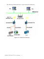
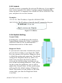
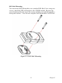
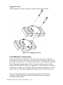
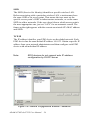
ADAM-4570W
2-Port RS-232/422/485 to WLAN
Data Gateway
ADAM-4571W
1-Port RS-232/422/485 to WLAN
Data Gateway
User Manual
Copyright
The documentation and the software included with this product are copyrighted 2005 by Advantech Co., Ltd. All rights are reserved. Advantech
Co., Ltd. reserves the right to make improvements in the products
described in this manual at any time without notice. No part of this manual may be reproduced, copied, translated or transmitted in any form or
by any means without the prior written permission of Advantech Co., Ltd.
Information provided in this manual is intended to be accurate and reliable. However, Advantech Co., Ltd. assumes no responsibility for its use,
nor for any infringements of the rights of third parties, which may result
from its use.
Acknowledgements
Intel and Pentium are trademarks of Intel Corporation.
Microsoft Windows and MS-DOS are registered trademarks of
Microsoft Corp.
All other product names or trademarks are properties of their respective
owners.
Part No.2003457000
1st Edition
Printed in Taiwan
July 2005
ADAM-4570W & 4571W User Manual
ii
Product Warranty (2 years)
Advantech warrants to you, the original purchaser, that each of its products will be free from defects in materials and workmanship for two years
from the date of purchase.
This warranty does not apply to any products which have been repaired or
altered by persons other than repair personnel authorized by Advantech,
or which have been subject to misuse, abuse, accident or improper installation. Advantech assumes no liability under the terms of this warranty as
a consequence of such events.
Because of Advantech’s high quality-control standards and rigorous testing, most of our customers never need to use our repair service. If an
Advantech product is defective, it will be repaired or replaced at no
charge during the warranty period. For out-of-warranty repairs, you will
be billed according to the cost of replacement materials, service time and
freight. Please consult your dealer for more details.
If you think you have a defective product, follow these steps:
1.
Collect all the information about the problem encountered. (For
example, CPU speed, Advantech products used, other hardware
and software used, etc.) Note anything abnormal and list any
onscreen messages you get when the problem occurs.
2.
Call your dealer and describe the problem. Please have your manual, product, and any helpful information readily available.
3.
If your product is diagnosed as defective, obtain an RMA (return
merchandize authorization) number from your dealer. This allows
us to process your return more quickly.
4.
Carefully pack the defective product, a fully-completed Repair and
Replacement Order Card and a photocopy proof of purchase date
(such as your sales receipt) in a shippable container. A product
returned without proof of the purchase date is not eligible for warranty service.
5.
Write the RMA number visibly on the outside of the package and
ship it prepaid to your dealer.
iii
CE
This product has passed the CE test for environmental specifications
when shielded cables are used for external wiring. We recommend the use
of shielded cables. This kind of cable is available from Advantech. Please
contact your local supplier for ordering information.
FCC Class B
Note: This equipment has been tested and found to comply with the limits
for a Class B digital device, pursuant to part 15 of the FCC Rules. These
limits are designed to provide reasonable protection against harmful
interference in a residential installation. This equipment generates, uses
and can radiate radio frequency energy and, if not installed and used in
accordance with the instructions, may cause harmful interference to radio
communications. However, there is no guarantee that interference will
not occur in a particular installation. If this equipment does cause harmful
interference to radio or television reception, which can be determined by
turning the equipment off and on, the user is encouraged to try to correct
the interference by one or more of the following measures:
• Reorient or relocate the receiving antenna.
• Increase the separation between the equipment and receiver.
• Connect the equipment into an outlet on a circuit different from that to
which the receiver is connected.
• Consult the dealer or an experienced radio/TV technician for help.
Technical Support and Assistance
Step 1. Visit the Advantech web site at www.advantech.com/support
where you can find the latest information about the product.
Step 2. Contact your distributor, sales representative, or Advantech's customer service center for technical support if you need additional
assistance. Please have the following information ready before
you call:
- Product name and serial number
- Description of your peripheral attachments
- Description of your software (operating system, version, application software, etc.)
- A complete description of the problem
- The exact wording of any error messages
ADAM-4570W & 4571W User Manual
iv
Contents
Chapter
1 Overview .......................................................... 2
1.1
1.2
1.3
1.4
1.5
Chapter
Introduction ....................................................................... 2
Features ............................................................................. 3
Specifications .................................................................... 3
Packing List....................................................................... 4
Ordering Information ........................................................ 4
2 Getting Started ................................................ 6
2.1
Installation Procedure Overview....................................... 6
2.2
Understanding ADAM-4570W & ADAM-4571W........... 7
Figure 2.1:Installation Flow Chart ................................. 6
2.2.1
2.2.2
2.2.3
2.2.4
2.3
Connecting the Hardware................................................ 12
2.3.1
2.3.2
2.3.3
Chapter
Network Architecture .................................................... 7
Figure 2.2:Network Architecture ................................... 8
LED Definitions ............................................................. 9
Table 2.1:LED Definitions ............................................ 9
Labels ........................................................................... 10
Figure 2.3:Sticker ......................................................... 10
Switch Setting .............................................................. 10
Table 2.2:Diagnostic Mode Default Setting ................ 11
Choosing a Location .................................................... 12
Figure 2.4:Panel Mounting .......................................... 12
Figure 2.5:DIN Rail Mounting .................................... 13
Figure 2.6:Piggyback Stack ......................................... 14
Wireless Connection .................................................... 14
Figure 2.7:Power Conn. for ADAM-4570W/4571W .. 15
Serial Connection ......................................................... 16
Table 2.3:RJ-48 to DB-9 Cable Pin Assignment ......... 16
3 Installation & Configuration........................ 18
3.1
3.2
Driver and Utility Installation ......................................... 18
Configuring EDG Series-ADAM-4570W/4571W.......... 19
3.2.1
3.2.2
3.2.3
Search for Specific EDG Devices ................................ 19
Figure 3.1:Locate All EDG Series ............................... 20
Figure 3.2:Locate Designated Group of ADAM-4570 20
Figure 3.3:Locate the Specific ADAM-4570W ........... 21
System Configuration .................................................. 22
Figure 3.4:System Configuration Window .................. 22
Network Configuration ................................................ 23
Figure 3.5:Network Configuration Window-General .. 23
Table 3.1:Channel and Freq. Corresponding Table ..... 25
Figure 3.6:Network Config. Window-“Advanced” ..... 26
Table 3.2:Adv. Parameters’ Default Value & Range .. 27
Figure 3.7:Network Config. - “Authentication” .......... 29
Table 3.3:Key Setting Index ........................................ 30
v
3.2.4
3.2.5
3.2.6
3.2.7
3.3
Figure 3.8:Network Config.Window-“Site Survey” .... 30
Port Configuration ....................................................... 31
Figure 3.9:Port Configuration Window ....................... 31
Security Configuration ................................................. 33
Figure 3.10:Security Configuration Window .............. 33
Status Messages .......................................................... 34
Figure 3.11:Status Messages ........................................ 34
Connection Diagnostic ................................................. 35
Port Mapping Utility ....................................................... 36
3.3.1
3.3.2
3.3.3
3.3.4
Figure 3.12: Unused Ports ........................................... 36
Figure 3.13:Assign COM Port to EDG Series ............. 37
Figure 3.14: Warning Window .................................... 37
Figure 3.15:Remove COM port ................................... 38
Self Test Function ........................................................ 38
Figure 3.16:Test Window ............................................ 39
Figure 3.17:Loopback Test .......................................... 40
Upgrading Firmware .................................................... 40
Figure 3.18:Firmware Update Window ....................... 41
Figure 3.19:Select the Wanted Update Firmware File 41
Figure 3.20:Download and Update Firmware ............. 42
Save the Configuration ................................................ 42
Figure 3.21:Import & Export via File Column ............ 42
Auto-Reconnection Function ....................................... 43
Figure 3.22:Auto Reconnect ........................................ 43
Chapter 4 Troubleshooting............................................. 46
Appendix A Quick Start..................................................... 50
A.1
A.2
Diagnostic Ad hoc Mode (with wireless module)........... 50
Via Diag. Infrastructure Mode (w/o wireless module) ... 53
Appendix B Compatible Access Points............................. 56
ADAM-4570W & 4571W User Manual
vi
CHAPTER
1
2
Overview
This chapter provides an overview of
ADAM-4570W and ADAM-4571W.
Sections include:
• Introduction
• Features
• Specifications
• Packing List
• Ordering Information
Chapter 1 Overview
1.1 Introduction
ADAM-4570W and ADAM-4571W are cost-effective data gateways
between RS-232/422/485 and 802.11b Wireless LAN interfaces. They
provide a quick and low-cost method to connect any RS-232/422/485
device to 802.11b wireless LAN. Functionally transparent and efficient,
ADAM-4570W and ADAM-4571W saves costs when existing hardware
and software must continue to be used. ADAM-4570W and ADAM4571W bring the advantages of remote management and data accessibility to thousands of RS-232/422/485 devices that cannot connect to the
network.
ADAM-4570W and ADAM-4571W provide one or two RS-232/422/485
serial ports, and the transmission speed is up to 230 kbps, meeting the
demand for high-speed data exchange. In addition, you can use a Windows utility to configure ADAM-4570W and ADAM-4571W without
further programming. This not only protects your current hardware
investment but also ensures future network expandability. Since the protocol conversion is transparent, all your existing devices can be seamlessly integrated with the 802.11b wireless LAN network. Therefore,
ADAM-4570W and ADAM-4571W can be used in security systems, factory automation, SCADA, transportation and more.
ADAM-4570W and ADAM-4571W integrate both your existing humanmachine interface software (HMI) and the RS-232/422/485 system architecture with an 802.11b Wireless LAN network. The result helps you
save cabling and software development costs. Another benefit is that
ADAM-4570W and ADAM-4571W makes it possible to remotely download programs to a designated device via an 802.11b wireless LAN. This
reduces the need for on-site maintenance and diagnosis. In addition,
ADAM-4570W and ADAM-4571W comes with a Windows configuration and a port-mapping utility. The configuration tool can auto-detect all
802.11b wireless LAN Data Gateway products on the local network. It
also lets you adjust all settings easily. The port mapping utility helps you
to set up COM ports for a Windows 98/NT/2000 or XP platform. This
helps you configure all ports to meet your requirements.
ADAM-4570W & 4571W User Manual
2
1.2 Features
• Supports 802.11b standard
• Supports Wireless LAN Ad-Hoc and Infrastructure modes
• Supports high transmission speeds up to 230 kbps
• Supports an advanced security mechanism to avoid unauthorized access
• Auto-reconnection
• Remote download of firmware
• Auto-detection
• Easily-managed Port Mapping Utility
• Supports Windows 98/NT/2000/XP driver
• Surge protection for RS-485 line and power supply
• Automatic RS-485 data flow control
1.3 Specifications
• Protocol: TCP/IP
• Network: 802.11b
• Ports: ADAM-4571W: 1 RS-232/422/485 port
ADAM-4570W: 2 independent RS-232/422/485 ports
• Connector: Serial: RJ-48 (RJ-48 to DB9 male cable provided)
• Transmission Speeds: 50 bps ~ 230 kbps
• Parity Bits: Odd, even, none, space, mark
• Data Bits: 5, 6, 7, 8
• Stop Bits: 1, 1.5, 2
• Diagnostic LEDs: WLAN (Active, Quality), Serial (TX/RX) and System(Status, Power)
• Surge Protection: 15 kVESD
• Utility Software:
Auto-detection configuration utility (up to 128 devices)
Port mapping utility
• Driver Support: Windows 98/NT/2000/XP
3
Chapter 1
• Power Requirement: Unregulated 10 ~ 30 VDC
• Power Consumption: Max @ 4 W
• Mounting: DIN-rail, panel mounting, piggyback stack
• Operating Temperature: 0 ~ 55° C (32 ~ 131° C)
• Storage Temperature: -20 ~ 80° C (-4 ~ 176° C)
• Operating Humidity: 20 ~ 95% (non-condensing)
• Storage Humidity: 0 ~ 95% (non-condensing)
1.4 Packing List
Before setting up the system, check that the items listed below are
included and in good condition. If any item does not accord with the
table, please contact your dealer immediately.
• CD-ROM for utility and manual
• 1m RJ-48 to male DB9 RS-232/422/485 cable (1 with ADAM-4571W,
2 with ADAM-4570W)
• One RS-232 loopback DB9 tester
• EMI Dia. 7.8mm/L82mm Wireless LAN Antenna
• Five labels
• Nylon DIN-rail Mounting Adapter
• SECC Panel Mounting Bracket
1.5 Ordering Information
• ADAM-4570W 2-port RS-232/422/485 to WLAN Data Gateway
(2pcs of 1m RJ-48 to male DB9 RS-232/422/485 cable included)
• ADAM-4571W 1-port RS-232/422/485 to WLAN Data Gateway
(1pcs of 1m RJ-48 to male DB9 RS-232/422/485 cable included)
• OPT1A 1m RJ-48 to male DB9 RS-232/422/485 cable
• OPT1D 30cm RJ-48 to male DB9 RS-232/422/485 cable
ADAM-4570W & 4571W User Manual
4
CHAPTER
2
2
Getting Started
In this chapter, you will be given an
overview of hardware installation procedure for ADAM-4570W and
ADAM-4571W. As mentioned in the
previous chapter, ADAM-4570W and
ADAM-4571W comes ready for all
network connections, including WLAN
and RS-232/422/485 port connections..
Sections include:
• Installation Procedure Overview
• Understanding ADAM-4570W &
ADAM-4571W
• Connecting the Hardware
Chapter 2 Getting Started
2.1 Installation Procedure Overview
See the flow chart below for a brief overview of the installation procedure.
Figure 2.1: Installation Flow Chart
ADAM-4570W & 4571W User Manual
6
2.2 Understanding ADAM-4570W & ADAM-4571W
ADAM-4570W and ADAM-4571W are advanced data gateway units.
They extend traditional COM ports of a PC by giving them access to an
802.11b WLAN network. Since ADAM-4570W and ADAM-4571W are
connected through an 802.11b WLAN network, you will need to know
some basic facts about networking in order to get the server hooked up
correctly.
2.2.1 Network Architecture
Traditional serial port communication uses a COM port board that slides
into one of the slots at the back of your PC. In this case, only the computer containing the board can access the
serial port. With ADAM-4570W or ADAM-4571W, you are now able to
access the COM port from a distance through a local area network and
WLAN. ADAM-4570W and ADAM-4571W can be integrated within the
network architecture of any protocol.
Note, all serial devices which are connected to the same port must have
the same protocol running, and the same transmission speed. Connect
devices with different protocols to different ports of ADAM-4570W or
ADAM-4571W.
7
Chapter 2
The following illustration shows a typical network architecture:
Figure 2.2: Network Architecture
ADAM-4570W & 4571W User Manual
8
2.2.2 LED Definitions
There are network status LEDs located on the top panel of ADAM4570W and ADAM-4571W. ADAM-4570W has five, while ADAM4571W has four. Each has its own specific function.
Table 2.1: LED Definitions
LED
Color
Status
Description
Status/
Power
Red
ON
Blinking (1 time/sec)
OFF
Not working
Green
ON
Power ON
OFF
Power OFF
Red
ON
Data being transmitted or
received
OFF
No data action
Red/Green
OFF/OFF
0 ~ 20% signal strength
Red/Green
OFF/Half-On
20 ~ 40% signal strength
Red/Green
OFF/Full-ON
40 ~ 60% signal strength
Red/Green
Half-On/FullON
60 ~ 80% signal strength
Red/Green
Full-ON/FullON
80 ~100% signal strength
Red
ON
Serial port1 data being
transmitted
OFF
Serial port1 no data being
transmitted
ON
Serial port1 data being
received
OFF
Serial port1 no data being
received
ON
Serial port2 data being
transmitted
OFF
Serial port2 no data being
transmitted
ON
Serial port2 data being
received
OFF
Serial port2 no data being
received
Active
Quality
TX/
RX(Port1)
Green
TX/
RX(Port2)
(4570W
only)
Red
Green
9
Chapter 2
2.2.3 Labels
To make it easier to remember the relevant IP addresses of your application, we have provided five labels. Use these to note information like
where the host PC is mapped to the ADAM-4570W or ADAM-4571W
port, and place it in a secure location.
Examples:
172.18.1.59: The IP address of specific ADAM-4570W.
160.59.20.89: The IP address of specific host PC mapped to this port.
Figure 2.3: Sticker
2.2.4 Switch Setting
Normal Mode
In normal use, you should move the switch to
Normal Mode, and use the Utility to configure
ADAM-4570W/4571W for different BSS --Infrastructure mode or Ad hoc mode.
Diagnostic Mode
If your network connection is broken and you forgot your device setting, or you forgot the WEP
key, you can move the switch to Diagnostic Mode
to rebuild the setting and connection. The default
setting in the Diagnostic Mode as Table 2.2 is
fixed. You can connect the host PC and the
device by the default setting, and then you can
reset all the networking parameters. After rebooting the system, the parameters you set will be
applied into Normal Mode. All the modifications
will not effect the default setting of Diagnostic
Mode. That means you can always see the same
setting while you enter the Diagnostic Mode
every time.
ADAM-4570W & 4571W User Manual
10
In the same way, there are two kinds of BSS -- infrastructure mode and ad
hoc mode -- exist in Diagnostic Mode. Table 2.2 shows how to enter the
mode you want by adjusting the switch.
Table 2.2: Diagnostic Mode Default Setting
Diagnostic Ad hoc
Mode
Diagnostic Infrastructure Mode
SSID
WLAN
ANY
Channel
10
N/A
WEP
No
No
Enter Way
1: Power Off
1: Power Off
2: Put switch at
Diagnostic Mode
2: Put switch at Normal Mode
3: Power ON and
wait for 6~10 seconds for rebooting,
then the module will
be in Diagnostic Ad
hoc mode.
Note:
3: Power ON and wait for 6~10 seconds for rebooting
(*Note: Taking the step1~3 to
ensure ADAM-4570W/4571W is in
the Normal Mode)
4: Put the switch to Diagnostic
Mode, and then wait for 5 seconds.
After 5 seconds, the signal LED will
start to flash for 5 seconds. During
the 5-second interval, you have to
put the switch back to Normal Mode,
and the module will reboot to
Diagnostic Infrastructure Mode.
(*Note: If you don’t put the switch
back to Normal Mode during the 5second, the module will reboot to
Diagnostic Ad hoc mode.)
Please refer to Appendix A "Quick Start" if
setting or resetting the wireless connection
11
Chapter 2
2.3 Connecting the Hardware
Next, we will explain how to mount your ADAM-4570W /ADAM4571W module, and then how to connect to the WLAN network, hook up
the power cable, and connect the ADAM-4570W/4571W’s serial port to
serial devices.
Note:
If you are planning to install other
communication cards, we recommend that this is
done before the ADAM module is installed.
2.3.1 Choosing a Location
There are three different ways to mount ADAM-4570W and ADAM4571W:
• Panel mounting
• DIN rail mounting
• Piggyback stacking
Panel Mounting
ADAM-4570W and ADAM-4571W can be attached to a wall or flat
surface using the included wall-mounting bracket. The bracket comes
with four screws. First attach the bracket on the bottom of the ADAM
module, and then screw the bracket to the wall or flat surface.
Figure 2.4: Panel Mounting
ADAM-4570W & 4571W User Manual
12
DIN Rail Mounting
You can mount ADAM modules on a standard DIN Rail. First, using two
screws, attach the DIN rail bracket to the ADAM module. Because the
screw heads are flat, the top of the screws will be even with the module’s
front panel surface. You can now snap the ADAM module to a DIN rail.
Figure 2.5: DIN Rail Mounting
13
Chapter 2
Piggyback Stack
ADAM modules can be stacked as shown in the figure below.
Figure 2.6: Piggyback Stack
2.3.2 Wireless Connection
ADAM-4570W and ADAM-4571W operate in the 802.11b WLAN
environment, which is created by an access point working with 802.11b
protocols. Locate your access point and connect to the Ethernet network
first. Then build up the connection between the access point and the
ADAM-4570W/4571W (Refer to Appendix A "Quick Start"). After the
connection is ready, you can follow the steps shown in chapter 3 to configure and set virtual port mapping through network and access point.
You can check the signal access quality with the “Quality” LED
indicator. Adjust the antenna of the ADAM module to optimize
communication quality.
ADAM-4570W & 4571W User Manual
14
Power Connection
You should take the following steps to connect power to the ADAM
module.
1. Connect the power cable to the 2-pin connector.
2. Connect the power cable to the power adapter.
Figure 2.7: Power Connection for ADAM-4570W/4571W
If ADAM-4570W / ADAM-4571W are working properly, the green
power LED will be lit.
15
Chapter 2
2.3.3 Serial Connection
ADAM-4570W has two, while ADAM-4571W has one RJ-48 serial port
phone jack on the bottom. You may use the supplied RJ-48 to DB9 cable
to connect your serial device. Simply plug the RJ-48 end of the cable into
the jack, and plug the DB9 end into the serial connector of the serial
device. The pin assignment of the RJ-48 to DB-9 cable is shown in the
table below.
Table 2.3: RJ-48 to DB-9 Cable Pin Assignment
RJ-48
Male DB9 (DB9-M)
1 2 3 4 5
6 7 8 9
Pin
1
2
3
4
5
6
RS-232
DCD
RX
TX
DTR
GND
RS-422
TX-
-
-
TX+
GND
RS-485
DATA-
DATA+
GND
ADAM-4570W & 4571W User Manual
16
7
8
9
DSR RTS
CTS
RI
-
RX+
-
RX-
-
-
-
-
CHAPTER
3
2
Installation &
Configuration
This chapter first guides you in the
installation of drivers and software utilities, and then shows how to use the
software utilities.
Sections include:
• Driver and Utility Installation
• Configuring EDG Series-ADAM4570W/4571W
• Port Mapping Utility
Chapter 3 Installation & Configuration
3.1 Driver and Utility Installation
In order to use a PC via an Ethernet network to control serial devices connected to ADAM-4570W or ADAM-4571W, you must first have a host
running Windows 98/NT/2000 or XP. You also need the host to have an
Ethernet card and TCP/IP protocol installed. Following are the installation instructions to set up ADAM-4570W / ADAM-4571W.
1. Insert the Advantech INET SERIES DRIVER UTILITY CD-ROM
into the CD-ROM drive (e.g. D:\) on the host PC.
2. Use Windows Explorer or the Windows Run command to execute the
Configuration Utility setup program. If your CD-ROM is D:, the path for
the setup program will be:
D:\ADAM-4570W_4571W\Utility&Driver
\EDG COMPort Configuration Utility\98_NT_2000_XP
3. The setup program will specify a default installation path, C:\Program
Files\Advantech eAutomation\ EDG COMport\Configuration Utility.
If a different destination path is necessary, just click the ‘Browse’ button
to change to another path. After you have specified the installation path,
click the ‘Next’ button. The setup program will lead you to finish the
installation.
4. After setup has copied all program files to your computer, click the
‘Finish’ button to finish the installation.
5. Use the same method to install COMPort Mapping Utility.
6. The Configuration Utility and COMPort Mapping Utility will be
placed in the shortcuts automatically, for faster execution. When you start
Configuration Utility, it will automatically locate for Advantech Ethernet
Data Gateway (EDG) devices in the host’s network.
ADAM-4570W & 4571W User Manual
18
3.2 Configuring EDG Series-ADAM-4570W/4571W
ADAM-4570W and ADAM-4571W are part of Advantech’s EDG Series.
All products in the EDG series provide easy Windows configuration
through an Ethernet or WLAN connection and the ‘Configuration Utility’
program.
‘Configuration Utility’ can automatically find all compatible devices on a
network for easier configuration of parameters for TCP/IP.
For secure administration, ‘Configuration Utility’ can also restrict the
access rights for configuration to only one specific host PC to enhance
network security. With this security function enabled, other PCs are
effectively blocked from changing any settings. ‘Configuration Utility’
consists of four functional categories: System, Network, Port, and Security which are represented on the toolbar of the configuration utility.
Note:
When you have finished the configuration of
these settings for each category, please press
the ‘ok’, ‘apply’ and ‘reset’ button in order to
make these settings effective on all EDG
devices.
3.2.1 Search for Specific EDG Devices
If you want to locate specific EDG devices, ‘Configuration Utility’ provides a “Locate” function for assistance.
You can locate all EDG devices by the following steps.
1. Select “All Devices” and click “Locate”
2. The “Status” LED on all found devices will be lit.
19
Chapter 3
Figure 3.1: Locate All EDG Series
Or select a group of ADAM-4570 with these steps.
1. Select “Designated” and then “ADAM-4570”, and last “Locate”.
2. The “Status” LED of all “ADAM-4570” on the LAN will be lit.
Figure 3.2: Locate the Designated Group of ADAM-4570
ADAM-4570W & 4571W User Manual
20
Of course, you can select just one ADAM-4570W if you like. When you
select a specific device, the LED that stands for “Status” will be lit for 8
minutes. If you select another device, the “Status” LED of the first
selected device will turn off.
Figure 3.3: Locate the Specific ADAM-4570W
21
Chapter 3
3.2.2 System Configuration
‘Configuration Utility’ can only search for EDG devices on the local network and not beyond a router or gateway. Make sure that all EDG devices
that you want to monitor reside on the same local network as the host PC.
Figure 3.4: System Configuration Window
Device Name
‘Configuration Utility’ provides default names for the devices it finds on
the network. This is to distinguish the EDG devices from each other. You
can change the default device names to better match your application.
Names have a limit of 128 characters. It is best to choose a descriptive
name you can remember.
Device Description
This field is used to record the function, application and other information
for each EDG device in more detail for easy management and maintenance. You can describe with your own words.
ADAM-4570W & 4571W User Manual
22
Firmware Version
In this field, ‘Configuration Utility’ shows the firmware version of the
EDG device. You might need to refer to the firmware version to determine what functions are available on the EDG device. In case there are
problems concerning the firmware version, please provide the version
number to our customer service.
3.2.3 Network Configuration
Figure 3.5: Network Configuration Window-General
Wireless Firmware
Here is the firmware version of the wireless module embedded in the
ADAM-4570W/4571W. The wireless module firmware might affect the
wireless connection. Write down the version number and provide to our
customer service if you have wireless connection problems.
MAC Address
The MAC address is for the local system to identify and locate each EDG
device. This MAC address is already set before delivery from the factory;
hence there is no need for further configuration.
23
Chapter 3
Region
Set the region. Each region has its default channel range. When you
choose a specific region, the optional channel range and numbers in the
below drop-down menu will be changed automatically.
• General (USA and Canada): 1~11
• Europe (except for France and Spain): 1~13
• France: 10~13
• Spain: 10~11
• Japan: 14 only
• Japan Wide: 1~14
For other regions, please choose General, or refer to table 3.1 to find an
acceptable frequency.
Mode
There are two kinds of basic service set (BSS) in this drop-down menu.
• 11b Infrastructure
For infrastructure BSS usage, you should set up the SSID of the
specific access point (AP). Or just choose “ANY” in SSID drop-down
menu to let the wireless module automatically search and connect the
appropriate AP.
• 11b Ad hoc
For point-to-point connection, specific or independent BSS usage, you
should set the same channel and the same SSID for both points.
ADAM-4570W & 4571W User Manual
24
Channel
Each region has its default channel range, which is decided by each
region’s telecommunications laws. Table 3-1 shows the corresponding
frequency of channels. If you wish to setup two networks, it is
recommended that you use channels that are not close to each other to
minimize interference.
Table 3.1: Channel and Frequency Corresponding Table
Channel
Frequency(GHz)
1
2.412
2
2.417
3
2.422
4
2.427
5
2.432
6
2.437
7
2.442
8
2.447
9
2.452
10
2.457
11
2.462
12
2.467
13
2.472
14
2.477
Data Rate
The data transmission rate is determined by the device and access point.
If there is a restriction for the device or AP, a fixed data rate has to be
chosen. Otherwise, we suggest the “Automatic” choice.
25
Chapter 3
SSID
The SSID (Service Set Identity) identifies a specific wireless LAN.
Before associating with a particular wireless LAN, a station must have
the same SSID as its access point. That means the user must set the
specific access point’s SSID in infrastructure networks, or set the same
SSID in ad hoc networks. If the user doesn’t know which access point is
the most appropriate one, just set “ANY” for an automatic search. The
frame on the right appears with the current associated AP’s MAC address
and SSID.
TCP/IP
The IP address identifies your EDG device on the global network. Each
EDG device has the same default IP address 10.0.0.1. Obtain a specific IP
address from your network administrator and then configure each EDG
device with an individual IP address.
Note:
EDG devices do not support auto IP address
configuration by DHCP server.
Figure 3.6: Network Configuration Window-“Advanced”
ADAM-4570W & 4571W User Manual
26
The “Advanced” drop-down menu identifies several parameters that are
related to the 802.11b wireless network. We suggested the default settings are not changed unless necessary.
Table 3.2: Advanced Parameters’ Default Value and Range
Parameters
Default Value
Range
Beacon Interval
100
0~65535
RTS Threshold
2347
0~2347
Fragment Threshold
2346
256~2346
Preamble
Long
Long/Short
Beacon Interval
In infrastructure networks, the access point periodically sends beacons.
You can set the beacon interval with the access point configuration
screen. In general, the beacon interval is set to 100 ms, which provides
good performance for most applications.
In ad hoc networks, there are no access points. As a result, one of the peer
stations assumes the responsibility for sending the beacon. After receiving a beacon frame, each station waits for the beacon interval and then
sends a beacon if no other station does so after a random time delay. This
ensures that at least one station will send a beacon, and the random delay
rotates the responsibility for sending beacons.
By increasing the beacon interval, you can reduce the number of beacons
and associated overhead, but that will likely delay the association and
roaming process because stations scanning for available access points
may miss the beacons. You can decrease the beacon interval, which
increases the rate of beacons. This will make the association and roaming
process very responsive; however, the network will incur additional overhead and throughput will go down. In addition, stations using power save
mode will need to consume more power because they'll need to awaken
more often, which reduces power saving mode benefits.
27
Chapter 3
RTS Threshold
RTS Threshold is the frame size above that an RTS/CTS handshake will
be performed before attempting to transmit. RTS/CTS asks for permission to transmit to reduce collisions, but adds considerable overhead. Disabling RTS/CTS can reduce overhead and latency in WLANs where all
stations are close together, but can increase collisions and degrade performance in WLANs where stations are far apart and unable to sense each
other to avoid collisions. If you are experiencing excessive collisions, you
can try turning RTS/CTS on or (if already on) reduce RTS/CTS Threshold on the affected stations.
Fragmentation Threshold
Fragmentation Threshold is the maximum length of the frame, beyond
which payload must be broken up into two or more frames. Collisions
occur more often for long frames because sending them occupies the
channel for a longer period of time, increasing the chance that another
station will transmit and cause a collision. Reducing Fragmentation
Threshold results in shorter frames that "busy" the channel for shorter
periods, reducing packet error rate and resulting retransmissions. However, shorter frames also increase overhead, degrading maximum possible throughput, so adjusting this parameter means striking a good balance
between error rate and throughput.
Preamble
A preamble is a signal used in network communications to synchronize
the transmission timing between two or more systems. Proper timing
ensures that all systems are interpreting the start of the information transfer correctly.
ADAM-4570W & 4571W User Manual
28
Figure 3.7: Network Configuration Window-“Authentication”
WEP Authentication Type
WEP (Wired Equivalent Privacy) is a kind of standard to encrypt the data
frame.
• Open system: No encryption for network communication. You can
neglect the key setting on the right side.
• WEP Share Key: Both communication devices use the same key as
encryption.
• Automatic: Detect the WEP situation of the access point automatically.
ADAM-4570W/4571W will use the current key for encryption. If
ADAM-4570W/4571W’s key does not coincide with the access point’s
key, the user should reset the same key and reboot to connect.
Encryption
If the system needs WEP encryption, the user has to set the key type.
There are two kinds of encryption keys: 64 bits and 128 bits. For an open
system, the encryption function is disabled.
29
Chapter 3
Key Index
This lists the supported encryption keys that you can choose from.
Key Format
Set the key format. Table 3.3 shows the allowed characters and length of
the different key index and key formats.
Table 3.3: Key Setting Index
Alphanumeric
Hexadecimal
64 bits
Up to 5 random characters
on the keyboard
Up to 10 random hexadecimal
characters (0 ~ 9, a ~ f)
128 bits
Up to 13 random characters
on the keyboard
Up to 26 random hexadecimal
characters (0 ~ 9, a ~ f)
Figure 3.8: Network Configuration Window-“Site Survey”
The site survey tab submenu lists information about the access points that
ADAM-4570W/4571W could find when ‘Configuration Utility’ started.
You should press the ‘Refresh’ button to update the site survey data.
ADAM-4570W & 4571W User Manual
30
3.2.4 Port Configuration
Figure 3.9: Port Configuration Window
Name
Select which port on the EDG device is to be connected to the serial
device.
Description
You can give a more detailed description on the function of the port for
easier management and maintenance. Descriptions have a limit of 128
characters.
Type
The EDG device offers three kinds of serial protocols, RS-232, RS-485
and RS-422. You can use any of the three serial protocols according to
your requirements.
Parity
The EDG device provides five options: None, Odd, Even, Space, Mark.
31
Chapter 3
Flow Control
The EDG device provides four options: None, Xon/Xoff, RTS/CTS,
DTR/DSR.
Data Bits
The EDG device provides four options: 5, 6, 7 or 8.
Stop Bits
The EDG Series provides three options: 1, 1.5 or 2.
Baud Rate
The EDG Series supports baud rates from 50 to 230,400bps.
Host Idle Timeout
With ADAM-4570W and ADAM-4571W, ‘Configuration Utility’ allows
setting of the host idle timeout value. When the system is idle for more
than the set value, the utility will cut off the connection between ADAM4570W/4571W and the host automatically. You must reconnect to
recover communications.
After setting all the above parameters, press the “Set ALL Port” button to
finish the port configuration.
ADAM-4570W & 4571W User Manual
32
3.2.5 Security Configuration
Figure 3.10: Security Configuration Window
Only configure the authorized IP
This option is enabled in order to protect all configuration settings from
being changed inadvertently.
Allow any IP to access
If this option is enabled, any PC can access data from this EDG device.
The specified IP which can access
If you want to restrict access to certain PCs, you can list their IP addresses
in this area. The limit is 32 PCs.
33
Chapter 3
3.2.6 Status Messages
The status messages shown at the bottom of the utility window reflects
the current status of the EDG device.
Figure 3.11: Status Messages
Read
The configuration utility has found the EDG device and is ready for use.
Searching EDG COM port
The configuration utility is searching for EDG devices.
Querying DATA from EDG COM port
The configuration utility is getting data from the EDG device.
Device Ready
The EDG device is ready to be configured and is now waiting for
acknowledgement from the serial device.
ADAM-4570W & 4571W User Manual
34
Lost Connection from the Device
Due to device shut down or network failure, the configuration utility has
lost connection after 5 seconds.
Fail to apply this setting to the device
Your settings are not accepted by the EDG device.
The device fails to respond
The connected device does not respond.
Fail to reset the device
Fail to reset the EDG device.
3.2.7 Connection Diagnostic
When you complete the configuration of your EDG device, you can follow the steps to check if the EDG Series connects to a network or not.
1. Start Microsoft DOS.
2. Execute “PING” command and type the IP address of your EDG
device. If the EDG device is connected to your network, it will display in
the screen with a response rate. If the EDG device cannot be pinged, you
will need to ask someone at the remote site to check and see if the power
is on, and make sure that the connection is working.
35
Chapter 3
3.3 Port Mapping Utility
The purpose of ‘Port Mapping Utility’ is to help you manage all serial
ports that are in one Windows-based PC. The utility displays three types
of ports: Used ports, Unused ports and EDG device ports. Please follow
the steps below.
1. Click the “Unused Ports” item and select the port that you want to configure.
Figure 3.12: Unused Ports
ADAM-4570W & 4571W User Manual
36
2. Click the “Add” button to assign a COM port to a specific EDG device.
Figure 3.13: Assign COM Port to EDG Series
3. Type the IP address of the EDG device and select ports.
Figure 3.14: Warning Window
Note:
You can not assign two virtual COM ports to
the same EDG port. If this happens, a dialog
box will appear to warn you.
4. The port has been added to the EDG device
37
Chapter 3
5. If you want to remove the COM port connection, click “Delete” to
remove it.
Figure 3.15: Remove COM port
6. After you complete the configuration, click ”Apply” .
3.3.1 Self Test Function
The purpose of this test is to make sure the communication from host PC
to ADAM-4570W/4571W is OK. If there is still an error, you can check
the communication from the ADAM-4570W/4571W to the serial devices.
If the test is selected, an external test will be done to check that the connection signals for each port are working properly. For the test, you will
need to connect each port to a loopback tester (provided in the package).
The loopback test only applies to RS-232 mode. The test is divided into
two parts: Signal test and Communication Parameters test.
ADAM-4570W & 4571W User Manual
38
1. Click the Test button in ‘Port Mapping Utility’.
Figure 3.16: Test Window
Signal Test
• RTS -> CTS Check the RTS and CTS signals between two ports
• DTR -> RI Check the DTR and RI signal between two ports
• DTR -> DSR Check the DTR and DSR signal between two ports
• DTR -> DCD Check the DTR and DCD signal between two ports
Communication Parameters Test
• Baud rate 50 bps ~ 230.4 kbps
• Data bit
5, 6, 7, 8
• Stop bit
1, 1.5, 2
• Parity
Odd, Even, None, Space, Mark
39
Chapter 3
1.Click the OK button to return to the port mapping window. All the
ports in the EDG Series are tested ok.
Figure 3.17: Loopback Test
3.3.2 Upgrading Firmware
Advantech continually upgrades its firmware to keep up with the everexpanding world of computing. You can use the download function
located in ‘Port Mapping Utility’ to carry out the upgrade procedure.
Please access Advantech’s Web site at http://www.advantech.com to
download the latest version of the firmware.
ADAM-4570W & 4571W User Manual
40
1. Click on the Update FW button.
Figure 3.18: Firmware Update Window
2. Select the firmware you want to update.
Figure 3.19: Select the Wanted Update Firmware File
41
Chapter 3
3. After downloading the firmware completely, click on the Reboot
button. The EDG device will restart automatically.
Figure 3.20: Download and Update Firmware
Note:
After clicking the Reboot button, the configuration
utility will not reboot the EDG device before all
applications stop accessing the EDG device.
3.3.3 Save the Configuration
You can save or recover the configuration via the File menu.
Figure 3.21: Import & Export via File Column
ADAM-4570W & 4571W User Manual
42
3.3.4 Auto-Reconnection Function
Sometimes, the system may crash because the EDG device is interrupted
or powered-off by accident. You would want the host PC to reconnect to
the EDG device automatically after such an occurrence. The EDG device
provides an “Auto-reconnect” function to solve this problem. If the EDG
device is powered-off accidentally, the driver will keep trying to reconnect the EDG Series automatically. When the EDG device recovers or is
powered-on, due to this auto-reconnect function, the host PC’s commands will be received by the EDG device again. This function enhances
the reliability of the system.
Figure 3.22: Auto Reconnect
Warning:
If you want to enable the “Auto-reconnect” function, please note that you can NOT enable the
“Host idle” function at the same time. The same
also applies in reverse, e.g. if you want to enable
the “Host idle” function, you also can NOT enable
the“Auto-reconnect” function at the same time.
43
Chapter 3
ADAM-4570W & 4571W User Manual
44
CHAPTER
4
2
Troubleshooting
This chapter explains how to solve
some of the most common problems
you could encounter while using
ADAM-4570W or ADAM-4571W. If
you are still having problems after
reading this chapter, contact your
dealer, or e-mail Advantech support for
help.
Chapter 4 Troubleshooting
Configuration Utility can not find ADAM-4570W/4571W
1.
Check POWER LED. If it is off, you have to check the following:
• Make sure the EDG device’s power cable is plugged in, and the server
is receiving power.
• Check that the server’s network connector is plugged in properly.
• Make sure your computer is properly connected to the network.
• Make sure the input voltage is between +10 and +30 V
2.
Check LINK LED. If it is off, check the following:
• Check if the network connection is OK.
• Make sure your network is 10 or 100 Mbps.
3.
Next, check to see if the ADAM-4570W/4571W and the host are
on the same local area network.
4.
If the steps above are all complete, it should mean that ADAM4570W/4571W can be found.
Configuration utility can find ADAM-4570W/4571W, but cannot
access ADAM-4570W/4571W
For security reasons, and to simplify operations, you can give access
rights to specific PCs. Only these PCs can get data from ADAM-4570W/
4571W. Thus, this error message will be given if trying to access ADAM4570W/4571W with a PC without access rights. Check that your PC is on
the access rights list.
Cannot change the IP address or other server properties
The network administrator is the only authorized user that can modify the
ADAM-4570W/4571W’s configuration. Keep in mind, even when multiple hosts share the same network, administrative access is still protected.
If you need to change any configuration settings, ask your network
administrator for assistance.
ADAM-4570W & 4571W User Manual
46
The host PC can access the EDG device at a local site, but after
moving the EDG device to a remote site, the PC can no longer access
it.
Due to differing network interface connections, your dynamic IP address
might have changed, and as a result, you are no longer on the ADAM4570W/4571W’s access control list.
To resolve this issue:
1.
Confirm the new IP address of the EDG device.
2.
Ask the network administrator to set up the server configuration so
that you are on the ADAM-4570W/4571W’s access control list.
Data transmission rates are very low, and the wireless connection is
sometimes broken
There are two conditions that may cause this problem:
1.
There is not enough bandwidth available. This may be caused by
too many clients, and/or transfer of large amounts of data by other
clients over the same access point.
2.
Serious signal disturbance.
Condition 1: Lack of Bandwidth
To improve transmission rates you can add more access points in the
same ESS (Extended Service Set). To do this, ensure that the same SSID
is set on each access point, but use different channels to avoid interference. Multiple access points will disperse data transmissions and solve
the traffic situation effectively.
Condition 2: Serious Signal Disturbance
You can usually solve this problem by adjusting the antenna angle, or by
covering nearby motors or generators to shield off EMI and other noise
disturbances.
47
Chapter 4
ADAM-4570W & 4571W User Manual
48
APPENDIX
A
2
Quick Start
Appendix A Quick Start
There are two ways to complete the wireless connection between an
access point and ADAM-4570W/4571W; via Diagnostic Ad hoc Mode or
via Diagnostic Infrastructure Mode. We recommend you use Ad Hoc if
your host PC is equipped with a wireless module.
A.1 Diagnostic Ad hoc Mode (with wireless module)
1.
Set the switch of ADAM-4570W/4571W to Diagnostic Mode,
then power on.
2.
Wait for 10 to 20 seconds until the signal quality is stable.
3.
Start the wireless module on your host PC (Only the WLAN is
active now, ensure the Ethernet link is inactive), scan the existing
wireless BSS (Basic Service Set) on your site.
4.
Find the BSS named WLAN
ADAM-4570W & 4571W User Manual
50
5.
Connect to WLAN BSS, and check the configuration information
to make sure the connection is O.K.
6.
Start the Configuration Utility tool on your host PC, and find the
ADAM-4570W/4571W. You can see the default setting below.
51
Appendix A
7.
Reset the Network setting as needed. (About Network setting,
please refer to section 3.2.3 of the manual)
Power off ADAM-4570W/4571W, adjust the switch to Normal Mode,
then reboot it to finish the wireless connection. Now you can configure
and set up port mapping through the access point (You can connect to the
access point by WLAN or Ethernet).
ADAM-4570W & 4571W User Manual
52
A.2 Via Diagnostic Infrastructure Mode (without
wireless module)
1.
Set the switch of ADAM-4570W/4571W to Normal Mode, then
power on.
2.
Wait for 10 to 20 seconds until the signal quality is stable.
3.
Adjust the switch to Diagnostic Mode, then wait for 5 seconds
until the signal quality is blinking.
4.
Return the switch to Normal Mode , then ADAM-4570W/4571W
will reboot automatically with Diagnostic Infrastructure Mode.
Now ADAM-4570W/4571W will automatically search the field
site for access points and create a connection to the one with best
signal quality.
5.
Start the Configuration Utility tool on your host PC (ensure your
host PC and the possible access points that ADAM-4570W/4571W
can connect to, are in the same network). Find the ADAM-4570W/
4571W on the network.
6.
Reset the network setting as required. (About Network settings,
please refer to section 3.2.3 of the manual)
7.
Power off ADAM-4570W/4571W, confirm the switch is on Normal Mode, then reboot it to finish the wireless connection. Now
you can configure and set up port mapping through an access point
(You can connect to the access point by WLAN or Ethernet).
53
Appendix A
ADAM-4570W & 4571W User Manual
54
B
APPENDIX
2
Compatible Access
Points
Appendix B Compatible Access Points
The table below shows compatible access points for ADAM wireless
products.
Item
Brand
Model
Standard
1
CISCO
Aironet 1100 series
AIR-AP1T21G-A
802.11b/g
2
3COM
3CRTRV10075/WL-534
802.11b/g
3
D-Link
DI-514
802.11b
4
ASUS
WL-330G
802.11b/g
5
ZCOM
XI-1450
802.11b
ADAM-4570W & 4571W User Manual
56