1
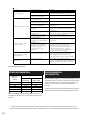
OPERATIONAL SUMMARY
Maximum mains pressure
Operating pressure
Expansion vessel charge pressure
Expansion relief valve setting
T&P relief valve setting
Maximum primary circuit pressure
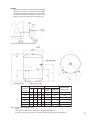
Storage capacity
Weight when full
16 bar
3.5 bar
3.5 bar
6 bar
90°C/10 bar
3 bar
See Table1
See Table1
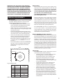
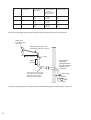
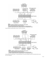
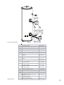
Fig. 2: Cold water combination valve assembly
INSTALLATION – GENERAL
(SEE FIGS. 2 - 6)
PIPE FITTINGS
All pipe fittings are made via 22mm compression
fittings directly to the unit. The fittings are threaded
3/4”BSP male parallel should threaded pipe connections be required.
COLD FEED
A 22mm cold water supply is recommended, however,
if a 15mm (1/2”) supply exists, which provides sufficient
flow, this may be used (although more flow noise
may be experienced).
A stopcock or servicing valve should be incorporated
into the cold water supply to enable the CENTERSTORE
cylinder and its associated controls to be isolated
and serviced.
COLD WATER COMBINATION VALVE ASSEMBLY (FIG.
2)
The 2-piece cold water combination valve assembly
can be located anywhere on the cold water mains
supply prior to the expansion vessel (see Fig. 6) but
the two pieces do not have to be installed together.
The pressure reducing valve incorporates the pressure
reducer & strainer and the expansion valve incorporates
the expansion & check valves. Ensure that the valves
are installed in the correct order and orientation. No
other valves should be placed between the expansion valve and the CENTERSTORE cylinder.
A connection can be made between the expansion
and pressure reducing valves to provide a balanced
cold water connection. The expansion valve connection must not be used for any other purpose.
4
DRAIN TAP
A suitable draining tap should be installed in the
cold water supply to the CENTERSTORE cylinder
between the expansion valve (see Fig. 6) and the
heater at as low a level as possible.
It is recommended that the outlet point of the drain
pipework be at least 1 metre below the level of the
heater (this can be achieved by attaching a hose to
the drain tap outlet spigot).
EXPANSION VESSEL
The expansion vessel accommodates expansion
that results from heating the water inside the unit.
The expansion vessel is pre-charged at 3.5 bar. The
expansion vessel must be connected between the
expansion valve (see Fig. 2) and the CENTERSTORE
cylinder (see Fig. 6). The location of the expansion
vessel should allow access to recharge the pressure as and when necessary, this can be done using
a normal car foot pump. It is recommended that
the expansion vessel is adequately supported. An
expansion vessel wall mounting bracket is supplied
for this purpose and should be fitted.
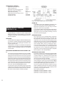
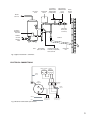
SECONDARY CIRCULATION
If secondary circulation is required it is recommended
that it be connected to the CENTERSTORE cylinder
as shown in Fig. 3 via a swept tee joint into the cold
feed to the unit. A swept tee joint is available as an
accessory (order code no. 5133565).
The secondary return pipe should be in 15mm pipe
and incorporate a check valve to prevent backflow.
A suitable WRAS approved bronze circulation pump
will be required. On large systems, due to the
increase in system water content, it may be necessary
to fit an additional expansion vessel to the secondary
circuit. This should be done if the capacity of the
secondary circuit exceeds 10 litres.
Pipe capacity (copper):
15mm O.D. = 0.13 l/m (10 litres = 77m)
22mm O.D. = 0.38 l/m (10 litres = 26m)
28mm O.D. = 0.55 l/m (10 litres = 18m)