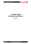
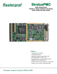
1
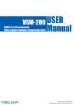
AgatePXC Rastergraf Dual Channel Graphics Controller for PMC and XMC with USB 3.0, Multichannel Video and Audio Digitizer, and Front and Rear I/O Support for VxWorks Linux Windows Features Dual channel AMD E4690 2D/3D graphics controller Dual host port interface: PMC (PCI-X) or XMC (x8 PCIe 2.0) Display resolution up to 2560x1600 512MB GDDR3 Graphics Memory On-chip x86 BIOS support Support for OpenGL 3.0 in Hardware Dual DisplayPorts on Mini DisplayPort (mDP) connectors Front panel display-only VGA, DisplayPort, or LVDS versions Rear (Pn4/Pn6) Connector Access including PIM support USB 2.0/3.0 (High & Super Speed) host controller Digitizes up to 8 each NTSC/PAL and audio simultaneously Single high-resolution RGBHV, DVI, or YUV input Single Multi-mode Analog Graphics output on I/O connector Front panel MIPI CSI-2 4-lane port On-board CPU provides comprehensive BIST support Extensive I2C, ADC, and JTAG-based diagnostics Thermal sensors monitor E4690 and board temperatures VxWorks, Linux, and Windows XP/7/8 Rastergraf - graphics and PMC carriers for embedded systems Figure 1: AgatePXC Block Diagram Conexant CX25858 Audio/Video Decoder 8X NTSC/PAL + 2 Stereo Pairs x1 x4 I2C Bus JTAG Loop STM32F427 System Management CPU STM debugger port Power Supplies LEDs Hi Res DVI Input (Rear Only) OR Hi Res RGBHV Input ADV7441A + FX3 RGBHV/DVI Input Controller uPD720201 4 Port USB 3.0 Controller x1 2.0 IDT 24T6G2 PCIe 2.0 Switch Rear only CX3 MIPI CSI-2 Camera Controller 1-4 lanes Front only x2 OR x2 AMD E4690 Graphics Processor w/512MB Memory 2.0 x4 or x8 x4 Pericom PI7C9X130 PCIe to PCI-X Bridge page 2 PMC (64/66) PCI-X Hi Res XMC PCIe 2.0 x4 or x8 FX3/CX3 UARTs AgatePXC Overview The AgatePXC fulfills high performance requirements for a complete graphics and video acquisition solution found in VxWorks, Linux, and Windows embedded systems. It can be used in an XMC, PMC, or XMC/PMC footprint and can operate in XMC locations with VPWR set to 5V or 12V. In a dual-bus footprint, it defaults to XMC. The AgatePXC uses the AMD Radeon™ E4690 Embedded Graphics Processor, which includes 320 shader processors, a 128-bit memory interface, and 512MB of GDDR3 on-chip memory. The E4690 provides hardware support for OpenGL 3.0 and DirectX 10.1 as well as video codecs. Multiple HD video streams can be decoded at once. The E4690 multi-mode analog graphics Ch 2 output supports NTSC or PAL (composite or Y/C component), RS170, 1080p HD, VGA, RGB with or without Sync on Green, and STANAG 3350 Class A-C. A front panel Honda SDR50 0.8mm connector provides the multi-mode graphics output, a MIPI CSI-2 port (4 lanes, 3.3V, I2C), 2 stereo audio inputs, 8 NTSC/PAL inputs, and a single RGBHV input. Most I/O functions are also available on a combination of the XMC Pn6 and PMC Pn4 connectors. See Table 1 for a a summary of function availability. A “Personality Interface Module” (PIM) and a dual-purpose camera adapter boardlet are also available to ease connectivity to the Agate (see pages 8-9). An ST Micro STM32F427 32-bit CPU provides Built-In Self Test (BIST) and monitoring of most AgatePXC functions using I2C, UART, JTAG, and on-chip A/D converters for voltage measurements. Reporting is done via LEDs and USB. Embedded Life-Cycle Support Screen resolutions of up to 2560x1600 are available with the AgatePXC/2 standard dual DisplayPort 1.1a outputs which use front panel Mini DisplayPort (mDP) connectors. External in-line “dongles” can transparently convert the mDP to DVI, VGA, NTSC/PAL, or a full-size DP connector. Rastergraf’s support philosophy recognizes the lead-in and life-cycle requirements expected by the embedded computing market. Please contact Rastergraf for more information or consult our web page at www.rastergraf.com. Depopulated single purpose boards include VGA-only, DisplayPort-only, and LVDS-only models. IEEE 1386-2001 32/64 Bit, 33/66/133 MHz PCI/PCI-X PMC Bus with Pn4 Rear I/O Figure 2: AgatePXC Feature Locations 4-phase quad DC-DC converter power supply (0.9V, 1.0V, 1.1V & 1.8V) VITA 46.2 XMC (PCIe 2.0 x8) with Pn6 Rear I/O Analog Devices ADV7441A RGB/DVI Digitizer and Cypress FX3 USB 3.0 controller USB/Programming Connector for STM32 PMC/XMC Power Sequencer and Temperature Manager Pericom PI7C9X130 32/64-bit, 33/66MHz PCI/PCIe Bridge YUV digital camera port AMD E4690 Dual Channel Graphics Accelerator w/512MB IDT 89HPES24T6G2 PCIe 2.0 Switch Conexant CX25858 8-Channel Audio/Video Digitizer Renesas uPD720201 4-port USB 3.0 Host Controller BIOS EEPROM ST STM32F427 32-bit CPU w/ USB, I2C, UART, and JTAG 2x Mini DisplayPort Connectors Control DIP Switch Pack for PIC CPU and E4690 2x VGA or single LVDS available in place of mDP and SDR50 0.8mm SDR50 I/O Connector Configuration DIP Switch Packs Top View Bottom View page 3 MIPI CSI-2 4-lane camera port using Cypress CX3 USB 3.0 controller AgatePXC Versions The AgatePXC/1x versions are display-only. The AgatePXC/2 includes the full feature set of the product line.The next page provides details about the display capabilities of each model. AgatePXC/1V: Dual VGA Analog Outputs The AgatePXC/1V provides two front panel VGA connectors. Each channel supports interlaced or non-interlaced RGBHV or RGB with composite or Sync-On-Green. Ch B Ch A Rastergraf AgatePXC/1D: Dual DisplayPort Digital Outputs The AgatePXC/1D provides two front panel 4-lane DisplayPort outputs using Mini DisplayPort (mDP) connectors. CX ST VOK Ch B Rastergraf Err Ch A AgatePXC/1L: Single LVDS Digital Output The AgatePXC/1L provides a front panel LVDS connector using a Honda SDR26 connector with pinout that is Mini Camera Link compatible. The output can be set up for graphics channel A or B, single or dual link, and 18 or 24 bpp pixel. Rastergraf AgatePXC/1R: Single VGA Output The AgatePXC/1R is a special purpose version that supplies a Rastergraf RG-101 compatible VGA output on the PMC Pn4 rear I/O connector. Rastergraf AgatePXC/2: Analog and/or Digital Outputs plus I/O The AgatePXC/2 front panel provides 2 Mini DisplayPort (mDP) connectors. It can also supply VGA Ch A and Ch B on the PMC Pn4 rear I/O connector. CX ST VOK Ch B It also has a front panel Honda SDR50 I/O connector that includes a multi-mode analog graphics output and a variety of audio and video inputs as described on page 6. Rastergraf Err Ch A Table 1: Connectivity for the AgatePXC Models Agate Version Multi-mode XMC Display Cable(s) VGA 8 Ch Analog and/ Port RGBHV Graphics NTSC/PAL available from Out or Out In Out Rastergraf Ch A In PMC Ch A/B (VGA Ch B) AgatePXC/1V PMC* no AgatePXC/1D PMC* no AgatePXC/1L PMC* no AgatePXC/1R PMC* AgatePXC/2 both VGA A YUV In (no DVI or RGBHV In) Audio In (stereo) USB MIPI 2.0/3.0 LVDS CSI-2 host Input port VGA B mDP-A/B SDR26 PMC Pn4 RG101 no I/O Cable PIM Adapter DVI In mDP-A/B XMC Pn6 PMC Pn4 SDR50 PMC Pn4 SDR50 PMC Pn4 XMC Pn6 SDR50 PMC Pn4 PMC Pn4 XMC Pn6 XMC Pn6 FPC 2 sets SDR50 1 set PMC Pn4 or XMC Pn6 n/a SDR50 XMC Pn6 * XMC version available by special order page 4 Graphics Display Capabilities Table 2, below, provides the details about each possible graphics output from the E4690. Power drawn on each DP or VGA port should not exceed 50mA (500mA peak). If more power is required, please use an external supply such as the Mouser 418-TR25D01. Note that regardless of the number of graphics connections on the front and/or rear panels, the E4690 itself allows only 2 channels to be active at one time. Optional external in-line dongles can convert the Mini DisplayPort output(s) to NTSC/PAL, DVI, VGA or LVDS. A passive cable can convert the Mini DisplayPort to the larger DisplayPort connector. Available cables and dongles are listed on page 15. Figure 3: E4690 Graphics Output Section Display 1 Icon & Cursor Image Display 1 Source Graphic Image 30 bpp 30 bpp Mix 30 bpp Gamma Correction Color Conversion & Correction VGA DAC1 dither Scale, Deflicker, Output Timing & Position 30 bpp VGA DAC2 Single-link DVI, HDMI , TMDSA/DPA DisplayPort 30 bpp Display 1 Source Overlay Image Output Crossbar Display 2 Source Overlay Image Dual- link DVI 30 bpp TMDSB/DPB Single-link DVI, HDMI , DisplayPort 30 bpp Single-link DVI, HDMI , TMDSC/DPC DisplayPort Dual-link DVI 30 bpp TMDSD/DPD Display 2 Source Graphic Image 30 bpp 30 bpp Mix dither Gamma Correction Color Conversion & Correction Scale, Deflicker, Output Timing & Position Single-link DVI, HDMI , DisplayPort 30 bpp LVDS / DPE or LVDS / DPF 30 bpp DVO Display 2 Icon & Cursor Image Single- or Dual-link LVDS, DisplayPort 12-bit DDR, 24-bit SDR, 24-bit DDR Table 2: AgatePXC Graphics Output Modes Video Mode Resolution Colors Channel Availability Comments Digital DisplayPort up to 2560x1600 up to 30 bpp A, B AgatePXC/2, /1D up to 4 lanes, DP 1.1a Analog Output up to 1920x1200 interlaced or non-interlaced up to 24 bpp A, B AgatePXC/2, /1V VGA, sync-on-green option RS-170 (640x480) up to 24 bpp B AgatePXC/2, /1V Composite PAL (768x575) up to 24 bpp B AgatePXC/2, /1V Composite or S-Video (Y/C) NTSC (640x480) up to 24 bpp B AgatePXC/2, /1V Composite or S-Video (Y/C) Analog HD up to 1080p up to 24 bpp A, B AgatePXC/2, /1V component YPbPr Analog NonInterlaced up to 1920x1200 up to 24 bpp A AgatePXC/1R RG-101 compatible, one output STANAG 3350 Class A-C up to 875 lines up to 24 bpp B AgatePXC/2 (contact Rastergraf for avail.) Digital LVDS up to 2048x1536 18 or 24 bpp A, B AgatePXC/1L single or dual link Analog Interlaced page 5 Audio and Video Input Capabilities Hardware Notes As shown in Table 3, below, the AgatePXC/2 provides six different input functions. Of those six, you can use only one out of DVI, RGBHV, or YUV at a given time because they share the same data path. By default, 2 stereo pairs are provided on the SDR50 connector. By special order, an additional 2 pairs can be had in place of the multi-mode analog output. Since the CX25858, FX3, and CX3 can run simultaneously, you MUST have at least a 64/66 PCI/PMC or x4 PCIe host to attain optimal performance levels. The CX2585 won’t even run on 32/33 PCI. Please see Software Support (page 11) for information about the FX3 and CX3 support. Software Notes Table 3: AgatePXC Video Input Modes Video Mode Capture Controller NTSC and/or PAL CX25858 RGBHV or DVI 7441A/FX3 YUV Digital Input MIPI CSI-2 Example Camera Typical Resolution Capture Rate (typ) Capture Mode Front/Rear Accessibility Notes 640x480 NTSC 768x576 PAL 30 NTSC 25 PAL 16-bit YUV both CX25858 can support a total of 8 NTSC and/or PAL cameras PC 1600x1200 RGBHV 1920x1200 DVI 30 16-bit YUV Both for RGBHV Rear for DVI FX3 uses 7441A for RGBHV or DVI. YUV mode bypasses 7441A. FX3 OV5640Y TBD TBD 8-bit YUV midboard edge (see above) CX3 OV5640M 2592x1944 15 16-bit YUV front Multichannel Audio/Video Digitizer The Conexant CX25858 8-input Audio/8-input Video Digitizer is PCIe-based and supports simultaneous digitizing of up to 8 each audio and NTSC/PAL video inputs. The CX25858 contains 8 high quality video decoders with 10-bit A/ADCs and 5-line comb filtering. Front and/or Rear Panel Camera Inputs Video Decoder NTSC/PAL 8X PLL As normally configured on the AgatePXC/2, 2 stereo pairs and 8 video inputs are available on the front panel. Each video input can be independently scaled and includes per-channel programmable motion detection. Front and/or Rear Panel Audio Inputs Broadband Audio ADCs 8X Mono (4X Stereo) DMA Controller 8X Video and 8X Audio Channels PCI Express TL/DLL MAC x1 PCIe 1.1 PHY Interface Agate IDT24T6 PCIe Port Motion Detection 8X I2C Controller MIPI CSI-2 2 Input Port A high performance USB 3.0-based Cypress CX3 peripheral controller supports a MIPI CSI-2 camera port with up to 4 input lanes. Access is limited to the front panel. Front Panel MIPI CSI-2 Camera An adapter boardlet (page 9) enables easy connection to an Avnet WandCam OV5640 high-resolution camera and the Agate 50-pin I/O breakout cable via a 33-pin 0.5mm FPC connector. Agate uPD720201 USB Port High Speed RGBHV or DVI Digitizer An Analog Devices ADV7441A High Speed RGB/DVI Digitizer is linked to a Cypress FX3 Cypress FX3 USB 3.0 peripheral controller. ADV7441A RGBHV/DVI Digitizer The RGBHV can be accessed at both the front and rear panel. The DVI is only available at the rear panel. The 8-bit portion of the FX3 YUV port can be accessed directly, bypassing the ADV7441A. This can be used to enable connection to an OV5640 high-resolution camera. An adapter boardlet (page 9) enables easy connection to the Agate via a 24-pin 0.5mm FPC connector. page 6 YUV Digital Camera Bypass Agate uPD720201 USB Port USB 2.0/3.0 Host Controller Host Wiring The AgatePXC/2 uses the quad-port Renesas uPD720201 USB Host Controller which is USB 3.0 (SuperSpeed), 2.0 (High Speed), and 1.1 (Full Speed) compatible. USB 2.0 supports data rates up to 480 Mbit/s and USB 3.0 up to 5Gbit/s. USB 3.0 is especially suited for even the highest resolution video and data storage applications. Please see Software Support (page 11) for information about the uPD720201, FX3 and CX3 software requirements. You will obtain best results if your host board complies with VITA 46.9 as well. If it doesn’t, it is likely that the USB port will not be reliable at USB 3.0 speeds. USB 3.0 Cables Channel 1 USB channel 1 is connected to the STM32F427 BIST Subsystem CPU HS USB port. It is used by the BIST software to communicate with the XMC or PMC host CPU. Channel 2 Note that unlike USB 2.0, it is pretty easy to build a USB 3.0 cable that doesn’t work. Cabling requires very careful length matching shielded twisted pairs for the USB 3.0 Rx and Tx pairs. If at all possible, it would be best to use commercially built cables known to comply with the USB 3.0 SuperSpeed specifications. Port Power USB channel 2 is connected to the Cypress CX3 MIPI CSI-2 USB 3.0 peripheral controller. The MIPI connections are made on the SDR50 connector on the front panel. Channel 3 USB channel 3 is available on the rear I/O (XMC Pn6) connector of the AgatePXC/2 as a standard USB 3.0 port. It supports both USB 2.0 and 3.0 modes. Note that USB Charger port operation is NOT supported. Channel 4 To help ensure that the USB 3.0 will work reliably over the host CPU or XMC carrier board, the Agate USB XMC wiring is length-matched and the pinouts follow differential data pair assignments as outlined in VITA 46.9 +X8d. USB 3.0 specifies that 0.9A @5V be supplied. However, due to the overall power requirements of the board, the Agate is not able to deliver this much current. The Agate uses a TPS2051B USB power controller, which has a design rating of 0.5A. As a practical matter, that can be exceeded, at least for a short time, depending on the operating temperature of the chip. But, if you know you are going to require on average more than 0.5A, please consider using an external supply such as the Mouser 418-TR25D-01. Channel 4 is connected to the FX3 peripheral controller which is in turn linked to the ADV7441A RGB/DVI Graphics Digitizer. Figure 4: uPD720201 Block Diagram Port 1 STM32F427 Port 2 CX3 Agate IDT24T6 PCIe 2.0 Port Port 3 Rear I/O Port 4 FX3 page 7 PIM Adapter Figure 5: PIM Block Diagram When you use both the XMC Pn6 and PMC Pn4 connectors on the Agate PIM, all of the Agate rear I/O is accessible via a connectors mounted on both sides of the PIM, as shown in the diagrams below. x4 An alternate version includes a VME P2-style connector which allows the PIM to be used with Rastergraf and Technobox PMC and XMC carriers. Hi Res RGBHV Input Camera Adapters x2 Part of the PIM is a snap-out mini-board, or boardlet, that can be used to ease the connection of cameras to the Agate. It is described in more detail on the following page. Most small cameras (see next page) connect to the controller with a 0.5mm FPC cable. There is not a lot of standardization so usually you have to make your own adapters. Hi Res DVI Input The PIM camera adapter boardlet is double-sided: a) Side 1 is for use with the Avnet WandCam MIPI CSI-2 camera. b) Side 2 is for use with OmniVision OV5640Y YUV parallel data camera. Agate PIM Figure 6: PIM Connectors Side 1&2 Snap-out Camera adapter boardlet Side 1 DisplayPort Channel A Side 2 USB 3.0 uPD720201 Port 3 XMC Pn6 I/O Connector PMC Pn4 I/O Connector Agate I/O Connector Side 2 Optional VME P2 connector for Carriers Side 1 Pn6 XMC Connector Provides 2x DisplayPort out, RGBHV or DVI in, 8x NTSC/PAL in, 1 stereo audio in, 1 USB 3.0 port Side 1 Agate SDR50 multipurpose I/O connector provides DBVI Input Ch B VGA, RGBHV in or Ch A VGA, 8x NTSC/PAL in, 1x stereo audio in or Ch B VGA DDC Side 1 Pn4 PMC Connector Provides 2x VGA out, RGBHV or DVI in, 8x NTSC/PAL in, 1x stereo audio in special order: RG-101 mode on Ch B VGA Side 1 DisplayPort Channel B page 8 Optional VME P2 Connector As of Agate Revision 2.0, a “Personality Interface Module” (PIM) is available that is VITA 36d0_1 compatible. It can be used with VME, cPCI, and OpenVPX PIM Carriers. It includes the XMC XIM enhancement suggested by Extreme Engineering which enables additional I/O to be supported. Adapter Boardlet Side 1: WandCam Figure 7: Avnet WandCam Front and Back Views Side 1 of the snap-out boardlet contains an adapter that supports the connection of an Avnet WandCam OV5640 MIPI CSI-2 camera to the Agate I/O Breakout Cable. Any MIPI CSI-2 one to four lane camera that is compatible with the WandCam standard can be supported. Referring to the diagram below, the FPC (left hand) connector is linked to the WandCam via a short length of 0.5mm pitch FPC cable. The right hand connector links to the Agate cable. This is actually a Mini DisplayPort connector, which we use because it is a perfect signal match for MIPI CSI-2, for which there is no standard connector. Figure 8: WandCam Adapter Boardlet connector to Agate I/O cable connector to Avnet WandCam MIPI CSI-2 camera Adapter Boardlet Side 2: YUV Digital Camera Side 2 of the snap-out boardlet contains an adapter that supports the connection of an 8-bit high resolution OV5640Y to an 24-pin FPC connector located mid-board on the Agate. Referring to the diagram below, the FPC (left hand) connector is linked to the camera via a short length of 0.5mm pitch FPC cable. The right hand connector links to the Agate. The Agate connector supplies 3.3V to the boardlet. Regulators on the boardlet derive 2.8 and 1.5V for the camera and apply them to the YUV camera connector Figure 9: YUV Adapter Boardlet connector to Agate FPC socket connector to YUV camera page 9 Systems Management There are a number of subsystems on the AgatePXC that are required to enable its correct and reliable operation. The startup of the power systems is set in motion by the leading edge of the system reset pulse. All host power must be stable at that time in order to ensure the proper operation of the board. Power Supply Subsystem Built-IIn Self-T Test (BIST) Controller By the very definition of a high-performance graphics board, the Agate is NOT a low-power design. For it to meet its full design specification, the calculated power requirements are: Host Bus Voltage Input PMC/XMC 3.3V 0.9A 2A PMC 5V 2.45A 6.85A An ST Micro STM32F427 CPU is used to provide Built-In Self-Test (BIST) and real-time monitoring of many AgatePXC functions using a combination of I2C, JTAG, and A to D converters (ADC) for voltage measurements. The STM firmware includes support for boot-time register setup, device testing, and even CPLD reprogramming. The STM is connected to one of the uPD720201 USB ports so that it can be controlled by the host system. XMC VPWR=5V 2.45A 6.85A Error Reporting VPWR=12V 1.1A 3A Idle Full Operation The simplest way that problems are reported is by LEDs: At the leading edge of system reset, logic selects PMC or XMC as the power source (XMC is default). Because it can deliver the most power, 5V is the power rail for the 4phase quad DC-DC converter supply. When XMC VPWR=12V, a local DC-DC converter is enabled to downconvert it to 5V. There is small efficiency cost to doing this but it simplifies the overall design. An OVP shuts down the entire power section if local 5V exceeds 5.6V. On the front panel are: Temperature Monitoring Subsystem On Side 2, along the board edge, An LM63 thermal sensor tied to an E4690 substrate diode monitors the E4690 and the area around it. An LM75 sensor monitors the DC-DC converters area. If a thermal condition is detected, an LED is lit and, if required, the board is shut down. Recovery is done by cycling system power. Green, Amber, and Red LEDs driven by [STM OR 24T6 OR CPLD] control bits. Cooling Systems Copper floods enhance the heat-spreading within the PCB. The 24T6 and E4690 PCIe bus widths (set on-board to x4 or x8) and the E4690 clock and core voltage also affect power dissipation. The BIST subsystem can adjust the GPU parameters when temperatures rise too high. This may be a more effective way to manage heat than adding a heat sink that may congest the air flow through the cardcage. Tests will have to be run in the customer system to determine the impact. Red “Err” LED, which is turned on if a thermal sensor is tripped or some other problem is detected; Green “ST” LED driven by the STM, slowly cycles on and off. Green “VOK” LED, which is turned on when all on-board supplies are normal; Amber “CX” LED driven by the CX3, slowly cycles on and off. Amber LED driven by the FX3, slowly cycles on and off. In addition to the LEDs, the STM can communicate with the host system via an Agate USB port. No cabling to an CPU port is required. System Management Connections A Mini B USB connector located on the edge of the board enables access to the STM secondary USB port for use with USB peripheral devices. A Micro AB USB connector is used as for debug but is NOT a USB port. It is used to support programming of the STM control store and to access the STM debug port. Table 4: AgatePXC BIST Test Nodes Access Method Devices Testing Method I2C CY22393 Clk, 9DB403 Clk Bfr, ADV7441A Digitizer, 3x CPLD, LM75, LM63 24LC256 EEPROM, ADS1015 4x ADC, MIPI Port, CX25858 EEPROM, FX3 and CX3 Controllers, 9X130 PCI/PCIe Bridge, 24T6 PCIe Switch, E4690 Graphics Verify and Initialize Control Registers UART Debug access to the FX3 and CX3 Controllers JTAG 3x CPLD, 9X130 PCI/PCIe Bridge, 24T6 PCIe Switch, E4690 Graphics Verify and Initialize Control Registers ID and Boundary Test HSYNC, VSYNC ADV7441A Digitizer, E4690 Graphics STM Counters Voltage Power Supply: VDD_CORE, VDD_10, VDD_11, VDD_18, ancillary supplies STM A/D Inputs + ADS1015 Temperature STM on-chip sensor, LM63 and LM75 Thermal Sensors, E4690 Substrate Diode poll via I2C registers page 10 Software Support Software support for the AgatePXC includes the SDL Subroutine Library, Windows XP/7/8 drivers, and an x.org accelerated X Server with OpenGL and Xv video input extensions Table 5: Software Support Matrix (consult factory for current availability) Self Test using MultiHead SDL SDL VxWorks x86/PowerPC 9 9 9 Windows XP/7/8 Linux x86/PowerPC 9 9 9 9 9 9 x86 BIOS 9 9 9 9 9 9 9 SDL Graphics Library SDL is a graphics library designed to be a device-independent programming interface and is supported by the GNU C compiler and linker. SDL is ideally suited to demanding board level and embedded systems applications. Drivers are available for selected host CPU boards and operating systems. are drawn as single pixel lines. Rectangles, polygons, circles, ellipses, and chords can be filled with a solid color or stipple patterns. Complete information about SDL is contained in the Standard Drawing Library C Reference Manual that is available for download from our web site at http://www.rastergraf.com. SDL is easy to use. It includes a graphics primitives that interface to the GPU accelerated functions. All primitives SDL Feature Summary DisplayPort output up to 2560x1600 Analog up to 1920x1200, interlaced or non-interlaced, optional Sync On Green or Composite Separate Sync NTSC, PAL, and STANAG 3350 Class A-C output HDTV output up to 1080p LVDS output up to 2048x1536 Pixblits to/from the display and host memory Solid and dashed lines, polylines, and rectangles Polygons, ellipses, circles, sectors, chords Solid and Pattern Fills - Pixel Processing Proportional and Fixed Width Fonts Clipping Rectangle and Logical Origin 8/16/24 bpp Video Capture - NTSC/PAL, DVI, RGB Built-IIn-T Test The Rastergraf SDL Subroutine Library includes a BIT module which tests the major devices and graphics memory, and a simple drawing engine test is also conducted. uPD720201, FX3 and CX3 Support The FX3 and CX use USB 3.0 links to connect to the host. On the Agate, this is done via the on-board Renesas uPD720201 USB 3.0 Host Controller. There are a few details that must be attended to ensure satisfactory results: Your OS must include a UVC (USB Video Class) driver. A Windows XP/7/8 driver for the uPD720201 can be downloaded from Rastergraf. Most Linux distributions appear to have the driver built in. You can only use the USB-based FX3 and/or CX3 on VxWorks version 6.8 or later. Earlier versions such as 5.5 do not have adequate USB support. To use the FX3 and/or CX3, you have to install the Cypress SDKs for XP/7/8 or Linux and the Java Runtime Environment from java.com. You can download the Agatespecific application images for the FX3 and CX3 from the Rastergraf web site. page 11 Ruggedization Rastergraf is not in the militarized business. The intent of the following table is to illustrate how the Rastergraf graphic boards fit into the standard ruggedized classes. Rastergraf boards use standard distribution grade derated commercial temperature range or industrial temperature range components. No formal component tracking is maintained. Table 6: Ruggedization Levels Spec Air-Cooled Level 0 Air-Cooled Level 50 Air-Cooled Level 100 Air-Cooled Level 200 Graphics Board(s) Agate Topaz Agate Topaz Agate Topaz Agate (TBD) Topaz Operating Temperature (4, 6) 0°C to 50°C -20°C to 65°C -40°C to 71°C -40°C to 85°C Storage Temperature -40°C to 85°C -40°C to 85°C -55°C to 125°C -55°C to 125°C Humidity Operating 0 to 95% non-condensing 0 to 100% non-condensing 0 to 100% non-condensing 0 to 100% non-condensing Humidity Storage 0 to 95% condensing 0 to 100% condensing 0 to 100% condensing 0 to 100% condensing Vibration Sine (1) 2 g peak 15-2 kHz 2 g peak 15-2 kHz 10 g peak 15-2 kHz 10 g peak 15-2 kHz Vibration Random (2) 0.01 g2/Hz 15-2 kHz 0.02 g2/Hz 15-2 kHz 0.04 g2/Hz 15-2 kHz 0.04 g2/Hz 15-2 kHz Shock (3) 20 g peak 20 g peak 30 g peak 30 g peak Conformal Coat (5) optional optional optional optional Ordering Option (7) /CA or /CS /A5A or /A5S /A1A or /A1S /A2A or /A2S Notes: 1. Sine vibration based on a sine sweep duration of 10 minutes per axis in each of three mutually perpendicular axes. May be displacement limited from 15 to 44 Hz, depending on specific test equipment. Shock and Vibration values are by design and not tested in production. 2. Random vibration 60 minutes per axis, in each of three mutually perpendicular axes. 3. Three hits in each axis, both directions, 1/2 sine and saw tooth. Total 36 hits. 4. Standard air-flow is 8 cfm at sea level. Some higher-powered products may require additional airflow. Consult the factory for details. 5. Conformal coating type to be specified by customer. Consult the factory for details.. 6. Temperature is measured at the card interior (not at edge) using on-board LM75 temperature monitor. 7. Last letter in ordering option: A for Acrylic Conformal Coating, S for Silicone Conformal Coating page 12 Specifications Graphics Controller AMD Radeon E4690 (AKA M96 CSP or RV730, PCI Dev ID 9491) Maximum Dot Clock Horizontal Scan Rates Display Memory Display Colors Graphics Output 400 MHz 31.5 to 115 KHz 512 MB DDR3 16.7 Million @ 24-bits Standard output is 2x DisplayPort using Mini DisplayPort connectors. See note on Page 4 about power. BIOS PROM 64Kb Serial EEPROM stores power-up configuration (BIOS). Optional secondary BIOS EEPROM. PMC/PCI Bus Interface Pericom PI7C9X130 32/64-bit, 33-133 MHz PCI/PCI-X to PCIe 1.1 x4 Bridge Supports Universal PCI Bus signaling (5V and 3.3V) on the PMC side. XMC/PCIe Bus Interface IDT 89HPES24T6G2 6 port PCIe 2.0 PCIe switch; each port is x4 PCIe lanes. Ports 0&1: connected to XMC, x4 or x8, PCIe 2.0; (power save option: x4 only) Ports 2&3: connected to E4690, x4 or x8, PCIe 2.0; (power save option: x4 only) Port 4: connected to uPD720201, x1, PCIe 2.0; Port 5: connected to CX25858, x1, PCIe 1.1 USB Host Controller Renesas uPD720201, four port, USB 3.0/2.0 compliant, switched power control (see note on Page 4 about power). 64Kb Serial EEPROM stores power-up configuration. Port assignment allocates: Port 1 to STM32F427 BIST controller; Port 2 to Cypress CX3 USB 3.0-based MIPI CSI-2 camera controller; Port 3 to user XMC rear I/O; Port 4 to Cypress FX3 USB 3.0-based Peripheral Controller (interfaced to ADV7441A) Video/Audio Digitizer Conexant CX25858, 8 NTSC/PAL Composite Video In, 8 Audio In (standard Agate connects 4), all channels can be active at once. Video capture mode is 4:2:2 or 4:1:1, choice of NTSC or PAL affects all inputs; pairs of audio inputs can be configured for stereo. 2Kb Serial EEPROM stores power-up configuration. RGBHV/DVI/YUV Digitizer Analog Devices ADV7441A captures RGBHV (SOG or separate sync) or DVI (not simultaneously), 1600x1200x16bpp; interfaces to Cypress FX3 USB 3.0 Peripheral Controller and uses modified Cypress video input application software. Front panel supports RGBHV in only. Rear I/O supports RGBHV or DVI. The ADV7441A output can be disabled and an 8-bit YUV camera can be connected via a mid-board connector to drive the FX3. MIPI CSI-2 Digitizer Cypress CX3 USB 3.0 based controller for MIPI CSI-2 1-4 lanes captures high resolution camera input. Power Requirements AgatePXC can easily exceed the nominal power limits of PMC (7.5W). XMC really has no limits, being controlled by the amount of available cooling and host power supply capabilities. In order to achieve full operability, the AgatePXC/2 requires host power as follows: Environment Temperature Humidity Host Bus Voltage Input Idle Full Operation PMC/XMC PMC XMC 3.3V 5V VPWR=5V VPWR=12V 0.5A 1.75A 1.75A 1.1A 2A 6.85A 6.85A 3A 0°C to +70°C, operating; -55°C to +85°C, storage 5% - 95% non-condensing PMC/XMC Mechanical IEEE 1386-2001 [except Side 2 max component height is approx. 3.1 mm instead of 2.1 mm. This is not a significant issue.] Dimensions 149 mm x 74 mm Front Panel I/O Connectors AgatePXC/1V: AgatePXC/1D: AgatePXC/1L: AgatePXC/2: Analog Monitor Support Dual, VGA or RGB w/SOG, up to 1920x1200@24 bpp, interlaced/non-interlaced. Ch 2 also supports a variety of composite, HDTV, NTSC, and PAL formats. Digital Monitor Support Dual, DisplayPort 1.1a, up to 2560x1600 Maintenance Features See Page 10 Dual VGA Dual Mini DisplayPort (mDP) Honda SDR26 2x mDP + Honda SDR50 Non-s standard Versions If you have special configuration requirements that do not appear to be covered by the standard versions, please contact the sales department for assistance. page 13 Ordering Information Board Configurations AgatePXC/2 Rastergraf P/N AE7-00759-4000 Runs in XMC, PMC, or XMC/PMC sites. AMD Radeon E4690 Graphics Accelerator, 512 MB GDDR3, dual front panel Mini DisplayPort (mDP) connectors. BIOS supports analog and digital displays for x86. 50-pin Front Panel connector provides access to MIPI CSI-2, multi-mode analog graphics out, RGBHV in, 8 channel NTSC/PAL video in, and 2 stereo pairs audio in. The rear access Pn4 (PMC) and Pn6 (XMC) connectors together generally duplicate the Front Panel features, omitting the MIPI camera input but adding a USB 2.0/3.0 port and a selectable DVI or RGBHV digitizer input. AgatePXC/1V Rastergraf P/N AE7-00759-0000 PMC Only, AMD Radeon E4690 Graphics, 512 MB GDDR3, dual front panel VGA connectors. AgatePXC/1D Rastergraf P/N AE7-00759-1000 PMC Only, AMD Radeon E4690 Graphics, 512 MB GDDR3, dual front panel Mini DisplayPort connectors. AgatePXC/1L Rastergraf P/N AE7-00759-2000 PMC Only, AMD Radeon E4690 Graphics, 512 MB GDDR3, single SDR26 LVDS connector. AgatePXC/1R Rastergraf P/N AE7-00759-3000 PMC Only, AMD Radeon E4690 Graphics, 512 MB GDDR3, single RG-101-compatible PMC Pn4 VGA output. Notes: XMC version is available for /1V, /1D, /1L, or /1R by special order. Silicone or acrylic Conformal Coating is available. Please contact factory for more information. Extended Temperature Testing is available. Please contact factory for more information. Software Windows XP/7/8 Driver Rastergraf P/N ASW-PMMS-0100 OpenGL and DirectX accelerated display and video input drivers for Windows XP/7/8. USB and Audio are built into the OS. Linux X Windows Driver Rastergraf P/N ASW-PMLN-0300 x.org-based X-Windows video input and graphics accelerated drivers for x86 or PowerPC Linux. Rastergraf SDL Rastergraf P/N ASW-PSDL-0400 SDL Subroutine Library with video input and graphics drivers for x86/PPC Linux and x86/PPC VxWorks. API compatible with earlier SDL versions and Rastergraf/Peritek graphics boards. Accessories (available from Rastergraf) AgatePXC SDR50 Breakout Cable: 1 x mDP (female) 1 x VGA (female) 1 x VGA (female) 8 x BNC (female) 2 x 3.5mm stereo (female) Rastergraf P/N A31-00759-5001 Up to 4-lane MIPI CSI-2, 3.3V, I2C RGBHV In (1600x1200@16bpp) Multi-mode Analog Graphics output 8 channel NTSC/PAL Video In 2 stereo channels Audio In AgatePXC PIM Rear I/O Transition Adapter: Rastergraf P/N A31-00759-6001 AgatePXC Camera Adapter Boardlet: Rastergraf P/N A31-00759-6002 Double-sided board: Side 1 enables connection to the Avnet OV5640 WandCam MIPI camera. It is used in conjunction with the Agate SDR50 Breakout Cable and uses a short Mini DisplayPort stub cable (mDP used for convenience only); Side 2 is used with the YUV Digital Camera and plugs into the FPC connector mid-board on the Agate. It also provides regulated 2.8V and 1.5V for the camera using 3.3V provided by the Agate via the FPC. (see next page for more Accessories) page 14 Accessories (tested but not sold by Rastergraf) Mini DisplayPort (mDP) to DisplayPort Cable: 1 x mDP plug to 1 x DP plug, 6 ft.: StarTech MDP2DPMM6 Mini DisplayPort (mDP) to VGA Active Adapter (Dongle): 1 x mDP plug to VGA output (receptacle), 1920 x 1200: StarTech MDP2VGA Mini DisplayPort (mDP) to DVI Single Link Active Adapter (Dongle): 1 x mDP plug to DVI-D output (receptacle), 1920 x 1200: Mini DisplayPort (mDP) to NTSC/PAL Active Adapter (Dongle): 1 ea mDP plug and USB (for power) to 1 ea RCA (composite) and DIN (S-Video) 1024x768 maximum display resolution output LVDS Adapter Cable (uses SDR26 Mini Camera Link pinout): 1 x SDR26 plug to MDR26 receptacle, 0.5m cable Startech MDP2DVIS or HIS HMDPSDVIEYE Vktech/Lenkeng LKV386 or ViewHD VHDMDP2AV (same) Pureformance C20511A-0.5 Avnet WandCam OV5640 MIPI CSI-2 Camera: Requires Cypress CX3 SDK software for XP/7/8 (free from Cypress), Rastergraf MIPI boardlet, and Min DisplayPort Cable (mDP) is used for convenience). Cable should not be more than 1 meter. OV5640 camera supports up to 2592x1944@15fps. WandCam kit includes short FPC cable. Go to http://www.em.avnet.com/en-us/design/drc/Pages/Wandcam.aspx AES-WCAM-ADPT-G The Avnet picture shows both camera and controller but AES-WCAM-ADPT-G part number really includes just the camera and FPC cable. 8-Bit YUV OV5640Y Camera: For use with Agate YUV FPC connector OV5640 5PCS. Go to http://www.aliexpress.com/item/Sale-OV5640-camera-module-120-degree-wide-angle-5-million-pixels5PCS/32215159543.html. Note that this is for 5 cameras. Contact Us www.rastergraf.com Rastergraf, Inc. 1810-J SE First Street Redmond, Oregon 97756 tel: +1 (510) 849-4801 email: [email protected] Disclaimers and Copyrights Specifications are subject to change without notice. The information in this document is subject to change without notice and should not be construed as a commitment by Rastergraf. While reasonable precautions have been taken, Rastergraf assumes no responsibility for any errors that may appear in this document. All products shown or mentioned are trademarks or registered trademarks of their respective owners. Trademarks and Logotypes are the property of their respective owners. Simulator photo courtesy eNGENUITY Technologies, Inc.; waveform photo courtesy Celerity Systems/Aeroflex; x-ray baggage photo courtesy InVision Technologies, Inc. © 2015 Rastergraf, Inc. All Rights Reserved 051915 page 15