1
1.0.0 Edition 19/04/2012
All information is subject to change without notice.
Worldwide Technical Support and Product Information
www.vecow.com
Vecow Corporate Headquarters
7F No 105 Zhongcheng Rd Tucheng Dist New Taipei City 23674 Taiwan R.O.C.
Tel: 886 2 2268 5658
Fax: 886 2 2268 1658
For further support information, refer to the Technical Support and Professional Services
appendix. To comment on Vecow Co., Ltd. documentation, refer to the Vecow Co., Ltd. web
site at www.vecow.com.
© 2011–2012 Vecow Co., Ltd. All rights reserved.
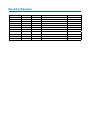
Record of Revision
Version
V1.0.0
Date
March 2012
Page
All
Description
Perliminary Release
Remark
Declaimer
This manual is intended to be used as a practical and informative guide only and
is subject to change without prior notice. It does not represent commitment from
Vecow Co., Ltd. Vecow shall not be liable for direct, indirect, special, incidental, or
consequential damages arising out of the use of the product or documentation,
nor for any infringements upon the rights of third parties, which may result from
such use.
Declaration of Conformity
FCC This equipment has been tested and found to comply with the limits for a Class
A digital device, pursuant to part 15 of the FCC Rules. These limits are designed
to provide reasonable protection against harmful interference when the
equipment is operated in a commercial environment. This equipment generates,
uses, and can radiate radio frequency energy and, if not installed and used in
accordance with the instruction manual, may cause harmful interference to radio
communications. Operation of this equipment in a residential area is likely to
cause harmful interference in which case the user will be required to correct the
interference at his own expense.
CE
The product(s) described in this manual complies with all applicable European
Union (CE) directives if it has a CE marking. For computer systems to remain CE
compliant, only CE-compliant parts may be used. Maintaining CE compliance also
requires proper cable and cabling techniques.
Copyright and Trademarks
This document contains proprietary information protected by copyright. All rights
are reserved. No part of this document may be reproduced by any mechanical,
electronic, or other means in any form without prior written permission of
the manufacturer. Company/product names mentioned herein are used for
identification
©Vecow VSM-200 Video Capture Card Series User Manual
iv
Packing List
No. Photo
1
Description
VSM-200-4/-8 Capture Card
Qty
1
2
VSM-200-4: 16 pin header to D-sub 15 Cable x 1
or
VSM-200-8: 16 pin header to D-sub 15 Cable x 2
3
D-Sub 15 to BNC Cable
1
4
Driver and Software CD
1
Order Information
Part Number Description
VSM-200-4 4-CH, D1, Real-time, SUMIT(PCIe), 120 fps, Video Capture Card, include cables and SDK
VSM-200-8 8-CH, D1, Real-time, SUMIT(PCIe), 240 fps, Video Capture Card, include cables and SDK
Suggestion Platform
Part Number
EC-5500-5GDE
Description
Fanless Embedded Controller with 5x GbE, 2x DDR3 SODIMM, 2x eSATA, 4x COM,
2x MiniPCI-e, 2x HDD, Isolated DIO, SUMIT (A, B), iAMT 7.0
v
Table of Contents
Declaimer
Declaration of Conformity
Copyright and Trademarks
iv
iv
iv
Packing List
Order Information
Suggestion Platform
General Introduction
v
v
v
1
FCC
CE
iv
iv
1.1 Overview
1.2 Product Specification
1
2
1.2.1 Specification of Vecow VSM-200-4
1.2.2 Specification of Vecow VSM-200-8
2
3
1.3 System Requirements
1.4 Mechanical Dimension
4
5
Hardware Installation
6
2.1 Install VSM-200
2.2 Connector Pin Assignments
6
8
2.2.1 Signal Input Pin Assignments
2.2.2 J2 Connector Pin Assignments
8
8
2.3 RCA and BNC Cable Pin Assignment
9
2.3.1 Main board to DB-15 pin assignment
2.3.2 DB15 to 4 Video-in and 4 Audio-in cable pin assignment
9
10
Driver Installation
11
Software Application
14
3.1 Install VSM-200 driver software
11
4.1 Microsoft .NET Frame work installation
4.2 Start the VSM-200 application
4.3 Using the VSM-200 Application
14
15
16
4.3.1 Main Application Window
4.3.2 Camera Setup function
4.3.3 Color Control Function
4.3.4 Audio Downstream Selection
4.3.5 Demonstration
16
18
18
19
19
4.4 Motion Detection
20
4.4.1 Software Interface
4.4.2 Grid Selection Setup
4.4.3 Threshold Interface
20
20
21
SDK Function
23
5.1 Windows
23
5.1.1 Driver Build Guide
5.1.2 Graphedit demo on Window System
5.1.3 Multiple Instance Function
23
25
28
5.2 Linux System
33
5.2.1 Driver Building Guide
33
vi
1
General Introduction
1.1 Overview
Thank you for your purchase of the VSM-200 video capture
card.
The Vecow VSM-200 series, SUMIT™-based, extended
temperature 4-CH/8-CH Video/Audio Capture Card, which
provides outstanding transferring rate for industrial level
systems that require small footprint and steady performance
under harsh environments.
Developed by the by the Small Form Factor special Interest
Group (SFF-SIG™), VSM-200 series feature the Stackable
Unified Module Interconnect Technology (SUMIT) interface.
Main concern of solid, high-speed connector technologies is
small form factors now days.
In order to minimize the board space, VSM-200 series have
closely spaced pins (fine pitch). In addition, the connector
system of VSM-200 series can handle PCI Express and USB
high-frequency signals.
Using 10-bit video analog-to-digital convers, a full 10-bit
video data path, a two dimensional adaptive comb filter for
NTSC, PAL and SECAM video for video quality, and ADCs for
audio quality, VSM-200 series support the bridging of up
to eight channels of digital video and audio from PCIe, and
can output these streams over pins in BT.656 or I2S-style
interfaces, respectively.
General Introduction
1
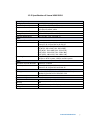
1.2 Product Specification
1.2.1 Specification of Vecow VSM-200-4
General
Bus Type /Form Factor
Dimensions( L x H )
I/O Connector
SUMIT (PCI Express)
90mm x 96mm (3.5" x 3.8")
1 x 16 pin header to D-Sub 15 cable
1 x D-Sub 15 to BNC cable
FCC, CE, RoHS Compliance
-40°C to 85°C (-40 °F to 185 °F)
-25°C to 70°C (-13 °F to 158 °F)
Environment Certifications
Storage Temperature
Operate Temperature
Video
Maximum Channel Number 4
Input Connector
4 input BNC
Resolution
D1 (NTSC: 720 x 480 / PAL: 720 x 576)
CIF (NTSC: 360 x 240 / PAL: 360 x 288)
4CIF (NTSC: 704 x 480 / PAL: 704 x 576)
DCIF (NTSC: 528 x 320 / PAL: 528 x 384)
QCIF (NTSC: 180 x 120 / PAL: 180 x 144)
Recording Rate
4CH with full D1 resolution
120 fps on NTSC system, 100 fps on PAL system
Audio
Maximum Channel Number 4 mono or 2 stereo
Audio Input Connector
4 input RCA
Software
OS Support
WindowsXP/VISTA/Windows7 (32 Bits or 64 Bits)
Standard Linux kernel 2.6.38 and 2.6.33
SDK
VC++ / .NET
Recommend System
CPU
Intel Core2 Duo E4500 2.2GHz
Memory
1GB
Graphics Unit
DirectX 9.0c compatible display card
Storage Size
500GB
©Vecow VSM-200 Video Capture Card Series User Manual
General Introduction
2
1.2.2 Specification of Vecow VSM-200-8
General
Bus Type /Form Factor
Dimensions( L x H )
I/O Connector
SUMIT (PCI Express)
90mm x 96mm (3.5" x 3.8")
2 x 16 pin header to D-Sub 15 cable
2 x D-Sub 15 to BNC cable
FCC, CE, RoHS Compliance
-40°C to 85°C (-40 °F to 185 °F)
-25°C to 70°C (-13 °F to 158 °F)
Environment Certifications
Storage Temperature
Operate Temperature
Video
Maximum Channel Number 8
Input Connector
Channel 1~4: 4 input BNC
Channel 5~8: 4 input BNC to D-Sub 15
Resolution
D1 (NTSC: 720 x 480 / PAL: 720 x 576)
CIF (NTSC: 360 x 240 / PAL: 360 x 288)
4CIF (NTSC: 704 x 480 / PAL: 704 x 576)
DCIF (NTSC: 528 x 320 / PAL: 528 x 384)
QCIF (NTSC: 180 x 120 / PAL: 180 x 144)
Recording Rate
8CH with full D1 resolution
240 fps on NTSC system, 100 fps on PAL system
Audio
Maximum Channel Number 8 mono or 2 stereo
Audio Input Connector
Channel 1~4: 4 input RCA
Channel 5~8: 4 input RCA to D-Sub 15
Software
OS Support
WindowsXP/VISTA/Windows7 (32 Bits or 64 Bits)
Standard Linux kernel 2.6.38 and 2.6.33
SDK
VC++ / .NET
Recommend System
CPU
Intel Core2 GHz Quad Q8400 2.66GHz
Memory
1GB
Graphics Unit
DirectX 9.0c compatible display card
Storage Size
750GB
General Introduction
3
1.3 System Requirements
Your PC must have the following hardware and software
installed to be able to use the VSM-200 series:
• Hardware Requiremets
Item
VSM-200-4
VSM-200-8
CPU
Intel Core 2 Duo
Intel Core 2 Quad
E4500 2.2GHz
Q8400 2.66GHz
Memory
DDR2, 1GB
DDR2, 1GB
Graphics Unit DirectX 9.0c Compatible Display Card
Storage Size
500 GB
750 GB
Slot/Socket
One Available mini PCI-e 1.1
• Software Requirement:
Microsoft® Windows 7 or VISTA operating system or
above.
©Vecow VSM-200 Video Capture Card Series User Manual
General Introduction
4
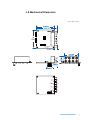
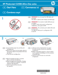
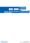
1.4 Mechanical Dimension
Unit: mm (inch)
J2
General Introduction
5
2
Hardware Installation
2.1 Install VSM-200
Power input, GbE ports, COM ports and optional isolated DIO
are located on the rear panel. In this section, we’ll illustrate
connectors on the rear panel.
Step1.
Before you install VSM-200, please power off the system for safty.
Step2.
Insert VSM-200 card into
Sumit slot
©Vecow VSM-200 Video Capture Card Series User Manual
Hardware Installation
6
Step3.
Please make sure PCB
is firmly blocked on the
board.
Step4.
Power On your system and install driver.
Step5.
Connect 16 pin to D-sub
15 Cable for source input.
Detailed pin defination
please refer to 2.1 section.
Hardware Installation
7
2.2 Connector Pin Assignments
The serial console interface connector is a 16 pin header to
D-sub 15 Cable connector. A null modem cable is required
to connect a workstation. 2.2.1 and 2.2.2 show the pin
assignments for the serial console interface connector
2.2.1 Signal Input Pin Assignments
Position
V1
V2
V3
V4
A1
A2
A3
A4
V1
V2
V3
V4
A1
A2
A3
A4
Connector Type
BNC
Signal
Video Source1
Video Source2
Video Source3
Video Source4
Audio Source1
Audio Source2
Audio Source3
Audio Source4
RCA
2.2.2 J2 Connector Pin Assignments
1
3
5
7
9
11
13
15
2
4
6
8
10
12
14
16
Pin No.
Function
Pin No.
Function
1
V5
2
GND
3
V6
4
GND
©Vecow VSM-200 Video Capture Card Series User Manual
5
V7
6
GND
7
V8
8
GND
9
A5
10
GND
11
A6
12
GND
13
A7
14
GND
Hardware Installation
15
A8
16
GND
8
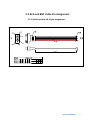
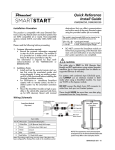
2.3 RCA and BNC Cable Pin Assignment
2.3.1 Main board to DB-15 pin assignment
Driver Installation
9
2.3.2 DB15 to 4 Video-in and 4 Audio-in cable pin assignment
©Vecow VSM-200 Video Capture Card Series User Manual
Driver Installation
10
3
Driver Installation
CAUTION!
The screenshots shown below are taken from Windows 7 and may vary slightly
depending the Operating System
CAUTION!
3.1 Install VSM-200 driver software
Step1.
When you boot your computer after you have installed the VSM-200
PCIe software compression card, Windows will automatically detect the
existing card and the following Device Manager Message dialog appears
automatically. Please click the "Browse my computer for driver software
(advanced)" option.
Driver Installation
11
Step2.
Inser the Software and Driver CD, and click "Browse..." to choose the file
path. The driver folder on the Software and Driver CD is : CD\Windows\
Driver\x86.zip or x64.zip
[x86.zip] for 32 bit version windows system, include XP/Vista/Win7.
[x64.zip] for 64 bit version windows system, include XP/Vista/Win7.
CAUTION!
CAUTION!
When the driver is located, ome windows system will show "Windows Security
Message" to warring you windows can't varify the publisher of this driver software,
please select "Install this driver software anyway" option.
©Vecow VSM-200 Video Capture Card Series User Manual
Driver Installation
12
Step3.
After the driver installation is completed, the windows will pop-up the
message as follow:
Driver Installation
13
4
Software Application
Notice before installing the software:
Make sure your system has installed .NET frame work 2.0
especially the WinXP user. If the program is already installed
you can safely precede the VSM-200 software and skip 4.1
section.
4.1 Microsoft .NET Frame work installation
The Microsoft .NET Frame work will install on windows install
folder. For example, on WinXP SP3, you can check
“Windows\Microsoft.NET\Framework”
folder.
Otherwise, you can get the .NET Frame work here:
http://www.microsoft.com/download/en/details.aspx?id=19
©Vecow VSM-200 Video Capture Card Series User Manual
Software Application
14
4.2 Start the VSM-200 application
Insert the VSM-200 installation and driver disk into your optical
drive. Go to My Computer and double-click the optical drive,
the folder displayed which looks like that shown in the screen
shot below.
There are 32bit and 64bit version of the VSM-200 application,
before you start the execution file, please make sure you
choose the file compatible with your system. Start the VSM200 application by double-click the VSM-200 icon.
VSM-200
Helios Application
Software Application
15
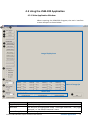
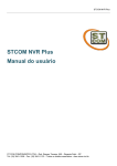
4.3 Using the VSM-200 Application
4.3.1 Main Application Window
When entering the VSM-200 Program, the main interface
screen will open as shown below.
⓬
⓭
❶
❷
❸
❹
❺
Image Display Area
❻
❼
Status of Image fps
❽
❾
Status Area
⓫
❿
Function
Image Display Area
Status area
Status of image fps
Description
Video input image will show in here
The text will be highlighted under "Low-Light Detected", "Day Light
Detected", or "No Motion Detected" status
fps of the image input channel
©Vecow VSM-200 Video Capture Card Series User Manual
Software Application
16
No Function
Description
Main Function
❶ START
Show the Video streaming on Image display area
❷ PAUSE
Pause current video streaming
❸ STOP
Close present video streaming
PROPERTIES
❹ Camera Setup
Show the Video streaming on Image display area
❺ Color Control
Video quality adjustment
❻ Display Mode
Single (1x1)
Show 1 video streaming on image display area
Quad (2x2)
Show 4 video streamings on image display area
Niner (3x3)
Show 9 video streamings on image display area
Hex (4x4)
Show 16 video streamings on image display area
❼ Video Formate
YUV422
Full Color 422 Video display formate option
YUV411
Full Color 411 Video display formate option
Y8
Black/White Video display formate option
❽ Video Standard
NTSC
Video system option
PAL
Video system option
❾ Output size: Every channel image size is control by this setting
720x576
720x240
720x288
352x288
❿ Audio Downstream Enable audio
⓫ Clear
When detection function becomes highlighted text, use this function to
restart it
⓬ Setup
Config the Motion Detection function*
Enable
Checked this option to enable “Motion Detection” function
Grid Selection
Click this item to select motion detection area. Once the cell selection
is done, you need to specify the threshold values as next step
Threhold Settings
An 8-bit programmable value used to determine of this function
⓭ About
Show this software version information
Software Application
17
4.3.2 Camera Setup function
Show the Video streaming on Image display area.
Function
LLC (Line Lock Camera)
Camera 1 to 16 check
box
The BOX of fps
Enable ODD cameras
Enable EVEN cameras
Description
If your CAMERA source support this
function, please checked it.
You can tick the camera source you
want to display.
You can type 1 - 30 to control video
display frame speed.
Enable 1,3,5,7,9,11,13,15 cameras.
Enable 2,4,6,8,10,12,14,16 cameras.
4.3.3 Color Control Function
You can adjust every single video quality by your own.
VDEC_A: CAMERA1,
VDEC_B: CAMERA2,
VDEC_C: CAMERA3,
VDEC_D: CAMERA4,
VDEC_E: CAMERA5,
VDEC_F: CAMERA6,
VDEC_G: CAMERA7,
VDEC_H: CAMERA8,
Press ‘Default’ to restore the original color setting of one
VDEC. After you changed the setting, please press ‘Apply’ to
save it.
©Vecow VSM-200 Video Capture Card Series User Manual
Software Application
18
4.3.4 Audio Downstream Selection
Every audio channel accept 2 audio line input , and every audio
line is apply for one video line. Please see this table.
Audio Line
1
2
3
4
5
6
7
8
Audio Downstream Channel
A
A
B
B
C
C
D
D
Speaker
Left
Right
Left
Right
Left
Right
Left
Right
When you change the setting , must press ‘Apply’ to save it
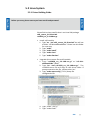
4.3.5 Demonstration
1. Press “CAMERA Setup” to select CAMERA source that you
connect.
2. Select Video Standard: If you do not know your video
system standar, please connect your video device vendor.
3. Select Video format & output size : If you are first running,
please use the default setting.
4. Press “START” to download video streaming.
Software Application
19
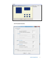
4.4 Motion Detection
4.4.1 Software Interface
On the Main screen of VSM-200 software, press “Setup” and
you will see 3 sub items:
Enable
Checked this option to enable “Motion
Detection” function.
Grid Selection
Click this item to select motion detection
area. Once the cell selection is done,
you need to specify the threshold values
as next step.
ThresholdSettings
An 8-bit programmable value used to
determine of this function.
4.4.2 Grid Selection Setup
Point1.
When open this
option , the “Motion
Detection Area
Selection “ will show
empty grid table
Point2.
Use “Ctrl ” key can get
different grid
Use “Shift ” key can
get continuous area.
©Vecow VSM-200 Video Capture Card Series User Manual
Software Application
20
Point3.
Multiple areas are
acceptable.
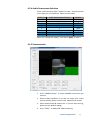
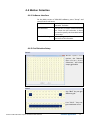
4.4.3 Threshold Interface
Motion
No Motion
Black / Low Light
White / Day Light
Software Application
21
Motion
The motion detection threshold is an 8-bit programmable value
used to determine the presence of motion. This value represents
a minimum delta between scaled block average luma values to
indicate motion within a block. The motion number of blocks
detected threshold is an 8-bit programmable register field that
controls how many blocks must detect motion before the frame
comparison indicates motion detected to the host and external
interrupts.
No Motion
The still image threshold is an 8-bit programmable value used to
determine a non-changing image. This value represents a maximum
delta between scaled block average luma values to indicate a
constant image within a block. The still number of blocks detected
threshold register field indicates how many of the 192 grid regions
detected a still image. The still frame threshold register field controls
how many blocks per frame must detect a still image to cause the
still image frame counter to increment. The still frame threshold
field controls how many consecutive still frames are required before
the interrupt is asserted.
Black/Low Light & Black and white detection is performed on each field/frame that is
White / Day Light used for motion detection. In order to detect the black and white,
the following thresholds and limits are used:
i. For every pixel of the field indicated by the top_bot_field_sel
register field of the MDET_{x}_CTRL register, if the luma value is
less than the black threshold, the black detection counter will be
incremented.
ii. If the luma value is greater than the white threshold, the white
detection counter will be incremented.
iii. If, at the end of the field, the black detection counter is greater
than the black field limit value, a black detection will be signaled for
that channel.
iiii. If, at the end of the field, the white detection counter is greater
than the white field limit value, a white detection will be signaled
for that channel. The black and white detection counters will be
reset before the beginning of the next field for detection.
©Vecow VSM-200 Video Capture Card Series User Manual
Software Application
22
5
SDK Function
5.1 Windows
5.1.1 Driver Build Guide
Before starting to build VSM-200 driver please ensure that you
have installed the following development environment:
1. Visual Studio 2005 or later
2. Microsoft WDK 6000. More information on the following
link http://www.microsoft.com/whdc/resources/downloads.mspx
3. Microsoft Windows Vista Software Development Kit.
While installing the SDK give simple pathname (for e.g.
SDK3.0) more information on the following link
http://www.microsoft.com/downloads/en/
details.aspx?familyid=4377F86D-C913-4B5C-B87E
F72E5B4E065&displaylang=en
After the installation on the VSM-200 SDK main directory
create a batch file with the following contents. Let’s assume
the batch file name is ‘setpath.bat’.
SET SDKROOT = (Full Directory path containing Windows Vista SDK e.g. C:\SDK3.0)
SET WDKROOT = (Full Directory path containing WDK e.g. C:\WINDDK\6000)
*Please run this batch file before compiling some of the modules s stated below.*
• Modules in the CX25820/1 driver sources
Capture and HeliosApp are the modules that comprise
the full CX25820/1 software driver and application system.
Please follow the steps to install:
SDK
23
CAUTION!
CAUTION!
Before compiling Application software you need to the DirectShow base class. First, add
DirectShow base class path to Visual Studio 2005 project. Secondly, add include path as
the shot below:
Thirdly, add library path:
Once the path for includes and libraries are set properly, you can start to compile the
application to get the executable software.
• Compiler the cx25858 driver source
Open “Capture” module on source project.
1. Invoke your build environment as your target O.S
2. Change directory to SDK\Capture.
3. At the command prompt run the setpath.bat
4. Run the build utility with following options, build –c
• Build VSM-200 software
Open “HeliosApp” module on source project.
©Vecow VSM-200 Video Capture Card Series User Manual
SDK
24
5.1.2 Graphedit demo on Window System
The Microsoft DirectX SDK provides a very useful debugging
utility called GraphEdit, which can be used to create Media
device model. The demo of download video streaming with
GraphEdit step:
Step1.
Insert filter
From the Graph menu
of the GraphEdit
application, click
Insert Filters… and
choose the desired
filters.
Step2.
Add Crossbar Device
Step3.
Add Capture Device
Step4.
Goto the “DirectShow
filter ” class and get
next filter.
SDK
25
Step5.
A d d v i d e o co nve r t
device.
Step6.
Add Video Renderer
Step7.
Connect all device as below
Step8.
Play
Press play to show the
image
Step9.
Display image
©Vecow VSM-200 Video Capture Card Series User Manual
SDK
26
Step10. Setup the properties of filter
The properties of
Crossbar device
The properties of
Capture device
The properties of
Video Converter
SDK
27
5.1.3 Multiple Instance Function
On legacy capture card, one Video channel is only assign to
one PCI video device. Although VSM-200 has multiple video
channels, on Windows Device Manager you can only see one
PCI device. In order to separate video streams from one video
device, we are promote the “Multiple Instance” function.
Please follow the step to enable “Multiple Instance” function
on your system.
Step1.
We strongly suggest uninstalling current VSM-200 driver from Windows, but
if new installed, please skipping this step.
Please tick this box,
and clear all driver
files.
©Vecow VSM-200 Video Capture Card Series User Manual
SDK
28
Step2.
Modify driver for multiple instance function. Please find the "CxAtlas.inf"
and open it with Notpad. Goto the 118 line, you will see the text shows as
below:
‘HKR,"DriverData","EnableMultiInstances",0x00010001, 0x00, 0x00,
0x00, 0x00’
Please change 2nd value "0x00" to "0x01", the text as below:
‘HKR,"DriverData","EnableMultiInstances",0x00010001, 0x01, 0x00, 0x00,
0x00’
Please save your change and exit the Notepad.
Step3.
Re-install the VSM-200 driver with modified driver, please refer to chapter 3
Driver Installation.
SDK
29
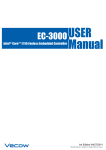
Step4.
Testing Multiple Instance function with GraphEdit, as you can see the chart below:
©Vecow VSM-200 Video Capture Card Series User Manual
SDK
30
When enable multiple instance, you can create four CX25858 capture device. Please refer
as upon figure.
SDK
31
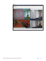
Step5.
Play the Graph, there are four separate vidoe windows shows as follow
graphics:
©Vecow VSM-200 Video Capture Card Series User Manual
SDK
32
5.2 Linux System
CAUTION!
CAUTION!
5.2.1 Driver Building Guide
Before you start, please ensure you have root ID and password.
Please find as these two file that is on Linux SDK package
v4l2_source_2.6.33.tar.bz2
cx25858_src_2.0.108.tar.gz
• Install v4l2 module
1. Type “tar -jxvf v4l2_source_2.6.33.tar.bz2”You will see
a folder “v4l-dvb-abd3aac6644e”. Please into this folder
for next step.
2. Type “make”
3. Type “make install”
4. Type “make clean”
5. Type “make distclean”
• Upgrade driver source file to v4l2 module
1. Copy “cx25858_src_2.0.108.tar.gz” to “v4l-dvbabd3aac6644e” folder.
2. Type “tar –zxvf cx25858_src_2.0.108.tar.gz”. The
cx25858 source file will copy to v4l2 driver folder. If
prompt overwrite the file , please select ‘yes’.
3. Type “make menuconfig” ( PS*1) Setup the
configuration file
4. Type “make” ( PS*2)
5. Type “make install”
SDK
33
• Install driver module
1. Change to ““v4l-dvb-abd3aac6644e/v4l” folder.
2. Type “modprobe cx25858”
3. Type “modprobe cx25858-alsa”. This is cx25858 audio
module , that use ALSA function. (ALSA: Advanced Linux
Sound Architecture)
• Check driver
1. Type “lsmod” to check cx25858 driver.
2. Type “dmesg” to see cx25858 driver status.
• Display the video stream
1. Change to ““v4l-dvb-abd3aac6644e/linux/scrips” folder
2. Use script command “mplay_video #” . ( # is 0~7 , for
video 1 to video 8)
For example : Display Video 1 , type “maply_video 0”
Display Video 5 , type “maply_video 4”
Please refer the display image as below:
©Vecow VSM-200 Video Capture Card Series User Manual
SDK
34