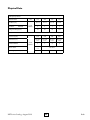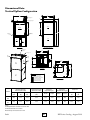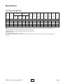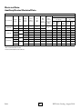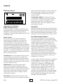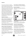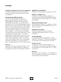
1
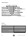
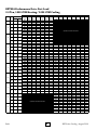
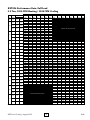
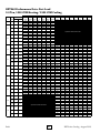
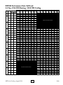
ROTH TerraStar Heat Pumps V-Series WATER-TO-AIR Two-Stage, R-410a Packaged Vertical Unit Specification Catalog P/N 2300100903 Call 888-266-7684 US or 800-969-7684 CAN or visit our website at www.roth-america.com ...Your environment is our business... Table of Contents: Product Introduction & Unit Features................................................................................................................. 2 Performance Data: AHRI - Single Compressor.................................................................................................... 3 Unit Nomenclature: Vertical Cabinets................................................................................................................. 4 Glossary................................................................................................................................................................. 4 Calculations, Water Flow Selection, & Performance Data Notes....................................................................... 5 Performance Data: RXT036 - Part Load Heating and Cooling........................................................................... 6 Performance Data: RXT036 - Full Load Heating and Cooling............................................................................ 7 Performance Data: RXT048 - Part Load Heating and Cooling........................................................................... 8 Performance Data: RXT048 - Full Load Heating and Cooling............................................................................ 9 Performance Data: RXT060 - Part Load Heating and Cooling.........................................................................10 Performance Data: RXT060 - Full Load Heating and Cooling..........................................................................11 Performance Data: RXT072 - Part Load Heating and Cooling.........................................................................12 Performance Data: RXT072 - Full Load Heating and Cooling..........................................................................13 Correction Factors...............................................................................................................................................14 Physical Data.......................................................................................................................................................15 Dimensional Data...............................................................................................................................................16 Electrical Data.....................................................................................................................................................17 Auxiliary Electric Heater Data............................................................................................................................18 Controls......................................................................................................................................................... 19-26 Blower Data.........................................................................................................................................................24 Wiring Diagrams.................................................................................................................................................25 Engineering Specifications.................................................................................................................................26 Accessories..........................................................................................................................................................27 Warranty..............................................................................................................................................................28 Revision Table.....................................................................................................................................................30 RXT Series Catalog - August 2010 1 Roth Product Introduction & Unit Features Unit Features at a Glance • Non-Ozone Depleting R-410A Refrigerant • Rugged Multi-Position Powder Coated Steel Cabinet Construction with Two-Tone Accent Panels • All Panels Removable for Easy Service • Coated Air Coils For Extended Life • Bidirectional Expansion Valve • ECM Blower Motor • Corrosion-Proof, Stainless Steel Drain Pan • ETL Certified to UL & CSA Standards • AHRI Certified to ISO Standards • Copper Coaxial Water Heat Exchanger • Flow Switch Protected • Fault Retry To Eliminate Nuisance Service Calls • High Efficiency Copeland UltraTech Scroll Compressor • 10 Year Limited Residential Warranty Roth is turning the geothermal heat pump industry in a new direction! Roth’s® RXT Series is the first ever multi-position packaged geothermal heat pump, providing the ultimate in flexibility for distributors and dealers. The appliance style, quiet operation, and ultra high efficiencies will certainly please homeowners, too. The RXT series was designed with the dealer and distributor in mind, but the homeowner will benefit as a result. Some of the industry-leading features and benefits are listed below. • Appliance grade cabinet looks like no other geothermal heat pump on the market. The twotoned access panels with rounded corners will be a hit with consumers, but are also near airtight, increasing indoor air quality. • Quadruple compressor isolation (high density steel/foam layer, rubber grommets, and two layers of insulation) provides the best combination of sound/vibration absorption available, making RXT the quietest geothermal heat pump available. • Patent-pending design provides a foamed-in water-to-refrigerant coaxial heat exchanger that not only prevents condensation, potentially leading to premature failure, but also includes a sleeved opening for downflow configuration. This feature means higher reliability and less SKUs. • Rail mounted blower assembly makes conversion from upflow to downflow a breeze, and increases serviceability. • Remote-mount control box provides eye level access for easier wiring and service, and also allows the unit to be installed as left hand or right hand return. • Stainless steel drain pan and e-coated air coil increase unit life expectancy. • Copeland® UltraTech® two-stage compressor and variable speed ECM fan motor adjust to heating and cooling requirements, contributing to unmatched comfort. • The best available warranty in the industry insures peace of mind. The ten-year standard warranty coupled with a lifetime cabinet, coaxial heat exchanger, and compressor warranty (to the original owner) is head and shoulders above any geothermal product on the market today. • Heat exchanger design and component selection combine to create extremely high cooling EER and some of the highest heating capacities and COPs on the market today. Roth Optional features • Hot Water Generator (Desuperheater) • Field Installed Internal Electric Heat • CuproNickel Heat Exchanger 2 RXT Series Catalog - August 2010 Unit Performance: AHRI Data - Single Compressor Units Ground Loop Heat Pump Model RXT024 RXT036 RXT048 RXT060 RXT072 Capacity Heating Btu/hr Full Load Cooling COP Btu/hr EER Future Model Part Load Full Load 28,500 4.1 38,900 18.2 Part Load 22,000 4.8 29,000 28.4 Full Load 42,500 4.0 53,500 17.7 Part Load 33,500 4.7 42,400 25.2 Full Load 50,000 3.8 65,500 17.6 Part Load 39,500 4.3 48,600 23.5 Full Load 60,000 3.9 70,000 15.6 Part Load 50,000 4.3 56,500 20.3 Note: Rated in accordance with ISO Standard 13256-1 which includes Pump Penalties. Heating capacities based on 68.0°F DB, 59.0°F WB entering air temperature. Cooling capacities based on 80.6°F DB, 66.2°F WB entering air temperature. Entering water temperatures Full Load: 32°F heating / 77°F cooling. Entering water temperatures Part Load: 41°F heating / 68°F cooling. Ground Water Heat Pump Model RXT024 RXT036 RXT048 RXT060 RXT072 Capacity Heating Btu/hr Full Load Cooling COP Btu/hr EER Future Models Part Load Full Load 34,300 4.5 39,800 22.0 Part Load 23,800 5.1 29,000 32.2 Full Load 53,300 4.6 56,500 21.7 Part Load 37,600 5.1 43,100 28.7 Full Load 61,200 4.5 67,200 20.9 Part Load 43,900 4.8 50,700 27.3 Full Load 73,600 4.4 72,300 18.3 Part Load 54,300 4.6 57,900 23.1 Note: Rated in accordance with ISO Standard 13256-1 which includes Pump Penalties. Heating capacities based on 68.0°F DB, 59.0°F WB entering air temperature. Cooling capacities based on 80.6°F DB, 66.2°F WB entering air temperature. Entering water temperatures: 50°F heating / 59°F cooling. RXT Series Catalog - August 2010 3 Roth Roth Geothermal Heat Pumps 2010 Models - Water-to-Air 2-stage Vertical Unit Nomenclature: Rev. 08JUL2010 1 2 3 456 7 8 9 10 11 12 13 14 15 R X T 048 A 1 1 M M 1 C SS Brand R = Roth Other Options SS = Standard Type X = Multi-position Vertical Heat Exchanger Options C = Copper coax (with e-coated air coil) N = CuNi coax (with e-coated air coil) Stages T = Two-stage Blower Options 1 = ECM Unit Capacity Nominal MBTUH 024,036,048,060,072 Discharge Air Configuration M = Multi-position Series A = Current Revision Return Options M = Multi-position Voltage 1 = 208/230 Volts, 60 Hz, 1ph RESIDENTIAL Hot Water Options 0 = No Desuperheater 1 = With Desuperheater & int. pump Glossary Glossary of Terms CFM = Airflow, Cubic Feet/Minute HR = Total Heat Of Rejection, Btu/hr COP = Coefficient of Performance = BTU Output / BTU Input KW = Total Power Unit Input, Kilowatts DH = Desuperheater Capacity, Btu/hr LAT = Leaving Air Temperature, Fahrenheit EAT = Entering Air Temperature, Fahrenheit (Dry Bulb/Wet Bulb) LC = Latent Cooling Capacity, Btu/hr EER = Energy Efficiency Ratio = BTU output/Watts input SC = Sensible Cooling Capacity, Btu/hr EWT = Entering Source Water Temperature, Fahrenheit LWT = Leaving Source Water Temperature, Fahrenheit ELT = Entering Load Water Temperature, Fahrenheit LLT = Leaving Load Water Temperature, Fahrenheit GPM = Water Flow, Gallons Per Minute TC = Total Cooling Capacity, Btu/hr HC = Total Heating Capacity, Btu/hr WPD = Water Pressure Drop, PSI & Feet of Water HE = Total Heat Of Extraction, Btu/hr Roth 4 RXT Series Catalog - August 2010 Calculations, Water Flow Selection, & Performance Data Notes Heating & Cooling Calculations Heating Cooling LAT = EAT + HC CFM x 1.08 LAT (DB) = EAT (DB) SC CFM x 1.08 LWT = EWT HE GPM x 500 LWT = EWT + HR GPM x 500 LC = TC - SC Water Flow Selection Proper flow rate is crucial for reliable operation of geothermal heat pumps. The performance data shows three flow rates for each entering water temperature (EWT column). The general “rule of thumb” when selecting flow rates is the following: Calculate the temperature difference (TD) based upon the HE and GPM of the model (step 4). TD = HE / (GPM x 500). Calculate the LWT (step 6). LWT = EWT - TD. Top flow rate: Open loop systems (1.5 to 2.0 gpm per ton) Middle flow rate: Minimum closed loop system flow rate (2.25 to 2.50 gpm/ton) Bottom flow rate: Nominal (optimum) closed loop system flow rate (3.0 gpm/ton) If the LWT is below 35-38°F, there is potential for freezing conditions if the flow rate or water temperature is less than ideal conditions, and the flow rate must be increased. Example 1: EWT = 50°F. Model RXT048, high capacity. Flow rate = 6 GPM. Air Flow = 1500 CFM. HE = 36,700 Btuh. TD = 36,700 / (6 x 500) = 12.2°F LWT = 50 - 12.2 = 37.8°F Since the water flow is leaving at approximately 38°F, the flow rate is acceptable. Although the “rule of thumb” is adequate in most areas of North America, it is important to consider the application type before applying this “rule of thumb.” Antifreeze is generally required for all closed loop (geothermal) applications. Extreme Southern U.S. locations are the only exception. Open loop (well water) systems cannot use antifreeze, and must have enough flow rate in order to avoid freezing conditions at the Leaving Source Water Temperature (LWT) connection. Calculations must be made for all systems without antifreeze to determine if the top flow rate is adequate to prevent LWT at or near freezing conditions. The following steps should taken in making this calculation: Example 2: EWT = 40°F. Model RXT048, high capacity. Flow rate = 6 GPM. Air Flow = 1500 CFM. HE = 36,700 Btuh. TD = 36,700 / (6 x 500) = 12.2°F LWT = 40 - 12.2 = 27.8°F Water flow rate must be increased to avoid freezing. Determine minimum EWT based upon your geographical area. Go to the performance data table for the heat pump model selected and look up the the Heat of Extraction (HE) at the “rule of thumb” water flow rate (GPM) and at the design Entering Air Temperature (EAT). Performance Data Notes 1. Capacity data includes water pumping watts and is based upon 15% (by volume) propylene glycol antifreeze solution. 2. Desuperheater capacity is based upon 0.4 GPM Flow per nominal ton at 90°F entering hot water temperature. 3. Interpolation between above categories is permissible; extrapolation is not. 4. See Flow Rate Selection above for proper application. RXT Series Catalog - August 2010 5 Roth RXT036 Performance Data: Part Load 3.0 Ton, 1050 CFM Heating / 1050 CFM Cooling Heating WPD PSI FT EWT °F Flow GPM 25 9.0 4.4 10.2 4.5 1.0 2.3 7.0 2.5 5.8 9.0 4.2 9.7 4.5 1.0 2.3 7.0 2.3 5.3 9.0 3.9 9.0 4.5 0.9 2.1 7.0 2.2 5.1 9.0 3.6 8.3 4.5 0.8 1.8 7.0 2.0 4.6 9.0 3.3 7.6 4.5 0.8 1.8 7.0 1.9 4.4 9.0 3.1 7.2 4.5 0.7 1.6 7.0 1.8 4.2 9.0 2.9 6.7 4.5 0.7 1.6 7.0 1.7 3.9 9.0 2.8 6.5 4.5 0.6 1.4 7.0 1.6 3.7 9.0 2.6 6.0 4.5 0.6 1.4 7.0 1.5 3.5 9.0 2.4 5.5 30 40 50 60 70 80 90 100 Airow CFM 850 1050 850 1050 850 1050 850 1050 850 1050 850 1050 850 1050 850 1050 850 1050 850 1050 850 1050 850 1050 850 1050 850 1050 850 1050 850 1050 850 1050 850 1050 850 1050 850 1050 850 1050 850 1050 HC HE MBtuh MBtuh 17.3 17.5 17.9 18.2 18.6 18.9 18.7 19.0 20.7 21.0 21.5 21.8 21.6 21.9 23.5 23.9 24.4 24.8 24.5 24.9 26.3 26.7 27.3 27.7 27.4 27.8 29.0 29.4 30.0 30.5 30.2 30.6 31.5 32.0 32.7 33.2 32.8 33.3 33.9 34.4 35.1 35.7 35.3 35.8 12.0 12.3 12.6 13.0 13.3 13.7 13.4 13.8 15.3 15.8 16.1 16.6 16.2 16.7 18.1 18.6 18.9 19.5 19.0 19.6 20.8 21.4 21.8 22.3 21.9 22.5 23.4 24.0 24.4 25.1 24.6 25.2 25.9 26.5 27.1 27.7 27.2 27.8 28.2 28.9 29.4 30.2 29.6 30.3 LAT °F 88.8 85.4 89.5 86.0 90.3 86.7 90.4 86.8 92.5 88.5 93.4 89.2 93.5 89.3 95.6 91.1 96.6 91.9 96.7 92.0 98.6 93.5 99.7 94.4 99.8 94.5 101.6 95.9 102.7 96.9 102.9 97.0 104.3 98.2 105.6 99.3 105.7 99.4 106.9 100.3 108.2 101.5 108.5 101.6 kW 1.55 1.51 1.56 1.52 1.56 1.52 1.56 1.52 1.57 1.53 1.58 1.53 1.57 1.53 1.59 1.54 1.60 1.56 1.60 1.56 1.61 1.56 1.61 1.57 1.61 1.56 1.63 1.58 1.63 1.59 1.63 1.58 1.64 1.60 1.65 1.60 1.64 1.60 1.66 1.61 1.66 1.62 1.66 1.61 COP W/W DH MBtuh 3.27 3.40 3.36 3.51 3.49 3.64 3.51 3.66 3.86 4.02 3.99 4.17 4.03 4.19 4.33 4.55 4.47 4.66 4.49 4.68 4.79 5.01 4.97 5.17 4.99 5.22 5.21 5.45 5.39 5.62 5.43 5.67 5.63 5.86 5.81 6.08 5.86 6.10 5.98 6.26 6.20 6.46 6.23 6.52 2.3 2.3 2.4 2.4 2.5 2.5 2.5 2.5 2.7 2.8 2.9 2.9 2.9 3.0 3.0 3.1 3.2 3.3 3.2 3.3 3.5 3.6 3.6 3.6 3.6 3.8 3.8 3.9 3.9 4.0 3.9 4.0 4.2 4.2 4.3 4.3 4.4 4.5 4.4 4.5 4.6 4.7 4.7 4.8 Operation Not Recommended 110 Airow CFM TC SC MBtuh MBtuh Cooling HR MBtuh S/T kW EER DH Btuh/W MBtuh Operation Not Recommended 850 1050 850 1050 850 1050 850 1050 850 1050 850 1050 850 1050 850 1050 850 1050 850 1050 850 1050 850 1050 850 1050 850 1050 850 1050 850 1050 850 1050 850 1050 850 1050 850 1050 850 1050 29.4 30.3 29.9 30.7 30.0 30.9 28.2 29.1 28.7 29.5 28.8 29.6 26.9 27.7 27.3 28.2 27.5 28.3 25.6 26.3 25.9 26.7 26.1 26.8 24.1 24.8 24.4 25.1 24.5 25.3 22.5 23.1 22.8 23.5 22.9 23.6 20.8 21.4 21.1 21.7 21.2 21.8 20.6 22.0 20.8 22.1 20.6 22.0 19.9 21.2 20.1 21.4 19.9 21.2 19.3 20.6 19.5 20.7 19.3 20.6 18.7 19.9 18.9 20.1 18.7 19.9 18.1 19.3 18.2 19.4 18.1 19.3 17.4 18.6 17.6 18.7 17.4 18.6 16.7 17.7 16.8 17.9 16.6 17.7 0.70 0.73 0.70 0.72 0.69 0.71 0.71 0.73 0.70 0.73 0.69 0.72 0.72 0.74 0.71 0.73 0.70 0.73 0.73 0.76 0.73 0.75 0.72 0.74 0.75 0.78 0.75 0.77 0.74 0.76 0.77 0.81 0.77 0.80 0.76 0.79 0.80 0.83 0.80 0.82 0.78 0.81 32.8 33.9 33.1 34.1 33.2 34.2 32.1 33.2 32.4 33.3 32.4 33.4 31.3 32.3 31.4 32.5 31.6 32.6 30.6 31.5 30.6 31.6 30.7 31.6 29.8 30.8 29.8 30.7 29.8 30.8 29.0 29.9 28.9 29.9 28.9 29.9 28.1 29.1 28.0 29.0 28.0 29.0 1.01 1.06 0.95 1.00 0.93 0.98 1.13 1.19 1.07 1.12 1.05 1.10 1.28 1.35 1.21 1.27 1.19 1.25 1.46 1.53 1.38 1.45 1.35 1.42 1.66 1.75 1.57 1.65 1.54 1.62 1.89 1.99 1.79 1.88 1.75 1.84 2.15 2.26 2.03 2.14 1.99 2.10 29.1 28.6 31.5 30.7 32.3 31.5 25.0 24.5 26.8 26.3 27.4 26.9 21.0 20.5 22.6 22.2 23.1 22.6 17.5 17.2 18.8 18.4 19.3 18.9 14.5 14.2 15.5 15.2 15.9 15.6 11.9 11.6 12.7 12.5 13.1 12.8 9.7 9.5 10.4 10.1 10.7 10.4 2.4 2.6 2.3 2.4 2.2 2.3 3.0 3.2 2.7 2.9 2.6 2.8 3.5 3.7 3.2 3.4 3.1 3.3 3.9 4.2 3.7 3.9 3.6 3.8 4.4 4.7 4.1 4.4 3.9 4.2 4.9 5.2 4.6 4.9 4.4 4.7 5.4 5.7 5.1 5.4 4.9 5.2 Heating data based on 70F EAT; Cooling data based on 80/67F EAT. See Correction Factors on page 14 for different conditions. Roth 6 RXT Series Catalog - August 2010 RXT036 Performance Data: Full Load 3.0 Ton, 1300 CFM Heating / 1300 CFM Cooling Heating WPD PSI FT EWT °F Flow GPM 25 9.0 4.4 10.2 4.5 1.0 2.3 7.0 2.5 5.8 9.0 4.2 9.7 4.5 1.0 2.3 7.0 2.3 5.3 9.0 3.9 9.0 4.5 0.9 2.1 7.0 2.2 5.1 9.0 3.6 8.3 4.5 0.8 1.8 7.0 2.0 4.6 9.0 3.3 7.6 4.5 0.8 1.8 7.0 1.9 4.4 9.0 3.1 7.2 4.5 0.7 1.6 7.0 1.8 4.2 9.0 2.9 6.7 4.5 0.7 1.6 7.0 1.7 3.9 9.0 2.8 6.5 4.5 0.6 1.4 7.0 1.6 3.7 9.0 2.6 6.0 4.5 0.6 1.4 7.0 1.5 3.5 9.0 2.4 5.5 30 40 50 60 70 80 90 100 Airow CFM 1050 1300 1050 1300 1050 1300 1050 1300 1050 1300 1050 1300 1050 1300 1050 1300 1050 1300 1050 1300 1050 1300 1050 1300 1050 1300 1050 1300 1050 1300 1050 1300 1050 1300 1050 1300 1050 1300 1050 1300 1050 1300 1050 1300 HC HE MBtuh MBtuh 25.6 18.3 27.1 19.6 24.5 17.4 26.0 18.6 27.0 19.6 28.6 21.0 27.5 20.0 29.1 21.4 27.8 20.4 29.5 21.8 30.7 22.9 32.5 24.5 31.3 23.6 33.2 25.2 31.2 23.5 33.1 25.1 34.3 26.3 36.4 28.1 35.0 26.8 37.1 28.7 34.5 26.4 36.6 28.2 38.0 29.5 40.3 31.6 38.8 30.2 41.1 32.3 37.8 29.3 40.1 31.3 41.7 32.8 44.2 35.1 42.5 33.5 45.0 35.8 41.2 32.2 43.7 34.5 45.4 36.0 48.1 38.5 46.2 36.7 49.0 39.3 44.6 35.1 47.3 37.6 49.2 39.3 52.1 42.0 50.1 40.2 53.1 43.0 LAT °F 92.5 89.3 91.6 88.5 93.8 90.4 94.2 90.7 94.5 91.0 97.0 93.1 97.6 93.6 97.5 93.6 100.3 95.9 100.9 96.4 100.4 96.1 103.5 98.7 104.2 99.3 103.4 98.6 106.8 101.5 107.4 102.1 106.4 101.1 110.0 104.3 110.8 104.9 109.3 103.7 113.3 107.1 114.2 107.8 kW 2.25 2.21 2.20 2.16 2.28 2.23 2.29 2.25 2.29 2.25 2.37 2.33 2.39 2.35 2.40 2.35 2.48 2.43 2.50 2.45 2.51 2.46 2.59 2.54 2.61 2.57 2.63 2.58 2.72 2.67 2.74 2.69 2.76 2.71 2.85 2.80 2.88 2.83 2.91 2.85 3.00 2.95 3.03 2.97 COP W/W 3.33 3.59 3.27 3.53 3.47 3.76 3.51 3.79 3.56 3.84 3.79 4.09 3.84 4.14 3.81 4.13 4.06 4.39 4.10 4.44 4.03 4.36 4.30 4.65 4.35 4.69 4.21 4.55 4.49 4.85 4.54 4.90 4.38 4.72 4.67 5.03 4.70 5.07 4.49 4.86 4.80 5.17 4.84 5.24 Operation Not Recommended 110 DH MBtuh 3.6 3.6 3.5 3.5 3.8 3.8 3.8 3.8 4.0 4.1 4.3 4.3 4.4 4.5 4.4 4.4 4.8 4.8 4.9 4.9 4.9 5.1 5.3 5.4 5.4 5.4 5.3 5.3 5.8 5.8 5.9 5.9 5.8 6.0 6.4 6.4 6.5 6.4 6.2 6.2 6.9 6.9 7.0 7.0 Airow CFM TC SC MBtuh MBtuh Cooling HR S/T MBtuh kW EER DH Btuh/W MBtuh Operation Not Recommended 1050 1300 1050 1300 1050 1300 1050 1300 1050 1300 1050 1300 1050 1300 1050 1300 1050 1300 1050 1300 1050 1300 1050 1300 1050 1300 1050 1300 1050 1300 1050 1300 1050 1300 1050 1300 1050 1300 1050 1300 1050 1300 40.7 41.7 41.4 42.4 41.6 42.6 39.3 40.3 40.0 41.0 40.2 41.2 37.8 38.8 38.5 39.4 38.7 39.6 36.2 37.1 36.8 37.7 36.9 37.9 34.2 35.0 34.7 35.6 34.9 35.8 31.8 32.6 32.3 33.1 32.5 33.3 28.9 29.7 29.4 30.2 29.6 30.3 26.7 29.2 26.7 29.2 26.8 29.3 26.2 28.6 26.2 28.6 26.2 28.7 25.7 28.1 25.7 28.1 25.8 28.2 25.1 27.4 25.1 27.5 25.2 27.5 24.4 26.6 24.4 26.6 24.4 26.7 23.3 25.4 23.3 25.4 23.4 25.5 21.7 23.8 21.8 23.8 21.8 23.8 0.66 0.70 0.64 0.69 0.64 0.69 0.67 0.71 0.66 0.70 0.65 0.70 0.68 0.72 0.67 0.71 0.67 0.71 0.69 0.74 0.68 0.73 0.68 0.73 0.71 0.76 0.70 0.75 0.70 0.75 0.73 0.78 0.72 0.77 0.72 0.77 0.75 0.80 0.74 0.79 0.74 0.79 47.2 48.6 47.6 49.1 47.6 49.0 46.3 47.8 46.8 48.2 46.8 48.2 45.4 47.0 45.9 47.3 45.8 47.2 44.6 46.0 44.9 46.3 44.7 46.2 43.4 44.8 43.6 45.1 43.5 44.9 42.0 43.5 42.1 43.6 42.0 43.4 40.3 41.8 40.4 41.9 40.2 41.6 1.89 2.02 1.82 1.95 1.76 1.88 2.06 2.20 1.99 2.12 1.92 2.05 2.24 2.39 2.16 2.31 2.09 2.23 2.45 2.62 2.36 2.52 2.28 2.44 2.69 2.88 2.60 2.77 2.51 2.68 2.98 3.19 2.88 3.07 2.78 2.97 3.33 3.55 3.21 3.43 3.10 3.31 21.5 20.6 22.7 21.7 23.6 22.7 19.1 18.3 20.1 19.3 20.9 20.1 16.9 16.2 17.8 17.1 18.5 17.8 14.8 14.2 15.6 15.0 16.2 15.5 12.7 12.2 13.3 12.9 13.9 13.4 10.7 10.2 11.2 10.8 11.7 11.2 8.7 8.4 9.2 8.8 9.5 9.2 3.2 3.5 3.0 3.3 2.8 3.1 3.9 4.3 3.7 4.0 3.5 3.8 4.6 5.0 4.3 4.7 4.1 4.5 5.2 5.7 4.9 5.4 4.8 5.2 5.9 6.4 5.5 6.0 5.4 5.9 6.4 7.0 6.1 6.7 5.9 6.4 6.9 7.6 6.7 7.3 6.3 6.9 Heating data based on 70F EAT; Cooling data based on 80/67F EAT. See Correction Factors on page 14 for different conditions. RXT Series Catalog - August 2010 7 Roth RXT048 Performance Data: Part Load 4.0 Ton, 1400 CFM Heating / 1400 CFM Cooling WPD PSI FT EWT °F Flow GPM 25 9.0 4.8 11.1 4.5 1.1 2.5 7.0 2.8 6.5 9.0 4.6 10.6 4.5 1.1 2.5 7.0 2.6 6.0 9.0 4.2 9.7 4.5 1.0 2.3 7.0 2.4 5.5 9.0 4.0 9.2 4.5 0.9 2.1 7.0 2.3 5.3 9.0 3.7 8.5 4.5 0.9 2.1 7.0 2.1 4.9 9.0 3.5 8.1 4.5 0.8 1.8 7.0 2.0 4.6 9.0 3.4 7.9 4.5 0.8 1.8 7.0 2.0 4.6 9.0 3.3 7.6 4.5 0.8 1.8 7.0 1.9 4.4 9.0 3.2 7.4 4.5 0.8 1.8 7.0 1.9 4.4 9.0 3.1 7.2 30 40 50 60 70 80 90 100 Airow CFM HC HE MBtuh MBtuh Heating LAT °F 1150 1400 1150 1400 1150 1400 1150 1400 1150 1400 1150 1400 1150 1400 23.1 26.1 23.5 26.5 24.9 28.0 25.5 28.7 27.7 31.2 29.3 33.0 30.0 33.8 16.0 18.8 16.3 19.2 17.7 20.6 18.3 21.3 20.4 23.7 21.9 25.4 22.6 26.2 88.6 87.3 88.9 87.5 90.0 88.5 90.5 89.0 92.3 90.6 93.6 91.8 94.2 92.4 kW 2.09 2.14 2.10 2.15 2.12 2.17 2.12 2.17 2.15 2.20 2.17 2.22 2.18 2.22 1150 1400 1150 1400 1150 1400 1150 1400 1150 1400 1150 1400 1150 1400 1150 1400 1150 1400 1150 1400 1150 1400 1150 1400 1150 1400 1150 1400 1150 1400 31.7 35.7 33.5 37.8 34.3 38.7 35.6 40.1 37.6 42.4 38.5 43.4 39.4 44.4 41.7 47.0 42.7 48.1 43.2 48.7 45.7 51.5 46.8 52.8 47.0 53.1 49.8 56.1 51.0 57.5 24.3 28.1 26.0 30.1 26.7 30.9 28.0 32.3 29.9 34.5 30.8 35.5 31.6 36.4 33.9 39.0 34.9 40.1 35.3 40.6 37.7 43.3 38.8 44.6 38.9 44.8 41.6 47.7 42.8 49.1 95.5 93.6 97.0 95.0 97.6 95.6 98.7 96.5 100.3 98.0 101.0 98.7 101.7 99.4 103.6 101.1 104.4 101.8 104.8 102.2 106.8 104.1 107.7 104.9 107.8 105.1 110.1 107.1 111.1 108.0 2.17 2.22 2.21 2.26 2.23 2.28 2.24 2.29 2.26 2.31 2.26 2.31 2.28 2.33 2.30 2.35 2.30 2.35 2.32 2.37 2.34 2.39 2.35 2.40 2.37 2.43 2.39 2.45 2.40 2.45 COP W/W DH MBtuh 3.24 3.57 3.28 3.61 3.44 3.78 3.52 3.88 3.77 4.16 3.96 4.36 4.03 4.46 3.0 3.4 3.1 3.5 3.3 3.7 3.4 3.8 3.9 4.0 4.1 4.2 4.2 4.5 4.28 4.71 4.44 4.90 4.51 4.97 4.66 5.13 4.87 5.38 4.99 5.50 5.06 5.58 5.31 5.86 5.44 6.00 5.46 6.02 5.72 6.31 5.84 6.45 5.81 6.40 6.11 6.71 6.23 6.88 4.2 4.7 4.4 5.0 4.5 5.1 5.0 5.2 5.3 5.4 5.4 5.7 5.2 5.9 5.5 6.2 5.7 6.4 6.1 6.3 6.4 6.6 6.6 6.9 6.2 7.0 6.6 7.4 6.7 7.6 Operation Not Recommended 110 Airow CFM TC SC MBtuh MBtuh Cooling HR MBtuh S/T kW EER DH Btuh/W MBtuh Operation Not Recommended 1150 1400 1150 1400 1150 1400 1150 1400 1150 1400 1150 1400 1150 1400 1150 1400 1150 1400 1150 1400 1150 1400 1150 1400 1150 1400 1150 1400 1150 1400 39.9 40.4 40.5 41.0 40.4 40.8 39.6 40.1 40.2 40.7 40.1 40.6 38.5 38.9 39.0 39.5 38.9 39.4 36.7 37.1 37.2 37.6 37.1 37.5 34.5 34.9 35.0 35.4 34.9 35.3 28.1 30.8 28.4 31.1 28.3 31.0 27.9 30.6 28.2 30.9 28.1 30.8 27.3 29.9 27.6 30.2 27.5 30.1 26.5 29.0 26.8 29.3 26.7 29.2 25.5 27.9 25.8 28.2 25.7 28.1 0.70 0.76 0.70 0.76 0.70 0.76 0.70 0.76 0.70 0.76 0.70 0.76 0.71 0.77 0.71 0.76 0.71 0.76 0.72 0.78 0.72 0.78 0.72 0.78 0.74 0.80 0.74 0.80 0.74 0.80 45.2 45.9 45.4 46.1 45.2 45.8 45.5 46.2 45.7 46.4 45.5 46.2 45.1 45.8 45.1 45.9 44.9 45.6 44.1 44.8 44.1 44.8 43.9 44.5 42.9 43.6 42.8 43.5 42.5 43.2 1.54 1.60 1.44 1.49 1.41 1.46 1.73 1.79 1.61 1.67 1.58 1.64 1.94 2.01 1.80 1.87 1.77 1.83 2.17 2.26 2.02 2.10 1.99 2.06 2.45 2.54 2.28 2.36 2.24 2.32 25.9 25.3 28.1 27.5 28.7 27.9 22.9 22.4 25.0 24.4 25.4 24.8 19.8 19.4 21.7 21.1 22.0 21.5 16.9 16.4 18.4 17.9 18.6 18.2 14.1 13.7 15.4 15.0 15.6 15.2 3.3 3.6 3.2 3.5 3.0 3.3 4.1 4.5 3.9 4.3 3.7 4.1 4.8 5.3 4.6 5.0 4.4 4.8 5.6 6.1 5.2 5.7 5.0 5.5 6.2 6.8 5.9 6.4 5.7 6.2 1150 1400 1150 1400 1150 1400 1150 1400 1150 1400 1150 1400 32.2 32.6 32.6 33.0 32.6 32.9 30.0 30.3 30.4 30.8 30.3 30.7 24.4 26.7 24.7 27.0 24.6 26.9 23.3 25.5 23.5 25.8 23.5 25.7 0.76 0.82 0.76 0.82 0.75 0.82 0.78 0.84 0.77 0.84 0.78 0.84 41.7 42.4 41.4 42.1 41.3 41.9 40.8 41.5 40.4 41.2 40.1 40.9 2.78 2.88 2.58 2.68 2.54 2.63 3.16 3.27 2.93 3.04 2.88 2.99 11.6 11.3 12.6 12.3 12.8 12.5 9.5 9.3 10.4 10.1 10.5 10.3 6.9 7.5 6.6 7.2 6.3 6.9 7.4 8.1 7.2 7.9 6.9 7.5 Heating data based on 70F EAT; Cooling data based on 80/67F EAT. See Correction Factors on page 14 for different conditions. Roth 8 RXT Series Catalog - August 2010 RXT048 Performance Data: Full Load 4.0 Ton, 1650 CFM Heating / 1700 CFM Cooling WPD EWT Flow °F GPM PSI FT 25 12.0 8.5 19.6 6.0 2.0 4.6 9.0 4.6 10.6 12.0 8.2 18.9 6.0 1.9 4.4 9.0 4.2 9.7 12.0 7.6 17.6 6.0 1.8 4.2 9.0 4.0 9.2 12.0 7.0 16.2 6.0 1.7 3.9 9.0 3.7 8.5 12.0 6.6 15.2 6.0 1.6 3.7 9.0 3.5 8.1 12.0 6.3 14.6 6.0 1.5 3.5 9.0 3.4 7.9 12.0 6.0 13.9 6.0 1.4 3.2 9.0 3.3 7.6 12.0 5.8 13.4 6.0 1.4 3.2 9.0 3.2 7.4 12.0 5.6 12.9 6.0 1.4 3.2 9.0 3.1 7.2 12.0 5.5 12.7 30 40 50 60 70 80 90 100 Airow CFM 1500 1650 1500 1650 1500 1650 1500 1650 1500 1650 1500 1650 1500 1650 1500 1650 1500 1650 1500 1650 1500 1650 1500 1650 1500 1650 1500 1650 1500 1650 1500 1650 1500 1650 1500 1650 1500 1650 1500 1650 1500 1650 1500 1650 HC HE MBtuh MBtuh 35.2 25.2 35.9 25.8 35.1 25.2 35.9 25.9 36.6 26.6 37.4 27.3 38.5 28.3 39.4 29.1 41.4 31.1 42.3 31.9 43.2 32.7 44.1 33.5 45.5 34.8 46.4 35.5 47.6 36.7 48.7 37.7 49.7 38.6 50.8 39.6 52.3 41.0 53.4 42.0 53.5 42.0 54.6 43.0 55.8 44.1 57.0 45.2 58.7 46.8 59.9 47.9 58.5 46.4 59.8 47.6 61.1 48.8 62.4 50.0 64.2 51.7 65.6 52.9 62.5 49.7 63.8 50.9 65.2 52.2 66.6 53.5 68.6 55.4 70.0 56.6 65.0 51.5 66.3 52.6 67.8 54.0 69.2 55.3 71.3 57.3 72.8 58.6 Heating LAT °F 91.7 90.1 91.7 90.1 92.6 91.0 93.8 92.1 95.6 93.7 96.7 94.7 98.1 96.0 99.4 97.3 100.7 98.5 102.3 100.0 103.0 100.6 104.4 102.0 106.2 103.6 106.1 103.6 107.7 105.0 109.6 106.8 108.6 105.8 110.2 107.4 112.3 109.3 110.1 107.2 111.9 108.8 114.0 110.9 kW 2.93 2.96 2.89 2.92 2.94 2.97 2.99 3.03 3.03 3.06 3.08 3.12 3.14 3.18 3.19 3.22 3.24 3.28 3.30 3.34 3.36 3.40 3.42 3.45 3.48 3.52 3.54 3.58 3.61 3.64 3.67 3.71 3.74 3.78 3.81 3.85 3.88 3.92 3.96 4.00 4.03 4.07 4.10 4.15 COP DH Airow W/W 3.52 3.55 3.56 3.60 3.65 3.69 3.77 3.81 4.00 4.05 4.11 4.14 4.25 4.28 4.37 4.43 4.49 4.54 4.64 4.68 4.67 4.71 4.78 4.84 4.94 4.99 4.84 4.89 4.96 5.02 5.13 5.18 4.90 4.95 5.01 5.07 5.18 5.23 4.81 4.86 4.93 4.98 5.10 5.14 MBtuh 4.6 4.7 4.6 4.7 4.9 5.0 5.0 5.1 5.5 5.7 5.8 5.9 6.1 6.3 6.3 6.4 6.6 6.7 7.0 7.1 7.1 7.3 7.4 7.6 7.8 7.9 7.7 7.9 8.0 8.2 8.4 8.6 8.3 8.4 8.6 8.8 9.0 9.0 8.6 8.8 9.0 9.2 9.4 9.6 CFM Operation Not Recommended 110 TC SC MBtuh MBtuh Cooling HR S/T MBtuh EER kW DH Btuh/W MBtuh Operation Not Recommended 1550 1700 1550 1700 1550 1700 1550 1700 1550 1700 1550 1700 1550 1700 1550 1700 1550 1700 1550 1700 1550 1700 1550 1700 1550 1700 1550 1700 1550 1700 1550 1700 1550 1700 1550 1700 1550 1700 1550 1700 1550 1700 54.8 55.5 55.4 56.0 55.9 56.6 52.9 53.5 53.4 54.1 53.9 54.6 50.7 51.3 51.2 51.8 51.7 52.3 48.3 48.9 48.8 49.4 49.2 49.8 45.6 46.2 46.1 46.7 46.5 47.1 42.8 43.3 43.2 43.8 43.6 44.2 39.7 40.2 40.1 40.6 40.5 41.0 38.3 40.1 38.3 40.1 38.5 40.3 37.5 39.2 37.4 39.2 37.7 39.4 36.4 38.1 36.4 38.1 36.6 38.3 35.2 36.8 35.2 36.8 35.4 37.0 33.8 35.3 33.7 35.3 33.9 35.5 32.2 33.7 32.1 33.6 32.3 33.8 30.4 31.8 30.4 31.8 30.6 32.0 0.70 0.72 0.69 0.72 0.69 0.71 0.71 0.73 0.70 0.72 0.70 0.72 0.72 0.74 0.71 0.74 0.71 0.73 0.73 0.75 0.72 0.74 0.72 0.74 0.74 0.76 0.73 0.76 0.73 0.75 0.75 0.78 0.74 0.77 0.74 0.76 0.77 0.79 0.76 0.78 0.76 0.78 63.6 64.6 63.9 64.7 64.1 65.1 62.5 63.4 62.5 63.5 62.7 63.7 61.0 61.9 61.0 61.9 61.2 62.2 59.4 60.4 59.4 60.4 59.5 60.4 57.7 58.7 57.7 58.6 57.7 58.7 56.1 57.0 55.9 56.9 55.9 56.9 54.4 55.4 54.2 55.1 54.2 55.1 2.59 2.68 2.48 2.56 2.40 2.48 2.80 2.89 2.67 2.76 2.59 2.68 3.01 3.11 2.88 2.97 2.79 2.89 3.26 3.37 3.11 3.21 3.02 3.12 3.55 3.67 3.39 3.50 3.29 3.40 3.89 4.02 3.72 3.84 3.61 3.73 4.31 4.45 4.12 4.25 4.00 4.13 21.2 20.7 22.3 21.9 23.3 22.8 18.9 18.5 20.0 19.6 20.8 20.4 16.8 16.5 17.8 17.4 18.5 18.1 14.8 14.5 15.7 15.4 16.3 16.0 12.8 12.6 13.6 13.3 14.1 13.9 11.0 10.8 11.6 11.4 12.1 11.8 9.2 9.0 9.7 9.6 10.1 9.9 4.3 4.5 4.3 4.5 4.1 4.3 5.4 5.6 5.2 5.5 5.0 5.2 6.4 6.7 6.1 6.4 5.8 6.1 7.3 7.6 6.9 7.2 6.7 7.0 8.1 8.5 7.6 8.0 7.4 7.8 8.9 9.3 8.4 8.8 8.3 8.7 9.7 10.1 9.2 9.6 9.2 9.6 Heating data based on 70F EAT; Cooling data based on 80/67F EAT. See Correction Factors on page 14 for different conditions. RXT Series Catalog - August 2010 9 Roth RXT060 Performance Data: Part Load 5.0 Ton, 1500 CFM Heating / 1550 CFM Cooling EWT °F Flow GPM WPD PSI FT 25 12.0 5.6 12.9 6.0 1.3 3.0 10.0 3.7 8.5 12.0 5.4 12.5 6.0 1.2 2.8 10.0 3.4 7.9 12.0 4.9 11.3 6.0 1.1 2.5 10.0 3.2 7.4 12.0 4.6 10.6 6.0 1.1 2.5 10.0 3.0 6.9 12.0 4.3 9.9 6.0 1.0 2.3 10.0 2.8 6.5 12.0 4.1 9.5 6.0 1.0 2.3 10.0 2.7 6.2 12.0 3.9 9.0 6.0 0.9 2.1 10.0 2.6 6.0 12.0 3.8 8.8 6.0 0.9 2.1 10.0 2.5 5.8 12.0 3.7 8.5 6.0 0.9 2.1 10.0 2.5 5.8 12.0 3.6 8.3 30 40 50 60 70 80 90 100 Airow CFM HC HE MBtuh MBtuh Heating LAT °F 1350 1500 1350 1500 1350 1500 1350 1500 1350 1500 1350 1500 1350 1500 30.7 31.0 31.4 31.7 32.7 33.1 33.0 33.4 35.9 36.4 37.5 37.9 37.9 38.3 21.2 21.4 21.8 22.1 23.1 23.4 23.4 23.8 26.2 26.7 27.8 28.1 28.2 28.5 91.1 89.1 91.5 89.6 92.4 90.4 92.6 90.6 94.6 92.5 95.7 93.4 96.0 93.6 kW 2.79 2.80 2.80 2.82 2.81 2.83 2.81 2.82 2.84 2.85 2.85 2.86 2.85 2.86 1350 1500 1350 1500 1350 1500 1350 1500 1350 1500 1350 1500 1350 1500 1350 1500 1350 1500 1350 1500 1350 1500 1350 1500 1350 1500 1350 1500 1350 1500 40.6 41.1 42.4 42.9 42.8 43.3 45.2 45.8 47.2 47.7 47.6 48.2 49.7 50.3 51.9 52.5 52.4 53.0 54.0 54.7 56.3 57.0 56.9 57.6 58.0 58.7 60.5 61.2 61.1 61.8 30.8 31.3 32.5 33.0 33.0 33.4 35.3 35.9 37.3 37.7 37.7 38.3 39.7 40.3 41.9 42.5 42.4 43.0 44.0 44.6 46.3 46.9 46.9 47.5 47.9 48.6 50.4 51.0 51.0 51.7 97.8 95.4 99.1 96.5 99.4 96.7 101.0 98.3 102.4 99.4 102.6 99.8 104.1 101.0 105.6 102.4 105.9 102.7 107.0 103.8 108.6 105.2 109.0 105.6 109.8 106.2 111.5 107.8 111.9 108.1 2.86 2.88 2.89 2.90 2.88 2.89 2.90 2.91 2.91 2.92 2.90 2.91 2.92 2.93 2.93 2.94 2.92 2.93 2.93 2.95 2.94 2.96 2.94 2.95 2.95 2.97 2.96 2.98 2.96 2.97 COP W/W DH MBtuh 3.22 3.24 3.29 3.29 3.41 3.43 3.44 3.47 3.70 3.74 3.86 3.88 3.90 3.92 4.1 4.1 4.2 4.2 4.3 4.4 4.3 4.4 4.8 4.9 5.0 5.0 5.0 5.3 4.16 4.18 4.30 4.33 4.35 4.39 4.57 4.61 4.75 4.79 4.81 4.85 4.99 5.03 5.19 5.23 5.26 5.30 5.40 5.43 5.61 5.64 5.67 5.72 5.76 5.79 5.99 6.02 6.05 6.10 5.3 5.4 5.6 5.7 5.6 5.7 6.0 6.1 6.3 6.3 6.4 6.6 6.5 6.6 6.9 7.0 7.0 7.1 7.2 7.4 7.5 7.6 7.6 7.7 7.7 7.8 8.0 8.1 8.1 8.2 Operation Not Recommended 110 Airow CFM TC SC MBtuh MBtuh Cooling HR MBtuh S/T kW EER DH Btuh/W MBtuh Operation Not Recommended 1400 1550 1400 1550 1400 1550 1400 1550 1400 1550 1400 1550 1400 1550 1400 1550 1400 1550 1400 1550 1400 1550 1400 1550 1400 1550 1400 1550 1400 1550 49.9 50.7 51.1 52.0 51.5 52.4 48.6 49.4 49.8 50.7 50.2 51.1 46.6 47.4 47.8 48.6 48.1 49.0 44.1 44.8 45.2 46.0 45.5 46.3 41.2 41.9 42.3 43.0 42.6 43.3 34.0 35.8 34.4 36.3 34.5 36.4 33.5 35.3 34.0 35.8 34.1 35.9 32.8 34.6 33.3 35.1 33.4 35.2 31.9 33.6 32.3 34.1 32.4 34.2 30.7 32.4 31.2 32.8 31.3 32.9 0.68 0.71 0.67 0.70 0.67 0.69 0.69 0.71 0.68 0.71 0.68 0.70 0.70 0.73 0.70 0.72 0.69 0.72 0.72 0.75 0.71 0.74 0.71 0.74 0.75 0.77 0.74 0.76 0.73 0.76 56.5 57.6 57.2 58.4 57.6 58.7 56.1 57.1 56.7 57.9 57.0 58.2 55.0 56.1 55.6 56.7 55.8 57.0 53.7 54.7 54.1 55.2 54.3 55.4 52.1 53.2 52.4 53.5 52.6 53.6 1.94 2.01 1.80 1.87 1.78 1.84 2.19 2.27 2.03 2.11 2.00 2.08 2.47 2.56 2.30 2.38 2.27 2.35 2.81 2.91 2.61 2.70 2.57 2.66 3.18 3.30 2.96 3.07 2.92 3.02 25.7 25.2 28.4 27.8 28.9 28.5 22.2 21.8 24.5 24.0 25.1 24.6 18.9 18.5 20.8 20.4 21.2 20.9 15.7 15.4 17.3 17.0 17.7 17.4 13.0 12.7 14.3 14.0 14.6 14.3 4.0 4.2 3.8 4.0 3.6 3.8 4.9 5.2 4.7 5.0 4.5 4.7 5.8 6.1 5.6 5.9 5.3 5.6 6.6 7.0 6.3 6.7 6.2 6.5 7.4 7.8 7.0 7.4 6.9 7.3 1400 1550 1400 1550 1400 1550 1400 1550 1400 1550 1400 1550 38.2 38.9 39.2 39.8 39.5 40.1 35.2 35.8 36.1 36.8 36.4 37.0 29.5 31.0 29.9 31.5 30.0 31.6 28.1 29.6 28.5 30.0 28.6 30.1 0.77 0.80 0.76 0.79 0.76 0.79 0.80 0.83 0.79 0.82 0.79 0.81 50.5 51.7 50.6 51.6 50.8 51.8 49.1 50.2 49.0 50.2 49.1 50.2 3.61 3.74 3.35 3.47 3.30 3.42 4.08 4.23 3.79 3.93 3.73 3.87 10.6 10.4 11.7 11.5 12.0 11.7 8.6 8.5 9.5 9.4 9.8 9.6 8.2 8.6 7.9 8.3 7.7 8.1 8.9 9.4 8.6 9.1 8.4 8.8 Heating data based on 70F EAT; Cooling data based on 80/67F EAT. See Correction Factors on page 14 for different conditions. Roth 10 RXT Series Catalog - August 2010 RXT060 Performance Data: Full Load 5.0 Ton, 1750 CFM Heating / 1850 CFM Cooling EWT °F Flow GPM WPD PSI FT 25 15.0 8.8 20.3 7.5 2.1 4.9 11.5 4.9 11.3 15.0 8.4 19.4 7.5 1.9 4.4 11.5 4.5 10.4 15.0 7.7 17.8 7.5 1.8 4.2 11.5 4.2 9.7 15.0 7.2 16.6 7.5 1.7 3.9 11.5 3.9 9.0 15.0 6.7 15.5 7.5 1.6 3.7 11.5 3.7 8.5 15.0 6.4 14.8 7.5 1.5 3.5 11.5 3.6 8.3 15.0 6.1 14.1 7.5 1.5 3.5 11.5 3.4 7.9 15.0 5.9 13.6 7.5 1.4 3.2 11.5 3.4 7.9 15.0 5.7 13.2 7.5 1.4 3.2 11.5 3.3 7.6 15.0 5.6 12.9 30 40 50 60 70 80 90 100 Airow CFM HC HE MBtuh MBtuh Heating LAT °F 1750 2150 1750 2150 1750 2150 1750 2150 1750 2150 1750 2150 1750 2150 44.1 45.7 44.2 45.8 46.2 47.8 47.0 48.7 50.0 51.8 52.1 54.0 53.1 55.0 30.9 32.2 31.1 32.3 32.9 34.2 33.7 35.0 36.5 37.9 38.4 39.9 39.3 40.8 93.3 89.7 93.4 89.7 94.4 90.6 94.9 91.0 96.5 92.3 97.6 93.3 98.1 93.7 kW 3.86 3.97 3.84 3.95 3.89 3.99 3.91 4.02 3.96 4.07 4.01 4.13 4.04 4.15 1750 2150 1750 2150 1750 2150 1750 2150 1750 2150 1750 2150 1750 2150 1750 2150 1750 2150 1750 2150 1750 2150 1750 2150 1750 2150 1750 2150 1750 2150 55.9 57.9 58.3 60.4 59.4 61.5 61.8 64.1 64.5 66.9 65.7 68.1 67.7 70.1 70.7 73.2 72.0 74.6 73.3 76.0 76.6 79.4 78.0 80.8 78.7 81.5 82.1 85.1 83.6 86.7 41.8 43.5 44.1 45.8 45.1 46.8 47.2 49.1 49.7 51.7 50.8 52.8 52.5 54.5 55.3 57.4 56.5 58.7 57.5 59.8 60.6 63.0 61.9 64.3 62.4 64.8 65.6 68.1 67.0 69.6 99.6 94.9 100.8 96.0 101.4 96.5 102.7 97.6 104.1 98.8 104.8 99.3 105.8 100.2 107.4 101.5 108.1 102.1 108.8 102.7 110.5 104.2 111.3 104.8 111.6 105.1 113.4 106.6 114.2 107.3 4.12 4.23 4.17 4.28 4.19 4.31 4.29 4.40 4.34 4.46 4.37 4.49 4.46 4.58 4.51 4.64 4.54 4.67 4.62 4.75 4.68 4.81 4.71 4.84 4.77 4.90 4.83 4.97 4.86 5.00 COP W/W DH MBtuh 3.35 3.37 3.37 3.40 3.48 3.51 3.52 3.55 3.70 3.73 3.81 3.83 3.85 3.88 5.8 6.0 5.8 6.0 6.1 6.3 6.2 6.4 6.7 6.9 7.0 7.1 7.1 7.4 3.98 4.01 4.10 4.13 4.15 4.18 4.22 4.27 4.35 4.39 4.41 4.44 4.45 4.48 4.59 4.62 4.65 4.68 4.65 4.69 4.80 4.84 4.85 4.89 4.83 4.87 4.98 5.02 5.04 5.08 7.4 7.7 7.7 8.0 7.8 8.1 8.3 8.5 8.7 8.8 8.9 9.1 8.9 9.2 9.4 9.7 9.6 9.9 9.8 10.1 10.3 10.4 10.5 10.7 10.3 10.7 10.8 11.2 11.1 11.5 Operation Not Recommended 110 Airow CFM TC SC MBtuh MBtuh Cooling HR MBtuh S/T kW EER DH Btuh/W MBtuh Operation Not Recommended 1850 2100 1850 2100 1850 2100 1850 2100 1850 2100 1850 2100 1850 2100 1850 2100 1850 2100 1850 2100 1850 2100 1850 2100 1850 2100 1850 2100 1850 2100 68.6 72.8 69.6 73.8 70.4 74.6 65.9 69.8 66.8 70.8 67.6 71.6 62.9 66.7 63.8 67.6 64.5 68.4 59.7 63.3 60.6 64.2 61.3 65.0 56.4 59.8 57.2 60.6 57.8 61.3 46.0 51.7 46.6 52.4 46.8 52.5 44.9 50.4 45.5 51.1 45.6 51.2 43.6 49.0 44.2 49.7 44.4 49.8 42.3 47.5 42.9 48.2 43.0 48.3 40.9 46.0 41.5 46.6 41.6 46.7 0.67 0.71 0.67 0.71 0.66 0.70 0.68 0.72 0.68 0.72 0.67 0.72 0.69 0.73 0.69 0.74 0.69 0.73 0.71 0.75 0.71 0.75 0.70 0.74 0.73 0.77 0.73 0.77 0.72 0.76 80.2 85.4 80.7 85.8 81.3 86.3 78.5 83.4 78.8 83.7 79.3 84.3 76.4 81.3 76.7 81.6 77.2 82.1 74.4 79.1 74.6 79.3 75.0 79.8 72.4 77.0 72.4 77.1 72.7 77.4 3.41 3.68 3.25 3.51 3.19 3.44 3.68 3.98 3.51 3.79 3.44 3.72 3.97 4.29 3.79 4.09 3.71 4.01 4.30 4.64 4.10 4.42 4.02 4.34 4.68 5.05 4.46 4.82 4.37 4.72 20.1 19.8 21.4 21.0 22.1 21.7 17.9 17.5 19.0 18.7 19.7 19.2 15.8 15.5 16.8 16.5 17.4 17.1 13.9 13.6 14.8 14.5 15.2 15.0 12.1 11.8 12.8 12.6 13.2 13.0 5.5 6.2 5.2 5.9 4.9 5.5 6.6 7.4 6.3 7.1 6.0 6.7 7.7 8.6 7.4 8.3 7.0 7.9 8.7 9.8 8.5 9.5 8.1 9.1 9.8 11.0 9.4 10.6 9.1 10.2 1850 2100 1850 2100 1850 2100 1850 2100 1850 2100 1850 2100 52.8 55.9 53.5 56.7 54.1 57.4 48.9 51.9 49.6 52.6 50.2 53.2 39.4 44.3 40.0 44.9 40.1 45.0 37.9 42.5 38.4 43.1 38.5 43.2 0.75 0.79 0.75 0.79 0.74 0.78 0.78 0.82 0.77 0.82 0.77 0.81 70.3 74.8 70.2 74.8 70.5 75.1 68.4 72.9 68.2 72.6 68.4 72.8 5.14 5.55 4.90 5.29 4.80 5.19 5.70 6.15 5.44 5.87 5.33 5.75 10.3 10.1 10.9 10.7 11.3 11.1 8.6 8.4 9.1 9.0 9.4 9.3 10.9 12.2 10.6 11.9 10.2 11.4 11.9 13.4 11.7 13.1 11.2 12.6 Heating data based on 70F EAT; Cooling data based on 80/67F EAT. See Correction Factors on page 14 for different conditions. RXT Series Catalog - August 2010 11 Roth RXT072 Performance Data: Part Load 6.0 Ton, 1800 CFM Heating / 1750 CFM Cooling EWT ¡F Flow GPM WPD PSI FT 25 14.0 5.2 12.0 8.0 1.6 3.7 10.0 2.6 6.0 14.0 5.0 11.6 8.0 1.6 3.7 10.0 2.5 5.8 14.0 4.8 11.1 8.0 1.5 3.5 10.0 2.4 5.5 14.0 4.7 10.9 8.0 1.5 3.5 10.0 2.3 5.3 14.0 4.5 10.4 8.0 1.4 3.2 10.0 2.3 5.3 14.0 4.4 10.2 8.0 1.4 3.2 10.0 2.2 5.1 14.0 4.3 9.9 8.0 1.4 3.2 10.0 2.1 4.9 14.0 4.2 9.7 8.0 1.3 3.0 10.0 2.0 4.6 14.0 4.0 9.2 8.0 1.2 2.8 10.0 1.9 4.4 14.0 3.7 8.5 30 40 50 60 70 80 90 100 110 Air ow CFM 1475 1800 1475 1800 1475 1800 1475 1800 1475 1800 1475 1800 1475 1800 147 1800 1475 180 1475 1800 1475 1800 1475 1800 1475 1800 1475 1800 1475 1800 1475 1800 1475 1800 1475 1800 1475 1800 1475 1800 1475 1800 1475 1800 HC HE MBtuh MBtuh 37.8 38.8 38.6 39.6 39.0 40.1 41.0 42.2 44.8 46.0 45.3 46.6 47.6 48.9 51.0 52.4 51.6 53.0 54.3 55.7 57.2 58.7 57.9 59.5 60.8 62.5 63.2 64.9 64.0 65.8 67.3 69.1 69.1 71.0 70.0 71.9 73.5 75.5 74.7 76.8 75.7 77.7 79.5 81.7 25.9 26.8 26.8 27.6 27.1 28.1 29.0 30.0 32.6 33.7 33.1 34.2 35.2 36.4 38.7 39.9 39.2 40.4 41.6 42.8 44.4 45.7 45.1 46.5 47.8 49.3 50.1 51.7 50.9 52.5 54.0 55.6 55.8 57.5 56.6 58.3 60.0 61.7 61.1 63.0 62.1 63.8 65.7 67.7 Heating LAT ¡F 93.7 90.0 94.2 90.4 94.5 90.6 95.7 91.7 98.1 93.7 98.4 94.0 99.9 95.2 102.0 97.0 102.4 97.3 104.1 98.7 105.9 100.2 106.3 100.6 108.2 102.2 109.7 103.4 110.2 103.8 112.2 105.5 113.4 106.5 113.9 107.0 116.1 108.8 116.9 109.5 117.5 110.0 119.9 112.0 kW 3.48 3.53 3.47 3.52 3.48 3.53 3.52 3.58 3.56 3.61 3.57 3.63 3.62 3.67 3.59 3.65 3.62 3.68 3.71 3.77 3.74 3.80 3.75 3.81 3.80 3.86 3.83 3.88 3.84 3.90 3.89 3.95 3.91 3.96 3.92 3.98 3.97 4.03 3.98 4.04 3.99 4.06 4.04 4.10 COP W/W 3.18 3.22 3.26 3.30 3.28 3.33 3.41 3.45 3.69 3.73 3.72 3.76 3.85 3.90 4.16 4.21 4.18 4.22 4.29 4.33 4.48 4.53 4.52 4.58 4.69 4.74 4.83 4.90 4.88 4.94 5.07 5.13 5.18 5.25 5.23 5.29 5.42 5.49 5.50 5.57 5.56 5.61 5.77 5.84 Operation Not Recommended DH MBtuh 5.0 5.1 5.1 5.2 5.2 5.3 5.4 5.6 6.0 6.1 6.1 6.2 6.4 6.7 6.7 6.9 6.8 7.0 7.1 7.3 7.6 7.7 7.8 7.9 8.1 8.4 8.3 8.5 8.5 8.7 8.9 9.1 9.2 9.4 9.4 9.6 9.8 10.0 9.9 10.2 10.0 10.3 10.5 10.8 Air ow CFM TC SC MBtuh MBtuh Cooling HR MBtuh S/T kW EER DH Btuh/W MBtuh Operation Not Recommended 1425 1750 1425 1750 1425 1750 1425 1750 1425 1750 1425 1750 1425 1750 1425 1750 1425 1750 1425 1750 1425 1750 1425 1750 1425 1750 1425 1750 1425 1750 1425 1750 1425 1750 1425 1750 1425 1750 1425 1750 1425 1750 57.9 58.5 58.4 58.9 58.5 59.0 56.4 56.9 56.8 57.3 57.0 57.5 53.6 54.0 54.0 54.4 54.1 54.6 50.5 51.0 50.9 51.4 51.0 51.5 48.4 48.9 48.8 49.2 48.9 49.4 48.4 48.8 48.7 49.2 48.9 49.3 51.4 51.9 51.8 52.3 52.0 52.4 36.4 41.5 36.4 41.5 36.4 41.6 35.2 40.2 35.3 40.2 35.3 40.2 34.3 39.1 34.3 39.1 34.3 39.2 33.4 38.1 33.5 38.2 33.5 38.2 32.5 37.1 32.5 37.1 32.6 37.1 31.3 35.7 31.4 35.8 31.4 35.8 29.8 33.9 29.8 34.0 29.8 34.0 0.63 0.71 0.62 0.70 0.62 0.71 0.62 0.71 0.62 0.70 0.62 0.70 0.64 0.72 0.64 0.72 0.63 0.72 0.66 0.75 0.66 0.74 0.66 0.74 0.67 0.76 0.67 0.75 0.67 0.75 0.65 0.73 0.64 0.73 0.64 0.73 0.58 0.65 0.58 0.65 0.57 0.65 66.2 67.5 66.5 67.6 66.3 67.4 65.6 66.9 65.8 67.0 65.7 66.9 63.8 65.0 63.9 65.1 63.7 64.9 61.7 63.1 61.8 63.1 61.5 62.8 60.8 62.3 60.8 62.2 60.5 62.0 62.3 63.7 62.1 63.7 61.9 63.3 67.0 68.8 67.0 68.7 66.6 68.2 2.44 2.64 2.37 2.56 2.29 2.47 2.71 2.93 2.63 2.85 2.54 2.75 2.98 3.22 2.90 3.13 2.80 3.02 3.28 3.54 3.19 3.44 3.08 3.32 3.63 3.92 3.52 3.81 3.40 3.68 4.06 4.38 3.94 4.25 3.80 4.11 4.58 4.95 4.45 4.81 4.29 4.64 23.7 22.2 24.6 23.0 25.5 23.9 20.8 19.4 21.6 20.1 22.4 20.9 18.0 16.8 18.6 17.4 19.3 18.1 15.4 14.4 16.0 14.9 16.6 15.5 13.3 12.5 13.9 12.9 14.4 13.4 11.9 11.1 12.4 11.6 12.9 12.0 11.2 10.5 11.6 10.9 12.1 11.3 4.3 4.9 4.1 4.7 3.9 4.4 5.2 5.9 5.0 5.7 4.7 5.3 6.1 6.9 5.8 6.6 5.4 6.2 6.9 7.9 6.7 7.6 6.3 7.2 7.8 8.9 7.4 8.5 7.1 8.1 8.6 9.8 8.3 9.5 7.9 9.0 9.4 10.7 9.1 10.4 8.7 9.9 Heating data based on 70F EAT; Cooling data based on 80/67F EAT. See Correction Factors on page 14 for different conditions. Roth 12 RXT Series Catalog - August 2010 RXT072 Performance Data: Full Load 6.0 Ton, 2150 CFM Heating / 2100 CFM Cooling EWT °F Flow GPM WPD PSI FT 25 16.0 6.8 15.7 9.0 2.1 4.9 14.0 5.0 11.6 16.0 6.6 15.2 9.0 2.0 4.6 14.0 4.8 11.1 16.0 6.3 14.6 9.0 1.9 4.4 14.0 4.7 10.9 16.0 6.1 14.1 9.0 1.9 4.4 14.0 4.5 10.4 16.0 5.9 13.6 9.0 1.8 4.2 14.0 4.4 10.2 16.0 5.8 13.4 9.0 1.8 4.2 14.0 4.3 9.9 16.0 5.6 12.9 9.0 1.7 3.9 14.0 4.2 9.7 16.0 5.4 12.5 9.0 1.6 3.7 14.0 4.0 9.2 16.0 5.2 12.0 9.0 1.5 3.5 14.0 3.7 8.5 16.0 4.9 11.3 30 40 50 60 70 80 90 100 Airow CFM HC HE MBtuh MBtuh Heating LAT °F 1750 2150 1750 2150 1750 2150 1750 2150 1750 2150 1750 2150 1750 2150 52.7 54.6 52.5 54.3 55.9 58.0 56.4 58.5 59.4 61.6 63.4 65.6 63.9 66.2 37.4 39.1 37.1 38.7 40.1 42.0 40.6 42.5 43.1 45.1 46.7 48.7 47.1 49.3 97.9 93.5 97.8 93.4 99.6 95.0 99.8 95.2 101.4 96.5 103.5 98.3 103.8 98.5 kW 4.49 4.54 4.52 4.57 4.63 4.68 4.64 4.70 4.77 4.83 4.89 4.95 4.91 4.96 1750 2150 1750 2150 1750 2150 1750 2150 1750 2150 1750 2150 1750 2150 1750 2150 1750 2150 1750 2150 1750 2150 1750 2150 1750 2150 1750 2150 1750 2150 66.5 68.8 70.9 73.4 71.5 74.1 73.7 76.4 78.6 81.5 79.3 82.2 81.4 84.3 86.8 89.9 87.6 90.7 89.6 92.8 95.5 98.9 96.3 99.8 98.4 101.9 104.9 108.7 105.9 109.7 49.4 51.5 53.4 55.7 54.0 56.4 55.9 58.3 60.3 63.0 60.9 63.6 62.7 65.4 67.6 70.4 68.3 71.2 69.8 72.8 75.2 78.4 75.9 79.2 77.2 80.5 83.2 86.7 84.1 87.7 105.2 99.6 107.5 101.6 107.8 101.9 109.0 102.9 111.6 105.1 112.0 105.4 113.1 106.3 115.9 108.7 116.3 109.1 117.4 110.0 120.5 112.6 121.0 113.0 122.1 113.9 125.5 116.8 126.0 117.2 5.00 5.06 5.13 5.19 5.14 5.20 5.23 5.29 5.37 5.43 5.38 5.44 5.49 5.55 5.63 5.70 5.65 5.71 5.81 5.87 5.96 6.02 5.97 6.04 6.21 6.28 6.37 6.44 6.38 6.46 COP W/W DH MBtuh 3.44 3.52 3.40 3.48 3.54 3.63 3.56 3.65 3.65 3.74 3.80 3.88 3.81 3.91 6.9 7.1 6.9 7.1 7.4 7.7 7.5 7.8 8.0 8.3 8.6 8.6 8.7 8.9 3.90 3.98 4.05 4.14 4.08 4.18 4.13 4.23 4.29 4.40 4.32 4.43 4.34 4.45 4.52 4.62 4.54 4.65 4.52 4.63 4.69 4.81 4.73 4.84 4.64 4.75 4.83 4.95 4.86 4.98 8.8 9.1 9.4 9.7 9.5 9.8 10.0 10.3 10.6 10.7 10.7 11.0 10.8 11.2 11.5 11.9 11.5 11.9 12.1 12.5 12.9 12.9 13.0 13.3 13.0 13.5 13.8 14.3 14.0 14.5 Operation Not Recommended 110 Airow CFM TC SC MBtuh MBtuh Cooling HR MBtuh S/T kW EER DH Btuh/W MBtuh Operation Not Recommended 1700 2100 1700 2100 1700 2100 1700 2100 1700 2100 1700 2100 1700 2100 1700 2100 1700 2100 1700 2100 1700 2100 1700 2100 1700 2100 1700 2100 1700 2100 70.1 70.8 72.6 73.3 73.7 74.5 67.0 67.7 69.4 70.1 70.4 71.2 64.1 64.8 66.3 67.1 67.4 68.1 61.2 61.8 63.3 64.0 64.3 65.0 58.1 58.7 60.1 60.8 61.1 61.7 46.1 49.1 46.7 49.8 47.0 50.1 44.5 47.4 45.2 48.1 45.4 48.4 43.2 46.1 43.8 46.8 44.1 47.0 41.9 44.7 42.5 45.4 42.8 45.6 40.5 43.2 41.1 43.9 41.4 44.1 0.66 0.69 0.64 0.68 0.64 0.67 0.66 0.70 0.65 0.69 0.64 0.68 0.67 0.71 0.66 0.70 0.65 0.69 0.68 0.72 0.67 0.71 0.67 0.70 0.70 0.74 0.68 0.72 0.68 0.71 82.5 85.2 84.4 87.0 85.4 88.1 80.0 82.8 81.8 84.5 82.7 85.5 78.1 81.0 79.6 82.5 80.6 83.4 76.1 79.1 77.5 80.5 78.4 81.3 74.6 77.8 75.7 79.0 76.6 79.7 3.63 4.22 3.46 4.01 3.43 3.98 3.82 4.43 3.63 4.21 3.60 4.18 4.09 4.74 3.89 4.51 3.86 4.48 4.36 5.06 4.15 4.82 4.12 4.78 4.82 5.59 4.58 5.32 4.55 5.28 19.3 16.8 21.0 18.3 21.5 18.7 17.5 15.3 19.1 16.7 19.6 17.0 15.7 13.7 17.0 14.9 17.5 15.2 14.0 12.2 15.3 13.3 15.6 13.6 12.1 10.5 13.1 11.4 13.4 11.7 5.4 5.8 5.2 5.5 5.0 5.3 6.6 7.0 6.3 6.7 6.0 6.4 7.6 8.1 7.3 7.8 7.0 7.5 8.6 9.2 8.3 8.9 8.1 8.6 9.7 10.3 9.3 9.9 9.0 9.6 1700 2100 1700 2100 1700 2100 1700 2100 1700 2100 1700 2100 54.4 55.0 56.3 56.9 57.2 57.8 50.0 50.5 51.8 52.3 52.6 53.1 39.0 41.6 39.6 42.2 39.8 42.4 37.1 39.5 37.6 40.1 37.8 40.3 0.72 0.76 0.70 0.74 0.70 0.73 0.74 0.78 0.73 0.77 0.72 0.76 72.1 75.5 73.1 76.4 73.9 77.2 69.5 73.2 70.4 73.9 71.1 74.5 5.18 6.01 4.93 5.72 4.89 5.68 5.72 6.64 5.45 6.32 5.41 6.27 10.5 9.2 11.4 9.9 11.7 10.2 8.7 7.6 9.5 8.3 9.7 8.5 10.7 11.4 10.3 11.0 10.0 10.6 11.6 12.4 11.3 12.1 10.9 11.6 Heating data based on 70F EAT; Cooling data based on 80/67F EAT. See Correction Factors on page 14 for different conditions. RXT Series Catalog - August 2010 13 Roth Correction Factors Heating Correction Factors EAT °F HC HE kW 50 1.0465 1.1188 0.8024 55 1.0351 1.0918 0.8436 60 1.0253 1.0645 0.8928 65 1.0108 1.0300 0.9454 70 1.0000 1.0000 1.0000 75 0.9895 0.9701 1.0553 80 0.9742 0.9489 1.0518 Cooling Correction Factors Sensible Cooling Correction Factors EAT (WB) °F TC HR kW EAT (WB) °F 55 0.8215 0.8293 0.8635 70 75 60 0.8955 0.9001 0.9205 55 1.201 1.289 63 0.9404 0.9431 0.9547 60 0.943 1.067 1.192 65 0.9701 0.9715 0.9774 63 0.855 0.998 1.140 67 1.0000 1.0000 1.0000 65 0.797 0.952 1.106 1.261 70 1.0446 1.0425 1.0335 67 0.624 0.812 1.000 1.188 1.343 75 1.1179 1.1124 1.0878 0.697 0.820 0.944 1.067 0.637 0.817 0.983 Roth 70 75 14 EAT (DB) °F 80 85 90 RXT Series Catalog - August 2010 Physical Data Dual Capacity Vertical Model Number 024 036 048 060 072 10 x 11 10 x 11 10 x 11 10 x 11 .5 1 1 1 72 85 96 118 Face Area (Sq.Ft.) 5.56 6.25 6.25 6.25 Dimensions (in.) 32 x 28.5 x 2.1 36 x 28.5 x 2.2 36 x 28.5 x 2.8 36 x 28.5 x 2.8 3 3 4 4 Fan Wheel (in.) Fan Motor ECM (HP) Future Models Refrigerant Charge (oz.) Air Coil Number Of Rows Future Models Filter 1” Thick Unit Weight (nominal) - lbs RXT Series Catalog - August 2010 28 x 30 x1 420 28 x 34 x 1 510 15 510 510 Roth Dimensional Data: Vertical Upflow Configuration B C 27.63 .97 Power Supply 1/2” 5.50 .89 1.13 CAP High Voltage Supply 1” E BSP Air Coil D D A2 A1 Condensate 3/4” FPT Condensate 3/4” FPT CSP ASP ASP Left View Front & Back View Control Panel Plug Plate 30.33 28.01 Low Votage 1/2” 16.00 CAP Plenum Flanges P SA Access Panels AIR COIL SIDE Filter Rack 16.00 32.20 30.33 28.01 BS P 5.31 Control Box 32.20 Top View 14.00 Top Discharge SA CS P P LEGEND: 10.73 SAP = Service Access Panel BSP = Blower Service Panel CSP = Compressor Service Panel CAP= Control Access Panel ASP = Access Service Panel FPT = Female Pipe Thread Model 13.00 AIR COIL SIDE 8.12 Dimensional Data without Control Box Bottom View Bottom Discharge Dimensional Data with Control Box Supply Air (Top Discharge) Supply Air (Bottom Discharge) Return Air Height (A1) Width (B) Depth (C) Height (A2) Width Depth Width Depth Width (E) Height (D) 024 036 56.1 30.3 32.2 62.5 16.0 16.0 13.0 14.0 26.0 28.0 048 072 60.1 30.3 32.2 66.5 16.0 16.0 16.0 16.0 26.0 32.0 Notes: All Desuperheater connections are 3/4” FPT. All measurements are in inches. Ground loop connections are 1” FPT Roth 16 RXT Series Catalog - August 2010 Electrical Data Two-Stage Packaged Units 60Hz Power Model Voltage Code Compressor Volts Phase LRA RLA ECM Fan Motor FLA 82.0 16.7 4.3 0.5 4.0 25.5 29.7 45 10 024 HWG Pump FLA Ext Loop Pump FLA* Total Unit FLA Min Circuit AMPS Max Fuse HACR Min AWG Max Ft 65 Future Model 036 1 208-230 1 048 1 208-230 1 96.0 21.2 7.0 0.5 5.5 34.2 39.5 60 8 74 060 1 208-230 1 118.0 25.6 7.0 0.5 5.5 38.6 45.0 70 6 105 072 1 208-230 1 150.0 27.2 7.0 0.5 5.5 40.2 47.0 70 6 101 Notes: 1. All line and low voltage wiring must adhere to the National Electrical Code and local codes, whichever is the most stringent. 2. Wire length based on a one way measurement with a 2% voltage drop. 3. Wire size based on 60°C copper conductor and minimum circuit ampacity. 3. All fuses class RK-5. 4. Min/Max Voltage: 208-230/60/1 = 197/243. * The external loop pump FLA is based on a maximum of three UP26-116F-230V pumps (1/2hp) for 048 - 072 and two pumps for 024 - 036. RXT Series Catalog - August 2010 17 Roth Electrical Data: Auxiliary Heater Electrical Data TECHNICAL DATA (AHTR Electric Heaters only) Single Phase w/ Circuit Breaker Heater Model AHTR101B Ground Wire Heat kW Supply Circuit Number Heater kW Per Circuit FLA Total AMPS 240 10 Single 5 41.7 52.1 208 7.5 Single 3.75 36.1 45.1 2 6 115 1 10 Mult. 1 5 20.8 26.0 30 2 10 118 1 10 Mult. 2 10 41.7 52.1 60 2 6 101 1 10 Mult. 1 3.75 18.0 22.5 30 2 10 118 1 10 Mult. 2 7.5 36.1 45.1 60 2 6 101 1 10 Mult. 1 10 41.6 52.0 60 2 6 101 1 10 240 208 208 240 AHTR201B** Recommended Supply Wire 75°C. Copper Supply Voltage 240 AHTR151B* Maximum OverCurrent Protective Device (AMPS.) MCA Min Circuit Ampacity 240 208 208 15 11.25 20 15 60 # of Wires Wire Size Max Length (Ft) # of wires Min Size 2 6 101 1 10 Mult. 2 10 41.6 52.0 60 2 6 101 1 10 Mult. 1 7.5 48.1 60.0 60 2 6 101 1 10 Mult. 2 7.5 48.1 60.0 60 2 6 101 1 10 * Not recommended for size 024. ** Not recommended for sizes 024-036. Roth 18 RXT Series Catalog - August 2010 Controls Microprocessor Features and Operation Roth’s geothermal heat pump controls provide a unique modular approach for controlling heat pump operation. The control system uses one, two, or three printed circuit boards, depending upon the features of a particular unit. This approach simplifies installation and troubleshooting, and also eliminates features that are not applicable for some units. A microprocessor-based printed circuit board controls the inputs to the unit as well as outputs for status mode, faults, and diagnostics. A status LED and an LED for each fault is provided for diagnostics. An ECM control module provides field selectable options for airflow and dehumidification mode, plus an LED to indicate CFM (100 CFM per flash). If the combination unit is desired (combination water-to-air and water-to-water heat pump), a third board controls the hydronic portion of the unit, allowing field selectable hot water/forced air priority and other options. Removable low voltage terminal strips provide all necessary terminals for field connections. Not only are the thermostat inputs included, but there are also two additional removable terminal strips for all of the accessory and electric heat wiring for ease of installation and troubleshooting. Startup/Random Start The unit will not operate until all the inputs and safety controls are checked for normal conditions. At first power-up, the compressor is energized after a five minute delay. In addition, a zero to sixty second random start delay is added at first power-up to avoid multiple units from being energized at the same time. RXT Series Catalog - August 2010 Water Solenoid Valve Connections Two accessory relay outputs at the terminal strip provide a field connection for two types of water solenoid valves, a standard 24VAC solenoid valve, or a 24VAC solenoid valve with an end switch. Additional field wiring is no longer required for operation of the end switch. Humidifier/Dehumidification Connections Connections for a humidistat are provided, which automatically engages the fan when the humidistat contact closes. In addition, a field connection is provided at the terminal strip for external control of the On Demand Dehumidification (ODD) feature for the variable speed ECM motor (when equipped), which automatically lowers the fan speed when the space humidity is higher than set point. Either connection may be used with a thermostat that includes humidifier/dehumidification outputs. Not applicable for splits/water-to-water. Airflow Monitor (Units with ECM Motor) An LED on the ECM control module flashes one time per 100 CFM when the unit’s fan is operating to indicate airflow. Resistance Heat Control The electric heat control module contains the appropriate high-voltage control relays. Low voltage control signals from the compressor section energize the relays in the electric heat module to engage backup electric heat when necessary. Short Cycle Protection A built-in five minute anti-short cycle timer provides short cycle protection of the compressor. Component Sequencing Delays Components are sequenced and delayed for optimum space conditioning performance and to make any startup noise less noticeable. Test Mode The microprocessor control allows the technician to shorten most timing delays for faster diagnostics by changing the position of a jumper located on the lockout board. Electronic Condensate Overflow Protection The control board utilizes an impedance sensing liquid sensor at the top of the drain pan. Since the drain pan is grounded, when water touches the sensor for 30 continuous seconds, the sensor sends a ground signal to the lockout board, indicating that a condensate overflow fault has occurred. 19 Roth Controls CFM ECM Board Layout COM W1 COM2 24VAC XFMR SEC ECM Board O/B Y1 G W1 R ODD W2 Y2 C Loop Pump Circuit Breakers (Single Compressor Units) The loop pump(s) and desuperheater pump are protected by control box mounted circuit breakers for easy wiring of pumps during installation. Circuit breakers eliminate the need to replace fuses. Safety Controls The control receives separate signals for high pressure, low pressure, low water flow, and condensate overflow faults. Upon a continuous 30-second measurement of the fault (immediate for high pressure), compressor operation is suspended (see Fault Retry below), and the appropriate LED flashes. Once the unit is locked out (see Fault Retry below), an output (terminal “L”) is made available to a fault LED at the thermostat (water-to-water unit has fault LED on the corner post). Low Pressure: If the low pressure switch is open for 30 continuous seconds, the compressor operation will be interrupted, and the control will go into fault retry mode. At startup, the low pressure switch is not monitored for 90 seconds to avoid nuisance faults. High Pressure: If the high pressure switch opens, the compressor operation will be interrupted, and the control will go into fault retry mode. There is no delay from the time the switch opens and the board goes into fault retry mode. There is also no delay of switch monitoring at startup. Flow Switch: If the flow switch is open for 30 continuous seconds, the compressor operation Roth will be interrupted, and the control will go into fault retry mode. At startup, the flow switch is not monitored for 30 seconds to avoid nuisance faults. Condensate Overflow: If water touches the condensate overflow sensor for 30 continuous seconds, the compressor operation will be interrupted, and the control will go into fault retry mode. There is no delay of switch monitoring at startup. Fault Retry All faults are retried twice before finally locking the unit out. The fault retry feature is designed to prevent nuisance service calls. There is an antishort cycle period between fault retries. On the third fault, the board will go into lockout mode. Over/Under Voltage Shutdown The lockout board protects the compressor from operating when an over/under voltage condition exists. The control monitors secondary voltage (24VAC) to determine if an over/ under voltage condition is occurring on the primary side of the transformer. For example, if the secondary voltage is 19 VAC, the primary voltage for a 240V unit would be approximately 190V, which is below the minimum voltage (197V) recommended by the compressor manufacturer. This feature is self-resetting. If the voltage comes back within range, normal operation is restored. Therefore, over/under voltage is not a lockout. Under voltage (18 VAC) causes the compressor to disengage and restart when the voltage returns to 20 VAC. Over voltage (31 VAC) causes the compressor to disengage and restart when the voltage returns to 29 VAC. During an over or under voltage condition, all five fault LEDs will blink (HP + LP + FS + CO + Status). When voltage returns to normal operation, the four fault LED’s will stop blinking, but the status LED will continue to flash. While the board LEDs are flashing, the thermostat fault light will be illuminated. 20 RXT Series Catalog - August 2010 Controls Intelligent Reset If the thermostat is powered off and back on (soft reset), the board will reset, but the last fault will be stored in memory for ease of troubleshooting. If power is interrupted to the board, the fault memory will be cleared. Diagnostics The lockout board includes five LEDs (status, high pressure, low pressure, low water flow, condensate overflow) for fast and simple control board diagnosis. Below is a table showing LED function. Lockout with Emergency Heat While in lockout mode, if the thermostat is calling for backup heat, emergency heat mode will occur. LED Identification LED Color Location1 Function Normal Operation Fault Retry2 Lockout2 Green Top High Pressure OFF 3 Flashing ON3 Orange 2nd Low Pressure OFF Flashing3 ON3 Red 3rd Water Flow OFF Flashing3 ON3 Yellow 4th Condensate Overflow OFF Flashing3 ON3 Green Bottom Status Flashing4 Flashing5 Flashing4 Notes: 1. Looking at the board when the LEDs are on the right hand side 2. If all five lights are flashing, the fault is over/under voltage 3. Only the light associated with the particular fault/lockout will be on or flashing. For example, if a high pressure lockout has occurred, the top green light will be on. The orange, red, and yellow lights will be off 4. Status lights will be off when tin test mode 5. Flashes alternately with the fault LED Hot Water Pump Control Controls for high water temperature and low compressor discharge line temperature prevent the hot water (desuperheater) pump from operating when the leaving water temperature is above 130°F, or when the compressor discharge line is too cool to provide adequate water heating. Lockout Board Jumper Selection The lockout board includes three jumpers for field selection of various board features. Water Solenoid Valve Delay (WSD): When the WSD jumper is installed, the “A” terminal is energized when the compressor is energized. When the jumper is removed, the “A” terminal is energized 10 seconds after the compressor. RXT Series Catalog - August 2010 If using the Taco water solenoid valve (or a valve with an end switch), the unit terminal strip includes a means for connecting a valve of this type. The WSD jumper should be installed. If using a slow opening valve that does not have an end switch, the jumper should be removed. Test Mode (TEST): When the TEST jumper is installed, the board operates in the normal mode. When the jumper is removed, the board operates in test mode, which speeds up all delays for easier troubleshooting. When service is complete, the jumper must be re-installed in order to make sure that the unit operates with normal sequencing delays. Over/Under Voltage Disable (O/V): When the O/V jumper is installed, the over/under voltage feature is active. When the jumper is removed, 21 Roth Controls the over/under voltage feature is disabled. On rare occasions, variations in voltage will be outside the range of the over/under voltage feature, which may require removal of the jumper. However, removal of the jumper could cause the unit to run under adverse conditions, and therefore should not be removed without contacting technical services. An over/under voltage condition could cause premature component failure or damage to the unit controls. Any condition that would cause this fault must be thoroughly investigated before taking any action regarding the jumper removal. Likely causes of an over/under voltage condition include power company transformer selection, insufficient entrance wire sizing, defective breaker panel, incorrect transformer tap (unit control box), or other power-related issues. Heat, 3rd Stage (Y1,Y2,W,G) Two-Stage Units The ECM fan remains at 100% of 2nd stage CFM level, and the electric backup heat is energized. Emergency Heat (W,G) The fan is started immediately at 110% of 2nd stage CFM level, and the electric backup heat is energized. Lockout Board Layout CCG CC Lockout Board A C R Y L O Sequence of Operation: Water-to-Air Units, Single Compressor, ECM Fan Heating, 1st Stage (Y1,G) Single Speed Units The fan motor is started immediately at 75% CFM level, the compressor and loop/ desuperheater pump(s) are energized 10 seconds after the “Y1” input is received, and the ECM fan adjusts to 100% CFM level 30 seconds after the “Y1” input. Heating, 2nd Stage (Y1,W,G) Single Speed Units The ECM fan remains at 100% of 1st stage CFM level, and the electric backup heat is energized. Heating, 1st Stage (Y1,G) Two-Stage Units The ECM fan is started immediately at 75% (of 1st stage operation) CFM level, first stage compressor and the loop/desuperheater pump(s) are energized 10 seconds after the “Y1” input is received, and the ECM fan adjusts to 100% (of 1st stage operation) CFM level 30 seconds after the “Y1” input. Heating, 2nd Stage (Y1,Y2,G) Two-Stage Units The ECM fan adjusts to 2nd stage CFM level, and the compressor full load solenoid valve is energized. Roth R2 R1 C2 C1 WSD TEST O/V HP HP LP LP FS FS CO CO Status Cooling Operation The reversing valve is energized for cooling operation. Terminal “O” from the thermostat is connected to the reversing valve solenoid. Cooling (Y1,0,G) Single Speed Units The fan motor is started immediately at 75% CFM level, the compressor and loop/ desuperheater pump(s) are energized 10 seconds after the “Y1” input is received, and the ECM fan adjusts to 100% CFM level 30 seconds after the “Y1” input. Cooling, 1st stage (Y1,0,G) Two-Stage Units The ECM fan is started immediately at 75% (of 1st stage operation) CFM level, first stage compressor and the loop/desuperheater pump(s) are energized 10 seconds after the “Y1” input is received, and the ECM fan adjusts to 100% (of 1st stage operation) CFM level 30 seconds after the “Y1” input. 22 RXT Series Catalog - August 2010 Controls Sequence of Operation: Water-to-Air Units, Single Compressor, PSC Fan Cooling, 2nd Stage (Y1,Y2,O,G) Two-Stage Units The ECM fan adjusts to 2nd stage CFM level, and the compressor full load solenoid valve is energized. Cooling, Dehumidification Mode The ECM control module includes two types of dehumidification modes, Forced Dehumidification mode, and On Demand Dehumidification (ODD). If the ECM control module is set to Forced Dehumidification mode, the ECM fan runs at normal CFM in all heating stages, but all cooling operation will be 85% of the current stage CFM level, which lowers the CFM through the evaporator coil, improving latent capacity. In ODD mode, a humidistat or a thermostat with a dehumidification output (output must be reverse logic -- i.e. it must operate like a humidistat) is connected to the ODD terminal. When the module receives a call for dehumidification, the fan runs at 85% of the current stage CFM in the cooling mode. Otherwise, the airflow is at the normal CFM level. The signal is ignored in the heating mode. Fan Only When the ECM control module receives a “G” call without a call for heating or cooling, the fan operates at 50% of the full load CFM level. Heating, 1st Stage (Y1,G) The fan motor is started immediately, the compressor and loop/desuperheater pump(s) are energized 10 seconds after the “Y1” input is received. Heating, 2nd Stage (Y1,W,G) The compressor continues to operate, and the electric backup heat is energized when a “W” input is received. Emergency Heat (W,G) The fan and electric backup heat are energized immediately when a “W” input is received. Cooling Operation The reversing valve is energized for cooling operation. Terminal “O” from the thermostat is connected to the reversing valve solenoid. Cooling (Y1,0,G) The fan motor is started immediately, the compressor and loop/desuperheater pump(s) are energized 10 seconds after the “Y1” input is received. Fan Only When the control receives a “G” call without a call for heating or cooling, the fan operates at the heating/cooling CFM level. RXT Series Catalog - August 2010 23 Roth Controls ECM Fan Performance - Two-Stage Compressor Units Model 1 Heating Modes Cooling Modes Dehumidification Mode6 1st Stage 2nd Stage 1st Stage 2nd Stage 1st Stage 2nd Stage A - - - - - - Program 2 024 036 048 060 072 DIP Switch Settings4 Only Fan S1 S2 S3 S4 S5 S6 S7 S8 - - - - - - - - - Future Model B 1050 1300 1050 1300 893 1105 650 OFF OFF ON OFF OFF OFF OFF OFF C 900 1200 900 1200 765 1020 550 OFF OFF OFF OFF OFF OFF OFF OFF D 850 1050 850 1050 500 OFF OFF OFF ON OFF OFF OFF OFF A 1500 1750 1550 1850 1318 1573 925 ON OFF ON OFF ON OFF OFF OFF 1190 1445 B 1400 1650 1400 1700 850 OFF ON ON OFF OFF ON OFF OFF C 1275 1500 1275 1550 775 OFF ON OFF OFF OFF ON OFF OFF D 1150 1350 1150 1400 700 OFF ON OFF ON OFF ON OFF OFF A 1800 2150 1750 2100 1488 1785 1050 OFF OFF ON OFF OFF OFF OFF OFF B 1500 1750 1550 1850 1318 1573 925 ON OFF ON OFF ON OFF OFF OFF C 1350 1600 1400 1675 825 ON OFF OFF OFF ON OFF OFF OFF D 1225 1425 1250 1500 750 ON OFF OFF ON ON OFF OFF OFF A - - - - - - - - - - - - - - - B 1800 2150 1750 2100 1488 1785 1050 OFF OFF ON OFF OFF OFF OFF OFF C 1625 1950 1600 1900 1360 1615 950 OFF OFF OFF OFF OFF OFF OFF OFF D 1475 1750 1425 1700 850 OFF OFF OFF ON OFF OFF OFF OFF Notes: 1. Program B (Bold type) is factory settings and rated CFM. CFM is controlled within 5% up to the max. ESP. Max. ESP includes allowance for wet coil and standard filter. 2. Power must be off to the unit for at least 3 seconds before the ECM motor will recognize a speed change. Dehumidification Mode Options DIP Switch S9 S10 ON OFF Mode Operation Normal Dehumidification mode disabled (normal Htg/Clg CFM) - factory setting OFF ON ODD On Demand dehumidification mode (humidistat input at terminal ODD) Humidistat required OFF OFF Constant Dehum Constant dehumidification mode (always uses dehum CFM for cooling and normal CFM for heating) - No humidistat required ON ON Not Used Not an applicable selection Notes: 1. ODD uses reverse logic, which allows a humidistat to be used for this feature instead of a dehumidistat. To enter dehumidification mode, ODD input should be 0 VAC; for normal cooling CFM, ODD input should be 24VAC. 2. Heating CFM is not affected by dehumidification mode. When in dehumidification mode, cooling CFM is 85% of normal cooling CFM (when not in dehumidification mode). Roth 24 RXT Series Catalog - August 2010 Controls RXT Series Catalog - August 2010 25 Roth Engineering Specifications General The Geothermal Heat Pump system and the earth loop shall be one system and include all interconnecting piping and controls to provide an efficient, harmoniously balanced package. All units shall be tested and rated by ETL in accordance with UL and CSA test laboratory safety and performance standards. Each unit shall be computer run-tested at the factory. Capacities and efficiencies shall be certified by AHRI and meet CSA standards. Each unit shall be mounted on a pallet and shipped in a corrugated box. Units shall be designed to operate with entering liquid temperature between 25°F and 110°F. Refrigerant Circuit Compressor shall be hermetically sealed high efficient twostage scroll, quadruple-isolated. The air heat exchanger (coated) coil shall use high-density technology, low-face velocity and incorporate enhanced aluminum fins bonded to copper tubing not less than three rows deep, and be e-coated for corrosion protection. The coaxial water heat exchanger shall be designed for low water pressure drop and constructed of a an optional cupro-nickel or standard copper inner tube and a steel outer tube with enhanced heat exchanger surface. Water heat exchanger shall be encapsulated in an air-tight foamed enclosure to prevent condensation at low temperature operation. An optional domestic water desuperheater coil of vented double wall copper construction for potable water with high limit control shall be employed. The thermostatic expansion device shall be bi-directional, mechanical controlled and shall provide proper superheat over the entire liquid temperature range with minimal hunting. The reversing valve shall be of copper construction with a 24V AC solenoid valve with fail-to-heating position. Fan Motor & Assembly The fan shall be a direct driven type. The motor shall be a variable-speed ECM motor with direct drive blower that can be easily removed from the heat pump without duct disconnection. The ECM fan motor shall be soft starting and maintain constant CFM over its operating static pressure range. The fan motor shall be isolated from the housing by rubber grommets. The ECM motors shall be long life ball bearing type. Piping & Connections Loop water connections (supply/return) shall be 1-inch FPT fittings, which provide a union for easy connection. All water piping shall be insulated to prevent condensation at low water temperatures. The condensation connection shall be ¾“ female threaded connection. Note: Copper is the only acceptable material for piping the desuperheater. Secondary Drain Pan A secondary drain pan should be field furnished and installed under the unit, on horizontal unit or any other unit that is mounted overhead in an attic or second floor, or where required by local code. Cabinet The cabinet shall be of heavy gauge steel with powder coat finish (front access panels shall be brushed stainless steel). It shall incorporate a stainless steel condensate pan and be installed with high-density insulation, with smoke and flame spread of class 1 type and acoustic value of NRC 45. It shall be oriented to allow complete component service access from all sides. Electrical box shall be of heavy gauge steel located on the top of the cabinet for eye-level access. A duct collar shall be provided for the supply air opening (field-installed) and a return air filter, rack & duct collar shall be provided on the return air opening. Standard size 1-inch filters shall be provided with each. Controls and Blower Motor Units shall incorporate a microprocessor based control board. All equipment shall incorporate both high and low pressure switches and freeze protection (via flow switch) with total refrigerant circuit lockout with manual reset. The board shall provide a terminal block, LED status, fault indicators, fault memory and accessory output. All units shall have knockouts for entrance of line & low voltage wiring. Roth 26 RXT Series Catalog - August 2010 Options, Accessories, & Warranty Desuperheater Optional desuperheater package of vented double wall copper constructed heat exchanger coil suitable for potable water shall be provided. The heat exchanger and hot water circulating pump shall be factory installed inside the cabinet. Field Installed Hydronic Pump Module (Flow Center) Pump module shall be self contained and provide all liquid flow, liquid fill and connection required for earth loop system. The pumps shall be wired to the pump terminal strip inside unit electric box. Field Installed Thermostat A multiple-stage manual or autochangeover electronic/digital thermostat shall be provided with the unit. The thermostat shall provide two or three stage heating and one or two stage cooling with comfort temperature control. An AUTO-OFF fan switch, an EMERG-HEAT OFF- COOL-AUTO system switch, and indicting LEDs. The thermostat shall provide display in °F or °C. An option remote outdoor sensor shall be available. Field Installed Electric Auxiliary Heater An Electric resistance heater shall provide emergency and/or supplemental heating. Vertical unit shall have the control console and element (coils) assembly mounted internally. The heater shall provide operation control based upon signals from the thermostat or compressor section controls. A Low Voltage wiring harness shall be provided with electric heat package. (Vertical Units Only) Zone Control System Call your Factory representative for information on Zoning. RXT Series Catalog - August 2010 27 Roth STANDARD RESIDENTIAL WARRANTY Roth Industries, Inc. for brand: “TerraStar” Residential Single Family 10 YEAR LIMITED WARRANTY (10/5/5) Roth Industries, Inc. warrants the refrigerant system components, to include the compressor, air coil, coaxial heat exchanger(s), expansion valve and reversing valve, to be free from defects in material and workmanship for a period of ten (10) years from the date of delivery to the original purchaser-user, transferable to new owner. Roth Industries, Inc. warrants it’s geothermal unit against defect in materials and workmanship for five (5) years from the date of delivery to the original purchaser-user, excluding damage due to rough handling, abuse, accident or casualty loss, exposure to outdoor elements/outdoor installation, including but not limited to: salt air exposure, damage caused by exposure to the following (whether indoors or outdoors): chlorine, airborne contaminants, other corrosive elements in the atmosphere, swimming pools, or hot tubs, transferable to new owner. NOTE: Accessories included in the original installation (thermostat, flow center, auxiliary heater) are covered by this five (5) year warranty but are not included in owner transfer. Roth Industries, Inc. warrants the service labor allowances for five (5) years (second through the fifth years with the dealer/installer warranting the first year) from date of delivery to the original purchaser/user, transferable to new owner, for the servicing, removing or reinstalling parts for the refrigerant system, or for any defect in materials and workmanship inside the unit as set forth above. NOTE: Labor allowances may not cover the full amount of labor charged, depending on the servicing contractor. CONDITIONS AND EXCLUSIONS: The Limited Warranty only applies if the following conditions are met. A) This Limited Warranty will not apply and shall be null and void if the Roth Industries, Inc. serial number has been altered, defaced or removed. B) This Limited Warranty shall be null and void if the Roth Industries, Inc. unit has been disconnected or removed from the location of original installation, or if the dealer/installer has not been paid in full. C) This Limited Warranty shall not apply to unit failure or defunct caused by improper installation, field modification, improper supply voltage, improper maintenance or misuse including operation during building construction, corrosion caused by airborne contaminants, chlorine or salt air exposure, corrosive liquids or water, abuse, neglect, Act of God, outdoor installation or storage prior to installation, damage from abuse, accident, fire, flood, and the like, or to defects or damage caused by the use of any attachment, accessory or component not authorized by Roth Industries, Inc. D) Replacement or repaired parts and components are warranted only for the remainder of the original warranty period, as stated above. E) This Limited Warranty applies only to Roth Industries, Inc. units installed by a factory trained, independent , Dealer of Roth Industries, Inc. in the United States or Canada, and subjected to normal usage as described and rated on the applicable specification sheet for each unit. This warranty shall not be valid if equipment is not installed in accordance with methods prescribed on our technical data and manuals and in compliance with local codes. Dealer must complete the warranty registration card supplied with the Roth Industries, Inc. unit which must then be endorsed by the original purchaser-user and mailed within ten (10) days after initial installation. If warranty registration card is not returned, warranty shall commence at date unit was shipped from Roth Industries, Inc. manufacturing facility. F) The obligation for Roth Industries, Inc. under this Limited Warranty is expressly limited to replacement of any parts or components as specified and found within the cabinet. Roth Industries, Inc. reserves the right to replace defective components under warranty with new or reconditioned parts. Except as set forth above, this warranty does not cover any labor expenses for service, nor for removing or reinstalling parts. Accessory, peripheral and ancillary parts and equipment are not covered by this warranty. G) Roth Industries, Inc. does not warrant equipment which has been custom built or modified to purchaser-user specifications. Likewise, any field modification of any equipment shall also void this, and any and all warranties. Notice: Outdoor or unconditioned space installation or storage prior to installation of any equipment shall cause this and all warranties to be deemed void. SHIPPING COSTS: The purchaser-user will be responsible for the cost of shipping warranty replacement parts from the Roth Industries, Inc. manufacturing location to the distributor of the parts. Purchaser-user is also responsible for any shipping cost of returning the failed part to the distributor. THE FOREGOING LIMITIED WARRANTY IS IN LIEU OF ALL OTHER WARRANTIES (AND IMPIED CONDITIONS IN CANADA), EXPRESSED, IMPLIED, AND STATUTORY, INCLUDING WITHOUT LIMITATAION, THE IMPLIED WARRANTIES OF MERCHANTABILITY, AND FITNESS FOR A PARTICULAR PURPOSE, AND ALL SUCH WARRANTIES EXPRESSED OR IMPLIED, ARE EXCLUDED AND SHALL NOT APPLY TO THE GOODS SOLD. IN NO EVENT SHALL WARRANTOR BE LIABLE FOR DIRECT, INDIRECT, INCIDENTAL, OR CONSEQUENTIAL DAMAGES RESULTING FROM ANY DEFECT IN THE GOODS EXCEPT TO THE EXTENT SET FORTH HEREIN. (Some states do not allow exclusion or limitation of implied warranties or liability for incidental or consequential damage). For additional information or assistance, contact the WARRANTOR, which is: Roth Industries, Inc., 268 Bellew Ave. S., Watertown, NY 13601 Roth 28 RXT Series Catalog - August 2010 RXT Series Catalog - August 2010 29 Roth Revision Table Date: By: Page: Description: August 2010 KT All First Published Roth 30 RXT Series Catalog - August 2010 Roth Industries, Inc. P.O. Box 245 Syracuse, NY 13211 888-266-7684 US 800-969-7684 CAN 866-462-2914 FAX www.roth-america.com [email protected] * ** *** * AHRI certification is shown as the Roth brand under the Enertech Manufacturing certification reference number **Roth Industries geothermal heat pumps are shown as a multiple listing of Enertech Manufacturing’s ETL certification *** Roth geothermal heat pumps are listed as a brand under Enertech Manufacturing’s Energy Star ratings