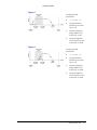
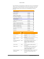
1
Parker Hannifin
User Information
Warning — ACR series products are used to control electrical and
mechanical components of motion control systems. You should
test your motion system for safety under all potential conditions.
Failure to do so can result in damage to equipment and/or serious
injury to personnel.
ACR series products and the information in this guide are the proprietary property
of Parker Hannifin Corporation or its licensers, and may not be copied, disclosed,
or used for any purpose not expressly authorized by the owner thereof.
Since Parker Hannifin constantly strives to improve all of its products, we reserve
the right to change this guide, and software and hardware mentioned therein, at
any time without notice.
In no event will the provider of the equipment be liable for any incidental,
consequential, or special damages of any kind or nature whatsoever, including
but not limited to lost profits arising from or in any way connected with the use of
the equipment or this guide.
© 2003-2007 Parker Hannifin Corporation
All Rights Reserved
Technical Assistance
Contact your local automation technology center (ATC) or distributor.
North America and Asia
Parker Hannifin
5500 Business Park Drive
Rohnert Park, CA 94928
Telephone: (800) 358-9070 or (707) 584-7558
Fax: (707) 584-3793
Email: [email protected]
Internet: http://www.parkermotion.com
Germany, Austria, Switzerland
Parker Hannifin
Postfach: 77607-1720
Robert-Bosch-Str. 22
D-77656 Offenburg
Telephone: +49 (0) 781 509-0
Fax: +49 (0) 781 509-176
Email: [email protected]
Internet: http://www.parker-emd.com
Europe (non-German speaking)
Parker Hannifin plc
Electromechanical Automation, Europe
Arena Business Centre
Holy Rood Close
Poole
Dorset, UK
BH17 7BA
Telephone: +44 (0) 1202 606300
Fax: +44 (0) 1202 606301
Email: [email protected]
Internet: http://www.parker-emd.com
Italy
Parker Hannifin
20092 Cinisello Balsamo
Milan, Italy via Gounod, 1
Telephone: +39 02 6601 2478
Fax: +39 02 6601 2808
Email: [email protected]
Internet: http://www.parker-emd.com
Technical Support E-mail
[email protected]
ii
Programmer’s Guide
Parker Hannifin
Table of Contents
User Information ......................................................ii
Table of Contents ....................................................iii
Change Summary ................................................... vii
Revision B Changes......................................................................................... vii
Getting Started .........................................................8
Application Description ..................................................................................... 8
Getting Started - Tutorial.................................................................................. 9
Starting a New Project................................................................................. 9
Configuring Axes ........................................................................................ 9
Configuring Masters .................................................................................. 12
Mapping Memory and Finishing the Application ............................................. 13
What has been generated? ........................................................................ 13
Creating a program................................................................................... 14
Running the Application ............................................................................. 15
Servo Tuning - Tutorial................................................................................... 16
Tuning Example........................................................................................ 17
System Configuration .............................................26
Communication Levels....................................................................................
System Level ...........................................................................................
Program/PLC Level....................................................................................
Hardware Configuration ..................................................................................
Defining Hardware Configuration ................................................................
Reviewing Your Configuration .....................................................................
Dedicated I/O................................................................................................
Input Assignment .....................................................................................
End-of-Travel Limits.......................................................................................
Hardware Limits .......................................................................................
Software Limits ........................................................................................
Attachments .................................................................................................
Software Attachments ...............................................................................
Master/Slave Attachments .........................................................................
Memory Allocations ........................................................................................
System and Program Memory Levels...........................................................
How Much Memory? ..................................................................................
Displaying Current Memory Allocations ........................................................
Displaying Free Memory ............................................................................
Deleting Programs and PLCs ......................................................................
Clearing Allocated Memory.........................................................................
26
26
27
28
28
28
29
29
30
30
31
33
33
35
39
40
41
42
42
42
42
Programming Basics...............................................43
Aliases .........................................................................................................
Program Labels .............................................................................................
Example ..................................................................................................
Remarks .......................................................................................................
Command Syntax ..........................................................................................
Description of Format ................................................................................
Arguments and Syntax ..............................................................................
Example Code Conventions .............................................................................
Programs and Commands ...............................................................................
Immediate Mode Commands ......................................................................
Adding Lines of Code to Programs...............................................................
Starting, Pausing, and Halting Programs ......................................................
Kill All Motion ................................................................................................
43
43
44
44
44
45
46
47
48
48
48
49
50
iii
Parker Hannifin
Program Flow ................................................................................................
Selection .................................................................................................
Repetition ................................................................................................
Other Conditional Statements.....................................................................
Parameters and Bits.......................................................................................
Using Parameters and Bits .........................................................................
A Word on Aliases.....................................................................................
Programming Example ..............................................................................
Parametric Evaluation ....................................................................................
Parentheses .............................................................................................
Examples.................................................................................................
51
51
54
55
56
57
58
59
60
61
61
Basic Setup.............................................................63
Before You Begin ...........................................................................................
Axis Limits ...............................................................................................
Character I/O ...........................................................................................
Drive Control............................................................................................
Feedback Control ......................................................................................
Global Objects..........................................................................................
Interpolation ............................................................................................
Logic Function ..........................................................................................
Memory Control........................................................................................
Non-Volatile .............................................................................................
Operating System .....................................................................................
Program Control .......................................................................................
Program Flow ...........................................................................................
Servo Control ...........................................................................................
Setpoint Control .......................................................................................
Transformation.........................................................................................
Velocity Profile .........................................................................................
Startup Programs ..........................................................................................
Resetting the Controller..................................................................................
Memory ........................................................................................................
Return to Factory Default................................................................................
Configuration ................................................................................................
A Note on the Jog/Home/Limits Dialog ........................................................
What is Configuration Code? ......................................................................
Resources Reserved for Generated Code......................................................
63
64
64
64
65
65
66
66
66
67
67
68
68
69
69
70
70
71
71
71
72
72
73
73
78
Making Motion ........................................................81
Four Basic Categories of Motion ....................................................................... 81
Move Types................................................................................................... 82
Absolute Motion........................................................................................ 82
Incremental Motion ................................................................................... 83
Comparing Absolute and Incremental Motion................................................ 83
Combining Types of Motion ........................................................................ 85
Immediate Mode ...................................................................................... 85
What are Motion Profiles? ............................................................................... 86
Interaction Between Motion Profilers ................................................................ 87
Primary Setpoint....................................................................................... 88
Velocity Profile Commands .............................................................................. 91
Velocity Profile Setup ................................................................................ 91
Feedback Control Commands ..................................................................... 92
Coordinated Moves Profiler.............................................................................. 96
Jog Profiler ................................................................................................... 99
JOG VEL Details.......................................................................................104
JOG Commands .......................................................................................105
Gear Profiler ................................................................................................109
Cam Profiler .................................................................................................110
Homing .......................................................................................................110
Homing Subroutines.................................................................................112
Limit Detection ........................................................................................118
Dedicated I/O for Homing .........................................................................118
iv
Programmer’s Guide
Parker Hannifin
Servo Loop Fundamentals ....................................120
Setpoint Compensation .................................................................................120
Viewing the Setpoint Calculations ..............................................................121
Following Error .............................................................................................121
Binary Host Interface ...........................................123
Binary Data Transfer .....................................................................................123
Control Character Prefixing .......................................................................123
High Bit Stripping ....................................................................................124
Binary Data Packets ......................................................................................125
Packet Request........................................................................................125
Group Code and Index .............................................................................125
Isolation Mask .........................................................................................125
Parameter Access ....................................................................................126
Packet Retrieval ......................................................................................126
Binary Parameter Access ...............................................................................127
Packet ID Codes ......................................................................................127
Usage Example........................................................................................128
Binary Get Long.......................................................................................128
Binary Set Long.......................................................................................128
Binary Get IEEE .......................................................................................129
Binary Set IEEE .......................................................................................129
Binary Peek Command ..................................................................................130
Binary Peek Packet ..................................................................................130
Binary Poke Command ..................................................................................131
Binary Poke Packet ..................................................................................131
Binary Address Command ..............................................................................132
Binary Address Packet ..............................................................................133
Binary Parameter Address Command ..............................................................134
Binary Address Packet ..............................................................................134
Usage Example........................................................................................134
Binary Mask Command ..................................................................................135
Binary Mask Packet ..................................................................................135
Usage Example........................................................................................135
Binary Parameter Mask Command ..................................................................136
Binary Mask Packet ..................................................................................136
Usage Example........................................................................................136
Binary Move Command..................................................................................137
Binary Move Packet..................................................................................137
Header Code 1 ........................................................................................139
Header Code 2 ........................................................................................139
Header Code 3 ........................................................................................139
Header Code 4 ........................................................................................140
Header Code 5 ........................................................................................140
Header Code 6 ........................................................................................140
Header Code 7 ........................................................................................141
Move Modes ............................................................................................141
Linear Moves...........................................................................................143
Arc Moves...............................................................................................143
NURB or SPLINE Moves ............................................................................144
Binary SET and CLR ......................................................................................144
Binary SET..............................................................................................144
Binary CLR..............................................................................................145
Usage Example........................................................................................145
Binary FOV Command ...................................................................................145
Binary Format .........................................................................................145
Binary ROV Command ...................................................................................147
Binary Format .........................................................................................147
Usage Example........................................................................................149
Application: Binary Global Parameter Access ....................................................149
Description .............................................................................................149
System Pointer Address (hardware dependent) ...........................................149
Reading Global Variables ..........................................................................149
Setting Global Variables............................................................................150
v
Parker Hannifin
Additional Features ..............................................151
CANopen .....................................................................................................151
Limited Amounts of Nodes and I/O.............................................................151
Alternate Mapping of Digital I/O ................................................................151
Semi-Automatic Network Configuration ......................................................152
AcroBASIC Language Access to CANopen I/O ..............................................155
Drive Talk ....................................................................................................164
Communication .......................................................................................165
Parameters and Bits.................................................................................165
Auto-Addressing ......................................................................................165
Drive Control Flags ..................................................................................166
Using Drive Talk ......................................................................................167
Closing Drive Talk ....................................................................................168
Using the “Pass Through” Mode .................................................................168
Inverse Kinematics .......................................................................................170
Programming the Inverse Kinematics .........................................................170
Troubleshooting ...................................................172
Problem Isolation..........................................................................................172
Information Collection ...................................................................................172
Troubleshooting Table ...................................................................................173
Error Handling ......................................................181
Sample Program (ACR90x0)......................................................................181
Appendix ..............................................................190
IP Addresses, Subnets, & Subnet Masks ..........................................................190
IP Addresses ...........................................................................................190
Subnets..................................................................................................192
Output Module Software Configuration Examples ..............................................195
Index....................................................................198
vi
Programmer’s Guide
Parker Hannifin
Change Summary
The change summary below lists the latest additions, changes, and
corrections to the ACR Programmer’s Guide and the corresponding
section of ACR-View Online Help.
Revision B Changes
Document 88-028698-01B (ACR Programmer’s Guide) supersedes
document 88-028698-01A. Changes associated with this document
are notated in this section.
Topic
Description
Program Labels
Refined the rules.
Command Syntax
Parentheses in Arguments and Syntax section:
use parentheses if a constant is signed or is
changing to a variable.
Example Code
New section.
Conventions
Startup Programs
Making Motion
Corrected example program.
Reorganized the Making Motion chapter. Added
REN and RES details for Velocity Profile
Commands section. Changed the term in section
titles from “Commanding Motion” to “Move Types.”
Jog Profiler
Added Jog Profiler section to Making Motion
chapter.
Error Handling
Revised and reformatted sample error handling
program.
vii
Parker Hannifin
Getting Started
Use the tutorials in this section to guide you through the
configuration and tuning of your ACR series controller, and to help
you create a project and become familiar with the ACR-View
software.
Application Description
The tutorial leads you through setting up a sample application—a
three-axis system (an X-Y-Z gantry that moves a camera carriage)
controlled by a four-axis, standard ACR9000.
Axis 0—the X axis
Axis 1—the Y axis
Axis 2—the Z axis
Each axis uses a Parker BE341HQ motor powered by an Aries Drive,
and is leadscrew driven with a pitch of 5 rev/inch. In addition, the
application requires inputs 0-5 for hardware limit switches. The X and
Y axes have a maximum of 24 inch of travel; The Z axis has a
maximum of 6 inch of travel.
The I/O is as follows:
Output34 = Camera
Input 0 = X axis Positive Hardware Limit Switch
Input 1 = X axis Negative Hardware Limit Switch
Input 2 = Y axis Positive Hardware Limit Switch
Input 3 = Y axis Negative Hardware Limit Switch
Input 4 = Z axis Positive Hardware Limit Switch
Input 5 = Z axis Negative Hardware Limit Switch
Special Requirement: There is an area designated by a light curtain
connected to input 10, where the gantry cannot move to unless the
camera carriage is retracted (Z-axis at 5 inches). In normal
operations, the camera will not go into that area, but for safety
reasons, the Z-axis must retract if it crosses the light curtain. This is the
sole purpose of the Z-axis.
8
Programmer’s Guide
Parker Hannifin
Getting Started - Tutorial
Use this basic tutorial to familiarize yourself with the ACR-View
software and how to set up a project.
Starting a New Project
When you create a new project, wizards guide you as you set up the
project. First, add a controller and provide its basic configuration
data.
1.
On the Start menu click Programs, click Parker Automation,
then click ACR-View, and then select ACR-View.
2.
Click Create New Project, and then type Sample in the box.
Click OK.
3.
Click ACR9000, and then click Next.
4.
Do the following:
5.
a.
In the Configuration list, click P0.
b.
In the Number of Axes list, click U4.
c.
In the Option list, click M0 or B0.
d.
Then click Next.
Click Finish.
Once you have added a controller, ACR-View asks you to specify
the type of communications you are using with the controller.
For this exercise, it is not necessary to specify a communications
protocol. Instead, close the window.
Configuring Axes
The Project Workspace—found on the left side of the ACR-View
window—uses a tree structure to organize your project. Notice that
the Sample project appears at the top and below it is the ACR9000
controller you just added. Next, use the Configuration Wizard to set
up each axis.
Axis 0
6.
In the Project Workspace, click Configuration Wizard.
7.
Under Configuration Wizard, click Axis 0.
8.
In the Axis 0 dialog box, do the following:
9.
a.
In the Axis Name (Alias) box, type X
b.
In the Command Output list select DAC 0.
c.
Click Next.
In the Drive/Motor dialog, click Next.
10. In the Feedback dialog, click Next.
Getting Started 9
Parker Hannifin
11. In the Scaling dialog, do the following:
a.
Under Specify Units, click Inches.
b.
In the Transmission list, select Leadscrew.
c.
In the Transmission Details box (below the Transmission
list), type 0.2—this represents the number of inches per
revolution of the leadscrew.
d.
Click Next.
12. In the Fault dialog, do the following:
a.
Select the Enable Positive Software Limit Detection check
box, and then type 24
b.
Select the Enable Negative Software Limit Detection
check box, and then type 0
c.
Select the Enable Maximum Position Error Detection
check box.
d.
In the Maximum Positive Position Error box, type 0.2
e.
In the Maximum Negative Position Error box, type –0.2
f.
Click Next.
13. In the Dedicated I/O dialog, do the following:
a.
In the Input Type list, select Onboard Input 0 and then
click Positive Limit.
b.
In the Input Type list, select Onboard Input 1 and then
click Negative Limit.
c.
Click Next.
Axis 1
14. In the Project Workspace, click Axis 1.
15. In the Axis 1 dialog box, do the following:
a.
In the Axis Name (Alias) box, type Y
b.
In the Command Output list select DAC 1.
c.
Click Next.
16. In the Drive/Motor dialog, click Next.
17. In the Feedback dialog, click Next.
18. In the Scaling dialog, do the following:
10
a.
Under Specify Units, click Inches.
b.
In the Transmission list, select Leadscrew
c.
In the Transmission Details box (below the Transmission
list), type 0.2—this represents the number of inches per
revolution of the leadscrew.
d.
Click Next.
Programmer’s Guide
Parker Hannifin
19. In the Fault dialog, do the following:
a.
Select the Enable Positive Software Limit Detection check
box, and then type 24
b.
Select the Enable Negative Software Limit Detection
check box, and then type 0
c.
Select the Enable Maximum Position Error Detection
check box.
d.
In the Maximum Positive Position Error box, type 0.2
e.
In the Maximum Negative Position Error box, type –0.2
f.
Click Next.
20. In the Dedicated I/O dialog, do the following:
a.
In the Input Type list, select Onboard Input 2 and then
click Positive Limit.
b.
In the Input Type list, select Onboard Input 3 and then
click Negative Limit.
c.
Click Next.
Axis 2
21. In the Axis 2 dialog box, do the following:
a.
In the Axis Name (Alias) box, type Z
b.
In the Command Output list select DAC 2.
c.
Click Next.
22. In the Drive/Motor dialog, click Next.
23. In the Feedback dialog, click Next.
24. In the Scaling dialog, do the following:
a.
Under Specify Units, click Inches.
b.
In the Transmission list, select Leadscrew
c.
In the Transmission Details box (below the Transmission
list), type 0.2—This represents the number of inches per
revolution of the leadscrew.
d.
Click Next.
Getting Started 11
Parker Hannifin
25. In the Fault dialog, do the following:
a.
Select the Enable Positive Software Limit Detection check
box, and then type 6
b.
Select the Enable Negative Software Limit Detection
check box, and then type 0
c.
Select the Enable Maximum Position Error Detection
check box.
d.
In the Maximum Positive Position Error box, type 0.2
e.
In the Maximum Negative Position Error box, type –0.2
f.
Click Next.
26. In the Dedicated I/O dialog, do the following:
a.
In the Input Type list, select Onboard Input 4 and then
click Positive Limit.
b.
In the Input Type list, select Onboard Input 5 and then
click Negative Limit.
c.
Click Next.
Axis 3
27. In the Axis 3 dialog box, do the following:
a.
In the Command Output list, click Not Used.
b.
Click Next.
Configuring Masters
A master calculates trajectory and generates motion. You can
assign one or more axes to a master. Each master only performs
tasks for the axes assigned to it. In this sample application, the X and
Y axes operate a gantry system.
The motions of axes X and Y must be coordinated to make the
compound motion, so these axes are assigned to the same master.
Whereas the Z axis motion is not coordinated with other axes, so is
assigned to its own master.
Having assigned axes to their respective masters, you then define
the motion profile for each master (acceleration and deceleration
ramps, and velocity).
1.
12
In the Masters dialog, assign axes X and Y to master 0:
a.
In the Axes list to the left, select Axis 0 and Axis 1.
b.
In the Masters list to the right, select Master 0.
c.
Click Move Axes to Master.
d.
Click Next.
Programmer’s Guide
Parker Hannifin
2.
3.
4.
In the Masters dialog, assign axis Z to master 1:
a.
In the Axes list to the left, select Axis 2.
b.
In the Masters list to the right, select Master 1.
c.
Click Move Axes to Master.
d.
Click Next
In the Master 0 dialog, do the following:
a.
In the Acceleration Ramp box, type 10
b.
In the Velocity box, type 5
c.
In the Deceleration Ramp box, type 10
d.
In the Stop Ramp box, type 10
e.
Click Next.
In the Master 1 dialog, do the following:
a.
In the Acceleration Ramp box, type 20
b.
In the Velocity box, type 10
c.
In the Deceleration Ramp box, type 20
d.
In the Stop Ramp box, type 20
e.
Click Next.
Mapping Memory and Finishing the Application
The memory mapping allows you to control how much memory is
dedicated to specific items: programs, PLC programs, global
Variables, and Defines. Most programs do not require special
memory mapping.
The final step is to review the configuration of your controller, its
masters, and axes. Once you have completed the Configuration
Wizard, the Finish dialog lists any configuration errors or warnings. To
review the item, double-click it and the wizard takes you to the
appropriate dialog to make any necessary corrections. You can also
view a report, detailing the setup of the controller.
1.
In the Memory dialog, click Next.
2.
In the Finish dialog, you can correct any warnings or errors
displayed. Click Finish
What has been generated?
Once finished, you can review the code generated by the
Configuration Wizard. The Configuration Wizard led you through the
process of setting up the controller and its axes—assigning drive and
motor combinations to each axis; assigning feedback, scaling, fault
detection, and dedicated I/O to each axis; assigning axes to
masters, and defining master motion-profiles. The wizard created
code in PLC program 5 for latching conditions of the hardware limits,
and in Program 7 for software limits, hardware limits, and maximum
position error.
Getting Started 13
Parker Hannifin
Creating a program
This application requires two programs.
Program 0: Determines the motion the gantry (axes X and Y),
allowing a camera to take scans from various positions.
Program 1: Activates when the gantry (axes X and Y) crosses a
boundary marked by a light curtain. When the gantry passes
through the light curtain, input 10 turns on, which initiates retraction
of the camera (axis Z) to a safety position. When input 10 turns off,
the camera returns to its original position.
1.
In the Project Workspace, select Program Editor. By default, it
opens Program 0.
2.
In the Program Editor window under the comment 'TODO: edit
your program here, type the following (or copy and paste the
code to the program editor):
DRIVE ON X
X0 Y0
DWL 5
_Head
X6 Y6
SET 34
DWL 5
CLR 34
X12 Y6
SET 34
DWL 5
CLR 34
X18 Y6
SET 34
DWL 5
CLR 34
X18 Y12
SET 34
DWL 5
CLR 34
X12 Y12
SET 34
DWL 5
CLR 34
X6 Y12
SET 34
DWL 5
CLR 34
GOTO Head
3.
14
Y
: REM Enable X and Y Axes
: REM Return X and Y axes to Zero Position
: REM Wait 5 seconds (for Camera Process to finish)
:
:
:
:
:
:
:
:
:
:
:
:
:
:
:
:
:
:
:
:
:
:
:
:
:
REM
REM
REM
REM
REM
REM
REM
REM
REM
REM
REM
REM
REM
REM
REM
REM
REM
REM
REM
REM
REM
REM
REM
REM
REM
Move to Position 1
Turn on OUTPUT 34 (Camera Process)
Wait 5 seconds (for Camera Process to
Turn off OUTPUT 34 (Camera Process)
Move to Position 2
Turn on OUTPUT 34 (Camera Process)
Wait 5 seconds (for Camera Process to
Turn off OUTPUT 34 (Camera Process)
Move to Position 3
Turn on OUTPUT 34 (Camera Process)
Wait 5 seconds (for Camera Process to
Turn off OUTPUT 34 (Camera Process)
Move to Position 4
Turn on OUTPUT 34 (Camera Process)
Wait 5 seconds (for Camera Process to
Turn off OUTPUT 34 (Camera Process)
Move to Position 5
Turn on OUTPUT 34 (Camera Process)
Wait 5 seconds (for Camera Process to
Turn off OUTPUT 34 (Camera Process)
Move to Position 6
Turn on OUTPUT 34 (Camera Process)
Wait 5 seconds (for Camera Process to
Turn off OUTPUT 34 (Camera Process)
Start Cycle over again
In the Project Workspace, select Program 1.
Programmer’s Guide
finish)
finish)
finish)
finish)
finish)
finish)
Parker Hannifin
4.
In the Program Editor window under the comment 'TODO: edit
your program here, type the following (or copy and paste the
code to the program editor):
DRIVE ON Z
Z0
: REM
_Safe
: REM
WHILE (BIT10=0)
WEND
: REM
Z5
: REM
WHILE(BIT10=-1)
WEND
: REM
Z0
: REM
GOTO Safe : REM
: REM Enable Z Axis
Return Z Axis to Zero Position
Just a marker label
: REM Wait for Input 10 to be activated = -1
Gantry in Danger Zone
Retract Carriage to Safe Position
: REM Wait for gantry to move out of danger zone
Input 10 back to normal state = 0
Extend carriage down
Go back to marker to wait for next danger zone
Running the Application
You’ve configured your controller, drives, and motors. And you’ve
created the necessary programs for the application. The application
hardware is set up, and the servo motors are already tuned. You are
ready to run the application.
1.
2.
In the Project Workspace, click Terminal Emulator.
In the Terminal Emulator window type:
PROG 0
RUN
PROG 1
RUN
Getting Started 15
Parker Hannifin
Servo Tuning - Tutorial
The tuning process lets you hone the servo response and settling for
your particular system.
Settling and responsiveness are the main components that
determine performance. Generally, the goal of servo tuning is good
settling, with a secondary goal of good responsiveness. Ultimately,
only you can determine which aspect is of prime importance, and
when the tuning is “good enough” for your system.
For safety, tune the servo system unloaded. Once the servo is stable
and responsive, then add the load and tune the servo again.
NOTE: Because the differences between systems are wide, the
following are provided only as guidelines.
Proportional and derivative gains work against each other—an
increase to one gain affects the other. With this in mind, treat tuning
as an iterative process: alternate between adjusting proportional
and derivative gains.
•
PGAIN: Adjusts servo response. You can always try to increase
responsiveness, though mechanics ultimately limit response
time.
•
DGAIN: Adjusts settling time. The goal is always good settling.
•
IGAIN: Adjusts steady-state errors (not discussed in this tutorial).
Adding integral gain also increases responsiveness, though the
increase might not be noticeable.
Warning — When tuning a servo motor, remove all loads from
the motor to prevent personal injury or mechanical
destruction. Once tuning provides a stable and responsive
servo motor, you can attach the load and start the tuning
process again.
16
Programmer’s Guide
Parker Hannifin
Tuning Example
The tuning example assumes the following:
•
Parker BE 241 motor.
•
9 to 1 load-to-rotor inertia ratio.
Illustration Legend
Color
Position
Green
Commanded
Yellow
Actual
1.
As a starting point, the PGAIN is set to 0.0003; no DGAIN is set
at this time. Figure 1 shows that the motor is under responsive.
Getting Started 17
Parker Hannifin
2.
The PGAIN is increased to 0.0005 to increase the response. As
Figure 2 illustrates, the motor response increased significantly,
the motor is under-damped.
Before we continue adjusting the motor response, it is
important to compensate for the under-damping by adding
DGAIN.
18
Programmer’s Guide
Parker Hannifin
3.
Setting the DGAIN to 0.00001 slightly over-damps the response,
as shown in Figure 3. Now we can turn again to adjusting the
motor response by increasing the PGAIN.
If we were to increase the proportional gain without adjusting
the derivative gain, the oscillations would increase and
possibly create motor instability.
Getting Started 19
Parker Hannifin
4.
20
With PGAIN increased to 0.001, motor responsiveness has
increased (Figure 4) and the over-damping has decreased
slightly. As there is no significant change to the settling, there is
no need to adjust the DGAIN. However, there is still room for
improvement on motor response.
Programmer’s Guide
Parker Hannifin
5.
The PGAIN is increased to 0.005, resulting again in increased
responsiveness (Figure 5). But with increased oscillations, due
to under-damping, we need to adjust the DGAIN again.
Getting Started 21
Parker Hannifin
6.
22
Increasing the DGAIN to 0.00003 damps the oscillation. As
Figure 6 illustrates, both motor response and damping look
good. We are ready to add a load to the motor.
Programmer’s Guide
Parker Hannifin
7.
With a loaded motor, we can see that the response has slowed
and the damping is weaker. Like before, we can increase the
PGAIN for a better response.
Getting Started 23
Parker Hannifin
8.
24
The PGAIN is increased to 0.02, and we can see better
response from the motor. But there is still some oscillation from
the motor, so we increase the damping.
Programmer’s Guide
Parker Hannifin
9.
With DGAIN increased to 0.00015 the chattering is significantly
reduced—both motor response and damping look good.
With a load attached, the motor is now fast and stable; no
more tuning is necessary.
Getting Started 25
Parker Hannifin
System Configuration
The following section helps you understand how to configure your
ACR controller for use.
•
Communication Levels
•
Hardware Configuration
•
Dedicated I/O
•
End-of-Travel Limits
•
Attachments
•
Memory Allocations
Communication Levels
Communication channels are either at the "system" level or at a
"program" level. The command prompt indicates which level a
communication channel is currently at.
Certain commands are limited to a specific level. To determine at
which levels a command might be used, refer to the Prompt Level in
the command description.
System Level
The "system" level is where a communication channel is at after
power-up. The command prompt at this level is as follows:
The set of commands you can issue from the system level is limited.
You can return to the system level from any other level by issuing the
SYS command.
26
Programmer’s Guide
Parker Hannifin
Program/PLC Level
The "program" or “PLC” level lets you edit and run individual
programs or PLCs. The command prompt at the program level is as
follows:
Pnn>
The command prompt at the PLC level is as follows:
PLCn>
Where "nn" or “n” represents the currently active program number.
To select the program or PLC level from any other level, issue the
PROG or PLC command followed by the program number. For
example, the following selects program number 1 no matter which
level or program is active:
•
To go back to the system level from the program or PLC level,
issue the SYS command.
•
To move between programs, issue the PROG or PLC command
followed by the desired program or PLC number.
The following figure shows the various communication channel
levels. The communication channels on the left can all be active at
the same time and be operating at different levels. For example,
"COM1:" could be editing program number 3, while "COM2:"
monitors user variables being modified by program number 5.
System Configuration 27
Parker Hannifin
Hardware Configuration
Before using an ACR controller, you must define for the firmware
what specific hardware is installed. The default configuration is as
follows:
CONFIG ENC8 DAC4 DAC4 ADC8
The command uses four arguments— encoders, module 0, module 1,
and module 2.
Encoder: The encoder argument is the number of encoder channels
installed.
NONE, ENC2, ENC4, ENC6, ENC8, ENC10
Module 0: The module 0 argument is the type of module installed in
the first SIMM socket.
NONE, DAC2, DAC4, STEPPER2, STEPPER4, DACSTEP2, DACSTEP4
Module 1: The module 1 argument is the type of module installed in
the second SIMM socket.
NONE, DAC2, DAC4, STEPPER2, STEPPER4
Module 2: The module 2 argument is indicates whether an ADC
module is installed in the third SIMM socket.
NONE, ADC8
In ACR-View, the New Controller Wizard determines the CONFIG
statement for you.
Defining Hardware Configuration
► To define the hardware, use the CONFIG command.
Reviewing Your Configuration
► To view the current configuration, enter CONFIG with no
arguments.
28
Programmer’s Guide
Parker Hannifin
Dedicated I/O
The ACR series controller contains I/O dedicated to Drive Enable,
Drive Reset, and Drive Fault signals. Refer to the appropriate
hardware manual for configuration.
The ACR series controllers also contain hardware and software endof-travel limits, and homing. In the ACR90x0, the default is the lowest
onboard inputs being assigned to the lowest axis. For example, axis 0
uses inputs 0, 1, and 2; axis 1 uses inputs 3, 4, and 5.
Input Assignment
For each axis, you can assign which inputs are used for positive and
negative hardware limits, and the input used for homing. The default
is that the lowest onboard inputs are assigned to the lowest axis—
axis 0 uses inputs 0, 1, and 2; axis 1 uses inputs 3, 4, and 5; and so on.
The Configuration Wizard can perform the setup for you, or you can
use the HLBIT command to assign the inputs manually (no
corresponding parameter exists).
The value you provide sets the input to use for the positive hardware
limit. The controller then sets the next contiguous input for the
negative hardware limit, and the next contiguous input is set for
homing.
For example, you want to assign input three as the positive
hardware limit for axis Y. The command HLBIT Y3 is sent; as a result,
input 3 becomes the positive hardware limit, input 4 becomes the
negative hardware limit, and input 5 becomes the homing input.
System Configuration 29
Parker Hannifin
NOTE: There are no restrictions regarding how to assign hardware
limits and homing inputs. However, you should exercise
caution because it is possible to create imaginary limit and
home inputs. This is because the controller assumes all three
inputs are in the same multiple of 32 bits. The assignment of
inputs does not roll over to the next block of 32 bits. For
example, if the positive hardware limit is assigned to input
31, the negative hardware limit and homing inputs are not
assigned. Instead, they become imaginary inputs with a
value of zero.
End-of-Travel Limits
The ACR series controller can respond to hardware and software
end-of-travel limits, which prevent a motor’s load from traveling past
defined limits. You can use hardware and software limits regardless
of incremental or absolute positioning.
Software and hardware limits, typically, are positioned so that when
the load reaches the software limit, the motor/load starts
decelerating towards the hardware limit. This provides a smoother,
more graceful stop towards the hardware limit than if the hardware
limit, itself, were activated.
When a load reaches an end-of-travel limit (hardware or software),
the ACR controller stops the master and all attached axes. The stop
is made using the hardware or software deceleration rate—HLDEC or
SLDEC, respectively.
Hardware Limits
For each axis, you can set a pair of inputs to act as positive and
negative limits for hardware travel. Parameters 4600-4615 provide
Control and Status bits for software limits. You can enable the
individual positive and negative limits and set the active level for
each, as well as check the current and previous states of the limits.
NOTE: When a hardware limit is a hit, the KAMR (Kill All Motion
Request) Bit is also set. Before motion can resume, you must
clear the KAMR Bits for the affected master and its attached
axes.
30
Programmer’s Guide
Parker Hannifin
Hardware Limit Enable
By default, positive and negative hardware limits are disabled. You
can enable the limits by setting the appropriate control bits (bit 20=
positive hardware limit enable, bit 21= negative hardware limit
enable). You can also control the hardware limits using the HLIM
command.
HLIM Hardware Limits
Value
Description
0
Disables positive limit and negative limit
(default)
1
Enables positive limit and disables
negative limit
2
Disables positive limit and enables
negative limit
3
Enables positive limit and negative limit
In the Configuration Wizard, you can enable hardware limits in the
Faults dialog.
Software Limits
For each axis, you can set a pair of absolute positions that act as
software-based limits. Between these limits, unlimited motion can
occur. If a software limit is crossed, the controller stops motion for
that axis, its master, and attached axes.
Parameters 4600-4615 provide Control and Status bits for software
limits. You can enable the individual positive and negative limits, as
well as check the current and previous states of the limits.
NOTE: Software limits do not use the Kill All Motion Request (KAMR)
bits. Therefore, you can resume motion in the opposite
direction of the software limit. For example, if the
application encounters a positive software limit and stops,
the application can resume motion in the negative
direction.
System Configuration 31
Parker Hannifin
Soft Limit Enable
By default, positive and negative software limits are disabled. You
can enable the limits by setting the appropriate control bits (bit 22=
positive software limit enable, bit 23= negative software limit
enable). You can also control the software limits using the SLIM
command.
SLIM Software Limits
Value
0
Description
Disables positive limit and negative limit
(default)
1
Enables positive limit and disables
negative limit
2
Disables positive limit and enables
negative limit
3
Enables positive limit and negative limit
In the Configuration Wizard, you can enable hardware limits in the
Faults dialog.
Software Limit Positions
You cans specify the positions for software limits using the SLM
command.
32
Programmer’s Guide
Parker Hannifin
Attachments
Attachments are a means of defining the hardware you have, and
how it connects together.
Software Attachments
Before using an ACR controller, define the feedback and signal
output for each axis. By default, each axis is attached to its
matching encoder and DAC output. Using the ATTACH AXIS
command, change the default attachments to fit your application.
By default, each encoder and DAC is set to the same index as the
axis to which it is attached. The default axis attachments are as
follows:
ATTACH AXIS0 ENC0 DAC0 ENC0
ATTACH AXIS1 ENC1 DAC1 ENC1
ATTACH AXIS2 ENC2 DAC2 ENC2
ATTACH AXIS3 ENC3 DAC3 ENC3
ATTACH AXIS4 ENC4 DAC4 ENC4
ATTACH AXIS5 ENC5 DAC5 ENC5
ATTACH AXIS6 ENC6 DAC6 ENC6
ATTACH AXIS7 ENC7 DAC7 ENC7
The ATTACH AXIS command has four arguments—axis, position,
signal, and velocity.
Axis: The axis argument determines to which axis you are making the
attachments.
AXIS0 through AXIS7
Position: The position argument determines what position feedback
is attached to the axis. You can use the following:
•
Quadrature encoder feedback applied to the ACR controller’s
encoder inputs.
ENC0 through ENC7
•
Analog position feedback applied to the ACR controller’s
analog inputs.
ADC0 through ADC7
•
Open loop stepper feedback.
STEPPER0 through STEPPER7
System Configuration 33
Parker Hannifin
Signal: The signal argument determines the signal output by the ACR
controller.
• Analog voltage output
DAC0 through DAC7
• Step and directions outputs.
STEPPER0 through STEPPER7
• Sinusoidal/Trapezoidal commutation output.
CMT0 through CMT7
Velocity: The velocity argument determines the velocity
attachment. This lets you set a velocity feedback source for dualloop feedback—this provides a software tachometer based on
encoder or analog signal input.
NOTE: If you are using single-loop feedback, set the velocity
argument to the same value used in the position argument.
•
Quadrature encoder feedback applied to the ACR controller
encoder inputs.
ENC0 through ENC7
•
Analog position feedback applied to the ACR Card controller
inputs.
ADC0 through ADC7
Attaching Axes
By default, each encoder and DAC is set to the same index as the
axis to which it is attached (for example, ATTACH AXIS0 ENC0 DAC0
ENC0). It is good programming practice to use the same index for
the feedback or signal output as the axis to which you are
attaching.
For example, to attach ADC 4 as position feedback, and DAC 4 as
the command signal to axis 4, send the following:
ATTACH AXIS4 ADC4 DAC4 ADC4
There is one exception—dual-loop feedback. With dual-loop
feedback, you can attach a second feedback source to an axis. In
this case, you must indicate which additional encoder is being used.
For example, to attach encoder 4 as position feedback, DAC 4 as
the command signal, and encoder 9 as the velocity feedback, send
the following:
ATTACH AXIS4 ENC4 DAC4 ENC9
34
Programmer’s Guide
Parker Hannifin
Master/Slave Attachments
Without master/slave attachments, motion cannot occur. So what
are masters and slaves?
NOTE: There are no default master/slave attachments.
Masters
Master are trajectory (or motion profile) generators for coordinated
motion. A master computes trajectories only for the slave or slaves
attached to that master. You can assign only one master to a
program.
The number of masters available is governed by the number of
programs available on each controller:
• ACR1505 has 16 masters.
• ACR8020 has 16 masters.
•
ACR9000 has eight masters.
Attaching Masters
For a program to make motion, it must have a master and slaves
attached to it. Use the ATTACH MASTER command to designate
which trajectory generator to use with a program. When attaching
masters, observe the following:
•
Place the ATTACH commands in the declarations above a
program.
•
You can attach a specific master to only one program. You
cannot use the same master in multiple programs.
•
Use ATTACH MASTER before the ATTACH SLAVE command—you
first have to assign a master to a program, then you can
attach slaves to the master.
NOTE: While you can attach any master to any program, it is
important to be consistent across programs and
applications.
For example, you might always use program zero for managing
communications, and program one for motion with master zero
attached. As another example, the ACR-View software uses the
same index for the master as the program to which it is being
attached (master zero attaches to program zero, master one
attaches to program one, etc.).
Setting up an application with independent axes is straightforward.
For example, a four-axis ACR9000 controls four independent axes;
you attach master and slave zero to program zero, master and slave
one to program one, and so forth. Each program uses a separate
master for each slave.
System Configuration 35
Parker Hannifin
Setting up coordinated motion does not differ. After attaching a
master to the program, you attach all the slaves. For example, an
ACR9000 controls coordinated motion for five axes: you attach
master zero to program zero, and axes zero through four to program
zero.
For more information, see the ATTACH MASTER command in the ACR
Command Language Reference.
Slaves
Each master uses its own set of dedicated slaves; slaves act as
simple placeholders for axes. By attaching an axis to a slave, you
are connecting the axis to a specific master.
You can attach one axis to one slave, and subsequently it is
attached to one master. The total number of slaves available differs
between controllers:
•
ACR1505 has 16 slaves.
•
ACR8020 has 16 slaves.
•
ACR9000 has 8 slaves.
•
ACR9030 has 16 slaves.
•
ACR9040 has 16 slaves.
NOTE: You cannot assign an axis to more than one slave and
master. If necessary, you can disconnect the axis from its
master and attach it to a different master. For more
information, see the DETACH command.
36
Programmer’s Guide
Parker Hannifin
The diagram below helps illustrate the concepts and relationships
between masters and slave, programs and axes.
Attaching Slaves
As previously stated, for a program to make motion, it must have a
master and slaves attached to it. Once you have attached a
master, you can then attach the slaves. Each master contains its
own set of slaves, and each set of slaves is independent of the
slaves in other masters. When attaching to slaves, start with the first
available slave.
Use the ATTACH SLAVE command to designate which axis you are
attaching to a slave. When attaching slaves, observe the following:
•
You can attach as many slaves to a master as there are axes
available.
•
You attach one axis to one slave. Therefore, that axis is
attached to only one master.
•
You cannot assign an axis to different slaves in a single master,
or to different masters.
System Configuration 37
Parker Hannifin
•
To reuse an axis and attach it to a different master/slave, you
must first separate it from the current master/slave using the
DETACH command.
For more information, see the ATTACH SLAVE command in the ACR
Command Language Reference.
Slaves and Axis Names
The ATTACH SLAVE command lets you provide an axis name (up to
four alpha characters)—such as X, ARM, or UP. You can use the axis
name in the program code (for that program only). The axis name
provides meaning to the axis, making code more readable and
easier to troubleshoot.
The ACR controller recognizes the axis name only in the program
where it is declared. For example, in program zero you give axes
zero and one the names ARM and UP, respectively. Other programs
do not recognize the axis names ARM and UP.
While you cannot use the axis names in other programs, you can
access those axes using their system names—AXIS0 and AXIS1.
NOTE: Do not use the characters P or F as an axis name. P is
reserved for global and system parameters; F is reserved for
the F (feedrate) command.
Example
In the following example, program zero controls a two-axis machine.
Axis zero is given the axis name X, and axis one is given the axis
name Y.
PROG0
HALT
DETACH
ATTACH MASTER0
ATTACH SLAVE0 AXIS0 “X”
ATTACH SLAVE1 AXIS1 “Y”
38
Programmer’s Guide
Parker Hannifin
Memory Allocations
Memory allocation on the ACR series controllers is completely
customizable —you can assign controller memory to features and
functions that need it most for your particular application. Using the
Configuration Wizard, you can quickly allocate memory for the
following: programs, PLCs, global variables, local variables, arrays,
and communication stream buffers.
It is important to dimension the memory correctly for your
application. The factory default memory allocations are limited to
programs, which receive 512K. The communication stream buffers
receive 256 bytes each.
Once you have allocated memory for a program, PLC, or global
variables, you cannot change it without first clearing the memory
space (CLEAR command). Otherwise, you receive a “Redimensioned block” error.
NOTE: The controller stores system memory in battery-backed
SRAM, as well as hardware configuration data. If you reset
memory using the BRESET command, memory allocation
returns to factory settings.
Caution — When you send the BRESET command, you cannot
return the battery to normal operation without removing and
then restoring power. Stored programs are lost during the power
restore.
System Configuration 39
Parker Hannifin
NOTE: The memory organization differs for each controller—for
more information, see the section titled Memory
Organization in the ACR Command Language Reference.
System and Program Memory Levels
Memory is allocated at two levels, the system level and program
level:
System
At the SYS prompt, you can allocate memory for the following:
•
Programs: The factory default divides memory equally among
programs 0-7 (factory default is 512K total).
•
PLC Programs: The factory default provides no memory
allocated to PLC programs.
•
Communication Stream Buffers: The stream buffers are
optimized for communication (factory default is 256 bytes).
Most applications do not require adjustments to the buffer size,
as the controllers use flow control.
If you are losing data, you can adjust the stream buffer. As
each application is different, incrementally increase the buffer
size to determine the best setting for your application.
Increasing the buffer allows the front-end software to perform
smoothly while the controller manages data in the
background.
•
Global Variables: The factory default provides no memory
allocated to global variables. There are 4096 user parameters
available (64-bit floating point); the range is P0-P4096. For
example, if you dimension memory for 100 global variables,
then you can use P0-P99.
•
Aliases: The factory default provides no memory allocated to
aliases. Once you define the number of aliases, you can use
the #DEFINE command to set them up.
Program
At the PROG prompt, you can allocate memory for the following:
40
•
Local Variables: The factory default provides no memory
allocated to local variables. After allocating memory, these
items are available only within the specified program.
•
Strings: The factory default provides no memory allocated to
strings. After allocating memory, these items are available only
within the specified program.
Programmer’s Guide
Parker Hannifin
•
Arrays: The factory default provides no memory allocated to
arrays. After allocating memory, these items are available only
within the specified program.
How Much Memory?
There are no simple guidelines to determine how much memory your
programs might require; the needs of each application are different.
It also depends how you intend to develop programs for the
controller.
If you just sit down and begin writing code through the ACR-View
software, consider allocating more memory than you think you
might need. As you get closer to completion, you can scale back
the memory allocations as appropriate.
You can also write the programs first, determine how much memory
it uses, and dimension what is necessary.
The following table shows memory usage by various data and
program structures. Use it to help determine how much memory is
needed for each program:
Data/Program Structure
Memory Usage
LV variables
4 bytes per element (32-bit integers)
SV variables
4 bytes per element (32-bit floating point)
DV variables
8 bytes per element (64-bit floating point)
$V variables
4 bytes + 1 byte per character
Array references
4 bytes per array reference + 4 bytes
LA arrays
4 bytes per element + 4 bytes
SA arrays
4 bytes per element + 4 bytes
DA arrays
8 bytes per element + 4 bytes
$A arrays
1 byte per character
Commands
4 bytes per command
Parametric Statements
4 bytes per operator
Long Constants
4 bytes per constant (32-bit integer)
Single Constants
4 bytes per constant (32-bit floating point)
Double Constants
8 bytes per constant (64-bit floating point)
String Constants
4 bytes + 1 byte per character
Subroutine Calls
4 bytes per level
Aliases (#DEFINE)
48 bytes per define + 16 bytes
Move Buffer (MBUF)
136 bytes per move
System Configuration 41
Parker Hannifin
Displaying Current Memory Allocations
From the SYS prompt, you can view memory allocations for
programs, PLCs, communication stream buffers, global variables,
and aliases. The controller displays the default memory allocation for
only programs. For all other items, you must allocate memory to
them (PLCs, global variables, and aliases), or change the default
memory allocation (communication stream buffers).
From the PROG prompt, you can view the memory allocations for
local variables, strings, and arrays.
► To view current memory allocations, use the DIM command.
Displaying Free Memory
You can view the free memory for the system or a specific program
or PLC. For more information, see the MEM command in the ACR
Command Language Reference.
► To view free memory, use the MEM command.
Deleting Programs and PLCs
Before you can clear memory allocation for programs or PLCs, you
must erase the program or PLC program being stored. You can
delete all programs or a specific program or PLC. For more
information, see the NEW command in the ACR User’s Guide.
► To erase all programs and PLCs, use the NEW ALL command.
Clearing Allocated Memory
You can clear memory at the system or program level, returning the
controller to factory set memory allocations.
NOTE: The CLEAR command behaves differently at the system and
program levels. For more information, see the CLEAR
command in the ACR Command Language Reference.
► To free the allocated memory, use the CLEAR command.
42
Programmer’s Guide
Parker Hannifin
Programming Basics
The following section explains some fundamental concepts of the
AcroBASIC programming language.
Aliases
Alternative names, called aliases, can be assigned to parameters,
bits, constants, and variables to make program code more
readable. Aliases are recognized globally (across user programs).
NOTE: Do not confuse aliases with axis names. You can assign an
axis name to an axis through the ATTACH SLAVE command.
Observe the following rules when creating and using aliases:
•
Use a maximum of 24 letters.
•
Aliases are case sensitive.
•
Do not use numbers, spaces, or special characters (such as _
and @).
•
Use caution when using aliases with local variables.
An alias is recognized across programs, while local variables
are limited to the program in which they are created. This can
cause problems if you have created similar local variables in
different programs. For example, if long variables are
dimensioned in three programs, then the alias “counter” is
assigned to LV1 (long variable 1), the controller recognizes
“counter” as an alias in all three programs, though it represents
a counter in only one program.
For more information, see the #DEFINE command in the ACR
Command Language Reference.
► To assign aliases, use the #DEFINE command.
Program Labels
Labels are program pointers which provide a method of branching
to specific locations, including subroutines, within the same
program. Labels can only be defined within a program and
executed with a GOTO or GOSUB from within the same program.
Observe the following rules when creating and using labels:
•
Precede the label with an underscore ( _ ) character.
•
Use letters (case-sensitive) and numbers, but not spaces or
symbols.
Programming Basics 43
Parker Hannifin
•
Use the RETURN command to indicate the end of the
subroutine.
•
Do not put a REM command on the same line as a label.
Example
_START
GOSUB Label1
GOTO START
_Label1
PRINT “Inside Label1 subroutine”
RETURN
Remarks
You can add comments to a program. You can put a REM
statement by itself on a line, or you can place it on the same line
after a program statement.
When following a program statement with a REM statement, observe
the following: place a space, a colon (:), then another space
between the program statement and the REM statement.
Comments consume memory on the controller, and can affect
processing speed. By using an apostrophe (‘) in place of REM, the
controller strips comments on downloading the program. Unlike REM,
when using the apostrophe for comments, the comment must
appear on its own line.
REM this is a comment
‘ this is another comment
ACC 10000 : REM this comment follows a valid program statement
Command Syntax
The AcroBASIC programming language accommodates a wide
range of needs by providing basic motion control building blocks, as
well as sophisticated motion and program flow constructs.
The language comprises simple ASCII mnemonic commands, with
each command separated by a command delimiter (carriage
return, colon, or line feed). The command delimiter indicates that a
command is ready for processing.
The AcroBASIC programming language uses a parent daughter
approach. A parent can have daughter statements; a daughter
statement is considered a sub-statement of the parent.
You can issue many parent statements alone—some provide the
current status related to that particular command, others perform
an action. For example, issuing the DIM command at the system
level provides you with a report of the system dimensions.
Conversely, issuing the CLEAR command at the system level frees the
memory allocated to all programs.
44
Programmer’s Guide
Parker Hannifin
You can only issue some parent commands in conjunction with a
daughter statement. For example, the FLASH command has the
ERASE, LOAD, IMAGE, RES, and SAVE daughter statements. Therefore,
you can issue the FLASH ERASE, FLASH LOAD, FLASH IMAGE, FLASH
RES, and FLASH SAVE commands, but not FLASH by itself.
Description of Format
Each parent or daughter command shows the necessary elements
to correctly use that command. The following describes how to
interpret the command format presented to you in this guide:
1.
Mnemonic Code: The ASCII command.
2.
Name: A short description of the command.
3.
Format: Indicates the proper syntax and arguments for the
command.
4.
Group: The functional group to which the command belongs.
5.
Units: Indicates the units of measurement required by the
argument(s) in the command syntax.
6.
Data Type: Indicates the class of data required by the
argument(s).
7.
Default: Indicates the setting or value automatically selected
unless you specify a substitute.
8.
Prompt Level: Indicates the communication level at which you
can use the command. For more information, see
Communication Levels.
9.
See Also: Indicates commands related or similar to the
command you are reviewing.
10. Related Topics: Indicates parameter and bit tables related to
the command you are reviewing.
11. Product Revision: To determine whether the command applies
to your specific ACR series controller and firmware revision, see
the Command and Firmware Release table.
Programming Basics 45
Parker Hannifin
Arguments and Syntax
The syntax of an AcroBASIC command shows you all the
components necessary to use it. Commands can contain required
and optional arguments. They also contain a number of symbols:
•
Braces { }—arguments that are optional. Do not type the
braces in your code.
•
Parentheses ( )—arguments that are optional, and must
appear within the parentheses in your code. Also used to
indicate variables and expressions. If replacing a constant with
a variable or parametric equation, use parentheses to
“contain” the variable/equation. Signed (-) or (+) constants
must be in parentheses.
•
Commas (,)—delimiters between arguments in specific
commands. In addition, select commands use commas to
control spacing and line feeds. To understand the separator’s
specific use in a command, refer to the command’s format
and description.
•
Semicolons (;)—delimiters between arguments in specific
commands. In addition, select commands use semicolons to
control spacing and line feeds. To understand the separator’s
specific use in a command, refer to the command’s format
and description.
•
Slash mark (/)—signifies an incremental move in select
commands.
•
Quotes (“ ”)—arguments within the quotes must appear within
quotes in your code.
•
Number sign (#)—device arguments following number signs
must include the number sign in your code.
•
Ellipsis (…)—arguments can be given for multiple axes
The following examples illustrate how to interpret common syntax:
Example 1
ACC {rate}
In the ACC command, the lower case word rate is an argument.
Arguments act as placeholders for data you provide. If an argument
appears in braces or parentheses, the argument is optional.
For example, the following sets the acceleration ramp to 10,000 units
per second 2 .
ACC 10000
When you issue a command without an optional argument, the
controller reports back the current setting. Not all commands report
back, and some require you to specify an axis. For example, the
following reports the current acceleration rate in program 0.
P00>ACC
10000
46
Programmer’s Guide
Parker Hannifin
Example 2
FBVEL {AXIS {value}} {AXIS {value}} ...
Optional arguments can nest. This provides the flexibility to set data
for or receive reports on multiple axes. For example, the following
sets the velocity feedback gain for axes X and Y to 0.0001 and
0.0002 respectively.
FBVEL X 0.0001 Y 0.0002
Because the FBVEL command can report on multiple axes, you
specify at least one axis on which the controller is to report back.
P00>FBVEL X
0.0001
P00>FBVEL X Y
0.0001
0.0002
Example 3
IPB {AXIS {value}} {AXIS {(value1, value2)}} …
The AcroBASIC language provides programming shortcuts. You can
set positive and negative values for commands using one argument.
If the values differ, you can use two arguments. The command
format illustrates when this is possible. For example, the following sets
the in-position band for axis X to ±0.05 and for axis y to 3 and –1.
IPB X 0.05 Y(3, -1)
Notice that the two values for axis Y are given inside parentheses
and separated by a comma, as shown in the format of the
command.
Example 4
HALT {PROGx | PLCx | ALL}
The vertical bar indicates a choice between arguments. For
example, the HALT command lets you stop a user program or PLC
program or all programs.
HALT PROG0
HALT PLC5
HALT ALL
Example Code Conventions
Examples that include code are provided throughout most of the
ACR Series documentation to illustrate a concept, supply model
code samples, or to show multiple ways to employ the commands.
The example code may include the terminal prompt or
configuration code if it is necessary for clarity. Example code is
complete only as far as conveying information about the discussion,
and configuration and other information may need to be added in
order for the code to be of use in an actual application.
NOTE: In ACR Series example code, Axis0 is the X axis, and Axis1 is
the Y axis, unless otherwise specified.
Programming Basics 47
Parker Hannifin
Programs and Commands
There is a subset of AcroBASIC commands that act right away. While
you can use them in programs, you can also send them from a
terminal emulator and effect changes immediately—commands
such as ACC, DEC, and VEL.
You can also make on-the-fly changes to a program from a terminal
emulator. At the appropriate program prompt (SYS, PROG, or PLC),
you can enter the line of code. The code remains in effect until you
re-download programs, cycle power to the controller, or send the
REBOOT command; the code is not saved.
Immediate Mode Commands
Immediate commands execute on pressing the ENTER key—all
commands are immediate. You can use this to set operating
characteristics, view the current settings, or have the controller
perform the command.
•
To view the current master velocity, type the VEL command
with no value.
•
To change the current master velocity, type VEL and then the
new value such as VEL 1000.
•
To perform a command such as turning on the first of the
digital outputs type SET 32.
Adding Lines of Code to Programs
You can add lines of code to a program that is already downloaded
to the controller. This can be useful when testing or debugging an
application when you do not want to make a permanent change to
the program stored in ACR-View.
Each code statement you want to add must include a line number.
Otherwise the controller could not understand where to place each
code statement. To determine the correct line numbers, turn on line
numbering through the Force Line Numbers with List bit (bit 5651).
Then send the LIST command to display the current program.
Having determined the correct line number placement for the code
statements, enter the line number, a space and the command. Such
as
15 VEL 1000
The new program lines are stored in the program space.
NOTE: Code changes made with this procedure are not reflected
in the program stored in ACR-View. To ensure your changes
are permanent, enter them in the ACR-View Program Editor
and download it to the controller.
48
Programmer’s Guide
Parker Hannifin
Starting, Pausing, and Halting Programs
Once downloaded to a controller, you can control programs from
the SYS prompt, as well as any PROG or PLC prompt. You must
include the program or PLC number when issuing the command—for
example RUN PROG0, or PAUSE PROG0, or HALT PROG0. The following
commands provide immediate program control from a terminal
editor:
Running a Program
While the program starts, the controller returns to the SYS, PROG, or
PLC prompt. You can then enter immediate commands as the
program runs.
► To start a program, send the RUN command.
Running a Program at Power Up
You can set a specific program to automatically start after powering
up or rebooting the controller,
► In the program editor, enter the PBOOT command as the first line
in a program.
Listening to a Program
While a program is running, you can “listen” to it. The listen mode
displays data from the controller’s print statements and error
messages.
► To enable the listening mode on a running program, send the
LISTEN command.
► To exit the listening mode, press the
ESC
key (ASCII 27).
Viewing a Running Program
You can also start and listen to a program using a single command.
This is best used for development trouble shooting purposes. It is the
only time you can view program syntax errors.
► To start a program with the listening mode enabled, send the
LRUN command.
► To exit the listening mode, press the
ESC
key (ASCII 27).
Halting a Program
You can stop motion and end program execution from the SYS,
PROG, and PLC prompts using the HALT command.
NOTE: To terminate a program in the middle of execution based
on a condition, use the END command.
► To stop a program, send the HALT command.
Programming Basics 49
Parker Hannifin
Pausing a Program
Pausing a program places a feed hold on the current move and
suspends the program at the current command line.
► To suspend a currently running program, send the PAUSE
command.
Resuming a Paused Program
Once paused, you can resume the program—motion and code
execution continue from the places at which they paused.
► To continue program operation, send the RESUME command.
Affecting Multiple Programs
You can control all programs simultaneously using the ALL argument.
For example: RUN ALL, HALT ALL, PAUSE ALL, or RESUME ALL.
► To control all programs, use the ALL argument in a command.
Kill All Motion
Sometimes you need to stop all motion immediately. You can send
CTRL + X to kill motion on all axes, and terminate all program
execution. When this occurs, motion is stopped at the rate set with
the HLDEC command.
While CTRL + X is similar to sending the HALT ALL command, CTRL + X also
sets the Kill All Motion Request (KAMR) bit for each axis. Motion
cannot resume until you clear the KAMR bits.
You can clear all the KAMR bits by sending the CTRL + Y command.
This only clears the KAMR bits; no motion occurs.
For some applications, you want to disable the drives in addition to
killing all motion. Send CTRL + Z disables all drives in addition to the
functions of CTRL + X . The disabling of the drives is the same as sending
the DRIVE OFF command.
Killing All Motion
Command
Description
CTRL + X
Kills motion on all axes, terminates
program execution, and sets the
KAMR bit for each axis.
CTRL + Y
Clears all KAMR bits.
CTRL + Z
Kills motion on all axes, terminates
program execution, disables all
drives, and sets the KAMR bit for each
axis.
50
Programmer’s Guide
Parker Hannifin
Program Flow
Code is executed sequentially, following the order in which it is
written. But based on some input, you can shift code execution
elsewhere in a program using conditional statements. Using
conditional statements, you can create code that tests for specific
condition and repeats code statements.
The conditional statement provides a logical test—a truth
statement—allowing decisions based on whether the conditions are
met. In the code, you create an expression and test whether the
result is true.
You can divide conditional statements into two sub-categories,
selection and repetition.
NOTE: Each level (or nest) uses 4 bytes of memory. For more on
memory use, see How Much Memory?
Selection
The selection structure controls the direction of program flow. Think
of it as a branch in your program. When the conditions are met, the
program moves to a different block of code. AcroBASIC provides
the following conditional statements:
•
IF/THEN
•
IF/ELSE/ENDIF
•
GOSUB
•
GOTO
IF/THEN
Programs need to run code based on specific conditions. The
IF/THEN statement lets a program test for a specific condition and
respond accordingly.
The IF portion sets of the condition to test; if the condition proves
true, the THEN portion of the statement executes. If instead the
condition proves false, the THEN statement is ignored and program
execution moves on to the next statement.
NOTE: Enclose the condition being tested in parentheses.
Though the IF/THEN statement provides a single-line test, it can
execute multiple statements when the condition proves true. All the
statements must appear on a single line and be separated by a
space, colon, and another space.
Programming Basics 51
Parker Hannifin
When using an IF/THEN statement, observe the following:
•
You can nest GOTO and GOSUB statements in an IF/THEN
statement.
Example
The following demonstrates several simple IF/THEN statements.
IF (BIT 24) THEN P0 = P0+1
IF (P0 > 4000) THEN GOSUB 100 : P0 = P0-1
IF/ELSE
The IF/ELSE statement provides a powerful tool for program
branching and program flow control. The IF/ELSE statement allows
you to run one set of code if the condition is true, and another set of
code if the condition is false. The IF/ELSE statement must end with
ENDIF.
When using an IF/ELSE statement, observe the following:
•
You can nest GOSUB statements in an IF/ELSE statement. The
GOSUB provides a return into the IF/ELSE statement.
•
Do not nest GOTO statements in IF/ELSE statements. The GOTO
statement exits the IF/ELSE statements, and does not provide
any link back inside.
•
Do not nest IF/THEN statements in IF/ELSE statements—the logic
may not provide the results you expect.
Tip:
When troubleshooting programs, use the LIST command to
view the program stored on the controller. In recognizing
IF/ELSE statements, the controller indents the statements
under the IF including the ENDIF. If any statements in the
IF/ELSE are not indented but should be, check the code in
the program editor and re-download.
Example
The following demonstrates different actions based on conditions
being true or false. If the input (bit 24) is true, the long array
increments and axis X moves an incremental 25 units. If false, the
long array decrements and axis Y moves to absolute position 5.
IF (BIT 24)
LA0(1) = LA0(1)+1
X/25
ELSE
LA0(1) = LA0(1)-1
Y5
ENDIF
ELSEIF Condition
The IF/ELSE statement can include the ELSEIF condition. The ELSEIF
condition lets you create a series of circumstances to test. There is
no practical limit to the number of ELSEIF conditions you can
include. However, they must come before the ELSE condition.
52
Programmer’s Guide
Parker Hannifin
Here is how it works. When the IF condition is true, the subsequent
statements are executed. When the IF condition is false, each ELSEIF
statement is tested in order. When an ELSEIF condition tests true, the
subsequent statements are executed. When the ELSEIF condition test
false, the statements following ELSE condition execute. After
executing the statements following an IF, ELSEIF, or ELSE, the
program moves past the ENDIF to continue program execution.
When using the ELSEIF condition, you can omit the ELSE condition.
When the IF and ELSEIF conditions test false, statement execution
after the ENDIF continues. Think of it as creating a series of IF/THEN
statements.
GOSUB
The GOSUB branches to a subroutine and returns when complete.
You can use GOSUB and RETURN anywhere in a program, but both
must be in the same program. A procedure can contain multiple
RETURN statements. However, on encountering the first RETURN
statement, the program execution branches to the statement
directly following the most recently executed GOSUB statement.
Example
The following example demonstrates a simple GOSUB routine.
GOSUB Label1
…
_Label1
PRINT “Inside Label1 subroutine”
RETURN
GOTO
The GOTO statement provides an unconditional branch within a
procedure. You can only use the GOTO in the procedure in which it
appears.
You can nest GOTO statements in an IF/THEN statement.
NOTE: The GOTO statement makes code difficult to read and
maintain.
Example
The following demonstrates a simple GOTO statement. The program
sets output bit 32, then moves axis X one incremental unit in the
positive direction. The program pauses until the “Not in Position“ bit
768 is clear, then clears the output, waits 2 seconds, and goes to
LOOP1.
ACC10 DEC10 STP10 VEL1
_LOOP1
SET 32
X/1
INH -768
CLR 32
DWL 2
GOTO LOOP1
Programming Basics 53
Parker Hannifin
Repetition
The repetition structure—known as a loop—controls the repeated
execution of a statement or block of statements.
While the conditions remain true, the program loops (or iterates)
through the specific code. Typically, the repetition structure includes
a variable that changes with each iteration. And a test of the value
determines when the conditions of the expression are satisfied. The
program then moves to the next statement past the repletion
structure.
If the condition is not met, the loop does not execute. In many cases
that is acceptable behavior. Conversely, if the condition is always
met, then the loop does not end. An endless loop is probably not a
desired result, so be mindful when writing the loop conditions.
AcroBASIC also provides the following looping statements:
•
FOR/TO/STEP/NEXT
•
WHILE/WEND
FOR/TO/STEP/NEXT
When you expect to loop through a block of code for a number of
times, the FOR/NEXT loop is a good choice. It contains a counter, to
which you assign starting and ending values. You also assign a STEP
value (positive direction only), the value by which the counter
increments.
When the FOR/NEXT loop executes the first time, the end value and
the counter are compared. If the current value is past the end
value, the FOR/NEXT loop ends and the statement immediately
following executes. Otherwise, the statement block within the
FOR/NEXT loop executes.
On each encounter of the NEXT statement, the counter increments
and loops back to the FOR statement. The counter is compared to
the end value with each loop. When the counter exceeds the end
value, the loop skips the statement within, and proceeds to execute
the statement immediately following the FOR/NEXT statement.
You can exit a FOR/NEXT loop before the counter is complete using
a BREAK statement. When the condition is met, the statement
immediately following the FOR/NEXT loop executes.
Example
The following demonstrates a FOR/NEXT loop with a BREAK
statement.
FOR LV0 = 0 TO 499 STEP 1
PRINT LA0(LV0), SA0(LV0)
DWL 0.01
IF (BIT 24)
BREAK
ENDIF
NEXT
54
Programmer’s Guide
Parker Hannifin
WHILE/WEND
The WHILE/WEND loop executes as long as its condition remains true.
You can use the WHLE/WEND anywhere in a program.
The WHILE sets the condition, and is followed by statements you
want executed when the condition is true. When the condition is
false, the statement immediately following WEND executes. The
condition is evaluated only at the beginning of the loop.
When using a WHILE/WEND statement, observe the following:
•
Do not nest GOTO statements in an WHILE/WEND statement.
•
At the start of each loop through the WHILE condition, the
validity of the condition is tested.
Example
The following demonstrates a WHILE/WEND loop. While the encoder
position for axis 2 is less than 1500 units, the WHILE statement
evaluates as true. As the loop runs, the array acts as a counter,
incrementing with each loop; axis X move an incremental 25 units;
the program pauses for 1.5 seconds, then prints the current value of
the array; and if the input (bit 24) is set the loop breaks. When the
encoder count exceeds 1500, the condition is false and execution
moves past the WEND statement.
WHILE (P6176 < 1500)
LA0(1) = LA0(1) + 1
X/25
DWL 1.5
PRINT LA0(1)
IF (BIT 24)
BREAK
ENDIF
WEND
Other Conditional Statements
There are two additional program flow control commands: INH and
IHPOS. The INH command lets you inhibit (pause) program execution
until the state of a selected bit (set or clear) occurs. Similarly, the
IHPOS command lets you inhibit program execution until a specific
axis position is occurs.
INH
The INH command lets you inhibit program execution based on the
set or clear state of a specified bit.
NOTE: Do not use INH in non-motion programs. If you have multiple
non-motion programs, an inhibit in one non-motion program
affects all non-motion programs.
Programming Basics 55
Parker Hannifin
Example
The following demonstrates inhibiting a program until a certain
condition is met.
INH 2
: REM wait until bit 2 = 1
INH -516 : REM wait until bit 516 = 0
IHPOS
The IHPOS command lets you inhibit program execution based on
the setpoint of a given parameter or a timeout is reached.
NOTE: While intended to inhibit program execution based on an
axis position, you can use any system parameter or user
defined parameter.
Example
The following demonstrates a variety of inhibits for encoder 1.
IHPOS P6160 (40000,5.5) : REM wait until ENC1 >40000, or 5.5 seconds
IHPOS -P6160 (40000,5.5) : REM wait until ENC1 <40000, or 5.5 seconds
IHPOS P6160 (40000,0)
: REM wait until ENC1 >40000, no timeout
Parameters and Bits
The ACR series controllers is parameter based, providing extensive
control of settings and operations. The AcroBASIC language
provides a simplified way to interact with the most commonly used
parameters and bits. However, you can increase control and
performance through direct access of the parameters and bits.
There are separate parameter and bit tables. Following each is a
table providing description of the parameters or bits and the
read/write attributes. The factory default state depends on the
specific parameter or bit.
NOTE: The values for some parameters and bits change
automatically through operation of the ACR controller.
Changing (writing) a value does not ensure the parameter
or bit retains the value over the course of operations. Use
caution—forcing a value to change can cause
unpredictable results.
There are two types of bits: request and non-request.
56
•
Request Bits: The bit is self clearing when processed by the DSP.
All request bits include “request” in the name. In most cases,
there are complimentary flags that perform the opposite
action. For example, the Run Request bit and the Halt Request
bit control the running and halting of programs.
•
Non-Request Bits: The bit requires clearing through a program
or manually through a terminal.
Programmer’s Guide
Parker Hannifin
Following is a list of the most commonly used parameter and bit
tables:
•
Master Parameters
•
Master Flags
•
Axis Parameters
•
Axis Flags
•
Object Parameters
•
Program Parameters
•
Program Flags
Using Parameters and Bits
You can specify parameters and bits in your programs or at a
terminal emulator. Use the following format:
Px or BITx, where x represents the parameter or bit number.
Example
The following demonstrates how to format parameters and bits.
Suppose your program refers to the current position for axis 0 (see
table P12288-P14199 Axis Parameters), and input 24 (see table Bit0Bit31 Opto-Isolated Inputs).
P12288
Bit24
Setting Binary Bits
You can use the SET command, or fix the bit value equal to 1.
Example
The following demonstrates how to set at bit. All methods are valid.
SET 32
Bit32=1
SET Bit32
Clearing Binary Bits
You can use the CLR command, or fix the bit value equal to 0.
Example
The following demonstrates how to set at bit. All methods are valid.
CLR 32
Bit32=0
CLR Bit32
Programming Basics 57
Parker Hannifin
Printing the Current Value
You can send the PRINT command followed by a parameter or bit
whose value you want to see. Bits return the following values:
•
-1 when set.
•
0 when clear.
You can use a question mark in place of the PRINT command. The
question mark is a shortcut in a terminal emulator.
NOTE: When printing a system parameter, the value returned is
either an integer or a 32-bit floating point.
When printing a user parameter (P0-P4095), the value returned is
either an integer or 64-bit floating point.
Example
The following demonstrates how to view values stored in parameters
and bits. Parameter 6144 provides the current encoder position;
Bit24 provides the current state of input 24.
PRINT P6144
PRINT Bit24
?P6144
?Bit24
A Word on Aliases
Parameters and bits can use aliases. You only need to assign the
alias once, and then can use it throughout user programs. The alias
lets you provide a name that makes sense for programs, and makes
programs easier to read.
For more information, see Aliases Aliases.
58
Programmer’s Guide
Parker Hannifin
Programming Example
The following program creates a square. You can use ACR-View to
set up the controller. Then enter the program into program 0 and
download it to the controller.
RES X Y : REM reset encoder registers to 0 at startup
_LOOP
ACC 50 : REM set trajectory generator acceleration
DEC 50 : REM set trajectory generator deceleration
STP 50 : REM set trajectory generator stop ramp
VEL 5 : REM set target velocity
X5 : REM move axis to position
Y5 : REM move axis to position
X0 : REM move axis to position
Y0 : REM move axis to position
GOTO LOOP
ENDP
Before running the program, make sure you are at the program 0
prompt in the terminal emulator. The LRUN command lets you listen
to through a terminal to the PRINT statements and error messages.
This is the only way to view program errors.
► To run the program, type LRUN
When ready to exit the listening mode, press the
ESC
key (ASCII 27).
As the program runs, you can pause the program by setting the
Feedhold Request bit or sending the PAUSE command. The Feedhold
Request bit stops the axes using the deceleration value.
► To set the Feedhold Request bit, type SET 520.
You can resume the program by setting Cycle Start Request bit or
sending the RESUME command. The Cycle Start Request bit starts the
axes using the acceleration value.
► To set the Cycle Start bit, type SET 521.
While the program is in a feedhold, you can check the encoder
position of each axis.
► To view the axis X encoder position, type PRINT P6144.
► To view the axis Y encoder position, type ?P6160
Programming Basics 59
Parker Hannifin
Parametric Evaluation
Most commands take arguments. Often, those command-line
arguments are literals—values that are interpreted as they are
written. For example, axis numbers, bit index numbers, acceleration
or deceleration speeds, or positional values.
In addition to literals, you can use expressions (also called formulas).
The ACR controller can solve complex integer or floating point math.
To use expressions, you must enclose them in parentheses.
Expressions can use the following:
•
Constants
•
Variables
•
Parameters
•
Bits
•
Aliases
An expression is comprised of at least one operand and one or more
operators. Operands are values, whether numerals or variables.
Operators are symbols that represent specific actions. For example,
the plus sign (+) represents addition, and the forward slash (/)
represents division. In the expression
A+7
A and 7 are operands, and + is an operator.
NOTE: For a complete list of operators available, see the Expression
Reference section of the ACR Command Language
Reference.
Operations are performed in the following order:
•
Powers
•
Multiplication and division
•
Addition and subtraction
•
Relational operations (such as greater than, less than, not
equal to)
The hyperbolic (sine, cosine, tangent, etc.) and miscellaneous
operators (absolute value, natural log, square root, etc.) require
parentheses around their own expressions. The order of operations
with such operators begins with the deepest nested parentheses.
60
Programmer’s Guide
Parker Hannifin
Parentheses
Using parentheses, you can group operations in an expression to
change the order in which they are performed.
Operational Order
For example, the expression
4+6/2
provides the answer 7, and not 5, because division performs before
addition. When a mathematical expression contains operators that
have the same rank, operations are performed left to right. For
example, in the expression
2+6/3*5-9
division and multiplication perform before addition and subtraction.
The first operation is 6 / 3; the second operation multiplies the result
2 by 5, which results as 10. In the third operation, add 2 to 10, which
results as 12. In the fourth operation, subtract 9 from 12 to produce
the final answer of 3.
By using parentheses, you can change the order of operations in an
expression. That is, operations in parentheses are performed first,
then operations outside the parentheses. For example, the
expression
(2 + 6 / 3) * 5 - 9
results in an answer of 11, while the expression
(2 + 6 / 3) * (5 - 9)
results in -16 as the answer.
Nested Parentheses
You can also embed parentheses, where operations in the deepest
parentheses are performed first. For example, the expression
((7 + 3) / 2) * 3
contains embedded parentheses. From the example, the first
operation is 7+3, the second operation is 10/2, and the third
operation is 5*3, which results in 15 as the answer.
Examples
The following demonstrate some simple uses of expressions. The
examples assume memory space is allocated for the variables.
Example 1
The following causes axis X to move position to the resulting value of
the expression.
X(P0 + P2 * P30)
Programming Basics 61
Parker Hannifin
Example 2
When the following IF statement proves true, the message “OK”
prints.
IF(P0=1234) THEN PRINT “ok”
Example 3
The following concatenates strings $V1 and $V2, and sets string $V0
equal to the result.
$V0 = $V1 + $V2
Example 4
The following program generates a random number from 0 to 999.
As the program loops, it counts each loop. When the number equals
123, the program exits the loop and prints the count.
PROGRAM
DIM LV(2) : REM dimension 2 long variables
LV0=0 : REM set LV0 equal to 0
_LOOP1
LV1=RND(1000) : REM set LV1 equal to random number
LV0=LV0+1 : REM increment LV0 with each loop
IF (LV1<>123) THEN GOTO LOOP1
PRINT “Done in”;lv0;”tries”
ENDP
Example 5
The following flashes the first 30 outputs in a random sequence.
PROGRAM
DIM DV(1) : REM dimension 1 floating point variable
_LOOP2
DV0=RND(4294967295) : REM set DV0 equal to random number
P4097= DV0 : REM set onboard outputs equal to DV0
GOTO LOOP2
ENDP
62
Programmer’s Guide
Parker Hannifin
Basic Setup
Before You Begin
The tables in this section list commands according to the following
command groups:
Axis Limits
Non-Volatile
Character I/O
Operating System
Drive Control
Program Control
Feedback Control
Program Flow
Global Objects
Servo Control
Interpolation
Setpoint Control
Logic Function
Transformation
Memory Control
Velocity Profile
Warning — ACR Series products are used to control electrical and
mechanical components of motion control systems. You should
test your motion system for safety under all potential conditions.
Failure to do so can result in damage to equipment and/or
serious injury to personnel.
Basic Setup 63
Parker Hannifin
Axis Limits
Command
Description
ALM
Set stroke limit ‘A’
BLM
Set stroke limit ‘B’
EXC
Set excess error band
HLBIT
Set hardware limit/homing input
HLDEC
Hardware limit deceleration
HLIM
Hardware limit enable
IPB
Set in-position band
ITB
Set in-torque band
JLM
Set jog limits
MAXVEL
Set velocity limits
PM
Position maintenance
SLDEC
Software limit deceleration
SLIM
Software limit enable
SLM
Software positive/negative travel range
TLM
Set torque limits
Character I/O
Command
Description
CLOSE
Close a device
DTALK
Drive talk
INPUT
Receive data from a device
OPEN
Open a device
PRINT
Send data to a device
TALK TO
Talk to device
Drive Control
64
Command
Description
DRIVE
Drive report-back
EPLC
Define EPLC
Programmer’s Guide
Parker Hannifin
Feedback Control
Command
Description
HSINT
High speed interrupt
INTCAP
Encoder capture
MSEEK
Marker seek operation
MULT
Set encoder multipliers
NORM
Normalize current position
OOP
High speed output
PPU
Set axis pulse/unit ratio
REN
Match position with encoder
RES
Reset or preload encoder
ROTARY
Set rotary axis length
Global Objects
Command
Description
ADC
Analog input control
ADCX
Expansion board analog input
AXIS
Direct axis access
CIP
Ethernet/IP status
DAC
Analog output control
ENC
Quadrature input control
FSTAT
Fast status setup
LIMIT
Frequency limiter
MASTER
Direct master access
PLS
Programmable limit switch
RATCH
Software ratchet
SAMP
Data sampling control
Basic Setup 65
Parker Hannifin
Interpolation
Command
Description
CIRCCW
Counter clockwise circular move
CIRCW
Clockwise circular move
INT
Interruptible move
INVK
Inverse kinematics
MOV
Define a linear move
NURB
NURBs interpolation mode
SINE
Sinusoidal move
SPLINE
Spline interpolation mode
TANG
Tangential move mode
TARC
3-D circular interpolation
TRJ
Start new trajectory
Logic Function
Command
Description
CLR
Clear a bit flag
DWL
Delay for a given period
IHPOS
Inhibit on position
INH
Inhibit on bit high or low
MASK
Safe bit masking
SET
Set a bit flag
TRG
Start move on trigger
Memory Control
66
Command
Description
CLEAR
Clear memory allocation
DIM
Allocate memory
MEM
Display memory allocation
Programmer’s Guide
Parker Hannifin
Non-Volatile
Command
Description
BRESET
Disable battery backup
ELOAD
Load system parameters
ERASE
Clear the EEPROM
ESAVE
Save system parameters
FIRMWARE
Firmware upgrade/backup
FLASH
Create user image in flash
PBOOT
Auto-run program
PROM
Dump burner image
Operating System
Command
Description
ATTACH
Define attachments
CONFIG
Hardware configuration
CPU
Display processor loading
DEF
Display the defined variable
#DEFINE
Define variable
DETACH
Clear attachments
DIAG
Display system diagnostics
ECHO
Character echo control
HELP
Display command list
IP
IP address
MODE
Binary data formatting
PASSWORD
Block uploading programs from board
PERIOD
Set base system timer period
PLC
Switch to a PLC prompt
PROG
Switch to a program prompt
REBOOT
Reboot controller card
STREAM
Display stream name
SYS
Return to system prompt
VER
Display firmware version
Basic Setup 67
Parker Hannifin
Program Control
Command
Description
AUT
Turn off block mode
BLK
Turn on block mode
HALT
Halt an executing program
LIST
List a stored program
LISTEN
Listen to program output
LRUN
Run and listen to a program
NEW
Clear out a stored program
PAUSE
Activate pause mode
REM
Program comment
RESUME
Release pause mode
RUN
Run a stored program
STEP
Step in block mode
TROFF
Turn off trace mode
TRON
Turn on trace mode
Program Flow
68
Command
Description
BREAK
Exit a program loop
END
End of program execution
ENDP
End program without line numbers
FOR / TO / STEP / NEXT
Relative program path shift
GOSUB
Branch to a subroutine
GOTO
Branch to a new line number
IF/ELSE IF/ELSE/ENDIF
Conditional execution
IF / THEN
Conditional execution
PROGRAM
Beginning of program definition
RETURN
Return from a subroutine
WHILE/WEND
Loop execution conditional
Programmer’s Guide
Parker Hannifin
Servo Control
Command
Description
DGAIN
Set derivative gain
DIN
Dead zone integrator negative value
DIP
Dead zone integrator positive value
DWIDTH
Set derivative sample period
DZL
Dead zone inner band
DZU
Dead zone outer band
FBVEL
Set feedback velocity
FFACC
Set feedforward acceleration
FFVC
Feedforward velocity cutoff region
FFVEL
Set feedforward velocity
FLT
Digital filter move
IDELAY
Set integral time-out delay
IGAIN
Set integral gain
ILIMIT
Set integral anti-windup limit
KVF
PV loop feedforward gain
KVI
PV loop integral gain
KVP
PV loop proportional gain
LOPASS
Setup lopass filter
NOTCH
Setup notch filter
PGAIN
Set proportional gain
Setpoint Control
Command
Description
BKL
Set backlash compensation
BSC
Ballscrew compensation
CAM
Electronic cam
GEAR
Electronic gearing
HDW
Hand wheel
JOG
Single axis velocity profile
LOCK
Lock gantry axis
UNLOCK
Unlock gantry axis
Basic Setup 69
Parker Hannifin
Transformation
Command
Description
FLZ
Relative program path shift
OFFSET
Absolute program path shift
ROTATE
Rotate a programmed path
SCALE
Scale a programmed path
Velocity Profile
70
Command
Description
ACC
Set acceleration ramp
DEC
Set deceleration ramp
F
Set velocity in units/minute
FOV
Set feedrate override
FVEL
Set final velocity
IVEL
Set initial velocity
JRK
Set jerk parameter (S-curve)
LOOK
Lookahead mode
MBUF
Multiple move buffer mode
ROV
Set rapid feedrate override
SRC
Set external time base
STP
Set stop ramp
SYNC
Synchronization mode
TMOV
Set time based move
TOV
Time override
VECDEF
Define automatic vector
VECTOR
Set manual vector
VEL
Set target velocity for a move
Programmer’s Guide
Parker Hannifin
Startup Programs
You can set a program to automatically run on powering up or
rebooting the controller. The PBOOT command provides that ability.
•
The PBOOT command must appear as the first statement in a
program.
•
From a terminal, sending the PBOOT command starts all PBOOT
programs.
•
Every PROG and PLC can use PBOOT.
Example
The following program runs on power-up, flashing output 32.
PROGRAM
PBOOT : REM PBOOT must appear as first line
REM Beginning of loop
_LOOP1
BIT 32 = NOT BIT 32
DWL 0.25
GOTO LOOP1
ENDP
Resetting the Controller
When you reset the controller, it shuts down communications, turns
off outputs, and kills all programs. For controllers with non-volatile
memory, the controller stores all conditions.
There are several ways to reset the ACR series controller:
•
Cycle power.
•
Send the REBOOT command.
Memory
Memory allocation is completely customizable on the ACR series
controllers. The DIM commands allocate memory to program and
PLC spaces, global and local variables, communication streams,
and aliases.
Once you have allocated memory, you cannot change it without
first clearing the memory space. Otherwise, you receive a “Redimensioned block” error.
For information about memory allocation, see Memory Allocations.
Basic Setup 71
Parker Hannifin
Return to Factory Default
Various commands can return specific sections of the ACR controller
to factory default. To reset the entire ACR controller, you must issue
certain commands in a specific order.
1.
Open ACR-View
2.
Connect to the controller.
3.
Open a Terminal Editor.
4.
At the system prompt, enter the following commands in order:
HALT ALL
NEW ALL
DETACH ALL
CLEAR
ERASE
FLASH ERASE (omit for ACR8000)
CONFIG CLEAR
CLEAR DPCB (use only with ACR1505 and ACR8020)
CLEAR FIFO (omit for ACR9000)
CLEAR COM1
CLEAR COM2
BRESET
REBOOT
Configuration
Because the ACR series controller is powerful and flexible, it requires
configuration for your particular application. There are two methods:
you can manually write the configuration code, or use the
Configuration Wizard in the ACR-View software.
As the number of axes increase, the code required to configure a
controller can be extensive. The Configuration Wizard helps ensure
all constituent devices are configured quickly and correctly.
The configuration code for different models of ACR series controllers
varies—dependant on each model’s distinct feature set and
options, as well as various drives, motors and encoders connected
to it. In addition, the firmware revision you have for a controller can
affect which features and AcroBASIC commands are available to
you.
72
Programmer’s Guide
Parker Hannifin
The wizard makes some choices for you behind the scenes. The
ACR9000 has the largest feature set, and typically requires
configuration for those features. The ACR1505 and ACR8020 may
require different configuration.
The Configuration Wizard, once completed, lets you review the
code it has generated. In that configuration code, you might find
code for features that do not apply to your specific controller. For
example, for an ACR9000 the wizard generates code for CANopen
defaults, though your particular controller may not have the
CANopen option. This does not impair the controller or its
performance.
NOTE: The wizard does not collect data in the same order in which
code is written.
A Note on the Jog/Home/Limits Dialog
In the Configuration Wizard, the Jog/Home/Limits dialog lets you test
and commission a specific axis. You can set a motion profile to
exercise the axis, allowing you to test its performance when jogging
or homing.
The Jog/Home/Limits dialog is only for testing, and does not write
any jogging or homing code.
What is Configuration Code?
To get a sense of what configuration code looks like—the
requirements and order of items, as well as information that goes
into the program space—the following example looks at the code
resulting from the Getting Started-Tutorial.
NOTE: The application is controlled by a 4-axis ACR9000 (Stand
Alone with COM port, Ethernet, USB, standard memory—no
battery backup—, and no daughter card).
The Code
The wizard generates the Primary System Settings automatically, and
does not collect data for this. If you are writing your own
configuration code, it is good coding practice to include the
following at the beginning. The controller is switched to the SYS
prompt. From there, all program execution is halted (HALT ALL), all
user programs and PLC programs are deleted (NEW ALL), all memory
allocations are cleared (CLEAR), and all slaves are detached from
their respective masters (DETACH ALL).
REM -- Primary System Settings for ACR Device
SYS
HALT ALL
NEW ALL
CLEAR
DETACH ALL
Basic Setup 73
Parker Hannifin
If you do not make any changes to the Memory defaults, the wizard
allocates additional memory to programs zero and one. In addition,
the wizard allocates memory to program 15, which stores wizard
data.
REM-----Allocate system memory----DIM PROG0(8192)
DIM PROG1(4096)
DIM PROG2(1000)
DIM PROG3(1000)
DIM PROG4(1000)
DIM PROG5(1000)
DIM PROG6(1000)
DIM PROG7(1000)
DIM PROG8(1000)
DIM PROG9(1000)
DIM PROG10(1000)
DIM PROG11(1000)
DIM PROG12(1000)
DIM PROG13(1000)
DIM PROG14(1000)
DIM PROG15(28672)
REM Some Global Memory is used by Wizard Generated Code
REM P0000 - P0099 Available for User programs
REM P0100 - P0200 Reserved for Software Limits Code
REM P0201 - P4095 Available for User programs
DIM P(100)
DIM DEF(20)
The Configuration Wizard, again, generates default configuration
information. The wizard explicitly sets the ADC mode—the ACR9000
is a 16-bit card and cannot operate otherwise. The next section is
specific to the ACR9000 and does not apply to other ACR
Controllers. Though the controller in this example does not have
CANopen, the wizard generates the set up for CANopen.
When writing your own configuration files, the ADC MODE statement
is not required for the ACR9000. Likewise, if the controller does not
have the CANopen feature, the CANopen setup is not required.
REM -- Hardware Configuration
REM 0 = 12 bit card present, 1 = 16 bit card present
ADC MODE 1
REM CANopen Settings
P32768=5
P32769=125
P32772=50
P32770=0
Then begins axis-specific configuration. The axis feedback and
signal output information comes from the Axis and Feedback
dialogs. The PPU (pulses per programming unit) is computed from
data provided through the Feedback and Scaling dialogs. The
excess error band data comes from the Fault dialogs.
ATTACH AXIS0 ENC0 DAC0 ENC0
AXIS0 PPU 39999.999404
AXIS0 EXC (0.2,-0.2)
74
Programmer’s Guide
Parker Hannifin
The next section is specific to the ACR9000 and currently does not
apply to other ACR controllers. The Extended I/O section sets and
clears bits related to homing, hardware and software limits, and
drive faults—all performed behind the scenes and does not come
from user supplied data.
REM ACR Extended IO Settings
SET BIT8468
CLR BIT8464
CLR BIT8470
SET BIT8469
CLR BIT8453
CLR BIT8471
ENC0 SRC 0
ENC0 MULT 4
The next section is specific to the ACR9000 and does not apply to
other ACR controllers. From the Servo Gains dialog, the gain values
are fixed.
REM Axis Gains values
AXIS0 PGAIN 0.002441
AXIS0 IGAIN 0
AXIS0 ILIMIT 0
AXIS0 IDELAY 0
AXIS0 DGAIN 1e-005
AXIS0 DWIDTH 0
AXIS0 FFVEL 0
AXIS0 FFACC 0
AXIS0 TLM 10
AXIS0 FBVEL 0
The next section is specific to the ACR9000 and does not apply to
other ACR controllers. From the Fault dialog, the axis limit features
are enabled and values fixed. Then the DAC gain is fixed, and the
Axis is enabled.
REM Axis Limits
AXIS0 HLDEC 500
SET BIT16144
SET BIT16145
SET BIT16148
SET BIT16149
AXIS0 SLM (24,0)
AXIS0 SLDEC 500
CLR BIT16150
CLR BIT16151
DAC0 GAIN 3276.8
AXIS0 ON
The setup for axes 1 and 2 are similar to axis 0.
ATTACH AXIS1 ENC1 DAC1 ENC1
AXIS1 PPU 39999.999404
AXIS1 EXC (0.2,-0.2)
REM ACR Extended IO Settings
SET BIT8500
CLR BIT8496
CLR BIT8502
SET BIT8501
CLR BIT8485
CLR BIT8503
ENC1 SRC 0
ENC1 MULT 4
REM Axis Gains values
AXIS1 PGAIN 0.002441
AXIS1 IGAIN 0
AXIS1 ILIMIT 0
Basic Setup 75
Parker Hannifin
AXIS1 IDELAY 0
AXIS1 DGAIN 1e-005
AXIS1 DWIDTH 0
AXIS1 FFVEL 0
AXIS1 FFACC 0
AXIS1 TLM 10
AXIS1 FBVEL 0
REM Axis Limits
AXIS1 HLBIT 3
AXIS1 HLDEC 100
SET BIT16176
SET BIT16177
SET BIT16180
SET BIT16181
AXIS1 SLM (24,0)
AXIS1 SLDEC 100
CLR BIT16182
CLR BIT16183
DAC1 GAIN 3276.8
AXIS1 ON
ATTACH AXIS2 ENC2 DAC2 ENC2
AXIS2 PPU 39999.999404
AXIS2 EXC (0.2,-0.2)
REM ACR Extended IO Settings
SET BIT8532
CLR BIT8528
CLR BIT8534
SET BIT8533
CLR BIT8517
CLR BIT8535
ENC2 SRC 0
ENC2 MULT 4
REM Axis Gains values
AXIS2 PGAIN 0.002441
AXIS2 IGAIN 0
AXIS2 ILIMIT 0
AXIS2 IDELAY 0
AXIS2 DGAIN 1e-005
AXIS2 DWIDTH 0
AXIS2 FFVEL 0
AXIS2 FFACC 0
AXIS2 TLM 10
AXIS2 FBVEL 0
REM Axis Limits
AXIS2 HLBIT 6
AXIS2 HLDEC 100
SET BIT16208
SET BIT16209
SET BIT16212
SET BIT16213
AXIS2 SLM (6,0)
AXIS2 SLDEC 100
CLR BIT16214
CLR BIT16215
DAC2 GAIN 3276.8
AXIS2 ON
76
Programmer’s Guide
Parker Hannifin
All the unused axes are turned off—this is done directly with the AXIS
OFF command rather than using bits designated for this purpose.
Turning off the axes reduces CPU load and increases system
performance.
REM Turn off any unused Axes
AXIS3 OFF
AXIS4 OFF
AXIS5 OFF
AXIS6 OFF
AXIS7 OFF
REM Code Generated by ComACRsrvr Module, File Version: 1.1.2.9 @
Wednesday, March 15, 2006 17:00:43
REM Code Generated from map:program8k v1.1
CodeMap
File:C:\WINDOWS\system32\kjconfig.cmp v3.5
REM Program Level setup for the ACR Card
In the program space, the attachments are made. If you are writing
your own configuration code, it is a good coding practice to
include the a DETACH statement before the ATTACH statements. The
Axis Name comes from the Axis dialog, the master/slave information
comes from the Masters dialog, and the acceleration, deceleration,
and stop ramps and velocity come from the Master dialog.
PROG0
DETACH
ATTACH MASTER0
ATTACH SLAVE0 AXIS0 "X"
ATTACH SLAVE1 AXIS1 "Y"
REM the desired master acceleration
ACC 10
REM the desired master deceleration ramp
DEC 10
REM the desired master stop ramp (deceleration at end of move)
STP 10
REM the desired master velocity
VEL 5
REM the desired acceleration versus time profile.
JRK 0
REM Code Generated by ComACRsrvr Module, File Version: 1.1.2.9 @
REM Wednesday, March 15, 2006 17:00:43
REM Code Generated from map:program8k v1.1 CodeMap
REM File:C:\WINDOWS\system32\kjconfig.cmp v3.5
REM Program Level setup for the ACR Card
PROG1
DETACH
ATTACH MASTER1
ATTACH SLAVE0 AXIS2 "Z"
Basic Setup 77
Parker Hannifin
REM the desired master acceleration
ACC 20
REM the desired master deceleration ramp
DEC 20
REM the desired master stop ramp (deceleration at end of move)
STP 20
REM the desired master velocity
VEL 10
REM the desired acceleration versus time profile.
JRK 0
Resources Reserved for Generated Code
The Configuration Wizard reserves controller resources based on the
controller, its firmware version, and the features you enable. When
you save the configuration, the wizard generates AcroBASIC code
and saves it to specific user and PLC programs.
The Configuration Wizard saves all configuration data to a Setup.8K
file. Depending on which controller and the firmware version, it may
also save Drive I/O or Configuration Wizard data to various user and
PLC program files.
NOTE: Do not edit the source files generated by the Configuration
Wizard.
Firmware Versions 1.18.15 and up (ACR9000 only)
The wizard generates AcroBASIC code and places it in the Setup.8K
file. The Prog15.8K file contains the configuration wizard data.
Firmware Versions Up to 1.18.14 (All ACR Controllers)
The wizard generates AcroBASIC code and places it in the Setup.8K
file. The Prog7.8K, PLC5.8K, PLC6.8K, and PLC7.8K files contain the
configuration wizard data and code for Hardware Limits, Software
Limits, and Drive Fault (hardware-input based drive fault, or
software-based following error drive fault) features.
PLC programs have limited memory space. If the resulting code
exceeds the limit for a PLC program, the Configuration Wizard splits
it among several PLC programs. The wizard uses the PLC5.8K file first,
and uses the PLC6.8k and PLC7.8k files as needed.
78
Programmer’s Guide
Parker Hannifin
NOTE: By default, the wizard matches motion profiles to programs
of the same number. Because the wizard reserves the
Prog7.8k file for the above-mentioned features, the
MASTER07 motion profile definition is placed in the Prog08.8k
file.
If no other programs are defined beyond the Prog08.8k file,
the controller continues scanning programs 00-08 without
delay. There is no delay executing the Prog08.8k file and
MASTER07. If any of the programs Prog09 through Prog15 are
used, then Prog08 will not execute as quickly as PROG00 to
PROG07.S
Global (P) Variables
The wizard generates code using global variables P100-P131 for
Software end-of-travel limits routines. Each variable corresponds to a
specific axis and direction of travel, as summarized below.
NOTE: Do not change these values in user programs unless
specifically modifying them to change the end-of-travel
limit.
•
P100-P115 Positive Software End-of-Travel Limits: For example,
P100 contains the value for Axis0, P101 for Axis1, etc.
•
P116-P131 Negative Software End-of-Travel Limits: For example,
P116 contains the value for Axis0, P117 for Axis1, etc.
User Flags (Group 5-8)
The wizard generates code using bits 1952-2047 for drive-fault and
end-of-travel routines. Each range of bits correspond to a range of
axes and a specific drive or travel limit function, as summarized
below.
Items marked with an asterisk (*) apply only to 16-axis ACR series
controllers. Therefore, an 8-axis controller can use the flags otherwise
used for axes 8-16.
•
Bits 1952-1959 Drive Faulted Flag Axes 0-7: Triggered by
conditions that fault a drive (either hardware input or following
error) and is used in the PLC program to stop motion on the
specific axis.
•
Bits 1960-1967 Drive Faulted Flag Axes 8-15*: Triggered by
conditions that fault a drive (either hardware input or following
error) and is used in the PLC program to stop motion on the
specific axis.
•
Bits 1968-1975 Drive Disabled Flag Axis 0-7: Triggered when a
drive is faulted (or optionally when motion is killed) and is used
by the PLC program to set the Drive Disable output.
Basic Setup 79
Parker Hannifin
80
•
Bits 1976-1983 Drive Disabled Flag Axis 8-15*: Triggered when
a drive is faulted (or optionally when motion is killed) and is
used by the PLC program to set the Drive Disable output.
•
Bits 1984-1991 Drive Enable Flag Axis 0-7: Triggered when a
drive is faulted or disabled, the flag signals the Drive Enable
function to clear the faulted condition and enable the drive.
•
Bits 1992-1999 Drive Enable Flag Axis 8-15*: Triggered when a
drive is faulted or disabled, the flag signals the Drive Enable
function to clear the faulted condition and enable the drive.
•
Bits 2000-2007 Software Limit Flag Axis 0-7: Triggered when a
software limit is hit.
•
Bits 2008-2015 Software Limit Flag Axis 8-15*: Triggered when a
software limit is hit.
•
Bits 2016-2023 Hardware Positive Limit Flag Axis 0-7: Triggered
when a hardware limit is hit.
•
Bits 2024-2031 Hardware Positive Limit Flag Axis 8-15*:
Triggered when a positive hardware limit is hit.
•
Bits 2032-2039 Hardware Negative Limit Flag Axis 0-7:
Triggered when a hardware negative limit is hit.
•
Bits 2040-2047 Hardware Negative Limit Flag Axis 8-15*:
Triggered when a negative hardware limit is hit.
Programmer’s Guide
Parker Hannifin
Making Motion
Now that the controller is configured, it is ready to make motion. The
ACR controller can perform linear, circular, or more complex motion
with a single axis or multiple axes.
Four Basic Categories of Motion
There are four basic categories of motion used in motion control:
coordinated, jog, gear, and cam.
•
Coordinated Moves Profiler (Multi-Axis Profile): Use the MOV
command for linear-interpolated incremental and absolute
moves. It also allows circular interpolation (CIRCW, CIRCCW,
SINE, and TARC). The trajectory values are “path” values.
•
Jog Profiler (Single-Axis Profile): Use the JOG commands for
incremental, absolute, or continuous moves. The Jog Profiler is
axis-independent, meaning that each axis uses its own
trajectory values independent of other axes.
•
Gear Profiler (Electronic Gear): Use the GEAR commands to
control motion based on an external source—such as an
electronic gearbox, trackball, follower axis, feed-to-length, or
changes of ratio related to position.
•
Cam Profiler (Electronic Cam): Use the CAM commands to
control irregular motion using data tables. The Cam Profiler
provides control of complex motion, and is best used in
situations where the Gear Profiler is unable to perform
satisfactorily.
Regardless of the type of motion or number of axes used, the
controller must always be set up for coordinated motion. This may
be done by using the Configuration Wizard or by writing custom
configuration code, and including master, slave, and axis
attachment statements. The attachment statements make the basic
connections to a coordinated motion profiler. For more information,
see Attachments.
After making the necessary attachments, a motion profile can be
defined. The following sections examine the different move types
and motion profilers.
Making Motion 81
Parker Hannifin
Move Types
To command motion, use a command appropriate to the desired
type of motion, such as JOG (single-axis profile), CIRCW (TwoDimensional Clockwise Circle), CIRCCW (Two-Dimensional Counter
Clockwise Circle), SINE (Sinusoidal Move), or TARC (3-D Arc) The
MOV (Define a Linear Move) command activates linear-interpolated
motion.
When the user includes several axes in a single statement, the
controller coordinates the moves (meaning the axes complete their
respective moves at the same time.) Whereas, if each axis is written
as an independent statement, the controller treats them as
independent moves and they are performed one at a time.
The MOV command is not necessary for coordinated motion
because the controller recognizes an axis name and a value as
commanded motion, such as X500. When multiple axes are written in
a single statement, such as X500 Y100, the motion is coordinated.
NOTE : When commanding motion, you must use the axis name; the
axis number is not a valid way to indicate an axis. For more
information on Axis names, see Slaves and Axis Names.
Absolute Motion
Absolute motion is commanded with respect to the established
“home” or reference location.
To make a linear-interpolated move with the MOV command, use
the arguments axis target, specifying the axis name followed by the
target position.
Example 1
The following moves the X axis to the absolute position of 10 units.
MOV X10
Example 2
To command linear-interpolated motion without MOV, the axis and
position must be designated. The following also moves the X axis to
the absolute position of 10 units in an identical manner as Example
1.
X10
Example 3
If motion is commanded for multiple axes on a single line, the
controller treats it as coordinated motion. The X and Y axes
complete their respective moves at the exact same time.
X20 Y-30
82
Programmer’s Guide
Parker Hannifin
Incremental Motion
Incremental motion is commanded relative to the current position.
To move an incremental distance (a distance “relative” to the
current position), use a slash mark ( / ) following the axis.
NOTE: The slash mark is only applicable in linear-interpolated
motion.
Example 1
In this example, the X axis moves an incremental distance of 20 units
from its current position. Then the Y axis moves a decremental
distance of 30 units from its current position.
X/20
Y/-30
Example 2
The X axis makes an incremental move, Y axis makes an absolute
move, and Z axis makes a decremental move. Written on the same
line, this is a coordinated move; all axes complete their moves at
the same time.
X/2 Y2 Z/-2
Comparing Absolute and Incremental Motion
Different types of motion can be used to achieve the same result.
The following examples show absolute and incremental motion, and
a combination of the two. All three examples end at the absolute
position of 400 units.
Example—Absolute Motion
The X axis is commanded to the following absolute positions:
X0
X100
X200
X300
X400
Making Motion 83
Parker Hannifin
Example—Incremental Motion
The X axis is commanded to the following relative positions:
X0
X/-400
X/500
X/200
X/100
Example—Absolute and Relative
The X axis is commanded to the following absolute and incremental
positions.
x/-400
x200
x/50
x400
84
Programmer’s Guide
Parker Hannifin
Combining Types of Motion
The user can command multiple types of motion (linear, circular, or
sinusoidal) in a single statement. The controller coordinates the
motion of all axes in the statement regardless of the type of motion.
Example
The following illustrates a coordinated move where the X axis
performs linear-interpolation and the Y axis performs sinusoidal
interpolation.
X2 SINE Y(0,90,90,100)
Immediate Mode
While a program is running, the master velocity can be changed for
a master (and all axes attached to it). The change is instantaneous,
and takes effect even if the axis or axes are moving.
Use the FOV (Set Feedrate Override) command to set a floatingpoint scaling factor to adjust the master velocity. If a move is in
progress, the master uses the established acceleration or
deceleration ramp to adjust to the new velocity.
NOTE: The FOV command does not change the master velocity
permanently and the change is not saved. To make a
permanent change, adjust the master velocity in the
program code either manually or through the Configuration
Wizard.
For more information about feedrate override, see the FOV
command in the ACR Command Language Reference.
Example
The following is typed in at the prompt by the user. It reduces the
master velocity for all attached axes to 75%, then 50%, and then
returns the velocity to 100%.
FOV 0.75
FOV 0.50
FOV 1.00
Differences Between FOV and VEL
While a program is running, both the FOV and VEL (Set Target
Velocity for a Move) commands can be set, but each affects
motion differently:
•
FOV immediately affects all axes attached to the master.
•
VEL is buffered in memory. The newly commanded velocity
does not take effect until current motion is completed.
Making Motion 85
Parker Hannifin
What are Motion Profiles?
To make motion, the user must define the motion profile. The
acceleration, deceleration, stop ramps, velocity, and distance
(ACC, DEC, STP, VEL, and MOV commands, respectively) set the
motion profile values.
•
Acceleration: The ACC (Set Acceleration Ramp) command
sets the master acceleration. The master acceleration is used
to ramp from lower to higher speeds. The value is in units per
second 2 .
•
Velocity: The VEL (Set Target Velocity for a Move) command
sets the target velocity for subsequent moves. The value is in
units per second.
•
Deceleration: The DEC (Set Deceleration Ramp) command sets
the deceleration used to ramp from higher to lower speeds.
The value is in units per second 2 .
The deceleration ramp is only used when the stop ramp is zero.
Use the DEC ramp to blend moves.
•
Stop: Use the STP (Set Stop Ramp) command to set the master
deceleration ramp used at the end of the next move. The
value is in units per second 2 .
When the stop ramp is set to zero, the move ends without
ramping down. This allows you to merge back-to-back moves.
The final velocity of the first move becomes the initial velocity
of the second move.
Motion profiles can be graphically represented. The following
illustrates the ACC, DEC, and STP values as a typical trapezoidal
motion profile.
All motion profile values are entered in user-based units (inches,
millimeters, degrees, revolutions, or other units). Use the PPU (Set Axis
Pulse per Unit Ratio) command to relate the feedback pulse to the
unit of measure. (The PPU command sets the ratio of pulses per
programming unit.) The controller computes the motion trajectory
from the motion profile data.
86
Programmer’s Guide
Parker Hannifin
Motion profile values for each master can be set in two ways:
► Through the Configuration Wizard.
► In a program using the appropriate motion profile statements
(ACC, DEC, STP, or VEL).
In either case, the program continues to use those motion profile
values until new values are commanded.
NOTE: Motion profile values in a specific program can be changed
from within a different program using the MASTER (Direct
Master Access) command. A master must be attached to
each program, and is usually the same number as the
program number. For more information about masters, see
Master/Slave Attachments.
For example, to change the velocity in program zero to 500,
send the following: MASTER0 VEL500.
Example
The following example assumes a 1000 line encoder attached to a
motor. The MULT (Set Encoder Multipliers) command brings the value
to 4000. Then PPU X4000 sets the programming units to revolutions
(4000 pulses/rev) for the rest of the program. The X axis moves 200
revolutions at 20 revs/second, using 10 revs/second² ramps.
MULT X4
PPU X4000
ACC 10
DEC 10
STP 10
VEL 20
MOV X200
Interaction Between Motion Profilers
Any combination of motion profilers can be used to carry out motion
for an application. As stated previously, the controller must be set up
for coordinated motion. Once this is done, the other motion profilers
can be accessed through the JOG, GEAR, and CAM commands.
Before writing code, it is important to understand how the motion
profilers interrelate.
•
Each motion profiler calculates its own commanded position—
the absolute and relative moves for an axis or axes.
•
No motion profiler supersedes another; there is no hierarchy
among the profilers.
Making Motion 87
Parker Hannifin
Primary Setpoint
All profilers feed their commanded positions to a summation point,
and the result is the Primary Setpoint for each axis. See Figure 1.
Figure 1 Primary Setpoint Summation
In effect, the Jog, Gear, and Cam profilers act as offsets to the
Coordinated Motion Profiler. The example below demonstrates the
offset concept.
Example
Suppose an application cuts four diamond shapes from sheets of
stock. The program commands motion of axes X, Y, and Z. For
simplicity, this example focuses only on the X and Y axes.
Rather than plotting the cutting motion by providing the coordinates
for each diamond, the code in this example provides the
coordinates for one diamond and uses the Jog Profiler to offset the
coordinates for the remaining diamonds.
The axes are attached to a Coordinated Moves Profiler (see
Master/Slave Attachments). The cutting tool starts at coordinates (0,
0) in the lower left quadrant of the stock. Subsequent diamonds are
cut in sequence from upper left, upper right, and lower right
quadrants. The first shape is cut based on the following moves:
X-2 Y1
X0 Y2
X2 Y1
X0 Y0
88
Programmer’s Guide
Parker Hannifin
For the second shape, instead of providing a new set of X and Y
coordinates, a jog statement is used to shift the Y axis 3 units. You
can then provide the same coordinates used to cut the first shape.
The new starting position becomes coordinates (0, 3).
JOG ABS Y3
X-2 Y1
X0 Y2
X2 Y1
X0 Y0
To cut the third and fourth diamond shapes, jog statements again
shift the starting positions for axes X and Y. After each jog statement,
the coordinates of the first shape are reused.
JOG ABS X5
X-2 Y1
X0 Y2
X2 Y1
X0 Y0
JOG ABS Y0
X-2 Y1
X0 Y2
X2 Y1
X0 Y0
So what is happening? Each motion profiler calculates its own
commanded position, which is sent to a summation point. The
coordinated move, jog, gear, and cam data is combined for each
axis to create a setpoint.
Making Motion 89
Parker Hannifin
The Coordinated Moves Profiler always starts and ends at
coordinates (0, 0). With the first shape, there are no JOG, GEAR, or
CAM commands, so the setpoint for the X and Y axes is (0,0):
For the second shape, the jog statement tells the Jog Profiler to start
the Y axis at 3 units. At the summation point, this data is added to
the values from the other profilers to yield a Y-axis setpoint of +3:
For the third shape, the jog statement adjusts the starting point
again, this time changing the X axis to 5. The Y axis has not been
jogged so it stays at its previous value of +3:
For the fourth shape, the jog statement adjusts the starting point for
the Y axis back to 0. The X axis has not been jogged so it stays at its
previous value of +5:
Without offsets, coordinates for each shape would have to be
calculated (and debugged). Instead, one set of coordinates can be
reused and the starting point shifted through an offset.
90
Programmer’s Guide
Parker Hannifin
Velocity Profile Commands
A basic motion profile for coordinated motion, controlled by an
attached master, consists of acceleration, deceleration, stop ramps
and a velocity. You can further control coordinated motion using
additional velocity profile commands.
Axis motion with gear, cam, or jog offsets are controlled solely by
their associated commands—for example, CAM OFFSET, CAM SCALE,
GEAR ACC, GEAR RATIO, JOG DEC, or JOG JRK.
NOTE: To check the setting of a specific motion profile command,
enter the command without any arguments.
NOTE: To disable a command, set its value to zero.
Use the ESAVE command to save coordinated motion and feedback
control values in the controller. Otherwise, the system parameters,
motion profiles, and master and axis attachments are retained by
the controller only until the controller is rebooted or its power
cycled. Then all data reverts to its default values.
Velocity Profile Setup
The following commands further shape and refine the coordinated
motion profile. For more information about each command, see the
ACR Command Language Reference.
•
F (Set Velocity in Units per Minute)—sets a move velocity in
units/minute. The F command otherwise functions the same as
the VEL command.
•
FOV (Set Feedrate Override)—sets the move velocity manually,
without changing the current VEL value. Use FOV to
superimpose an additional move onto existing motion.
Typically, the FOV provides a manual way to change velocity
from a terminal. You can also assign the FOV to an input,
providing users a manual way to initiate the superimposed
move. For more information, see Immediate Mode.
•
FVEL (Set Final Velocity)—sets a final velocity value. When a STP
value has been set, FVEL can be used to set a target final
velocity value. The value is used to slow down between moves,
but not stop. Moreover, a move only ramps down to the FVEL
value, never up to the value.
•
JRK (Set Jerk Parameter)—sets the slope of acceleration versus
time profile. An s-curve profile provides a smoother motion
control by reducing the jerk (rate of change) in acceleration
and deceleration portions of the move profile. Because s-curve
profiling reduces jerk, it improves position tracking
performance.
Making Motion 91
Parker Hannifin
•
ROTARY (Set Rotary Axis Length)—sets a rotary axis length used
in a shortest-distance calculation. The resulting move is never
longer than half the rotary axis length.
•
TMOV (Time Based Move)—sets the time (in seconds) in which
the move is completed. The controller calculates a new master
motion profile to complete the move in the specified time. The
new motion profile values for acceleration, deceleration, stop
ramps, and velocity are no greater than the user-specified
values.
•
VECDEF (Define Automatic Vector)—controls how the
Coordinated Moves Profiler calculates the master move
vector. The VECDEF command defines the weight each axis
receives in the vector calculation. The default value is 1 for
every axis.
In some applications, it is not desirable to include an axis in the
motion profile calculation. Suppose there is an application with
coordinated motion for axes X, Y, and Z, and rotary axis A.
Setting the axis A value to zero removes it from the vector
calculation. Axis A makes its move within the defined motion
profile, but is not part of the calculation itself.
•
VECTOR (Set Manual Vector)—sets an independent vector
value for an axis removed from the motion profile calculation
through the VECDEF command. Because the axis is no longer
part of the motion profile calculation, it has no master velocity
with which it can make independent moves. The VECTOR
command provides that value so the axis can make
independent moves.
Feedback Control Commands
The feedback control commands affect the velocity profiles and
define the encoder feedback used by axes in the current program.
Values must be set for each axis.
•
MULT (Set Encoder Multipliers)—sets the count direction and
the hardware multiplication for the encoder of a given axis.
This command affects tuning gains, directions, distances,
velocities, and accelerations.
Caution —Damage to equipment and/or serious
injury to personnel may result if MULT is changed
to a value inappropriate to the application.
Carefully consider the effects throughout the
application before applying a new value, and
perform a test without the load or mechanics
attached.
92
Programmer’s Guide
Parker Hannifin
•
PPU (Set Axis Pulse per Unit Ratio)—sets the pulses per
programming unit for an axis, allowing convenient units for
motion profile such as inches, millimeters, or degrees. The PPU
for each axis is independent of that of other axes.
Caution —Damage to equipment and/or serious
injury to personnel may result if PPU is changed to
a value inappropriate to the application.
Carefully consider the effects throughout the
application before applying a new value, and
perform a test without the load or mechanics
attached.
•
REN (Match Position with Encoder)—sets the commanded
position equal to the actual position for a given axis, thus
removing the following error.
•
RES (Reset or Preload Encoders)—sets the commanded position
and actual encoder position to zero for a given axis. It also
allows the user to pre-load an axis with a position.
Making Motion 93
Parker Hannifin
REN Details
The REN command copies the actual position from the encoder into
the Secondary Setpoint of the servo loop. The values for the Primary
Setpoint register and for the Coordinated Moves Profiler’s offset are
then calculated backwards from the Secondary Setpoint. This action
removes the following error.
In the example in Figure 2, the actual position is 11. That number is
copied into the register for the Secondary Setpoint, and the Primary
Setpoint is then calculated (11).
The Jog, Gear, and Cam profilers’ offsets do not change. The values
in their registers are subtracted from the Primary Setpoint to get the
offset for the Coordinated Moves Profiler:
11–[2+3+4]=2
Figure 2 Calculations for REN Command
94
Programmer’s Guide
Parker Hannifin
RES Details
The RES command is used to zero out the primary setpoint (RES), or
to preload positions into the Coordinated Moves Profiler and Actual
Position registers (example: RES X10).
See Figure 3 for a diagram of the profiler and summation registers for
the command RES X10. The values of the Coordinated Moves
Profiler, Primary and Secondary Setpoints, and Actual Position
registers have been changed to 10. The remaining profilers have
been changed to zero.
Figure 3 Register Values for RES X10
If RES is used without an axis and preload value, all the registers shown in
Figure 3 would be zero (0).
Making Motion 95
Parker Hannifin
Coordinated Moves Profiler
The Coordinated Moves Profiler (formerly called the current position
profiler) controls motion for multiple axes using a single set of motion
profile values. The MOV command (Define a Linear Move)
commands absolute and incremental motion.
NOTE: The MOV command is not necessary for coordinated
motion. The controller recognizes the axis name and a value
as commanded motion, such as X500.
Multiple axes can be commanded in a single code
statement, such as X500 Y100; the motion is coordinated.
No matter what the designed application is, the controller must first
be configured for coordinated (linear interpolated) motion. This
does not limit the user from simultaneously using the other motion
profilers—jog, gear, or cam. Information regarding which elements it
is working with is provided to the Coordinated Moves Profiler by the
master, slave, and axis attachment statements. The other motion
profilers look to the Coordinated Moves Profiler for the configuration
data. For more information about making attachments, see
Attachments.
When multiple axes are moving, the Coordinated Moves Profiler
computes the vector based on all the axes target points. The vector
moves at the values set through the motion profile (ACC, DEC, STP,
and VEL), and is scaled for each axis. Therefore, all axes start,
accelerate, decelerate, and stop at the same time.
When only one axis is moving, the ACC, VEL, and STP are the same
as the master.
NOTE: The Coordinated Moves Profiler typically uses the clock as its
timebase.
96
Programmer’s Guide
Parker Hannifin
Example 1
Two axes are attached to the same master and instructed to move
to absolute positions: axis X to 25 millimeters and axis Y to 15
millimeters. All axes start, accelerate, decelerate, and stop together.
ACC 750 DEC 750 VEL 75 STP 750
X25 Y15
Making Motion 97
Parker Hannifin
Example 2
Two axes are attached to the same master, and the program moves
one axis to an absolute position: axis X to 25 millimeters. As only axis
X is commanded to move, axis Y is not included in the motion
trajectory calculation.
ACC 750 DEC 750 VEL 75 STP 750
X25
98
Programmer’s Guide
Parker Hannifin
Jog Profiler
Each axis has a dedicated Jog Profiler which can, using a set of
motion profile values, control absolute, incremental, or continuous
motion for that axis. It can do this independently or in conjunction
with the other profilers (Cam, Gear, and Coordinated Moves).
NOTE: Multiple axes may be commanded in a single jog
statement, such as JOG ABS X500 Y100. The motion is not
coordinated.
For any application, the controller is first configured for coordinated
motion. This does not exclude simultaneously using the other motion
profilers.
The Jog Profiler looks to the Coordinated Moves Profiler for its
configuration data (master, slave, and axis attachment statements).
For more information about making attachments, see Attachments.
The Jog Profiler computes motion based on axis target positions and
on the motion profile values (JOG ACC, JOG DEC, JOG JRK, and
JOG VEL). The motion profile is scaled by the PPU (pulses per
programming unit) for each axis. All axes may start, accelerate, and
decelerate at different times.
NOTE: The Jog Profiler typically uses the clock as its timebase.
NOTE: The ACR controller uses the Jog Profiler for jogging and
homing routines. If the acceleration, deceleration, velocity,
and jerk values are set for jogging, those values are also
used for homing. Therefore, it is a good programming
practice to declare the motion profile at the beginning of
every jog subroutine. Doing so ensures the correct motion
values are used for a jogging or homing routine, regardless
how the program branches to a subroutine.
NOTE: The Configuration Wizard contains a Jog/Home
Commissioning dialog. The dialog only allows the user to test
the setup of an axis—it does not produce jogging or homing
code.
Making Motion 99
Parker Hannifin
Example 1
Two axes are set to different acceleration, deceleration, and
velocities, and are moved the same distance.
JOG
JOG
JOG
JOG
ACC
DEC
VEL
INC
X1000 Y500
X1000 Y500
X25 Y50
X10 Y10
Figure 4 looks at the commanded motion of the X axis. In the upper
graph (velocity motion profile), JOG ACC and JOG DEC determine
the acceleration and deceleration values, which always graph as
ascending and descending slopes, respectively. JOG VEL always
graphs as a horizontal line once the axis is up to speed. The area
under the velocity profile graph is the distance traveled.
Figure 4 X-Axis Velocity and Position Profiles
In the lower graph (position motion profile) of Figure 4, the curve between t0 and
t1 shows the change in position during the time it takes for the X axis to
accelerate from zero to the target velocity. Likewise, the curve between t2 and t3
shows the change in position during deceleration to zero. (The actual
acceleration and deceleration curves shown are approximated due to the
resolution of the graph.) The straight line between points P1 and P2 is where the
X-axis movement is a constant velocity.
100 Programmer’s Guide
Parker Hannifin
Figure 5 looks at the movement for the Y axis, characterized by more gradual
slopes for acceleration and deceleration values of 500 in the velocity motion
profile (as compared to the X-axis’ values of 1000).
Figure 5 Y-Axis Velocity and Position Profiles
Again, the straight line between points P1 and P2 on the position motion profile is
where the Y-axis movement is a constant velocity.
Making Motion 101
Parker Hannifin
Figure 6 shows the velocity motion profiles for both the X and Y axes
superimposed. The Y axis is dashed. Due to a higher JOG VEL value, the Y axis
finishes its commanded motion in less time than the X axis.
Figure 6 X and Y Velocity Motion Profiles
Figure 7 graphs the change in position for the X and Y axes. The Y axis is
dashed. The overall slope of the position curve for the Y axis is steeper,
reflecting its higher JOG VEL value (JOG VEL X25 Y50).
Comparing the first curve after t0 for the axes show that a higher acceleration
value presents as a more gradual curve (JOG ACC X1000 Y500).
Figure 7 X and Y Position Motion Profiles
Example 2
The JOG VEL value is changed while a single axis is in motion (on the
fly (OTF)).
JOG
JOG
JOG
JOG
DWL
JOG
ACC
DEC
VEL
INC
1.0
VEL
X20
X25
X10
X10
X5
102 Programmer’s Guide
Parker Hannifin
At one second (t 0 + 1.0 sec.), the axis is commanded to decrease
speed to the new velocity. See Figure 8 for the velocity profile.
Motion ends at t 1.
Figure 8 Change in JOG VEL Value “On the Fly”
Example 3
To illustrate sequential jog moves, two axes are attached to the
same program. The program moves each axis an incremental
distance of 10 units using two separate moves. The program waits
until the Jog Active Bit (Bit792) is off, indicating that Axis X has
finished its move, after which time the Y axis is commanded to move
to its incremental position. Figure 9 shows the velocity profile of this
example.
JOG
JOG
JOG
JOG
INH
JOG
ACC X1000 Y500
DEC X1000 Y500
VEL X25 Y50
INC X10
-792
INC Y10
Figure 9 Velocity Profile of Sequential Jog Moves
Making Motion 103
Parker Hannifin
JOG VEL Details
Figure 10 shows the bit profiles for the Jog Flags (Bits 792 through
796) as a JOG VEL command is executed.
Figure 10 JOG VEL Command and Bit Profiles
104 Programmer’s Guide
Parker Hannifin
JOG Commands
See the ACR Command Language Reference for detailed
information, including necessary arguments, on JOG (Single Axis
Velocity Profile) and its associated commands:
•
JOG ABS (Jog to Absolute Position)—uses the current jog
settings to jog an axis to an absolute jog offset.
•
JOG ACC (Set Jog Acceleration)—sets the programmed jog
acceleration for an axis.
•
JOG DEC (Set Jog Deceleration)—sets the programmed jog
deceleration for an axis.
•
JOG FWD (Jog Axis Forward)—initiates a ramp to the velocity
programmed by the JOG VEL command.
•
JOG HOME (Go Home)—instructs the controller to search for
the home position in the direction and on the axes specified.
•
JOG HOMVF (Home Final Velocity)—specifies the velocity to
use when the homing operation makes the final approach.
•
JOG INC (Jog an Incremental Distance)—uses the current jog
settings to jog an axis an incremental distance from the current
jog offset.
•
JOG JRK (Set Jog Jerk (S-curve))—controls the slope of the
acceleration versus time profile.
•
JOG OFF (Stop Jogging Axis)—initiates a ramp down to zero
speed.
•
JOG REN (Transfer Current Position into Jog Offset)—either
clears or preloads the current position of a given axis and adds
the difference to the jog offset parameter.
•
JOG RES (Transfer Jog Offset Into Current Position)—either
clears or preloads the jog offset of a given axis and adds the
difference to the current position.
•
JOG REV (Jog Axis Backward)—initiates a ramp in the negative
direction to the velocity programmed with the JOG VEL
command.
•
JOG SRC (Set External Timebase)—specifies the timebase for
jogging.
•
JOG VEL (Set Jog Velocity)—sets the programmed jog velocity
for an axis.
Making Motion 105
Parker Hannifin
JOG REN Details
The JOG REN command (Transfer Current Position into Jog Offset)
clears the Coordinated Moves Profiler of a given axis and adds the
difference to the Jog Profiler offset (example: JOG REN X). It can
also be used to preload a position into the Coordinated Moves
Profiler (adjusting the Jog Profiler to make up the difference)
(example: JOG REN X2). In either case, the Gear and Cam profilers
and the Primary and Secondary setpoints do not change.
The drawing in Figure 11 illustrates JOG REN as it clears the
Coordinated Moves Profiler.
Figure 11 JOG REN Clears Coordinated Moves Profiler (JOG REN X)
106 Programmer’s Guide
Parker Hannifin
The drawing in Figure 12 illustrates JOG REN as it preloads the Coordinated
Moves Profiler.
Figure 12 JOG REN Preloads the Coordinated Moves Profiler (JOG REN X2)
Making Motion 107
Parker Hannifin
JOG RES Details
The JOG RES command (Transfer Jog Offset Into Current Position)
clears the Jog Profiler offset of a given axis, and adds the difference
to the Coordinated Moves Profiler (example: JOG RES X). It can also
preload the Jog Profiler offset, and, again, adjusts the Coordinated
Moves Profiler to make up the difference (example: JOG RES X2). In
either case, the Gear and Cam profilers and the Primary and
Secondary setpoints do not change.
The drawing in Figure 13 illustrates JOG RES as it clears the Jog
Profiler.
Figure 13 JOG RES Clears Jog Profiler (JOG RES X)
108 Programmer’s Guide
Parker Hannifin
The drawing in Figure 14 illustrates JOG RES as it preloads the Jog
Profiler.
Figure 14 JOG RES Preloads the Jog Profiler (JOG RES X2)
Gear Profiler
The Gear Profiler controls motion for axes needing to match their
motion output to some form of input (see SRC command—Set
External Timebase—for available sources). The input source is usually
external, such as an electronic gearbox, trackball, follower axis, or
changes of ratio related to position.
NOTE: The Gear Profiler typically uses a source other than the
clock as its timebase.
•
GEAR RES (Reset or Preload Gearing Output)—this command
either clears or preloads the gear offset for the given axis.
Making Motion 109
Parker Hannifin
Cam Profiler
The Cam Profiler controls motion for axes needing precise motion. It
uses an array of target points in relation to an externally sourced
timebase (see SRC command—Set External Timebase—for available
sources). By breaking the motion into discrete target points, the cam
arrives at the exact point needed.
The Cam Profiler provides linear interpolation between points,
regardless of how many points are necessary for the move. All
changes in motion are real time. The Cam Profiler does not compile
motion.
NOTE: The Cam Profiler typically uses a source other than the clock
as its timebase.
•
CAM RES (Transfer Cam Offset)—this command either clears or
preloads the cam offset of a given axis and adds the
difference to the current position. It also clears out any cam
shift that may have been built up by an incremental cam.
Homing
The homing operation is a sequence of moves that position an axis
using the Home Limit inputs. The goal of the homing operation is to
return the load to a repeatable starting location.
When the homing operation successfully completes, the controller
sets the absolute position register to zero, establishing a zero
reference position. For servo axes using analog feedback, the
controller sets the voltage register to zero.
The Jog Profiler controls homing operations. If the acceleration,
deceleration, velocity, and jerk values are set for jogging, those
values are also used for homing.
NOTE: It is a good programming practice to declare the motion
profile at the beginning of every jog subroutine. Doing so
ensures the correct motion values are used for a jogging or
homing routine, regardless how the program branches to a
subroutine.
NOTE: A homing routine cannot be started for an axis that is
already in motion.
110 Programmer’s Guide
Parker Hannifin
NOTE: Relevance of positive and negative direction—
NOTE: If an end-of-travel limit is encountered during the homing
operation, motion is reversed and the home switch is sought
in the opposite direction. If a second limit is encountered,
the homing operation is terminated, stopping motion at the
second limit.
NOTE: For homing operations, always use the clock as the source
of the Jog Profiler.
The controller uses the following guidelines for all backup-enabled
profiles:
•
Search for the selected edge at the velocity set with the JOG
VEL command (Set Jog Velocity).
•
Use the direction given in the JOG HOME command (Go
Home). If the home input is already active, start toward the
selected edge. On finding the selected edge, decelerate.
•
Return to the selected edge at the velocity set with the JOG
HOMVF command (Home Final Velocity). If the returning
direction is the same as the selected final direction, the profile
is complete. Otherwise, find the edge again in the selected
final direction (using the velocity set with the JOG HOMVF
command).
Example
The homing routine sets the conditions for homing; a motion profile,
the inputs related to homing, and homing velocity. In addition,
specific bit conditions are set out. The JOG HOME command then
starts the homing process.
The WHILE/WEND statement (Loop Execution Conditional) causes the
program to wait until the homing conditions it contains are met. In
the first AND statement, axis 0 cannot have found home and cannot
have failed to find home. The second AND statement does the same
for axis 1. Once conditions are met, the code within the WHILE/WEND
statement is executed.
Finally, the program prints that the Y axis homing is successful, and
initiates Z channel homing (MSEEK command—Marker Seek
Operation) for axis X. When axis X has successfully completed the Z
channel homing, the program prints that X axis homing is successful.
Making Motion 111
Parker Hannifin
JOG VEL X10 Y10 : REM Set axes jog parameters used during homing
JOG ACC X100 Y100
JOG DEC X100 Y100
HLBIT X0 Y3 : REM X uses 1Home (input2), Y uses 2Home (input5)
HLIM X3 Y3 : REM enable EOT limit checking for box axes
JOG
SET
SET
CLR
CLR
CLR
HOMVF
16144
16176
16152
16153
16154
X0.1 Y0.1
SET 16145
SET 16177
CLR 16184
CLR 16185
CLR 16186
:
:
:
:
:
:
REM
REM
REM
REM
REM
REM
Set backup to home velocity
Invert axis0 level of limit inputs
Invert axis1 level of limit inputs
Disable backup to home
Look for positive edge of sensor
Final homing direction will be positive
JOG HOME X-1 Y1 : REM start homing x negative, y positive
REM The WHILE/WEND statement uses Boolean logic to define homing
REM conditions. Bits 16134 and 16166 are the Found Home bits for axes
WHILE (((NOT BIT 16134) AND (NOT BIT 16135)) OR ((NOT BIT 16166) AND (NOT
BIT 16167)))
WEND
IF (BIT 16166) THEN PRINT "Y HOMING SUCCESSFUL“
IF (BIT 16134)
MSEEK X(1,0)
INH –516
IF (BIT 777)
PRINT "X HOMING SUCCESSFUL“
ENDIF
ENDIF
ENDP
Homing Subroutines
Typically, the homing code is a subroutine in a program. The Jog
commands define the motion (JOG ACC, JOG DEC, JOG HOME, JOG
HOMVF, JOG JRK, and JOG VEL), and three bits in the Quinary Axis
Flags (Bit16128-Bit16639) control other aspects of a homing routine.
•
Home Backup Enable (bit index 24).
•
Home Negative Edge Select (bit index 25).
•
Home Final Direction (bit index 26).
The JOG HOME command simultaneously homes multiple axes. The
arguments axis direction allow the user to specify an axis and the
direction in which it seeks the homing region. For example JOG
HOME X1 Y-1 homes the X axis in the positive direction, and the Y
axis in the negative direction.
The following diagrams illustrate the combinations and interactions
of the three homing bits (above) and the JOG HOME command.
Basic Homing (Homing Backup Disabled)
When the Home Backup Enable bit (Bit 24) is clear, the controller
ignores the Home Negative Edge Select bit (Bit 25) and Home
Negative Final Direction bit (Bit 26). Consequently, when the
controller finds any homing edge (positive or negative), the move
decelerates. The controller does not attempt to back up to the
found edge.
112 Programmer’s Guide
Parker Hannifin
Figures A and B show the homing operation when the Home Backup
Enable, Home Negative Edge Select, and Home Negative Final
Direction bits are clear (Quinary Axis Flags, Bit16128-Bit16639).
Figure A
Homing Profile
Attributes:
•
JOG HOME X1
•
Home Backup
Enable (bit
index 24) is
clear.
•
Home Negative
Edge Select (bit
index 25) is
clear.
•
Home Negative
Final Direction
(bit index 26) is
clear.
Figure B
Homing Profile
Attributes:
•
JOG HOME X-1
•
Home Backup
Enable (bit
index 24) is
clear.
•
Home Negative
Edge Select (bit
index 25) is
clear.
•
Home Negative
Final Direction
(bit index 26) is
clear.
Making Motion 113
Parker Hannifin
Positive Homing (Homing Backup Enabled)
Figures C through F show the homing operation when the Home
Backup Enable bit is set (parameters 4600-4615).
The seven steps below describe a sample homing operation, as
illustrated in Figure C. Figures D through F show the homing
operation for different values of the Home Negative Edge Select
and Home Negative Final Direction bits—the Home Backup Enable
bit is set.
1.
A positive home move is started with the JOG HOME X1
command at the JOG ACC and JOG JRK accelerations.
Default JOG ACC is 10 revs (or volts or inches) per sec 2 .
2.
The JOGVEL velocity is reached (move continues at that
velocity until home input goes active).
3.
The negative edge of the home input is ignored and the move
continues until the positive edge is detected. At this time the
move is decelerated at the JOG DEC and JOG JRK command
values.
4.
After stopping, the direction is reversed and a second move
with a peak velocity specified by the JOG HOMVF value is
started.
5.
This move continues until the positive edge of the home input is
reached.
6.
Upon reaching the positive edge, the move is decelerated at
the JOG DEC and JOG JRK command values, the direction is
reversed, and another move is started in the positive direction
at the JOG HOMVF velocity.
7.
As soon as the home input positive edge is reached, this last
move is immediately terminated. The load is at home and the
absolute position register is reset to zero.
Figure C
Homing Profile
Attributes:
•
114 Programmer’s Guide
JOG HOME X1
•
Home Backup
Enable (bit index
24) is set.
•
Home Negative
Edge Select (bit
index 25) is clear.
•
Home Negative
Final Direction (bit
index 26) is clear.
Parker Hannifin
Figure D
Homing Profile
Attributes:
•
JOG HOME X1
•
Home Backup
Enable (bit index
24) is set.
•
Home Negative
Edge Select (bit
index 25) is set.
•
Home Negative
Final Direction (bit
index 26) is clear.
Figure E
Homing Profile
Attributes:
•
Figure F
JOG HOME X1
•
Home Backup
Enable (bit index
24) is set.
•
Home Negative
Edge Select (bit
index 25) is clear.
•
Home Negative
Final Direction (bit
index 26) is set.
Homing Profile
Attributes:
•
JOG HOME X1
•
Home Backup
Enable (bit
index 24) is set.
•
Home Negative
Edge Select (bit
index 25) is set.
•
Home Negative
Final Direction
(bit index 26) is
set.
Making Motion 115
Parker Hannifin
Negative Homing (Homing Backup Enabled)
Figures G through J show the homing operation for different values
of the Home Negative Edge Select and Home Negative Final
Direction bits—the Home Backup Enable bit is set.
Figure G
Homing Profile
Attributes:
•
Figure H
•
Home Backup
Enable (bit
index 24) is set.
•
Home Negative
Edge Select (bit
index 25) is set.
•
Home Negative
Final Direction
(bit index 26) is
set.
Homing Profile
Attributes:
•
116 Programmer’s Guide
JOG HOME X-1
JOG HOME X-1
•
Home Backup
Enable (bit index
24) is set.
•
Home Negative
Edge Select (bit
index 25) is clear.
•
Home Negative
Final Direction (bit
index 26) is set.
Parker Hannifin
Figure I
Homing Profile
Attributes:
•
JOG HOME X-1
•
Home Backup
Enable (bit index
24) is set.
•
Home Negative
Edge Select (bit
index 25) is set.
•
Home Negative
Final Direction (bit
index 26) is clear.
Figure J
Homing Profile
Attributes:
•
JOG HOME X-1
•
Home Backup
Enable (bit index
24) is set.
•
Home Negative
Edge Select (bit
index 25) is clear.
•
Home Negative
Final Direction (bit
index 26) is clear.
Making Motion 117
Parker Hannifin
Limit Detection
The Configuration Wizard assists with setting up the Hardware and
Software Limits Detection.
When limits are enabled, motion stops when the load encounters a
limit. If the load hits a hardware limit, motion stops at the rate set by
the HLDEC; if the load hits a software limit, motion stops at the rate
set by the SLDEC.
Dedicated I/O for Homing
For each axis, the user can assign which inputs are used for positive
and negative hardware limits, and the input used for homing. The
inputs can be assigned or changed using the HLBIT command (no
corresponding parameter exists).
Use the HLBIT command to set the input for the positive hardware
limit, and the controller sets the next two contiguous inputs for the
negative hardware limit and homing.
For example, to assign input three as the positive hardware limit for
axis Y, send the command HLBIT Y3; as a result, input 3 becomes
the positive hardware limit, input 4 becomes the negative hardware
limit, and input 5 becomes the homing input.
118 Programmer’s Guide
Parker Hannifin
NOTE: There are no restrictions regarding how to assign hardware
limits and homing inputs. However, you should exercise
caution because it is possible to create imaginary limit and
home inputs. This is because the controller assumes all three
inputs are in the same multiple of 32 bits. The assignment of
inputs does not roll over to the next block of 32 bits. For
example, if the positive hardware limit is assigned to input
31, the negative hardware limit and homing inputs are not
assigned. Instead, they become imaginary inputs with a
value of zero.
Making Motion 119
Parker Hannifin
Servo Loop Fundamentals
Each of the profilers contains a register with a value of the current
offset. These values are added together and the summation is
called the Primary Setpoint (PSP).
PSP = Coordinated Moves + Jog + Gear + Cam
See Figure 15 for a diagram of the Primary Setpoint summation.
Figure 15 Primary Setpoint Summation
Setpoint Compensation
There are two mechanical characteristics that the controller takes
into consideration and compensates for: hysteresis losses and nonlinear position error, which are processed by the Backlash Generator
and Ballscrew Profiler, respectively.
•
Backlash Generator: Used to compensate for error introduced
by hysteresis in mechanical gearboxes. Backlash is used in the
Secondary Setpoint summation if the Primary Setpoint value is
positive. (Use the BKL command—Set Backlash
Compensation—to set the compensation, or, without an
argument, to display the current setting for an axis.)
•
Ballscrew Profiler: Used to compensate for non-linear position
error introduced by mechanical ballscrews and gearboxes.
(Use the BSC command—Ballscrew Compensation— to initialize
and control ballscrew compensation for an axis.)
The values of the Backlash Generator and Ballscrew Profiler are
added to the Primary Setpoint, and this summation is called the
Secondary Setpoint (SSP).
SSP = PSP + Backlash + Ballscrew
120 Programmer’s Guide
Parker Hannifin
The information up to and including the SSP is the commanded
position. See Figure 16.
Figure 16 Secondary Setpoint Summation
Viewing the Setpoint Calculations
Servo loop calculations for the actual position of an axis can be
observed in ACR-View. The Servo Loop Status window shows the
motion offsets, primary and secondary setpoints, servo gains and
other values, and how they result in the final position output.
► In the Project Workspace, click Status Panel, then click Servo
Loop Status.
Following Error
The Secondary Setpoint is compared with the value of the Actual
Position received from a feedback device. See Figure 17. The
difference between the Secondary Setpoint and Actual Position is
called the Following Error:
Following Error = SSP - ACT POS
The controller makes adjustments to the motor position through a
constant cycle of comparison and correction. Following Error is used
by the PID loop (servo control algorithm) to keep the Actual Position
equal (or approaching equal to) the Secondary Setpoint.
Servo Loop Fundamentals 121
Parker Hannifin
Figure 17 Following Error
122 Programmer’s Guide
Parker Hannifin
Binary Host Interface
You can enhance communications with the ACR series controller
through the binary host interface.
Binary Data Transfer
The binary data transfers in this chapter consist of a control
character ( Header ID ) followed by a stream of data encoded
according to the current state of the MODE command. Note that
regardless of the mode, the Header ID is never converted during
binary data transfer.
During binary transfers to the card, the delay between bytes must
be no more than the communications timeout setting for the given
channel. If the timeout activates, the transfer is thrown out and the
channel goes back to waiting for a normal character or a binary
header ID. The default communication timeout is 50 milliseconds.
The following is a list of valid data conversion modes. The default
mode for the FIFO channel is zero and the default for the COM1 and
COM2 channels is one. Note that high bit stripping cannot be done
without also activating the control character-prefixing mode.
Mode
Description
MODE 0
No Conversion
MODE 1
Control Character Prefixing
MODE 2
No Conversion
MODE 3
Control Character Prefixing and High Bit
Stripping
Control Character Prefixing
Control character prefixing follows Kermit communications protocol
conventions. The escape code for control character prefixing is the
'#' character. The control character-prefixing mode prevents valid
data within a binary packet from being confused with the serial XON
/ XOFF flow control codes.
Transmitting
If the character to be sent is either a 0x7F or a character in the
range of 0x00 to 0x1F, the character is 'XORed' with 0x40 and
proceeded with a '#' character. Otherwise, the byte is sent normally.
For example, if the character to be sent is 0x01, the character is
transmitted as a "#A" string. ( 0x01 XOR 0x40 = 0x41 = 'A' ) The special
case where the character to be sent is the '#' character is handled
with the two character "##" string.
Binary Host Interface 123
Parker Hannifin
Receiving
When receiving control prefix encoded data, a '#' character is
thrown away and causes the next character to be read from the
data stream. If the character is in the range of 0x3F to 0x5F, the
character is 'XORed' with 0x40 to decode the true value. Otherwise,
the character is used exactly as read from the stream.
High Bit Stripping
High bit stripping follows Kermit communications protocol
conventions for 7-bit data paths. The escape code for high bit
stripping is the '&' character and must be used in conjunction with
the control character prefixing described above.
High bit stripping is for cases in which a 7-bit data path must be used
for binary data transfer. This mode introduces a large overhead in
the transfer of binary data since over half of the bytes are
expanded to two byte sequences and several are expanded to
three bytes. If possible, an 8-bit data path should be used for binary
data transfer.
Transmitting
If the character to be sent is greater than 0x7F, the character is
'ANDed' with 0x7F and proceeded with the '&' character. Note that
the AND may result in a control code which must then handled by
control character prefixing. The original character may also need to
be sent with control character prefixing.
For example, if the character to be sent is 0xC2, the character is
transmitted as a "&B" string. ( 0xC2 AND 0x7F = 0x42 = 'B' ) As another
example, if character to be sent is 0x83, the character is transmitted
as the three character "&#C" string. ( 0x83 AND 0x7F = 0x03 (control
character) ) The special case where the character to be sent is the
'&' character is handled with the two character "#&" string.
Receiving
When receiving high bit encoded data, '#' characters are handled
as normal control character prefix sequences. If the received
character is neither a '#' nor a '&' character, the character is used
exactly as read from the stream.
If the received character is the '&' character, it is thrown away and
causes the next character to be read from the data stream. This
new character may be a '#' character, which will initiate control
prefix decoding sequence. The result is a value in the range of 0x00
to 0x7F, which is then 'ORed' with 0x80 to re-establish the high bit in
the data.
124 Programmer’s Guide
Parker Hannifin
Binary Data Packets
Packets allow binary access to system parameters at any time. This
method must be used if commands are sitting in the input queue
since PRINT statements would also be buffered. The packet is the
quickest way to access information such as current position and
following error for display in an application program.
Packet Request
Packets are requested by sending a four-byte binary request record.
The following is a list of the bytes contained in this record:
Data Field
Description
Byte 0
Header ID ( 0x00 )
Byte 1
Group Code
Byte 2
Group Index
Byte 3
Isolation Mask
Group Code and Index
The group code and group index work as a pair to select the data
coming back in a data packet. The group code selects a general
data grouping and the group index selects a set of eight fields
within that group. The isolation mask then selects which of these
eight fields is to compose the final data packet.
Isolation Mask
The isolation mask acts as a filter to select only the specific data
required (for example, actual position for AXIS 2, AXIS 3 and AXIS 5.)
If a bit is set in this mask, the corresponding data field is allowed to
return in the data packet. In order to return all eight fields, the
isolation mask must be 0xFF. Mask Bit0 is used to isolate the first field
in a group and Bit7 is used to isolate the last field.
Binary Host Interface 125
Parker Hannifin
Parameter Access
The following is a list of groups and what the isolation mask will
isolate:
Group
Description
Isolation Usage
0x10
Flag Parameters
Eight consecutive parameters
0x18
Encoder Parameters
ENC0-ENC15
0x19
DAC parameters
DAC0-DAC7
0x1A
PLC parameters
PLC0–PLC7
0x1B
Miscellaneous
Eight consecutive parameters
0x1C
Program Parameters
PROG0 - PROG15
0x20
Master Parameters
MASTER0 - MASTER7
0x28
Master Parameters
MASTER8 - MASTER15
0x30
Axis Parameters
AXIS0 - AXIS7
0x38
Axis Parameters
AXIS8 - AXIS15
0x40
CMT Parameters
CMT0 - CMT7
0x50
Logging Parameters
Eight consecutive parameters
0x60
Encoder Parameters
ENC16 - ENC23
Packet Retrieval
Packet Header
After a packet request is received, the ACR2000/ACR8000/ACR8010
responds by sending back a four-byte packet header. This header is
a direct echo of the request record. The echoing allows host
software to do asynchronous sampling. A request can be sent by
one part of the program and packet retrieval can be done by a
centralized receiver. This routine would recognize the 0x00 in the
header as an incoming packet and act accordingly.
In a synchronous retrieval mode, it is possible for extra data to be in
front of an incoming packet header. This would occur if there is any
ASCII data pending at the time of the request, such as during a LIST.
In order to retrieve a packet correctly, the host software must be
able to process this data while waiting for the packet header to
arrive. This should not be a problem, however, if all system echoing is
turned off and no ASCII data retrieval is being done.
Packet Data
After the packet header is received, the data arrives as a set of four
byte fields. The bits in the isolation mask determine the number of
fields and what they apply to. If the mask is 0xFF, a total of eight
fields (32 bytes) would follow. The first field to be returned
corresponds to the bit position of the lowest bit in the mask that is
set.
126 Programmer’s Guide
Parker Hannifin
Long integers (LONG) are returned as a four-byte field. Floating
point numbers (FP32) are returned in 32-bit IEEE floating-point format.
Both types of field are returned with the low order byte first.
Usage Example
This example requests actual positions from axis 2, 3 and 5:
Fields:
Header
Output:
00 30 02 2C
Input:
00 30 02 2C
Axis2
Axis3
Axis5
20 21 22 23
30 31 32 33
50 51 52 53
Actual Positions:
AXIS2:
0x23222120
AXIS3:
0x33323130
AXIS5:
0x53525150
Binary Parameter Access
Binary parameter access provides a method of reading from and
writing to single system parameters on the card. Unlike binary data
packets, binary parameter access uses the index of the parameter
directly from Appendix A. There are no groups or masks.
A parameter access header consists of a Header ID ( 0x00 ) followed
by a Packet ID code and a 2-byte parameter index. The Packet ID
codes for the different types of packets are shown below. The
following pages define each of the packets in detail.
Packet ID Codes
Code
Packet Type
Description
0x88
Binary Get Long
Receive long integer from
card
0x89
Binary Set Long
Send long integer to card
0x8A
Binary Get IEEE
Receive IEEE value from
card
0x8B
Binary Set IEEE
Send IEEE value to card
Binary Host Interface 127
Parker Hannifin
Usage Example
This example requests current position from axis 0 parameter P12288:
Fields:
Header
Parameter Value
Output:
00 88 00 30
Input:
00 88 00 30
10 11 12 00
Current Position Parameter Value:
AXIS0:
0x00121110
Binary Get Long
This packet gets a single parameter from the card. The parameter
index is a 2-byte value sent low-order byte first. The parameter value
in the receive packet is a 4-byte long integer received low-order
byte first.
Transmit Packet
Data Field
Data Type
Description
Byte 0
BYTE
Header ID ( 0x00 )
Byte 1
BYTE
Packet ID ( 0x88 )
Byte 2-3
WORD
Parameter Index
Receive Packet
Data Field
Data Type
Description
Byte 0
BYTE
Header ID ( 0x00 )
Byte 1
BYTE
Packet ID ( 0x88 )
Byte 2-3
WORD
Parameter Index
Byte 4-7
LONG
Parameter Value
Binary Set Long
This packet sets a single parameter on the card. The parameter
index is a 2-byte value sent low-order byte first. The parameter value
is a 4-byte long integer and is sent low order byte first.
Transmit Packet
Data Field
Data Type
Description
Byte 0
BYTE
Header ID ( 0x00 )
Byte 1
BYTE
Packet ID ( 0x89 )
Byte 2-3
WORD
Parameter Index
Byte 4-7
LONG
Parameter Value
128 Programmer’s Guide
Parker Hannifin
Receive Packet
None.
Binary Get IEEE
This packet gets a single parameter from the card. The parameter
index is a 2-byte value sent low-order byte first. The parameter value
in the receive packet is a 4-byte image of an IEEE floating point
number received low-order byte first.
Transmit Packet
Data Field
Data Type
Description
Byte 0
BYTE
Header ID ( 0x00 )
Byte 1
BYTE
Packet ID ( 0x8A )
Byte 2-3
WORD
Parameter Index
Receive Packet
Data Field
Data Type
Description
Byte 0
BYTE
Header ID ( 0x00 )
Byte 1
BYTE
Packet ID ( 0x8A )
Byte 2-3
WORD
Parameter Index
Byte 4-7
IEEE32
Parameter Value
Binary Set IEEE
This packet sets a single parameter on the card. The parameter
index is a 2-byte value sent low-order byte first. The parameter value
is a 4-byte image of an IEEE floating point number and is sent loworder byte first.
Transmit Packet
Data Field
Data Type
Description
Byte 0
BYTE
Header ID ( 0x00 )
Byte 1
BYTE
Packet ID ( 0x8B )
Byte 2-3
WORD
Parameter Index
Byte 4-7
IEEE32
Parameter Value
Receive Packet
None.
Binary Host Interface 129
Parker Hannifin
Binary Peek Command
A binary peek command consists of a four-byte header followed by
an address and the data to be fetched from that address. The
header contains a data conversion code that controls pointer
incrementing and theFP32 -> IEEE floating point conversion.
Note: Refer to Binary Global Parameter Access Note at end of
Binary Host Interface section for details.
The command returns the header and peek address followed by the
requested data.
Binary Peek Packet
Transmit Packet
Data Field
Description
Byte 0
Header ID ( 0x00 )
Byte 1
Packet ID ( 0x90 )
Byte 2
Conversion Code
Byte 3
Peek Word Count
Long 0
Peek Address
Receive Packet
Data Field
Description
Byte 0
Header ID ( 0x00 )
Byte 1
Packet ID ( 0x90 )
Byte 2
Conversion Code
Byte 3
Peek Word Count
Long 0
Peek Address
Long 1
Peek Data 0
Long 2
Peek Data 1
:
Long N
Peek Data ( Count - 1 )
Conversion Codes
Code
Source
Destination
0x00
LONG
LONG
0x01
FP64
IEEE32
0x02
FP32
IEEE32
130 Programmer’s Guide
Parker Hannifin
Usage Example
NOTE: Addresses shown are for example only. Addresses will vary
from card to card, depending on system memory
allocation.
This example peeks at three words, starting at peek address
0x404500:
Fields:
Header
Address
Output:
00 90 00 03
00 50 40 00
Input:
00 90 00 03
00 50 40 00
Data0
Data1
Data2
10 11 12 13
20 21 22 23
30 31 32 33
Requested data at address:
0x405000: 0x13121110
0x405001: 0x23222120
0x405002: 0x33323130
Binary Poke Command
A binary poke command consists of a four-byte header followed by
an address and the data to be stored at that address. There is no
information returned from this command. The header contains a
data conversion code that controls pointer incrementing and the
IEEE ->FP32 floating point conversion.
NOTE: Refer to Binary Global Parameter Access Note at end of
Binary Host Interface section for details.
Binary Poke Packet
Transmit Packet
Data Field
Description
Byte 0
Header ID ( 0x00 )
Byte 1
Packet ID ( 0x91 )
Byte 2
Conversion Code
Byte 3
Poke Word Count
Long 0
Poke Address
Long 1
Poke Data 0
Long 2
Poke Data 1
:
Long N
Poke Data ( Count - 1 )
Binary Host Interface 131
Parker Hannifin
Receive Packet
None.
Conversion Codes
Code
Source
Destination
0x00
LONG
LONG
0x01
IEEE32
FP64
0x02
IEEE32
FP32
Usage Example
NOTE: Addresses shown are for example only. Addresses will vary
from card to card, depending on system memory
allocation.
This example pokes data into three words, starting at poke address
0x405000:
Fields:
Header
Address
Data0
Data1
Data2
Output:
00 91 00 03
00 50 40 00
10 11 12 13
20 21 22 23
30 31 32 33
Data poked into addresses:
0x405000: 0x13121110
0x405001: 0x23222120
0x405002: 0x33323130
Binary Address Command
A binary address command consists of a four-byte header
containing a program number and a parameter code. The
command returns the header followed by the base address of the
parameter type in question. If the returned address is zero, no
parameters of that type have been allocated in the given program.
Peeking at the returned address will return the number of variables
dimensioned for the requested type. In the case of numeric
variables, (DV,SV,LV) the count will be followed by the actual
numeric data. For arrays, (DA, SA, LA) the count will be followed by
the addresses of the individual arrays. These addresses point to
storage areas as if they were normal numeric variables of the same
type (count followed by data.)
132 Programmer’s Guide
Parker Hannifin
Binary Address Packet
Transmit Packet
Data Field
Description
Byte 0
Header ID ( 0x00 )
Byte 1
Packet ID ( 0x92 )
Byte 2
Program Number
Byte 3
Parameter Code
Receive Packet
Data Field
Description
Byte 0
Header ID ( 0x00 )
Byte 1
Packet ID ( 0x92 )
Byte 2
Program Number
Byte 3
Parameter Code
Long 0
Parameter Address
Parameter Codes
Code
Mnemonic
Description
0x00
DV
Double Variables
0x01
DA
Double Arrays
0x02
SV
Single Variables
0x03
SA
Single Arrays
0x04
LV
Long Variables
0x05
LA
Long Arrays
0x06
$V
String Variables
0x07
$A
String Arrays
Usage Example
NOTE: Addresses shown are for example only. Addresses will vary
from card to card, depending on system memory
allocation.
This example requests the starting address of the Single Variable
information for Program 5:
Fields:
Header
Output:
00 92 05 02
Input:
00 92 05 02
Parameter Address
00 80 40 00
Starting address of the Single Variable information for Program 5:
Address: 0x408000
Binary Host Interface 133
Parker Hannifin
Binary Parameter Address Command
A binary parameter address command consists of a four-byte
header containing a parameter index. The command returns the
header followed by the address of the parameter. If the returned
address is zero, the parameter index was invalid.
Binary Address Packet
Transmit Packet
Data Field
Data Type
Description
Byte 0
BYTE
Header ID ( 0x00 )
Byte 1
BYTE
Packet ID ( 0x93 )
Byte 2-3
WORD
Parameter Index
Receive Packet
Data Field
Data Type
Description
Byte 0
BYTE
Header ID ( 0x00 )
Byte 1
BYTE
Packet ID ( 0x93 )
Byte 2-3
WORD
Parameter Index
Long 0
LONG
Parameter Address
Usage Example
NOTE: Addresses shown are for example only. Addresses will vary
from card to card, depending on system memory
allocation.
This example requests the address of the axis 0 current position
parameter:
Fields:
Header
Output:
00 93 00 30
Input:
00 93 00 30
Parameter Address
31 50 40 00
Current Position Parameter Address:
AXIS0:
134 Programmer’s Guide
0x405031
Parker Hannifin
Binary Mask Command
A binary mask command consists of a four-byte header followed by
an address and two bit masks to be combined with the data at that
address. There is no information returned from this command. The
address must point to a long integer storage area. The NAND mask is
used to clear bits and the OR mask is used to set bits. The data is
modified as follows:
data = ( data AND NOT nandmask ) OR ormask
Binary Mask Packet
Transmit Packet
Data Field
Data Type
Description
Byte 0
BYTE
Header ID ( 0x00 )
Byte 1
BYTE
Packet ID ( 0x94 )
Byte 2
BYTE
Reserved ( 0x00 )
Byte 3
BYTE
Reserved ( 0x00 )
Long 0
BYTE
Data Address
Long 1
BYTE
NAND Mask
Long 2
BYTE
OR Mask
Receive Packet
None.
Usage Example
NOTE: Addresses shown are for example only. Addresses will vary
from card to card, depending on system memory
allocation.
This example uses the Binary Mask Command to clear all of the
Opto-isolated Outputs and then set Output 32. The data address for
Opto-isolated Outputs Parameter P4097 is assumed to have been
previously returned using the Binary Parameter Address Command
on the previous page.
Fields:
Header
Parameter Address
NAND Mask
OR Mask
Output:
00 94 00 00
43 60 40 00
FF FF FF FF
01 00 00 00
Opto-isolated Output Parameter P4097 Modified Data at address:
0x406043: 0x00000001
Binary Host Interface 135
Parker Hannifin
Binary Parameter Mask Command
A binary parameter mask command consists of a four-byte header
followed by two bit masks to be combined with a system parameter.
There is no information returned from this command. The parameter
index in the header must be a long integer. The NAND mask is used
to clear bits and the OR mask is used to set bits. The data is modified
as follows:
data = ( data AND NOT nandmask ) OR ormask
Binary Mask Packet
Transmit Packet
Data Field
Data Type
Description
Byte 0
BYTE
Header ID ( 0x00 )
Byte 1
BYTE
Packet ID ( 0x95 )
Byte 2-3
WORD
Parameter Index
Long 0
LONG
NAND Mask
Long 1
LONG
OR Mask
Receive Packet
None.
Usage Example
This example uses the Binary Parameter Mask Command to clear all
of the Opto-isolated Outputs and then set Output 32.
Fields:
Header
NAND Mask
OR Mask
Output:
00 95 01 10
FF FF FF FF
01 00 00 00
Opto-isolated Output Parameter P4097 Modified Data:
P4097:
136 Programmer’s Guide
0x00000001
Parker Hannifin
Binary Move Command
A binary move consists of a variable length header followed by a
number of four-byte data fields. The bit-mapped information in the
header determines the number of data fields and their content. All
data fields are sent low order byte first.
Binary Move Packet
Data Field
Data Type
Description
Head 00
BYTE
Header ID (0x04)
Head 01
BYTE
Header Code 0
Head 02
BYTE
Header Code 1
Head 03
BYTE
Header Code 2
Head 04
BYTE
Header Code 3
Head 05
BYTE
Header Code 4
Head 06
BYTE
Header Code 5
Head 07
BYTE
Header Code 6
Head 08
BYTE
Header Code 7
Data 00
IEEE32
Master VEL
Data 01
IEEE32
Master FVEL
Data 02
IEEE32
Master ACC/DEC
Data 03
LONG*
Slave 0 Target or NURB/Spline control point
Data 04
LONG*
Slave 1 Target or NURB/Spline control point
Data 05
LONG*
Slave 2 Target or NURB/Spline control point
Data 06
LONG*
Slave 3 Target or NURB/Spline control point
Data 07
LONG*
Slave 4 Target or NURB/Spline control point
Data 08
LONG*
Slave 5 Target or NURB/Spline control point
Data 09
LONG*
Slave 6 Target or NURB/Spline control point
Data 10
LONG*
Slave 7 Target or NURB/Spline control point
Data 11
LONG*
Slave 8 Target or NURB/Spline control point
Data 12
LONG*
Slave 9 Target or NURB/Spline control point
Data 13
LONG*
Slave 10 Target or NURB/Spline control
Data 14
LONG*
Slave 11 Target or NURB/Spline control
point
point
Data 15
LONG*
Slave 12 Target or NURB/Spline control
Data 16
LONG*
Slave 13 Target or NURB/Spline control
Data 17
LONG*
Slave 14 Target or NURB/Spline control
Data 18
LONG*
Slave 15 Target or NURB/Spline control
Data 19
LONG*
Primary Center
Data 20
LONG*
Secondary Center
Data 21
IEEE32
Primary Scaling or NURB/Spline Knot
Data 22
IEEE32
Secondary Scaling or NURB Weight
point
point
point
point
* These fields are in IEEE32 format if bit 2 of header code 3 is set
Binary Host Interface 137
Parker Hannifin
There are two versions defined for Header Code 0 based on
Secondary Master Flag Bit Index 5, Enable Rapid Move Modes.
The default-disabled mode for this flag (Secondary Master Flag Bit
Index 5 cleared) uses the following Header Code 0 definition. This
Header Code 0 definition is compatible with ACR2000/ACR8000
Firmware Versions 1.17.04 and below, and is compatible with all
AcroCut/AcroMill software versions.
Header Code 0
Enable Rapid Move Modes flag disabled—default cleared value:
Data Field
Data Type
Description
Bit 0
FVEL Lockout
Forces FVEL to zero for this move
Bit 1
FOV Lockout
Forces FOV to 1.0 for this move
Bit 2
STP Ramp Activate
Sets STP equal to DEC, else STP 0
Bit 3
Code 3 Present
Header contains "Header Code 3"
Bit 4
Velocity Data Present
Packet contains master VEL
Acceleration Data
Packet contains master ACC/DEC
Bit 5
Present
Bit 6
Counter Dir
Count down if set, else up
Bit 7
Counter Mode
Master move counter enable
The enabled mode for this flag (Secondary Master Flag Bit Index 5
Set) uses the following Header Code 0 definition. This Header Code 0
definition is compatible with ACR2000/ACR8000/ACR8010 Firmware
Versions 1.17.05 and above, and is not compatible with AcroCut/
AcroMill Software Versions 1.15.00 and below. The Move Modes for
this header code are defined following the header code definitions.
Header Code 0
Enable Rapid Move Modes flag enabled—set value:
Data Field
Data Type
Bit 0
Move Mode Bit 1
Description
Selects the move mode for this move
along with Header Code 0 Bit 2.
Bit 1
FOV/ROV Lockout
Forces FOV or ROV to 1.0 for this
move
Bit 2
Move Mode Bit 0
Selects the move mode for this move
along with Header Code Bit 0.
Bit 3
Code 3 Present
Header contains "Header Code 3"
Bit 4
Velocity Data Present
Packet contains master VEL
Acceleration Data
Packet contains master ACC/DEC
Bit 5
Present
Bit 6
Counter Dir
Count down if set, else up
Bit 7
Counter Mode
Master move counter enable
138 Programmer’s Guide
Parker Hannifin
Header Code 1
Data Field
Data Type
Description
Bit 0
Master Bit 0
Master for this move packet
Bit 1
Master Bit 1
Bit 2
Master Bit 2
Bit 3
Interrupt Select
Interrupt host when move starts
Bit 4
Arc Direction
CCW if set, else CW
Bit 5
Arc Mode
Packet contains center points or
Spline Knot present
Bit 6
Arc Plane Bit 0
Primary and secondary axis or NURB
Mode
Bit 7
Arc Plane Bit 1
For binary arc move commands or
SPLINE Mode
Header Code 2
Data Field
Data Type
Description
Bit 0
Slave 0 Present
Slave target positions to be contained
Bit 1
Slave 1 Present
Bit 2
Slave 2 Present
Bit 3
Slave 3 Present
Bit 4
Slave 4 Present
Bit 5
Slave 5 Present
Bit 6
Slave 6 Present
Bit 7
Slave 7 Present
in this move packet
Header Code 3
Data Field
Data Type
Description
Bit 0
Incremental Target
Target positions are incremental
Bit 1
Incremental Center
Center points are incremental
Bit 2
Floating Point Data
Targets and centers are IEEE32
Bit 3
Arc Radius Scaling
Packet contains radius scaling /
NURB/Spline
Bit 4
FVEL Data Present
Packet contains master FVEL
Bit 5
Block Skip Check
Sets the master Block Skip Check
Bit 6
NURB or Spline
Move data packet for NURB or Spline
Interpolation
Bit 7
Extended Codes
Extended codes 4,5,6 and 7 are
present. This bit should be set if
DBCB is used
Binary Host Interface 139
Parker Hannifin
Header Code 4
Data Field
Data Type
Description
Bit 0
Reserved
Reserved
Bit 3
Master Bit 3
Master for this move packet
Bit 4
Reserved
Reserved
Data Field
Data Type
Description
Bit 0
Reserved
Reserved
Data Field
Data Type
Description
Bit 0
Slave 8 Present
Slave target positions to be contained
Bit 1
Slave 9 Present
Bit 2
Slave 10 Present
Bit 3
Slave 11 Present
Bit 4
Slave 12 Present
Bit 5
Slave 13 Present
Bit 6
Slave 14 Present
Bit 7
Slave 15 Present
Bit 1
Bit 2
Bit 5
Bit 6
Bit 7
Header Code 5
Bit 1
Bit 2
Bit 3
Bit 4
Bit 5
Bit 6
Bit 7
Header Code 6
140 Programmer’s Guide
in this move packet
Parker Hannifin
Header Code 7
Data Field
Data Type
Description
Bit 0
Reserved
Reserved
Bit 1
Bit 2
Bit 3
Bit 4
Bit 5
Bit 6
Bit 7
The following Move Modes definition applies to Header Code 0 used
with the Master Enable Rapid Move Modes flag set.
Move Modes
Bits 0 and 2 in Header Code 0 indicate which type of move mode is
contained in the binary move packet as follows:
Bit 1
(Header Code 0 Bit 0)
Bit 0
(Header Code 0 Bit 2)
Move Mode
0
0
Move Mode 0 - Feed
Continuous
0
1
Move Mode 1 - Feed Cornering
1
0
Move Mode 2 - Feed Stopping
1
1
Move Mode 3 – Rapid
Where: 0 = Bit Cleared; 1 = Bit Set
Example 1
The following illustrates Move Mode 0—Feed Continuous:
Binary Host Interface 141
Parker Hannifin
Example 2
The following illustrates Move Mode 1—Feed Cornering:
Example 3
The following illustrates Move Mode 2—Feed Stopping:
142 Programmer’s Guide
Parker Hannifin
Example 4
The following illustrates Move Mode 3—Rapid:
Linear Moves
The bits in header code 2 indicate which target positions are
contained in the binary move packet. If the "incremental target" bit
in header code 3 is set, the targets are relative to the current target
positions of the slaves; otherwise, the targets are absolute. The
"floating point data" bit in header code 3 indicates that the target
data is in IEEE floating point format, otherwise they are long integers.
Arc Moves
When the "arc mode" bit in header code 1 is set, a circular arc is
generated using two of the first three slaves attached to a master.
Any slaves that are given a target position, but are not part of the
circular interpolation, are executed as normal linear moves. This
allows for helical interpolation.
The "arc plane" bits in header code 1 are combined to generate a
number from 0 to 3 that defines the primary and secondary axes for
the arc as follows:
Arc Plane
Primary Axis
Secondary Axis
0
Slave 0
Slave 1
1
Slave 1
Slave 2
2
Slave 2
Slave 0
3
Reserved
Reserved
Binary Host Interface 143
Parker Hannifin
The "arc direction" bit in header code 1 indicates the direction of
the arc relative to the primary and secondary axes. A counterclockwise arc is defined as an arc from the positive primary axis
toward the positive secondary axis.
The radius of the arc will be equal to the distance between the arc
target position and the given center point. If the arc target position
is equal to the target position of the previous move, a 360-degree
path will be generated. The target position of the previous move
must lie on the defined arc or the axes will jump to that location
before the arc begins.
If the "incremental center" bit in header code 3 is set, the center
points are relative to the current target positions of the slaves,
otherwise the center points are absolute. The "floating point data"
bit in header code 3 indicates that the given center points are in
IEEE floating point format, otherwise they are long integers.
NURB or SPLINE Moves
When the "NURB or Spline" bit in header code 3 (Bit 6) is set, the
move data packet includes NURB or Spline curve data. In addition,
bit 5 and 6 in header code 1 will differentiate if the data is NURB or
Spline. Bit 5 of header code 1 is set when Spline data includes Knots.
The control points for NURB and Spline are sent as DATA3 thru
DATA10, similar to the way the normal slave targets are sent. Load
the Knot in DATA13 and Weight in DATA14 and set the Bit 3 of code
3.
Binary SET and CLR
The immediate setting and clearing of bits can be accomplished
with a 3-byte binary command sequence. This sequence is a 1-byte
command header followed by a two-byte index value. The index
value is sent low order byte first. The command is not queued and
the set or clear occurs when the command is first seen by the board.
Binary SET
Data Type
Description
Byte 0
Header ID ( 0x1C )
Byte 1
Index Byte 0
Byte 2
Index Byte 1
Byte 3
0x00, this byte is for
ACR8020 DPCB only.
144 Programmer’s Guide
Parker Hannifin
Binary CLR
Data Type
Description
Byte 0
Header ID ( 0x1D )
Byte 1
Index Byte 0
Byte 2
Index Byte 1
Byte 3
0x00, this byte is for
ACR8020 DPCB only.
Usage Example
Binary Output
Description
1C 08 02
Set bit 520 ( 0x0208 )
1D 20 00
Clear bit 32 ( 0x0010 )
Binary FOV Command
The immediate setting of feedrate override for any or all axes can
be accomplished with an 8-byte binary command sequence. This
sequence is a 4-byte command header followed by a 4-byte FOV
value. The command is not queued and the FOV occurs when the
command is first seen by the board.
The second byte in the header is a bit mask that determines which
masters are affected by the FOV value that follows. The FOV value is
an image of an IEEE 32-bit floating-point value, sent low order byte
first.
For more than eight masters the header bit mask Byte 1 should be
set zero, and then the two optional 16 master header bit mask Byte
2 and Byte 3 should be filled accordingly.
Binary Format
Data Type
Description
Byte 0
Header ID ( 0x07 )
Byte 1
Header Bit Mask
Byte 2
16 Master Header Bit Mask, Part 1
Byte 3
16 Master Header Bit Mask, Part 2
Byte 4
FOV Byte 0
Byte 5
FOV Byte 1
Byte 6
FOV Byte 2
Byte 7
FOV Byte 3
Header Bit Mask
Data Type
Description
Bit 0
Master 0 Affected
Binary Host Interface 145
Parker Hannifin
Data Type
Description
Bit 1
Master 1 Affected
Bit 2
Master 2 Affected
Bit 3
Master 3 Affected
Bit 4
Master 4 Affected
Bit 5
Master 5 Affected
Bit 6
Master 6 Affected
Bit 7
Master 7 Affected
NOTE: Masters affected by the FOV contained
in this command.
16 Master Header Bit Mask, Part 1
Data Type
Description
Bit 0
Master 0 Affected
Bit 1
Master 1 Affected
Bit 2
Master 2 Affected
Bit 3
Master 3 Affected
Bit 4
Master 4 Affected
Bit 5
Master 5 Affected
Bit 6
Master 6 Affected
Bit 7
Master 7 Affected
NOTE: Masters affected by the FOV contained
in this command.
16 Master Header Bit Mask, Part 2
Data Type
Description
Bit 8
Master 8 Affected
Bit 9
Master 9 Affected
Bit 10
Master 10 Affected
Bit 11
Master 11 Affected
Bit 12
Master 12 Affected
Bit 13
Master 13 Affected
Bit 14
Master 14 Affected
Bit 15
Master 15 Affected
NOTE: Masters affected by the FOV contained
in this command.
146 Programmer’s Guide
Parker Hannifin
Usage Example
This example uses the following IEEE conversions:
0.500 = 3F000000
0.123 = 3DFBE76D
Binary Output
Description
07 08 00 00 00 00 00 3F
Set Master 3 FOV to 0.5
07 05 00 00 6D E7 FB 3D
Set Master 0 and Master 2 FOV to 0.123
Binary ROV Command
(Version 1.17.05 & Up)
The immediate setting of rapid feedrate override for any or all axes
can be accomplished with an 8-byte binary command sequence.
This sequence is a 4-byte command header followed by a 4-byte
ROV value. The command is not queued and the ROV occurs when
the command is first seen by the board.
The second byte in the header is a bit mask that determines which
masters are affected by the ROV value that follows. The ROV value is
an image of an IEEE 32-bit floating-point value, sent low order byte
first.
For more than eight masters the header bit mask Byte 1 should be
set zero, and then the two optional 16 master header bit mask Byte
2 and Byte 3 should be filled accordingly.
Binary Format
Data Type
Description
Byte 0
Header ID ( 0x1F )
Byte 1
Header Bit Mask
Byte 2
16 Master Header Bit Mask, Part 1
Byte 3
16 Master Header Bit Mask, Part 2
Byte 4
ROV Byte 0
Byte 5
ROV Byte 1
Byte 6
ROV Byte 2
Byte 7
ROV Byte 3
Binary Host Interface 147
Parker Hannifin
Header Bit Mask
Data Type
Description
Bit 0
Master 0 Affected
Bit 1
Master 1 Affected
Bit 2
Master 2 Affected
Bit 3
Master 3 Affected
Bit 4
Master 4 Affected
Bit 5
Master 5 Affected
Bit 6
Master 6 Affected
Bit 7
Master 7 Affected
NOTE: Masters affected by the ROV contained in this command.
16 Master Header Bit Mask, Part 1
Data Type
Description
Bit 0
Master 0 Affected
Bit 1
Master 1 Affected
Bit 2
Master 2 Affected
Bit 3
Master 3 Affected
Bit 4
Master 4 Affected
Bit 5
Master 5 Affected
Bit 6
Master 6 Affected
Bit 7
Master 7 Affected
NOTE: Masters affected by the ROV contained in this command.
16 Master Header Bit Mask, Part 2
Data Type
Description
Bit 8
Master 8 Affected
Bit 9
Master 9 Affected
Bit 10
Master 10 Affected
Bit 11
Master 11 Affected
Bit 12
Master 12 Affected
Bit 13
Master 13 Affected
Bit 14
Master 14 Affected
Bit 15
Master 15 Affected
NOTE: Masters affected by the ROV contained in this command.
148 Programmer’s Guide
Parker Hannifin
Usage Example
This example uses the following IEEE conversions:
0.500 = 3F000000
0.123 = 3DFBE76D
Binary Output
Description
07 08 00 00 00 00 00 3F
Set Master 3 ROV to 0.5
07 05 00 00 6D E7 FB 3D
Set Master 0 and Master 2 ROV to 0.123
Application: Binary Global Parameter Access
Also see Binary Peek and Binary Poke commands.
Description
Global user variables (see Variable Memory Allocation) can be read
and set using the Binary Peek and Poke Command interface.
NOTE: A maximum word count of 255 can be used when using the
Binary Peek and Poke Command interface.
System Pointer Address (hardware dependent)
Controller
System Pointer
Address
ACR1200
0x400008
ACR1500
0xC08008
ACR2000
0x400008
ACR8000
0x403E08
ACR8010
0x403E08
ACR8020
0x400009
Reading Global Variables
Peek at the System Pointer Address (see above information) to
receive the Global_Variable_Address.
•
If the returned address is zero, there are no dimensioned global
variables (see the DIM command).
•
If the returned address is other than zero, peek at this address
to receive the number of dimensioned global variables.
Read a global variable P(index) using the following addressing
scheme for Peek:
•
Peek address = Global_Variable_Address + 1 + ( index * 2 )
•
Where index = 0 to ( no. of dimensioned global variables – 1 )
Binary Host Interface 149
Parker Hannifin
Even though global variables are stored on-board as floating point
64 (FP64) numbers, they are returned as IEEE32 numbers (Conversion
Code 0x01).
Setting Global Variables
Peek at the System Pointer Address (see System Pointer Address on
previous page) to receive the Global_Variable_Address.
•
If the returned address is zero, there are no dimensioned global
variables (see the DIM command).
•
If the returned address is other than zero, peek at this address
to receive the number of dimensioned global variables.
To prevent corruption of user memory, always verify P(index) is within
the dimensioned global variable range before performing a POKE
command.
Set a global variable P(index) using the following addressing scheme
for Poke:
•
Poke address = Global Variable Address + 1 + ( index * 2 )
Where index = 0 to ( number of dimensioned global variables –
1)
Even though global variables are sent as IEEE32 numbers, they are
stored on-board as floating point 64 (FP64) numbers (Conversion
Code 0x01).
150 Programmer’s Guide
Parker Hannifin
Additional Features
CANopen
The CANopen feature on ACR series controllers provides
standardized network communication and flexible configuration for
motion control.
Limited Amounts of Nodes and I/O
•
4 external I/O nodes
•
64 bytes (512 bits) of digital inputs total for 4 nodes
•
64 bytes (512 bits) of digital outputs total for 4 nodes
•
32 analog inputs total for 4 nodes
•
32 analog outputs total for 4 nodes
Alternate Mapping of Digital I/O
The current version of ACR9000 firmware does not allow flags
numbered higher than 8191 to be accessed by the PLC programs.
The digital I/O mapping option (P32771) allows the first I/O bits of
one or more nodes to appear at the flags that had been used for
the XIO boards of other ACR products (P4104-P4111).
The value of P32771 is evaluated and implemented each time the
network is started (via bit 11265). Values of P32771 less than or equal
to zero do not result in any re-mapping, so CANopen digital I/O
appears at the original location. Values of 1, 2, or 3 will result in the
equal re-mapping of node 0 only, node 0 and 1 only, or all 4 nodes
respectively. The meaning of P4104-P4111 is given below for the
various values of P32771.
XIO Flags
Parameters
P32771 = 1
P32771 = 2
P32771 >=3
4104
Node0 DI 0-31
Node0 DI 0-31
Node0 DI 0-31
4105
Node0 DO 0-31
Node0 DO 0-31
Node0 DO 0-31
4106
Node0 DI 32-63
Node0 DI 32-63
Node1 DI 0-31
4107
Node0 DO 32-63
Node0 DO 32-63
Node1 DO 0-31
4108
Node0 DI 64-95
Node1 DI 0-31
Node2 DI 0-31
4109
Node0 DO 64-95
Node1 DO 0-31
Node2 DO 0-31
4110
Node0 DI 96-127
Node1 DI 32-63
Node3 DI 0-31
4111
Node0 DO 96-127
Node1 DO 32-63
Node3 DO 0-31
Any digital input or output of any node that appears in this table will
not appear in the standard mapping of CANopen digital I/O. In
Additional Features 151
Parker Hannifin
other words, each I/O bit is controlled by only one flag. In addition,
this table represents the maximum amounts of I/O that can appear
at XIO flag parameters 4104-4111. For example, if P32771= 1 and
Node 0 only has 32 physical inputs and outputs, only flag parameters
4104 and 4105 have meaning.
Semi-Automatic Network Configuration
The network configuration is as automatic as possible, but the user
must adjust some settings. The ACR9000 controller automatically sets
other configuration parameters required for CANopen, including the
global analog data enable (For more information, see the Parker I/O
manual). The table below gives the parameters the user must set,
along with their default values. The default values apply on power
up if user supplied values have not been saved with the ESAVE
command. Each parameter is described in further detail in
subsequent paragraphs.
Parameter
P number
Default value
Master Node Id
P32768
5
Bit Rate (kilobits/second)
P32769
125
Number of slave nodes
P32770
1 (valid range
0-4)
Cyclic Period (milliseconds)
P32772
50
Node 0 ID (required if
P33024
1
P33040
0
P33056
0
P33072
0
P32770 > 0)
Node 1 ID (required if
P32770 > 1)
Node 2 ID (required if
P32770 > 2)
Node 3 ID (required if
P32770 = 4)
Bit Rate and Node Addresses
Every node on a CANopen bus must have a unique ID number, and
must use the same bit rate. The slave I/O nodes have DIP switches
that allow the user to set bit rate and node ID number. ACR9000 will
have a default node ID number of 5, but this may be changed by
modifying parameter P32768. The user must set a ACR9000
parameter (P32769) to allow the master to know and set its bit rate
to match the nodes on the bus. The bit rate may only be set as high
as allowed by the bus length and the existing nodes. This will usually
be 1 megabit/second.
152 Programmer’s Guide
Parker Hannifin
For available bit rates and constraints of bus length, see the CiA
Draft standard 301, version 4.02, table 2. The default bit rate is
125Kbit/second. Bit rate and master node numbers are saved with
the ESAVE command.
Transmission Cycle Period
ACR9000 uses a periodic cyclic transmission protocol between the
master and the nodes for digital and analog outputs, and for analog
inputs. Digital inputs transmit to the ACR9000 only when their input
state has changed. Each cycle, the master sends a synchronization
message to all slave nodes. The slave nodes respond by latching
and transmitting back their analog inputs, and by asserting the
output states commanded by the master before the synchronization
message. The cycle period should be calculated to be as fast as
possible, and is dependent on the bit rate, the node types, and the
number I/O bits on the nodes. Two factors limit the speed of the
transmission cycle. One is the total amount data that needs to be
transmitted at the selected bit rate. The other is the processing load
of the slowest node on the bus.
For the former constraint, the number of bits is divided by the bit rate
for the required time. Bits are sent in messages of 125 bits each.
Each node has messages for its data, plus one to report health. The
ACR9000 also sends a sync message. In the formulas below, digital
inputs are ignored, since these will not transmit periodically.
Node messages = (node analog inputs +3)/4 + (node digital
outputs +63)/64 + (node analog outputs +3)/4 + 1
Total messages = Sum of Node messages +1
Required time (milliseconds) = (Total messages * 125) /bit rate in
Kilobits/s
This time should be rounded up to the next higher integer number of
milliseconds. For example, suppose there are two nodes. One node
has 100 digital outputs and 10 each analog inputs and outputs. The
second node has 20 digital outputs and 5 each analog inputs and
outputs. The first node has nine messages, and the second has six
messages. The total is 16 messages. At the 1-megabit rate, 2
milliseconds are required. At the 125K rate, 16 milliseconds are
required.
(16 * 125)/1000 = 2
(16 * 125)/125 = 16
The second constraint is individual node speed. Parker offers the
PIO-337 and PIO-347 fieldbus couplers, and these have been
characterized for speed. The time required depends on the coupler
and the amount and type of I/O on the coupler. There is a base time
required just to respond to the ACR9000’s sync signal, plus additional
time per point. The sum represents minimum type required by the
node. Using the first node of the example above, and the timing in
the table below, the time using a PIO-347 would be 31 milliseconds,
and using a PIO-337 would be five milliseconds. Using the second
Additional Features 153
Parker Hannifin
node of the example above, and the timing in the table below, the
time using a PIO-347 would be 12 milliseconds, and using a PIO-337
would be two milliseconds.
Node Type
Base time
(milliseconds)
time/digital point
(microseconds)
time/analog point
(microseconds)
PIO-347
5
100
270
PIO-337
1
15
40
Health Period and Node Health
Node health is a way for the master to periodically (known as the
Health Period) ascertain that all nodes are still alive, and to respond
appropriately if one goes “off line”. ACR9000 uses the Heart Beating
protocol for nodes that support it, and Node Guarding protocol for
other nodes. These are standard CANopen features. Compatibility is
determined automatically when the network is started. The Health
period is set to 10 times the Cycle Period.
Starting and Configuring the Network
An ACR9000 network master may start and reset the network at any
time. When the network is started via bit 11265, the ACR9000 initially
places all slave nodes into the “Pre-operational” state. During this
state, the ACR9000 interrogates and configures the slaves as
required. The slaves are then placed into the “Operational” state,
and automatic transfer between the slave’s physical I/O and the
ACR9000’s I/O parameters and bits takes place.
Before the network may become in the “Operational” state, the
master must know how many slave nodes there are, what the node
numbers are, and how many and what type of I/O are on each
node.
In some applications, the external nodes may be powered after
ACR9000, and hence not available for configuration on ACR9000’s
power up. For this reason, the ACR9000 user is required to explicitly
request network start via a control flag. The flag (bit 11265) is used
for starting the network. The flag is self-clearing (cleared
automatically by ACR9000 when the attempt to start the network
has completed). There are also status bits and parameters to
indicate the results of starting the network. Examples would be error
bits, bit rate, cycle period, node status, etc. A typical application
scenario would be as follows.
•
Perform application initialization, and dwell or otherwise
determine that external nodes are powered up.
•
Write to any required parameters if the values are not yet
correct.
•
Assert bit 11265 requesting I/O network start.
154 Programmer’s Guide
Parker Hannifin
•
Check for success and any other status of interest. For
example, application operation may depend on I/O present,
or expected I/O may be verified.
•
Proceed with application that depends on external I/O
AcroBASIC Language Access to CANopen I/O
All “objects” (for example steppers, encoders, axes, and masters) in
an ACR controller may be accessed via bits and parameters as well
as commands. In many cases, (for example, ADC inputs) the values
may be accessed only through bits or parameters. An external
digital input or output is the same in function and use as an on
board digital input or output, and are used in the same way in the
language. This is true not just for SET and CLR, but for IF, WHILE, INH,
LD, and any other command that has a flag as an argument. This
also applies to using parameters with analog I/O. To be consistent
with the current language, extend all existing on board I/O
functionality to external I/O, and facilitate backward compatibility
with existing applications, external I/O are represented with bits and
parameters in exactly the same way onboard I/O is.
Network and Node Information Parameters and Flags
After ACR9000 has started the CANopen network, and discovered
and characterized nodes on the network, it fills in an information
parameter block for the network and each discovered node. It also
updates the Extended I/O Control/Status flags shown below.
Extended I/O Control/Status (P4448)
Flag Number
Control Flags
Start Network
11265
Reset Network
11266
Reserved
11267
Status Flags
CANopen controller installed
11268
Network Operational
11269
Network Start Failed
11270
Node Failure
11271
SW Rx Overflow
11272
HW Rx Overflow
11273
Additional Features 155
Parker Hannifin
Field Description
Read/
Write
Start Network
R/W
Description
When set, this flag will attempt to
communicate with the CANopen
network. This flag is automatically
cleared by the controller when the
attempt to start the network has
completed. See the section on
“Starting and Configuring the
Network” for more details.
Reset Network
R/W
When set this flag will reset all of the
Extended I/O nodes. This may be
needed if there is a baud rate, node
ID, wiring change, unrecoverable error
or a loss in communications.
CANopen Controller
R
Installed
This flag is set if the controller has the
CANopen hardware and cleared if it
does not.
Network Operational
R
This flag is set when the CANopen
network is in the “Operational” state
and communicating. It is cleared if
there is no communication or some
other error. Check the below flags for
more information on the error, the
CANopen LED or the DIAG command.
Network Start Failed
R
This flag is set when a request to start
the network was issued and there was
a failure. Check the below flags for
more information, the CANopen LED
and the DIAG command.
Node Failure
R
This flag is set when one, more nodes
are lost, or not responding while the
network is operational. Check the
below flags for more information, the
CANopen LED and the DIAG
command.
SW Rx Overflow
R
A flag indicating that the software
receive buffer has overflowed.
HW Rx Overflow
R
A flag indicating that the hardware
receive buffer has overflowed.
156 Programmer’s Guide
Parker Hannifin
The description and parameter numbers are shown in the following
table. The control parameters are those that should be set before
attempting to start the network. The status parameters are those
that the controller will set because of attempting to start the
network.
Extended I/O Control/Status
Control Parameters
Master node ID
P32768
Bit Rate (Kb)
P32769
Number of slave nodes
P32770
Alt Digital I/O Mapping
P32771
Cyclic Period (milliseconds)
P32772
Status Parameters
Health Period (milliseconds)
P32773
Reserved
P32774
Number of digital inputs bytes
P32775
Number of digital outputs bytes
P32776
Number of analog inputs
P32777
Number of analog outputs
P32778
Bus state (see table below)
P32779
Reserved
P32782
Reserved
P32783
Field Description
Master Node ID
Read/
Write
R/W
Description
The controller’s ID in the CANopen
Network
Bit Rate
R/W
The bit rate in Kb for the CANopen
Network
Number of Slave
R/W
Nodes
Alternate Mapping of
The number of slave nodes not
including the controller/master.
R/W
Digital I/O
Remap CANopen Digital Inputs and
Outputs to lower XIO bits. See
Alternate Mapping of Digital I/O
section.
Cyclic Period
R/W
The time between updating data on
the network.
Health Period
R
The Health period this is always set to
10 times the Cyclic Period. See the
“Health Period and Node Health”
section for more detail.
Number of Digital
Input Bytes
R
The total number of bytes (1 byte = 8
bits) taken for digital inputs on the
network.
Additional Features 157
Parker Hannifin
Read/
Write
Field Description
Number of Digital
R
Output Bytes
Description
The total number of bytes (1 byte = 8
bits) taken for digital outputs on the
network.
Number of Analog
R
inputs
The total number of analog inputs on
the network.
Number of Analog
R
Outputs
The total number of analog outputs on
the network.
Bus State
R
Indicates the current bus state. See
the next page for more detail on what
this value means.
The CANopen STATUS LED table below gives the possible LED
indicator states and the corresponding CAN state and controller.
The only normal states are “PRE-OPERATIONAL” and “OPERATIONAL”.
Any red in the CAN LED indicates a problem. All states listed below
are consistent with CiA DR-303-3 “Indicator Specification”, although
not all possible states listed in that document can occur in the
ACR9000. In addition, the ”off” and “blinking red” indications are
unique to the ACR9000, not included and not conflicting with the
states listed in CiA DR-303-3 “Indicator Specification”.
The CANopen status LED is located just below the CANopen
connector on the ACR9000.
CANopen STATUS
LED
CiA DR 303-3
CAN state
OFF
N/A
Description
Possible
ACR9000
state(s)
No CAN controller
0
detected
Blinking Green
Solid Green
Pre-
CANopen is in the pre-
Operational
operational state.
Operational
The network is now
1,3,4,5
2
exchanging data
One Red blink
Warning limit
At least one of the error
inside blinking
reached
counters of the CAN
Green
6
controller chip has
reached or exceeded the
warning level (too many
error frames)
Two Red blinks
Error control
A guard event or
inside blinking
event (Health
heartbeat event has
Green
event)
occurred.
Solid Red
Bus Off
The CAN controller is bus
7
10
off
Blinking Red
N/A
ACR internal error or
transmission overrun
158 Programmer’s Guide
8,9
Parker Hannifin
The Bus State Description table below gives the possible bus states
and the corresponding CAN LED indicator state. The only normal
states are “READY TO START” and “NETWORK STARTED”. Any red in
the CAN LED indicates a problem.
Bus State Description (parameter P32779)
Bus
State
CAN LED State
PRE-INITIALIZED. The network has not been
0
off
1
Blinking Green
NETWORK STARTED. Successful network start.
2
Solid Green
INVALID MASTER NODE ID. The ACR9000 node ID
3
Solid Red
4
Solid Red
5
Blinking Green
6
One Red blink
initialized yet. This should only happen during
power up or reset. If the CAN LED stays OFF, it
indicates that the ACR9000 did not detect its
internal CAN controller chip.
PRE_OPERATIONAL. The user’s node information
and bit rate have been verified and the CAN
controller is ready to accept the “start network” bit.
(11265)
must be between 1 and 127 inclusive.
INVALID MODULE NODE INFORMATION. The module
node IDs must be between 1 and 127 inclusive,
must be unique, and not the same as the master
node ID. A maximum of 4 module nodes is allowed.
CHARACTERIZATION ERROR. An expected external
node has not responded to interrogation during
attempt to start network. Will occur if a stated node
ID does not match the actual node ID, or if the
node is missing or at the wrong bit rate or not
operational. The network is still ready to start once
the external node problem is resolved.
EXCESS BUS ERRORS. The controller chip has too
many bus errors. One possible reason would be
inside blinking
incorrect bit rate on one or more modules.
Green
HEALTH EVENT. A node has stopped sending
7
Two Red blinks
heartbeat or node guard responses. The errant
inside blinking
node will have a node state of 0 (dead). See table
Green
below. One possible reason would be node receive
overrun caused by a cyclic period that is too fast
for the node.
INTERNAL ERROR. A firmware or hardware internal
8
Blinking Red
9
Blinking Red
10
Solid Red
error has occurred on power up or after an attempt
to start the network. Requires factory consultation
TRANSMISSION OVERFLOW. The amount of data
that must be transferred each cyclic update is
greater than the bit rate allows. Increase the bit
rate or decrease the cyclic rate.
BUS OFF. The CAN controller is bus off, and the
network must be re-started.
Additional Features 159
Parker Hannifin
The Node ID must be set by the user to match the node ID settings
on the actual nodes. All other node information is filled in by the
controller after the network is started. The node information is saved
with the ESAVE command, and user applications may use it to verify
expected network configuration, or make run time application
decisions.
This information could serve as a source for a front-end software GUI
that displays bus and node status, although no configuration would
be possible. Another possibility would be to implement a sort of
“Network Configuration Verify” command that would allow the
application to easily verify that the configuration is the same every
time.
In the table below, nodes are numbered 0-3, like all other ACR
objects. This is the node number, from the ACR9000 point of view.
The node ID is the setting on that node’s DIP switch, and must be
between 1 and 127, but may not conflict with the chosen Master
node ID.
Description/Node number
0
1
2
3
Node Id
33024
33040
33056
33072
Number of Digital Inputs
33025
33041
33057
33073
33026
33042
33058
33074
Number of Analog Inputs
33027
33043
33059
33075
Number of Analog Outputs
33028
33044
33060
33076
Health Type (0=not present,
33029
33045
33061
33077
33030
33046
33062
33078
(bytes)
Number of Digital Outputs
(bytes)
1=heartbeat, 2= lifeguarding)
Node state (0=dead, 1=live)
160 Programmer’s Guide
Parker Hannifin
Flags for Extended Digital I/O
Each possible node will have two blocks of flag parameters, each 16
parameters in length, to accommodate the possible 512 bits each of
extended digital inputs and outputs. Flag parameter numbers are
shown the table below.
32 bit block type
Starting parameter
Ending
parameter
Node 0 digital inputs
4456
4471
Node 0 digital outputs
4472
4487
Node 1 digital inputs
4488
4503
Node 1 digital outputs
4504
4519
Node 2 digital inputs
4520
4535
Node 2 digital outputs
4536
4551
Node 3 digital inputs
4552
4567
Node 3 digital outputs
4568
4583
For each node, the lowest bit number for extended digital inputs
block of that node will correspond the lowest numbered digital input
on that node on the network. Numbering will proceed upward for all
the digital inputs on that numbered node. The same process occurs
for the Digital Outputs. This continues until the actual number of
digital inputs and outputs on the network or maximum number (512)
of digital I/O is reached. For example, the first digital input on node
0 is bit 11520, and the first digital input on node 2 is bit 13568.
Each node will have an information parameter block, described
later in this text. This block will contain, among other things, the
number of bytes of digital inputs and outputs. Digital I/O are
assigned in blocks of eight, so the number of bits assigned to each
node is a multiple of eight. For example, suppose node 2 has 12
digital inputs. Node 2’s inputs would be bits 13568-13579, even
though the node status parameter indicates that it has two bytes of
inputs. The same numbering rules apply to digital outputs.
Analog Inputs and Outputs
Analog inputs and outputs are implemented by ADCs and DACs
respectively, and unlike digital I/O, the analog values represent
something with units and a range. For example, a DAC might assert
–5V to 5V, or 0-20 mA, or some range of pressure, force, or speed.
The ADCs and DACs also have variable binary resolution (10, 12, 14
or 16 bits). All CANopen values are left shifted to occupy the entire
16 bits as a two’s complement signed number, even if the actual
ADC or DAC is less than 16 bits. This does not increase the analog
resolution. In addition, the sign of the resulting 16-bit number is the
same as the sign of the physical quantity it represents instead of
being offset. A value of 32767 represents full scale positive for the
device, and -32768 represents full scale negative for the device.
Additional Features 161
Parker Hannifin
For example a 0-10V DAC would take values of 0-32767, and a ±10V
device would take values of –32768 to 32767. However, a ±5V
device would also take values of –32768 to 32767. To translate from
this raw binary number to the range and units being controlled or
measured, ACR9000 employs entered offsets and gains.
An offset has the same units as the user units of the analog value, for
example volts or milliamps, and translates the center of the analog
range to a value that allows a gain to be applied. A DAC gain has
the units of full-scale binary resolution per user unit. The DAC range is
16-bit or 65536 DAC counts, regardless of the actual DAC resolution.
For example, suppose a 12-bit DAC asserts –10V to +10V, where a
value of 32768 will assert –10V and 32767 will assert +10V. In this
case, the offset is 0V, and the gain is (65536/20 = 3276.8). If the user
wants to assert 7.5V, a value of 7.5 *3276.8 = 24576 must be written
to the DAC.
The process is different for an ADC. An ADC gain has the units of fullscale user units. For example, if the input of the analog device were
a maximum of +/- 10V, then the gain would be 10. Alternatively, if
the input of the analog device were a maximum of +/- 20ma, then
the gain would be 20. Internally the raw analog count value is
normalized such that +/-1.0 represents full scale positive and
negative before the user gain is applied, and user offset added.
The ACR9000 automatically performs this arithmetic so that the
analog values appear to the user as user units, not raw DAC or ADC
counts. The user must know the analog range of the DAC or ADC in
order to calculate the appropriate gain for entry into the ACR9000
parameter structure. Offset values will usually be zero unless an
actual physical offset is required. ACR9000 uses default values for
gains and offsets if the user does not overwrite the defaults. All
default-offset values are zero. All default ADC gains are ten (10.0),
and all default DAC gains are 3276.8.
The DAC and ADC values, gains, and offsets are accessed in blocks
of eight parameters each, as shown in the table below. Since each
node may accommodate all 32 analog inputs and outputs, a range
of 512 bits is reserved for each node. The parameter numbers
correspond to a range of 33280-33791 for the lowest numbered
node, 33792-34303 for the next node, etc. The table below shows the
parameter mapping for the lowest number node. For each higher
number node, add 512.
162 Programmer’s Guide
Parker Hannifin
DAC Parameter/DAC number
0
1
…
31
DAC Output Value
P33280
P33296
…
P33776
Reserved
P33281
P33297
…
P33777
DAC Gain
P33282
P33298
…
P33778
DAC Offset
P33283
P33299
…
P33779
Reserved
P33284
P33300
…
P33780
Reserved
P33285
P33301
…
P33781
Reserved
P33286
P33302
…
P33782
Reserved
P33287
P33303
…
P33783
ADC Parameter/ADC number
0
1
…
31
ADC Input Value
P33288
P33304
…
P33784
Reserved
P33289
P33305
…
P33785
ADC Gain
P33290
P33306
…
P33786
ADC Offset
P33291
P33307
…
P33787
Reserved
P33292
P33308
…
P33788
Reserved
P33293
P33309
…
P33789
Reserved
P33294
P33310
…
P33790
Reserved
P33295
P33311
…
P33791
These tables appear similar to the other parameter tables for ACR
DACs and ADC’s, but there is no relationship in function. Nor do the
other DAC and ADC commands have any function for ACR9000
extended analog I/O. The DAC commands assume their use as
command outputs for drives, and ACR9000 does not have the type
of ADCs that are assumed by other ADC commands.
Saved Parameters
All the parameters required to set up the extended I/O network are
saved with the ESAVE command, and automatically recalled on
power up. In addition, some of the parameters determined by the
controller, such as the total number of analog and digital I/O, are
also saved with the ESAVE command. This allows an application to
compare the total I/O expected before the network is started with
the actual amount found when the network is started. The exact
parameters saved and recalled are P32768 through P32778, the
node IDs for each node, and the gains and offsets for all DAC and
ADC parameter blocks of each node.
Example
The following example uses two Parker I/O nodes. The first,
configured as node 3, has a PIO-337, four digital inputs, four digital
outputs, four analog inputs (0 to 10 VDC) and two analog outputs (0
to 10 VDC). The second, configured as node 4, has a PIO-347, four
digital inputs, four digital outputs, four analog inputs (0 to 10 VDC)
Additional Features 163
Parker Hannifin
and two analog outputs (0 to 10 VDC). They are both configured at
a bit rate of 1 Mb. The example shows the required setup, and how
to use the data in a very basic program.
P32768 = 5 : REM SET THE CONTROLLER ID TO 5
P32769 = 1000 : REM SET THE BIT RATE TO 1 Mb
P32770 = 2 : REM TELL THE CONTROLLER THERE
:REM ARE 2 SLAVES ON THE NETWORK
P33024 = 3 : REM SET NODE 0 TO PHYSICAL NODE 3
P33040 = 4 : REM SET NODE 1 TO PHYSICAL NODE 4
P33056 = 0 : REM SET NODE 2 TO NOTHING
P33072 = 0 : REM SET NODE 2 TO NOTHING
P32772 = 50 : REM SET THE CYCLIC PERIOD TO 50 ms
SET11265 : REM START THE NETWORK
DWL1 : REM DWELL FOR A SECOND TO ALLOW THE
REM NETWORK TO BECOME OPERATIONAL
IF (NOT BIT 11269) THEN SET 11266
REM IF THE NETWORK IS NOT OPERATIONAL AT
REM THIS POINT THEN TRY TO RESET IT
REM MORE CODE MAY BE NEEDED HERE TO ENSURE THE NETWORK IS OPERATIONAL
INH 11520 : REM WAIT UNTIL THE FIRST DIGITAL INPUT ON
REM NODE 0 IS ON
SET 12033 : REM TURN ON DIGITAL OUTPUT 2 ON NODE 0
SET 13057 : REM TURN ON DIGITAL OUTPUT 2 ON NODE 1
IF (P33288 > 5.0) THEN P33792 = 2.5
REM IF ANALOG INPUT 1 FROM NODE 0 IS
REM GREATER THAN 5 VDC THEN SET ANALOG
REM OUTPUT 1 ON NODE 1 TO 2.5 VDC
INH –11520 : REM WAIT UNTIL THE FIRST DIGITAL INPUT ON
REM NODE 0 IS OFF
CLR 12033 : REM TURN OFF DIGITAL OUTPUT 2 ON NODE 0
CLR 13057 : REM TURN OFF DIGITAL OUTPUT 2 ON NODE 1
P33792 = 0 : REM RESET ANALOG OUTPUT 1 ON NODE 1 TO 0
Drive Talk
The Drive Talk feature on ACR series controllers provides
communication with Aries drives through the Axis connectors. You
can include Drive Talk in programs and PLC programs. Machine
builders, for example, could configure and monitor drive data—such
as motor and drive temperatures, drive under or over voltages, and
excessive torque—through a custom HMI status panel.
Drive Talk lets you:
•
Set the controller to automatically assign addresses to Aries
drives. Subsequently, programs can use axis aliases and the
controller manages the drive address-prefixing.
•
Get existing drive configuration data, and send new
configuration data.
•
Get drive status data.
•
Set which error data the Aries drive logs.
164 Programmer’s Guide
Parker Hannifin
Communication
The Axis connectors provide an RS-485 communication interface to
the drive through the COM2 port. Parker drives supporting Drive Talk
automatically detect RS-232/485 on power up; therefore, the drives
must be connected to ACR series controller before being powered
up. Otherwise, the drives set the communication interface as RS-232.
Parameters and Bits
Drive Talk uses the following parameters and bits:
•
P28672–P28672 Drive Talk Parameters
•
Bit8960–Bit9455 Drive Talk Error-Log Flags
•
Bit9472–Bit9983 Drive Talk Drive-Status 1 Flags
•
Bit9984–10495 Drive Talk Drive-Status 2 Flags
•
Bit10496–Bit11007 Drive Talk Drive-Control Flags
•
Bit 11040–Bit11071 Stream Flags for Drive Talk—LPT1
•
Bit11072–Bit11103 Stream Flags for Drive Talk—COM1
•
Bit11104–Bit11135 Stream Flags for Drive Talk—COM2
•
Bit11168–Bit11199 DPCB/Stream 3 Flags for Drive Talk
•
Bit11200–Bit11231 Stream 4 Flags for Drive Talk
•
Bit11232–Bit11263 Stream 5 Flags for Drive Talk
Auto-Addressing
You can have the controller automatically assign address numbers
to drives that are connected and use the Drive Talk feature.
By default, auto-addressing is disabled. When enabled, an ACR
controller assigns addresses only to the Aries drives connected and
powered up.
For all Aries drives, the default address is zero—zero represents a
non-address to the drive. Therefore, the first acceptable address is
one.
The ACR controllers assigns each drive an address relative to the axis
to which the drive is connected. As the numbering for controller
axes begins with zero and the drives cannot accept an address of
zero, the addressing scheme is “off” by one. This is best illustrated
through an example.
For example, you have a eight axis ACR controller, and axes 0, 1, 4,
and 7 are connected to drives with the Drive Talk feature. The autoaddress sequence is as follows: the drive connected to axis 0 is
assigned address “1”; the drive connected to axis 1 is assigned
address “2”; the drive connected to axis 4 is assigned address “5”;
and the drive connected to axis 7 is assigned address “8”.
Additional Features 165
Parker Hannifin
Enabling Auto-Addressing
► To enable auto-addressing, set the “Auto Address Request” bit
(bit index 0, Drive Talk Drive-Control Flags).
Drive Control Flags
The “Drive Talk Drive Control Flags” let you get and send
configuration data, set up the Aries error log, and retrieve status
data.
NOTE: All Drive Talk control bits are self-clearing. To perform an
action one time, set the control bit. When the bit is cleared,
the action is complete or the action has timed out.
Configuration
You can get and send the configuration data of an Aries drive. On
power up the controller does not contain any drive configuration
data. When you get drive configuration data, the controller stores it
in the “Drive Talk Parameters”.
Upload
► To upload configuration data, set the “Get Configuration
Request” bit (bit index 1, “Drive Talk Drive-Control Flags”).
Download
► To download configuration data, set the “Send Configuration
Request” bit (bit index 2, “Drive Talk Drive-Control Flags”).
Error Log Flags
You can set the Aries drive to log errors you are concerned with.
Using the “Drive Talk Error-Log Flags”, set the bits for those errors you
want to monitor. Then use the “Send ERRORL Request” bit to send
the request to the Aries drive. The Aries drive logs the error data as
text.
Because the Aries error log is maintained as a text file, there is no
parameter or bit data the ACR controller can get. You can read the
error log by directly accessing the Aries drive. For more information,
see the section titled Using the “DTALK” Mode (below), and the Aries
User Guide, p/n 88-021610-01.
► To indicate what errors a drive is to log, set the bits in “Drive Talk
Error-Log Flags.”
► To send the error data request, set the “Send ERRORL Request”
bit (bit index 3, “Drive Talk Drive-Control Flags”).
166 Programmer’s Guide
Parker Hannifin
Drive Status Flags
You can get status data of an Aries drive. On power up the
controller does not contain drive status data. In the “Drive Talk DriveControl Flags” (bit index 8-25) you can select what status data the
controller gets. Then set the “Get Drive Data Request” bit (bit index
4) to retrieve the status data. The controller stores the drive status
data in the “Drive Talk Parameters”.
The “Drive Talk Drive-Control Flags” also contain “Drive Talk Drive
Status 1” and “Drive Talk Drive Status 2” bits (bit indexes 28 and 29).
Unlike bit indexes 8-25, the data retrieved for bit indexes 28 and 29
are stored in the “Drive Talk Drive Status 1 Flag” and “Drive Talk Drive
Status 2 Flag” bits.
► To indicate what status data you want, set the “Drive Talk DriveControl Flags” (bit index 8-29).
► To get drive status data, set the “Get Drive Data Request” bit
(bit index 4, “Drive Talk Drive-Control Flags”).
NOTE: The rate at which the controller updates data is governed
by the number of participating axes and the baud at which
Drive Talk communication is set.
Using Drive Talk
The most sensible way to enable Drive Talk is through a program. If
you have a startup program (see the PBOOT command) for your
ACR controller, consider including the Drive Talk code in it.
NOTE: Be sure all Aries drives are connected to the ACR controller
before power up (due to the Aries communication autodetect—see the section titled Communication, above).
To enable Drive Talk, do the following:
1.
Send the OPEN DTALK command as follows:
OPEN DTALK “COM2:9600,N,8,1” AS #1
2.
Set the “Communication Device” parameter (in “Drive Talk
Parameters”) for each axis to which an Aries drive is
connected.
3.
Set the “Drive Type” parameter (in “Drive Talk Parameters”) to
zero (Aries) for each axis to which an Aries drive is connected.
4.
Clear the “Stream Drive Lost”, “Stream Drive Timeout”, and
“Stream Address Error” bits for COM2 (bits 1112, 11123, and
11124 in “Stream Flags for Drive Talk COM2”).
5.
Set the “Auto Address Request” bit (in “Drive Talk Drive-Control
Flags”) for each axis to which an Aries drive is connected.
Once set up, you can do the following You can then get and send
configuration data, set the error log for the drive, and get drive
status data.
Additional Features 167
Parker Hannifin
Example
The following example demonstrates the set up for two axes with
Aries drives:
OPEN DTALK “COM2:9600,N,8,1” AS #1 REM OPEN PORT
P28672=1 : REM SET DEVICE NUMBER FOR DRIVE 1
P28928=1 : REM SET DEVICE NUMBER FOR DRIVE 2
P28673=0 : REM SET DRIVE TALK AXIS1 TO ARIES DRIVES
P28929=0 : REM SET DRIVE TALK AXIS2 TO ARIES DRIVES
CLR 11122 : REM RESET TIMEOUT
CLR 11123 : REM RESET TIMEOUT
CLR 11124 : REM RESET TIMEOUT
SET 10505 : REM GET TPE AXIS0 USING GET DRIVE DATA
SET 10500 : REM UPDATE DATA AXIS0 USING
REM GET_DRIVE_DATA_REQUEST
SET 10537 : REM GET TPE AXIS1 USING GET DRIVE DATA
SET 10532 : REM UPDATE DATA AXIS1 USING
REM GET_DRIVE_DATA_REQUEST
?P28693 : REM SHOW TPE AXIS0 ON TERMINAL
?P28949 : REM SHOW TPE AXIS1 ON TERMINAL
SET 10500 : REM GET TPE AXIS1 USING GET DRIVE DATA
SET 10532 : REM UPDATE DATA AXIS1 USING
REM GET_DRIVE_DATA_REQUEST
?P28693 : REM SHOW TPE AXIS0 ON TERMINAL
?P28949 : REM SHOW TPE AXIS1 ON TERMINAL
Closing Drive Talk
► To close a Drive Talk session, use the CLOSE command.
Using the “Pass Through” Mode
To communicate directly to the Aries drive, you can set the ACR
controller into a “pass through” mode—where the controller acts as
a communication conduit to another device. Use the “passthrough” mode to trouble shoot the Aries drive, or run a program
and monitor its progress and output (see LRUN command).
NOTE: When set in the “pass through” mode, the ACR controller no
longer accepts AcroBASIC commands.
Think of the commands functioning like a switch. The ACR controller
accepts AcroBASIC commands until it enters Drive Talk. Once in
Drive Talk, the controller communicates with the Aries drive—
programs and PLCs can get and send configuration data, and get
drive status data. In “pass through” mode, the controller acts as a
communication conduit to the drive.
The following diagram helps illustrate the switch concept:
Because the “pass through” mode is an extension of Drive Talk, you
first have to enable Drive Talk on the ACR controller. Once enabled,
you can then enter the “pass through” mode. To do this, send the
168 Programmer’s Guide
Parker Hannifin
DTALK command from a terminal. For more information, see DTALK in
the ACR Command Language Reference.
Once in “pass through” mode, you can communicate with an Aries
drive using its native command language.
NOTE: You can only use the DTALK command to set the controller
into the “pass through” mode. Subsequent communication
with the Aries drive is performed through a terminal, using
the Aries command language. Do not use the DTALK
command in a ACR controller program or PLC.
Example
The following example opens a Drive Talk session, then enters the
“pass through” mode.
P00>OPEN DTALK "COM2:9600,N,8,1" AS #1 : REM OPEN DRIVE TALK PORT FOR REM
DEVICE NUMBER 1
P00>P28672=1 : REM SET AXIS0’S DEVICE NUMBER FOR DTALK
REM TO 1, MUST MATCH THE OPEN COMMAND ABOVE
P00>P28673=0 : REM SET AXIS0 TO AN ARIES DRIVE
P00>CLR11122 CLR11123 CLR11124 : REM CLEAR ALL TIMEOUT BITS
P00>SET11104 : REM START AUTO ADDRESS
P00>DTALK X : REM START TALKING DIRECTLY TO THE DRIVE
REM PRESS ESCAPE TO EXIT
TPE
*0
TPE
*2576
TREV
*Aries OS Revision 2.00
DMODE
*2
P00>
Additional Features 169
Parker Hannifin
Exiting “Pass Through” Mode
Exiting the “pass through” mode and closing the Drive Talk session
are two distinct acts. Though you exit the “pass through” mode, the
Drive Talk session remains open. See the section titled Closing Drive
Talk (above).
► To exit the “pass through” mode from the terminal, send the
escape character (ASCII 27).
Inverse Kinematics
Kinematics is a branch of mechanics that provides a mathematical
means of describing motion. Inverse kinematics looks at a position
and works backwards to determine the motions necessary to obtain
that position.
Robotic applications frequently use inverse kinematics. Algorithms
describe the mechanical system, and translate the rotational motion
of robotics into Cartesian coordinates. Consequently, an end user
provides simple Cartesian coordinates for an application, and the
inverse kinematics calculates necessary movements to reach that
position.
Suppose an application has a cutting tool at the end of a 4-axis
robotic arm, and an HMI. The controller, using algorithms developed
by the application builder, transforms the motion target-points from
Cartesian coordinates to rotational coordinates to position the arm
joints and cutting tool. Once transformed, the controller interpolates
the target points to generate a motion path. See the illustration
below:
Programming the Inverse Kinematics
Each application is different. The algorithm for your application can
consist of equations, logical expressions, and commands in the
AcroBASIC language. You can do the following:
•
Store algorithms in any of the programs 0 through 15 (be sure
to dimension memory for the program).
•
Save the program to Flash memory.
170 Programmer’s Guide
Parker Hannifin
•
Use the PASSWORD command to protect the program from
uploading or listing.
•
Include the INVK commands in a program, or in the setup
before a program.
Example
The following program results in a circle instead of a straight line
because of the transformation described in program 7 (PROG7).
PROG7
PROGRAM
P12361= sin( P12360)
: REM Describe transformation in PROG7
P12617= cos(P12360)
: REM Describe transformation in PROG7
ENDP
PROG0
ATTACH MASTER0
ATTACH SLAVE0 AXIS0 "X"
ATTACH SLAVE1 AXIS1 "Y"
PPU X 2000 Y 2000
: REM Scale commands to engineering units
ACC 100 DEC 100 STP 0 VEL 0
INVK PROG7
: REM Tell MASTER0 where the transformation are
INVK ON
: REM Turn on the Kinematics
PROGRAM0_start
X / 0.2
: REM Incremental move in Cartesian space
GOTO start
Additional Features 171
Parker Hannifin
Troubleshooting
When a system does not function as expected, the first thing to do is
identify and isolate the problem. When this is accomplished, steps
may be taken toward resolution.
Problem Isolation
The first step is to isolate each system component and ensure that
each component functions properly when it is run independently.
This may require dismantling the system and putting it back together
piece by piece to detect the problem. If additional units are
available, it may be helpful to exchange them with the system’s
existing components to help identify the source of the problem.
Determine if the problem is mechanical, electrical, or software
related, and note whether it can be recreated or is repeatable.
Random events may appear to be related, but they are not
necessarily contributing factors to the problem.
There may be more than one problem. Isolate and solve one
problem at a time.
Information Collection
Document all testing and problem isolation procedures. If the
problem is particularly difficult to isolate, be sure to note all
occurrences of the problem along with as much specific information
as possible. These notes may come in handy later, and will also help
prevent duplication of testing efforts.
Once the problem is isolated, refer to Table 1, Common Problems
and Their Solutions. If instructed to contact Parker Technical
Assistance, please refer to Technical Assistance for contact
information.
172 Programmer’s Guide
Parker Hannifin
Troubleshooting Table
This section includes a table of common problems and their solutions.
For locations of the ACR90x0 controllers’ status LEDs, and for non-problem indications, see Chapter 2,
Specifications, in the ACR9000 Hardware Installation Guide. Table 1 in this chapter only lists problem LED
indications.
PROBLEM
CAUSE / VERIFICATION
SOLUTION
There is no power to the controller.
Check for disconnected power cable.
Power Status LED
Power status LED is
not on
Check for blown fuse.
Verify the power source meets requirements outlined in
Chapter 2, Specifications, of the ACR9000 Hardware
Installation Guide.
Power status LED is
There is inadequate power to the controller.
1.
steady red
Verify the power source meets requirements outlined in
Chapter 2, Specifications, of the ACR9000 Hardware
Installation Guide.
2.
Remove all cables except power.
If the LED turns green after removing the cables, reattach the cables one at a time to determine which
cable or device is causing the problem.
If the LED does not turn green, contact Parker
Technical Assistance.
Power status LED is
Controller encountered error during boot process.
Contact Parker Technical Assistance.
alternating red/green
Troubleshooting 173
Parker Hannifin
PROBLEM
CAUSE / VERIFICATION
SOLUTION
Axis status LED is not
Axis is disabled with no fault (normal state for
Enable drive.
on
steppers or servo motors).
Axis Status LED
Axis status LED is red
Axis fault. Motion on this axis is disabled during a
Check for faulted drive. Enable drive. (Refer to Operation
fault state.
section of this table.)
NOTE: The LED illuminates red whenever the drive
Check for axis cable disconnected.
fault input is activated (drive faulted, no axis cable
connected, etc.)
CANopen LED
CANopen LED is red,
Excess bus errors: At least one CAN controller error
The controller chip has too many bus errors. One possible
single flash
counter has reached or exceeded the warning level
reason would be incorrect bit rate on one or more modules.
(too many error frames).
CANopen LED is red,
Error control event: guard event (NMT-slave or NMT-
Health Event: A node has stopped sending heartbeat or node
double flash
master) has occurred.
guard responses. The errant node will have a node state of 0
Error control event: heartbeat event (heartbeat
consumer) has occurred.
(dead). One possible reason would be node received overrun
caused by a cyclic period that is too fast for the node.
Another possible reason is the connection between the master
and slave has been severed.
CANopen LED is red,
Sync error: SYNC message has not been received
Object 0x1006 contains the sync cycle period in ms. The sync
triple flash
within the configured communication cycle period
cycle period time out should be the configured sync cycle
timeout.
period multiplied by 1.5.
CANopen LED is off
Controller is executing a reset.
This is not a problem unless the controller is finished executing
a reset. If the LED does not turn on after a reset, check the
connection to the controller.
Ethernet Status LED
Ethernet link/activity:
No Ethernet link is detected.
yellow LED is off
Check for the correct type of cable.
Verify the cable pinout matches the ACR90x0. (See the section
“Ethernet and ETHERNET Powerlink Connectors” in Chapter 2,
Specifications, of the ACR9000 Hardware Installation Guide.)
Ethernet speed: green
Ethernet port is getting intermittent 10Mbps and
Verify the Ethernet card in the PC is functioning correctly.
LED is flashing
100Mbps connection.
Verify the ACR controller Ethernet port is functioning correctly.
174 Programmer’s Guide
Parker Hannifin
PROBLEM
CAUSE / VERIFICATION
SOLUTION
No Ethernet link is detected.
Check for the correct type of cable.
EPL Status LED
EPL link/activity:
yellow LED is off
Verify the cable pinout matches the ACR90x0. (See the section
“Ethernet and ETHERNET Powerlink Connectors” in Chapter 2,
Specifications, of the ACR9000 Hardware Installation Guide.)
Ethernet speed: green
Ethernet port is getting intermittent 10Mbps and
Verify the Ethernet card in the PC is functioning correctly.
LED is flashing
100Mbps connection.
Verify the ACR controller Ethernet port is functioning correctly.
Incorrect cable.
Check that the serial cable is a null modem serial
Serial Communication
Problem
communicating with
controller
communication cable.
Incorrect COM port settings.
Check COM port settings.
Bits per second: 38400
Data bits: 8
Parity: None
Stop bits: 1
Flow control: XON/XOFF
Incorrect USB-serial adapter.
Check for an incompatible USB to serial adapter.
Recommended: BAFO BF-810
USB Communication
Communication Error:
17054
USB driver not installed.
Reconnect ACR90x0 controller. Windows will detect new
hardware.
Install the driver from Parker technical support or CD.
Troubleshooting 175
Parker Hannifin
PROBLEM
CAUSE / VERIFICATION
SOLUTION
Ethernet Communication
Communication Error:
Using straight through (patch) Ethernet cable.
Change to a crossover Ethernet cable.
Using crossover Ethernet cable through router/hub.
Change to a straight through Ethernet cable.
Wrong computer IP address and/or subnet mask.
Change IP address of computer in Ethernet card settings.
Same IP address as ACR9000.
Change IP address of computer in Ethernet card settings.
Communication Error:
Wrong IP address configured in ACR-View
Enter in correct ACR9000 IP address.
11010
communication window.
11003
Communication Error:
11010
Communication Error:
11003
Communication Error:
10061
PCI Card Communication
Controller is not
AMCSPCI driver card not installed correctly.
present in Windows
Reinsert the ACR1505 or ACR8020.
Check for compatible operating systems.
Device Manager
Communication Error:
ACR-View cannot establish communication.
17080
Check PCI communications.
Shut down computer and restart.
Operation
Drive will not enable
Motion enable input is open.
Verify by checking Status Panels Æ Bit Status Æ
Miscellaneous Control Flags.
Check if 24 VDC is applied to the Motion Enable Input.
Bit 5646 indicates status of 24VDC Motion Enable Input.
Bit 5645 indicates if Motion Enable Input has been latched.
If both 5645 and 5646 are set, reapply 24V to Motion Enable
Input.
If only 5645, then SET 5647 to clear 5645 latch.
Encoder signal fault and/or encoder signal is lost.
For Encoder Signal Fault: Check for incorrect termination.
Verify by checking Status Panels Æ Bit Status Æ
Noise in the system can cause missed and/or false encoder
Encoder Flags.
feedback values.
NOTE: Each encoder input has specific flag sets.
For Encoder Signal Lost: Check feedback cables.
Amplifier/drive is not powered on.
Check if power is applied to the amplifier/drive.
176 Programmer’s Guide
Parker Hannifin
PROBLEM
CAUSE / VERIFICATION
SOLUTION
Excess position error (EXC). (Motor has exceeded
Increase the EXC setting.
maximum position error.)
Verify by checking Status Panels Æ Bit Status Æ Axis
Flags Æ Primary Axis Flags.
(Each axis is indicated by Bit “Not Excess Error.”)
Drive will enable, but
Incorrect configuration for motor attached.
will not hold torque
Correct the configuration for servo or stepper through the
Configuration Wizard.
Servo motor running open loop.
Disable drive and clear the appropriate Bit.
Verify that the drives are running open loop: Status
Panels Æ Bit Status Æ Axis Flags Æ Primary Axis
Flags.
(Each axis is indicated by Bit “Open Servo Loop.”)
Tuning gains are not set correctly.
Refer to Servo Tuning Tutorial.
Check if the tuning gains are set too low: Status
Panels Æ Numeric Status Æ Axis Parameters Æ Servo
Parameters.
Torque limit is not set correctly.
Example: TLM X1 indicates torque is limited to 10% of drive
Verify torque limit setting: Status Panels Æ Numeric
motor capacity for axis X.
Status Æ Axis Parameters Æ Limit Parameters Æ
Plus/Minus Torque Limit.
Troubleshooting 177
Parker Hannifin
PROBLEM
CAUSE / VERIFICATION
SOLUTION
Drive will enable, but
Stepper output motion does not occur. ACR
Correct configuration for stepper through Configuration Wizard.
motor will not move
controller not configured for stepper output in
Tuning gains must remain at default values: PGAIN
Configuration Wizard.
0.002441406; IGAIN, ILIMIT, IDELAY, DGAIN, DWIDTH,
FFVEL, FFACC, and TLM=0.
Axis encountered limits.
Clear the appropriate Positive/Negative End-of-Travel Limit
Verify: Status Panels Æ Bit Status Æ Axis Flags Æ
Encountered Bit.
Quinary Axis Flags.
Clear any Master Kill All Motion Request Bits and Axis Kill All
(Each axis is indicated by Bit “Positive/Negative End-
Motion Request Bits.
of-Travel Limit Encountered.”)
Master Kill All Moves request is active.
Clear the appropriate Master Kill All Moves Request Bit.
Verify: Status Panels Æ Bit Status Æ Master Flags.
Also clear all associated Slave Kill All Motion Request Bits.
(Each master is indicated by Bit “Kill All Moves
Request.”)
Axis Kill All Motion Request is active.
Clear the appropriate Axis ACR9000 Kill All Motion Request Bit.
Verify: Status Panels Æ Bit Status Æ Axis Flags Æ
Quaternary Axis Flags.
(Each axis is indicated by Bit “ACR9000 Kill All
Motion Request.”)
Master in feedhold or feedholding state.
Set the appropriate Cycle Start Request Bit.
Verify: Status Panels Æ Bit Status Æ Master Flags.
(Each master is indicated by Bit “In Feedhold or
Feedholding.”)
Slave axis not attached to master.
Correct the configuration through the Configuration Wizard and
Check the configuration by going into the correct
PROG level. Type ATTACH.
download the setup code.
Jog or Master Velocity set to zero (no Master
Assign Velocity or Jog Velocity values. Example: VEL 1 or JOG
Profile).
VEL X 1.
Check these parameters by going into the correct
PROG level. Type VEL or JOG VEL.
Commanded feedrate override set to zero.
Assign the appropriate feedrate override value.
Check the feedrate override by going into the correct
PROG level. Type FOV.
Example: FOV 1 indicates a master feedrate of 1.
178 Programmer’s Guide
Parker Hannifin
PROBLEM
CAUSE / VERIFICATION
SOLUTION
Torque Limit is set to zero.
Assign the appropriate Torque Limit value.
Verify Torque Limit setting by Status Panels Æ
Example: TLM X1 indicates torque is limited to 10% of drive
Numeric Status Æ Axis Parameters Æ Limit
motor capacity for axis X.
Parameters Æ Plus/Minus Torque Limit
Improper operation
Feedback device counts are missing
Check the feedback cable and connections.
Check the amplifier to send back correct signals.
Servo motors make
audible noise
Incorrect commanded
distance or position
Incorrect commanded
velocity
(for PCI controller cards) Incorrect termination /
Check that the correct type of resistor (termination or pull-up)
pull-up resistor.
is installed for the type of encoder being used.
Incorrect tuning gain settings.
Check tuning gain settings.
Incorrect motor commutation.
Verify drive settings, motor connections.
Incorrect move mode, absolute vs. incremental
Make sure the move mode is correct ABS vs. INC.
Incorrect PPU setting.
Correct PPU setting for position or distance.
Check the commanded velocity by going into the
correct PROG level. Type (for example) VEL or JOG
Assign the appropriate velocity value. Example: VEL 10 or JOG
VEL X 10.
VEL X.
Incorrect torque limit
Check the feedrate override by going into the correct
PROG level. Type FOV.
Assign the appropriate feedrate override value. Example: FOV
Verify Torque Limit setting by Status Panels Æ
Assign the appropriate Torque Limit value. Example: TLM X1
Numeric Status Æ Axis Parameters Æ Limit
indicates torque is limited to 10% of drive motor capacity.
1 indicates a master feedrate of 1.
Parameters Æ Plus/Minus Torque Limit.
“Not valid while in
Tried to enable/disable axis while motion is
Check if axis is making coordinated motion: Status Panels ÆBit
motion” message
commanded.
Status Æ Master Flags. (Each master is indicated by Bit “In
received
Motion.”)
Check if the axis is making jog motion: Status Panels Æ Bit
Status Æ Axis Flags Æ Primary Axis Flags. (Each axis is
indicated by Bit “Jog Active.”)
Troubleshooting 179
Parker Hannifin
PROBLEM
CAUSE / VERIFICATION
SOLUTION
Motion stops
Axis has encountered soft limits.
Jog off the limit. Clear the appropriate Positive/Negative Soft
unexpectedly
Verify: Status Panels Æ Bit Status Æ Axis Flags Æ
Limit Encountered Bit. Clear the associated Master Kill All
Quinary Axis Flags. (Each axis is indicated by Bit
Moves Request Bits.
“Positive/Negative Soft Limit Encountered.”)
Axis has encountered Positive/Negative End-of-
Clear the appropriate Positive/Negative End-of-Travel Limit
Travel (EOT) Limits.
Encountered Bit. Clear any Master Kill All Motion Request Bit,
Check if EOT limits have been encountered: Status
and any Axis Kill All Motion Request Bits.
Panels Æ Bit Status Æ Axis Flags Æ Quinary Axis
Flags. (Each axis is indicated by Bit
“Positive/Negative EOT Limit Encountered.”
I/Os not working
Positive/Negative End-of-Travel (EOT) Limits not
working.
Onboard I/O and User Flags (0-3).
respective hardware installation guides.
If using Expansion I/O: Status Panels Æ Bit Status Æ
Check if the Positive/Negative EOT Limits are
CANopen Flags (ACR9000).
Quinary Axis Flags. (Each axis is indicated by Bit
“Positive/Negative EOT Limit Enable.”)
Incorrect I/Os wiring.
properly
NOTE: A triggered output will create a contact closure, not a
voltage source.
Check wiring and external circuitry. Refer to ACR9000
Hardware Installation Guide.
Servo motor runs
away;
If using onboard I/O: Status Panels Æ Bit Status Æ
Check the wiring of the limits, referring to their
enabled: Status Panels Æ Bit Status Æ Axis Flags Æ
I/O not working
Check that the associated inputs toggled:
Analog output / encoder multiplier mismatch.
If encoder feedback is correct for appropriate direction, change
Verify analog output by Status Panels Æ Numeric
“DAC GAIN” to the opposite value.
Status Æ Object Parameters Æ DAC Parameters.
If encoder feedback is not correct for appropriate direction,
Verify encoder input by Status PanelsÆ Numeric
change “ENC MULT” to the opposite value.
Status Æ Object Parameters Æ Encoder Parameters.
Amplifier has an analog input offset.
Electrical noise.
Correct the analog offset in the amplifier.
Reduce electrical noise or move the product away from the
noise source.
Improper shielding.
Use shielded, twisted pair wiring for encoder inputs,
DAC/stepper outputs, and ADC inputs.
Improper wiring.
Table 1 Common Problems and Their Solutions
180 Programmer’s Guide
Check wiring for shorts, opens, and mis-wired connections.
Parker Hannifin
Error Handling
This section on error handling addresses error checking and
recovery, which is to be programmed into each application. Error
handling is then done automatically as the application runs, and is
helpful in diagnosing problems.
Sample Program (ACR90x0)
The following is an example error handling routine for the ACR90x0
with firmware revision 1.18.15 and above. It was written to handle
possible axis, CANopen, and Motion Enable Input error conditions.
Parker does not intend this to be an actual application solution. Use
this program as an example for error handling, and tailor the routines
for your specific needs.
This program is modular to illustrate the use of subroutines which
decrease programming and debugging time.
Program Notes:
► This program checks for errors in program 0 (PROG0) and master
0. It does not attempt to recover from the fault; it only prints
error messages to a terminal (using string variables).
► This code can be used in any unused program from PROG1 to
PROG7.
► When an Axis Kill All Motion Request is set, this program clears
related error conditions, such as Software and Hardware End-ofTravel (EOT) flags, because they are not self-clearing.
► Each application will have different requirements, and code
should be created specifically for individual applications.
This example program uses four parameters for storing error codes
(arbitrarily assigned to P50, P51, P52 and P53) that can be retrieved
from an operator interface.
This error program can be started from the "main" or startup program
using the RUN command, or by setting the appropriate Program Run
Request flag (for example, Bit 1032 for program 0). It can also be
started by putting PBOOT in the first line of the example program
(remove REM from the line with PBOOT in it).
REM Generic Two-axis Error Checking and Recovery Routine for ACR9000
' ****************************DISCLAIMER***************************
' While precautions have been taken in the preparation of this note,
' Parker and the author assume no responsibility for errors or
' omissions. Neither is any liability assumed for damages resulting
' from the use of the information contained herein.
Error Handling 181
Parker Hannifin
' This software program is provided free of charge and without
' warranty of any kind, either expressed or implied. In no event
' will PARKER HANNIFIN CORPORATION be liable for any damages,
' including but not restricted to lost profits, lost savings, or
' component failure arising out of the use or inability to use this
' software program. The sole purpose of this program is to
' demonstrate the functional application of the customer’s desired
' application. It is the responsibility of the user to insure that
' this program is not misused.
' *****************************************************************
REM Assign user names (aliases) to system flags and parameters.
REM Ensure a minimum memory allocation for 50 aliases when setting
REM up project in ACR-View's Configuration Wizard. Program memory
REM requirement should be at least 15000 bytes to store and run
REM program.
#DEFINE XPosSoftEOT BIT16140
#DEFINE XNegSoftEOT BIT16141
#DEFINE YPosSoftEOT BIT16172
#DEFINE YNegSoftEOT BIT16173
#DEFINE XPosHardEOT BIT16132
#DEFINE XNegHardEOT BIT16133
#DEFINE YPosHardEOT BIT16164
#DEFINE YNegHardEOT BIT16165
#DEFINE XNotExcessError BIT769
#DEFINE YNotExcessError BIT801
#DEFINE XDriveFault BIT8477
#DEFINE YDriveFault BIT8509
#DEFINE HaltProgOnError BIT128
#DEFINE PrintErrors BIT129
#DEFINE ErrorOccurred BIT130
#DEFINE ClearErrorCodes BIT131
#DEFINE KillMasterMoves BIT522
#DEFINE XKillAllMotion BIT8467
#DEFINE YKillAllMotion BIT8499
#DEFINE XExcessErrorFault BIT8479
#DEFINE YExcessErrorFault BIT8511
#DEFINE XDriveEnabled BIT8465
#DEFINE YDriveEnabled BIT8497
#DEFINE XEncoderFault BIT2560 : REM BIT 2560,2561 are for ENC0
#DEFINE XEncoderLost BIT2561
#DEFINE YEncoderFault BIT2592 : REM BIT 2592,2593 are for ENC1
#DEFINE YEncoderLost BIT2593
#DEFINE MotionEnableOpen BIT5646
#DEFINE LatchedMEIOpen BIT5645
REM error codes to retrieve via front end application
182 Programmer’s Guide
Parker Hannifin
#DEFINE MEIErrorCode P50
#DEFINE CANopenErrorCode P51
#DEFINE XErrorCode P52
#DEFINE YErrorCode P53
REM additional variables used to determine when the error occurred
#DEFINE Time LV0
#DEFINE ms LV1
#DEFINE seconds LV2
#DEFINE ExcSeconds LV3
#DEFINE minutes LV4
#DEFINE ExcMinutes LV5
#DEFINE hours LV6
#DEFINE ExcHours LV7
#DEFINE days LV8
PROGRAM
PBOOT : REM program will execute when controller power is turned on
REM dimension some string variables for error message
REM storage/display and integers for clock
DIM $V(10,80)
DIM LV10
REM initialize error codes to zero
MEIErrorCode = 0
CANopenErrorCode = 0
XErrorCode = 0
YErrorCode = 0
REM clear "PrintErrors" to prevent forced printing of error messages
SET PrintErrors
REM clear "ClearErrorCodes" to prevent this program from clearing
REM codes after printing
SET ClearErrorCodes
_LoopStart
REM --- Print out errors to a terminal if "PrintErrors" bit is set
IF (PrintErrors)
'OPEN "COM1:38400,n,8,1" AS # 1
'OPEN "STREAM1:" AS #1 : REM for USB
'OPEN "STREAM2:" AS #1 : REM for Enet, 1st connection
OPEN "STREAM3:" AS #1 : REM for Enet, 2nd connection
ELSE
CLOSE #1
ENDIF
REM --------- Check Motion Enable Input --------IF (MotionEnableOpen AND MEIErrorCode = 0)
SET ErrorOccurred
MEIErrorCode = 1
$V0 = "Motion Enable Input is open"
ELSE IF (NOT MotionEnableOpen and MEIErrorCode = 1)
MEIErrorCode = 0
SET 5647 : REM request reset of the MEI input latched status
Error Handling 183
Parker Hannifin
REM flag (bit 5645)
INH -5647 : REM wait until request has finished
REM Clear axis KAMR flags
CLR XKillAllMotion
CLR YKillAllMotion
$V0 = "Motion Enable Input is good"
ENDIF
REM - Check CANopen (PIO) status (only needed if using CANopen I/O)
IF (P32779 > 0)
IF (P32779 = 2)
$V1 = "CANopen status is good"
CANopenErrorCode = 0
ELSE IF (P32779 = 1)
$V1 = "CANopen is ready to start (SET 11265)"
CANopenErrorCode = 0
ELSE IF (P32779 > 2 AND CANopenErrorCode = 0)
REM prevents recursive error display
CANopenErrorCode = P32779
SET ErrorOccurred
$V1 = "CANopen network problem occurred."
ENDIF
ENDIF
REM --------- SOFTWARE EOT's ------------------------REM Software End-of-Travels (EOT's) do not set the axis
REM Kill All Motion Request (KAMR) flags so must be
REM handled separately.
REM --------- X Software EOT's --------IF (XPosSoftEOT AND XErrorCode <> 1)
INH -792
Set ErrorOccurred
XErrorCode = 1
$V2 = "Positive Software End-of-travel hit, Axis 0"
CLR XPosSoftEOT : REM EOT flag is automatically cleared,
REM but we clear it to prevent recursive
REM printing of error
INH –XPosSoftEOT
CLR KillMasterMoves
ENDIF
IF (XNegSoftEOT AND XErrorCode <> 2)
INH -792
Set ErrorOccurred
XErrorCode = 2
$V2 = "Negative Software End-of-travel hit, Axis 0"
CLR XNegSoftEOT : REM EOT flag is automatically cleared,
REM but we clear it to prevent recursive
REM printing of error
INH -XNegSoftEOT
CLR KillMasterMoves
ENDIF
REM --------- Y Software EOT's ---------
184 Programmer’s Guide
Parker Hannifin
IF (YPosSoftEOT AND YErrorCode <> 1)
INH -824
Set ErrorOccurred
YErrorCode = 1
$V3 = "Positive Software End-of-travel hit, Axis 1"
CLR YPosSoftEOT : REM EOT flag is automatically cleared,
REM but we clear it to prevent recursive
REM printing of error
INH -YPosSoftEOT
CLR KillMasterMoves
ENDIF
IF (YNegSoftEOT AND YErrorCode <> 2)
INH -824
Set ErrorOccurred
YErrorCode = 2
$V3 = "Negative Software End-of-travel hit, Axis 1"
CLR YNegSoftEOT : REM EOT flag is automatically cleared,
REM but we clear it to prevent recursive
REM printing of error
INH -YNegSoftEOT
CLR KillMasterMoves
ENDIF
REM --------- Check Axis X --------IF (XKillAllMotion AND NOT LatchedMEIOpen)
INH -792 : REM When KAMR flag is set, all motion stops with
REM JOG move
SET ErrorOccurred
XErrorCode = 0 : REM Error number for axis 0
REM some "master" programs can be resumed, all others must be
REM halted when error occurs.
IF (HaltProgOnError)
HALT PROG0 : REM stop program 0 and kill interpolated motion
REM (MOV, CIRCW, CIRCCW, SINE)
ELSE
PAUSE PROG0 : REM issue RESUME PROG0 or CLR1048 to
REM resume main prog
ENDIF
REM --------- Hardware EOT's ---------IF (XPosHardEOT)
XErrorCode = 3
$V2 = "Positive Hardware End-of-travel hit, Axis 0"
CLR XPosHardEOT : REM EOT flag is not automatically
REM cleared, program must clear it
ENDIF
IF (XNegHardEOT)
XErrorCode = 4
$V2 = "Negative Hardware End-of-travel hit, Axis 0"
CLR XNegHardEOT : REM EOT flag is not automatically
REM cleared, program must clear it
ENDIF
Error Handling 185
Parker Hannifin
REM --------- Excess position error ---------IF (XExcessErrorFault)
XErrorCode = 5
$V2 = "Axis 0 disabled due to excess position error"
CLR XExcessErrorFault
ENDIF
REM -- Use only for servo axes !!! Encoder Signal Lost or Fault
IF (NOT XDriveEnabled AND (XErrorCode = 0) AND (XEncoderFault OR
XEncoderLost))
XErrorCode = 6
$V2 = "Axis 0 disabled due to encoder fault"
ENC 0 RES : REM try to reset encoder
ENDIF
REM if none of the errors above, then possible Drive Fault
REM Input caused error.
IF (XErrorCode = 0)
$V2 = ""
REM Drive Fault
IF (XDriveFault)
$V2 = $V2 + "Latched Drive Fault, Axis 0."
ELSE
$V2 = "Other fault (user set KAMR bit, EPL Network Fault, etc.)"
ENDIF
XErrorCode = 7 : REM no separate code for drive fault
ENDIF
REM --------- Clear KILL bits --------CLR XKillAllMotion : REM BIT8467
CLR KillMasterMoves : REM BIT522
ENDIF : REM end of Axis X checking
IF (XErrorCode = 0)
$V2 = "No errors on axis 0"
REM XErrorCode should be cleared/acknowledged by HMI/operator
REM interface
ENDIF
REM --------- Check Axis Y --------IF (YKillAllMotion AND NOT LatchedMEIOpen)
INH -824 : REM When KAMR flag is set, all motion stops with
REM JOG move
SET ErrorOccurred
YErrorCode = 0 : REM Error number for Axis 1
REM some "master" programs can be resumed, all others must be
REM halted when error occurs.
IF (HaltProgOnError)
HALT PROG0
ELSE
PAUSE PROG0 : REM issue RESUME PROG0 to continue
ENDIF
186 Programmer’s Guide
Parker Hannifin
REM --------- Hardware EOT's --------IF (YPosHardEOT)
YErrorCode = 3
$V3 = "Positive Hardware End-of-travel hit, Axis 1"
CLR YPosHardEOT : REM EOT flag is not automatically
REM cleared, program must clear it
ENDIF
IF (YNegHardEOT)
YErrorCode = 4
$V3 = "Negative Hardware End-of-travel hit, Axis 1"
CLR YNegHardEOT : REM EOT flag is not automatically
REM cleared, program must clear it
ENDIF
REM --------- Excess position error -----------IF (YExcessErrorFault)
YErrorCode = 5
$V3 = "Axis 1 disabled due to excess position error"
CLR YExcessErrorFault
ENDIF
REM -- Use only for servo axes !!! Encoder Signal Lost or Fault
IF (NOT YDriveEnabled AND (YErrorCode = 0) AND (YEncoderFault OR
YEncoderLost))
YErrorCode = 6
$V3 = "Axis 1 disabled due to encoder fault"
ENC 1 RES : REM try to reset encoder
ENDIF
REM if none of the errors above, then possible Drive Fault Input
REM caused error.
IF (YErrorCode = 0)
$V3 = ""
REM Drive Fault
IF (YDriveFault)
$V3 = $V3 + "Latched Drive Fault, Axis 1."
ELSE
$V3 = "Other fault (user set KAMR bit, EPL Network Fault, etc.)"
ENDIF
YErrorCode = 7 : REM no separate code for drive fault vs.
ENDIF
REM --------- Clear KILL bits --------CLR YKillAllMotion : REM BIT8499
CLR KillMasterMoves : REM BIT522
ENDIF : REM end of Axis Y checking
IF (YErrorCode = 0)
$V3 = "No errors on Axis 1"
REM YErrorCode should be cleared/acknowledged by HMI/front end
REM application
ENDIF
Error Handling 187
Parker Hannifin
REM --------- Print error out comm1 to terminal --------IF (ErrorOccurred)
REM Print time since controller power on or reset
GOSUB CheckTime
IF (MEIErrorCode > 0)
PRINT #1, "MEI Error ";MEIErrorCode;" -> ";$V0
REM Motion Enable Input status
ENDIF
IF (CANopenErrorCode > 0)
PRINT #1, "CANopen Error ";CANopenErrorCode;" -> ";$V1
REM CANopen status
ENDIF
IF (XErrorCode > 0)
PRINT #1, "Axis 0 Error ";XErrorCode;" -> ";$V2 : REM Axis 0
REM status
ENDIF
IF (YErrorCode > 0)
PRINT #1, "Axis 1 Error ";YErrorCode;" -> ";$V3 : REM Axis 1
REM status
ENDIF
PRINT #1, "" : REM print a blank line between error messages
REM error codes must be cleared by HMI or by this program
IF (ClearErrorCodes) : REM set Axis ClearErrorCodes to have
REM program clear codes automatically
XErrorCode = 0
YErrorCode = 0
ENDIF
CLR ErrorOccurred
ENDIF
GOTO LoopStart
_CheckTime
REM This implements a "clock" for showing time since power up or
REM reboot, assuming P6916 is not set by user. P6916 resets to zero
REM at 2**31 (2^31). P6916 is a free-running clock in milliseconds
Time = P6916 : REM capture current time in ms.
REM extract the millisecond portion
ms = Time MOD 1000 : REM extract any ms less than 1 full second
REM extract the second portion
REM remove ms from the Time and convert time to seconds
seconds = (Time - ms)/1000
ExcSeconds = seconds MOD 60 : REM extract any seconds less than a
REM full minute
REM extract the minute portion
REM remove seconds from the Time and convert time to minutes
minutes = (seconds - ExcSeconds) / 60
REM extract any minutes less than a full hour
188 Programmer’s Guide
Parker Hannifin
ExcMinutes = minutes MOD 60
REM extract the hour portion
REM remove excess minutes and convert to full hours
hours = (minutes - ExcMinutes) /60
REM remove any hours less than a full day
ExcHours = hours mod 24
REM only full days are left. Only works up to <25 days.
REM remove excess hours and convert what's left to days
days = (hours - ExcHours)/24
PRINT #1, "Approximate Time Running : ";days;" Days ";
PRINT #1, USING "##";ExcHours;" Hours ";
PRINT #1, USING "##";ExcMinutes;" Minutes ";
PRINT #1, USING "##";ExcSeconds;".";ms;" Seconds "
RETURN
ENDP
Error Handling 189
Parker Hannifin
Appendix
The appendix contains supplemental materials not directly
related to any specific ACR series controller discussion.
IP Addresses, Subnets, & Subnet Masks
The factory assigns an IP address of 192.168.10.40 and a subnet
mask of 255.255.255.0 to each controller. Before adding the
controller to your network, assign it an IP address and subnet
mask appropriate for your network.
Caution —Talk with your Network Administrators before
assigning an IP address or subnet mask to a controller. They
can provide you with an available IP address, as well as which
subnet mask is appropriate for your particular network
configuration.
Isolate the ACR9000 controller and related devices on their
own subnet. The high-volume traffic on networks can affect
the ACR9000 controller's performance. A closed network
restricts the flow of traffic to only the controller and related
devices.
The IP address and subnet mask you assign each controller
determines to which subnet each controller belongs. To manage
the flow of data across a network, it can be divided into subnets
smaller networks within a network to provide more efficient
delivery of data.
IP Addresses
An IP address is an identifier for a device on a TCP/IP network.
Every device connected to the Internet must use a unique IP
Address.
The IP address is comprised of a 32-bit binary address that is
subdivided into four 8-bit segments known as octets. Because
people do not generally think in binary, the address is expressed
in dotted decimal format. Each binary octet is converted to a
decimal number ranging from 0 to 255, with each octet
separated by a decimal point. For example, an IP address in
dotted decimal format looks like the following:
192.168.10.120
190 Programmer’s Guide
Parker Hannifin
The address consists of a network ID and a host ID. The network
ID acts as a general address, like a zip code; The host ID is the
address for a specific device within the network, like a home
address. Most IP addresses fall into one of the following address
classes:
•
Class A range. The first 8 bits are for the network ID; The
remaining 24 bits are for the host ID.
•
Class B range. The first 16 bits are for the network ID; The
remaining 16 bits are for the host ID.
•
Class C range. The first 24 bits are for the network ID; The
remaining 8 bits are for the host ID.
The number of bits used for the network ID determine how many
hosts a given address can support. Class A networks provide a
small number of network IDs but a very large number of host IDs.
And class C networks provide a huge number of network IDs but
a small number of host IDs.
Before a computer or router can send data, it has to identify the
network ID through the address class. Each class is assigned a
range of numbers.
Address
Class
First octet in dotted
decimal format
begins with
A
0 to 127
Excluded from Internet,
Allowed for Intranet
10.0.0.0 to
10.255.255.255
127.0.0.0 to
127.255.255.255
B
128 to 191
172.16.0.0 to
172.31.255.255
C
192 to 223
192.168.0.0 to
192.168.255.255
Certain IP addresses have particular meanings and are not
assigned to host devices.
•
Using zeroes as a host ID signifies the entire network. For
example, the IP address of 192.168.0.0 indicates network
192.168 where specific hosts can be found.
•
Using 255 in an octet indicates a broadcast, where data is
sent to all host devices on a network. For example, the IP
Address 192.168.255.255 will broadcast data to all host
devices in that network.
Appendix 191
Parker Hannifin
Suppose you have 6 computers in a class C network. All share
the same network address 192.168.10. in the first three octets. The
final octet for each computer is different, and represents the
host ID.
Some addresses are reserved for private networks or intranets,
where networks are masked or protected from the Internet:
10.0.0.0 to 10.255.255.255
172.16.0.0 to 172.31.255.255
192.168.0.0 to 192.168.255.255
For additional information on private IP addresses, refer to IEEE
specification RFC 1918 Address Allocation for Private Internets.
You can view it at http://www.faqs.org/rfcs/rfc1918.html
Subnets
As networks increase in size, it becomes more complex to deliver
information. Subnets provide a logical way to break apart
network addresses into smaller, more manageable groups. There
are additional benefits including more efficient communications
between devices, and increases to the overall network capacity.
Subnet IDs
When sending data from one host to another, routers use the
network ID (see above) in the IP address to locate the network.
On finding the network, the network is searched for the specific
host. With a great deal of network traffic this proves
cumbersome. Under these circumstances, an IP address does not
provide enough information for routers and host devices to
efficiently locate a host device.
192 Programmer’s Guide
Parker Hannifin
To provide another level of addressing, some of the host ID is
borrowed to create a subnet ID. The subnet ID allows you to
logically group devices together (often related to a specific
network segment). Once data arrives at the network, the subnet
ID allows routers or host devices to locate the appropriate
network segment, and then the host.
Suppose you have a class C network, comprised of 6 computers.
All share the same network ID 192.168. but are divided into two
subnets. Three computers use 192.168.10., where 10. is the subnet
ID; the remaining three use 192.168.5., where 5. is the subnet ID.
Subnet Masks
A subnet mask determines how many bits after the network ID
are used for the subnet ID. As the subnet ID increases, the
number of host IDs available for that network decrease. Similarly,
a smaller subnet ID allows you to increase the number of hosts on
the network. For simplicity, this discussion only looks at complete
octets in dotted decimal format, and does not explore
converting partial masks from binary to decimal.
Appendix 193
Parker Hannifin
What subnet mask to use depends on your network
configuration, and address class. Where the host ID appears in
the IP address, use a zero in the subnet mask. And where the
network ID and subnet ID appear, use 255 in the subnet mask.
Suppose on network 172.20.0.0 (class B) you have to set up a
new computer. You assign it 172.20.44.180 as the IP address. As a
class B network, the first two octets are reserved for the network
ID. The third octet is reserved for the subnet ID, and the last octet
is for the host ID. So using the subnet mask 255.255.255.0 identifies
the final octet as the host ID.
194 Programmer’s Guide
Parker Hannifin
Output Module Software Configuration
Examples
The following commands are used to configure the ACR1200,
ACR1500, ACR2000, ACR8000, ACR8010 output modules for
operation:
► CONFIG tells the control what type of output module is
installed.
► ATTACH AXIS attaches the axis to signal output and
feedback.
► ESAVE saves the axis attachments.
Example 1
The following example configures an eight axis
ACR8000/ACR8010 board for eight axis of open-loop steppers
(two stepper output modules); also included on the board is an
analog input module (ADC input module):
CONFIG
ATTACH
ATTACH
ATTACH
ATTACH
ATTACH
ATTACH
ATTACH
ATTACH
ESAVE
NONE STEPPER4 STEPPER4 NONE
AXIS0 STEPPER0 STEPPER0
AXIS1 STEPPER1 STEPPER1
AXIS2 STEPPER2 STEPPER2
AXIS3 STEPPER3 STEPPER3
AXIS4 STEPPER4 STEPPER4
AXIS5 STEPPER5 STEPPER5
AXIS6 STEPPER6 STEPPER6
AXIS7 STEPPER7 STEPPER7
Example 2
The following example configures an eight axis
ACR8000/ACR8010 board for four closed-loop servos and four
open-loop steppers (one DAC output module and one stepper
output module):
CONFIG
ATTACH
ATTACH
ATTACH
ATTACH
ATTACH
ATTACH
ATTACH
ATTACH
ENC4 DAC4 STEPPER4 NONE
AXIS0 ENC0 DAC0
AXIS1 ENC1 DAC1
AXIS2 ENC2 DAC2
AXIS3 ENC3 DAC3
AXIS4 STEPPER4 STEPPER4
AXIS5 STEPPER5 STEPPER5
AXIS6 STEPPER6 STEPPER6
AXIS7 STEPPER7 STEPPER7
Appendix 195
Parker Hannifin
Example 3
The following example configures an eight axis ACR8010 board
for two closed-loop servos with two commutator and two
open-loop steppers (one DAC output module and one stepper
output module):
CONFIG ENC4 DAC4 STEPPER4 NONE
ATTACH AXIS0 ENC0 CMT0 ENC0
ATTACH AXIS1 ENC2 CMT1 ENC2
ATTACH AXIS4 STEPPER4 STEPPER4
ATTACH AXIS5 STEPPER5 STEPPER5
ATTACH AXIS6 STEPPER6 STEPPER6
ATTACH AXIS7 STEPPER7 STEPPER7
AXIS2 OFF
AXIS3 OFF
CMT0 ENC0 ENC1
CMT0 DAC0 DAC1
CMT1 ENC2 ENC3
CMT1 DAC2 DAC3
Example 4
The following example configures a four axis ACR1500 with four
on-board stepper outputs or a four axis ACR2000 with one
stepper output module for four open-loop steppers. Also
included on the board is an analog input module (ADC input
module).
NOTE: On the ACR1500 and ACR2000 card, the attach axis
statements for AXIS4 through AXIS7 must be left in the
default configuration to ensure proper operation.
CONFIG
ATTACH
ATTACH
ATTACH
ATTACH
ESAVE
NONE STEPPER4 NONE ADC8
AXIS0 STEPPER0 STEPPER0
AXIS1 STEPPER1 STEPPER1
AXIS2 STEPPER2 STEPPER2
AXIS3 STEPPER3 STEPPER3
Example 5
The following example configures a two axis ACR1200 with two
on-board stepper outputs or a four axis ACR2000 with one
stepper output module for four open-loop steppers. Also
included on the board is an analog input module (ADC input
module).
NOTE: On the ACR1500 and ACR2000 card, the attach axis
statements for AXIS4 through AXIS7 must be left in the
default configuration to ensure proper operation.
CONFIG
ATTACH
ATTACH
ATTACH
ATTACH
ESAVE
NONE STEPPER4 NONE ADC8
AXIS0 STEPPER0 STEPPER0
AXIS1 STEPPER1 STEPPER1
AXIS2 STEPPER2 STEPPER2
AXIS3 STEPPER3 STEPPER3
196 Programmer’s Guide
Parker Hannifin
Example 6
The following example configures a four axis ACR1500 with two
on-board DAC outputs for two closed loop servos. Also included
on the board is an analog input module (ADC input module).
NOTE: On the ACR1200 card, the attach axis statements for
AXIS3 through AXIS7 must be left in the default
configuration to ensure proper operation.
CONFIG ENC3 DAC2 NONE ADC8
ATTACH AXIS0 ENC0 DAC0
ATTACH AXIS1 ENC1 DAC1
ESAVE
Example 7
The following example configures a 2 axis ACR1200 with one onboard DAC output and one on-board stepper output for one
closed loop servo and one open-loop stepper. Also included on
the board is an analog input module (ADC input module).
NOTE: On the ACR1200 card, the attach axis statements for
AXIS2 through AXIS7 must be left in the default
configuration to ensure proper operation.
CONFIG ENC3 DACSTEP2 NONE ADC8
ATTACH AXIS0 ENC0 DAC0
ATTACH AXIS1 STEPPER0 STEPPER0
ESAVE
Appendix 197
Parker Hannifin
Index
AcroBASIC
commands ............................. 48
syntax ................................... 44
aliases
bits .................................. 43, 58
constants ............................... 43
DEFINE .................................. 43
parameters........................ 43, 58
variables ................................ 43
attachments
axis
attaching ....................... 33, 34
names ................................ 38
masters ................................. 35
attaching ............................ 35
slaves .................................... 36
attaching ............................ 37
names ................................ 38
software................................. 33
axes
names ................................... 38
bits
aliases ................................... 58
clearing.................................. 57
overview ................................ 56
printing.................................. 58
setting ................................... 57
using ..................................... 57
branching
repetition ............................... 54
selection ................................ 51
CANopen
AcroBASIC.............................155
analog
inputs................................161
outputs..............................161
bit
rate ..................................152
resulution ..........................161
bus states .............................159
health period .........................154
heart beating protocol.............154
information parameters...........155
LED status.............................158
mapping digital I/O ................151
network configuration .............152
node
address .............................152
availability .........................151
guarding protocol ...............154
ID 160
speed ................................153
parameters
extended I/O......................161
saving ...............................163
start network.........................154
transmission cycle ..................153
change summary ......................... vii
commands
format ................................... 45
immediate mode ..................... 48
198 Programmer’s Guide
syntax...............................44, 46
communication
troubleshooting .............. 175, 176
communication levels .................. 26
plc program ............................ 27
system ................................... 26
user program .......................... 27
CONFIG .. See hardware configuration
configuration
example ................................. 73
firmware revision..................... 78
global varaibles ....................... 79
reserved resources .................. 78
user groups ............................ 79
cycling power ............................. 71
dedicated I/O
drive
enable ................................ 29
fault ................................... 29
reset .................................. 29
homing................................. 118
drive
input
enable ................................ 29
fault ................................... 29
reset .................................. 29
Drive Talk
auto-address......................... 165
bits ...................................... 165
configuration flags ................. 166
drive status flags ................... 166
error flags ............................ 166
parameters ........................... 165
pass through mode ................ 168
RS-232................................. 165
RS-485................................. 165
starting ................................ 167
stopping ............................... 168
end-of-travel limits........... See limits
errors
documenting ......................... 172
error handling ....................... 181
sample program .................... 181
factory default ............................ 72
feedback
control ................................... 92
formulas .................................... 60
hardware configuration
CONFIG .................................. 28
homing
backup enable.........112, 114, 116
bits ...................................... 112
commands............................ 112
dedicated I/O ........................ 118
direction ............................... 110
final direction ................. 112, 116
jogging................................. 110
limit deceleration ................... 118
limit detection ....................... 118
limit range ............................ 118
negative edge selection ... 112, 116
Parker Hannifin
overview ...............................110
subroutine.............................112
I/O
hardware limits ....................... 29
homing limit ........................... 29
LED
troubleshooting....... 173, 174, 175
limits
hardware ............................... 30
enable ................................ 31
input assignment ................. 29
homing .................................110
software................................. 31
enable ................................ 32
positions............................. 32
linear interpolation
coordinated moves profiler ....... 96
mathematical operations ............. 60
memory allocation ...................... 71
aliases ................................... 40
arrays.................................... 40
BRESET.................................. 39
clearing............................. 39, 42
COM stream buffers................. 40
current allocations................... 42
default ................................... 39
DIM ....................................... 42
free memory........................... 42
global variables....................... 40
local variables......................... 40
PLC programs ......................... 40
programs ............................... 40
requirements .......................... 41
strings ................................... 40
motion
absolute................................. 82
cam profiler ..................... 81, 110
commanding...................... 82, 91
comparison ............................ 83
coordinated moves profiler .. 81, 96
feedback control ..................... 92
gear profiler .................... 81, 109
immediate .............................. 85
incremental ............................ 83
jog profiler.............................. 81
profiler interaction ................... 87
profiles................................... 86
servo loop status ................... 121
velocity profiles ..................86, 91
naming axes............................... 38
parameters
aliases ................................... 58
overview ................................ 56
using ..................................... 57
parametric evaluation .................. 60
PBOOT command ........................ 71
problems ................................. 172
program
adding code on-the-fly ............. 48
branching
repetition ............................ 54
selection ............................. 51
halting ................................... 49
labels ..................................... 43
listening ................................. 49
pausing .................................. 50
resuming ................................ 50
running .................................. 49
starting .................................. 49
starting, automatically ............. 49
start-up.................................. 71
program flow
pause..................................... 55
repetition................................ 54
selection................................. 51
prompts ..................................... 26
rebooting controller ..................... 71
REM statement ............ See remarks
remarks
format.................................... 44
RFS .................... See factory default
start-up program ........................ 71
technical support .......................... ii
troubleshooting.................. 172, 173
199