1
This page intentionally left blank.
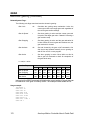
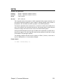
CHANGE NOTICE
Users Guide AMCS P/N PM08120 Version Change:
From: Version 1.18.04, Dated 6/30/2000
To:
Version 1.18.06 Update 15, Dated 9/28/2001
The following changes have been incorporated into Users Guide Version 1.18.06 Update 09.
1. Page 22, Memory Organization
4. Page 82, Command Reference –
Added new commands CIRCCW, CIRCW, DIP, DIN,
DZL, DZU, FFVC, FLT, KVF, KVI, KVP, LOOK,
MBUF,PASSWORD, TANG, TARC FSTAT.
Added new commands: CIRCCW, CIRCW, DIP, DIN,
DZL, DZU, FFVC, FLT, KVF, KVI, KVP, LOOK,
MBUF,PASSWORD, TANG, TARC.
Added new commands: CIRCCW, CIRCW, DIP, DIN,
DZL, DZU, FFVC, FLT, KVF, KVI, KVP, LOOK,
MBUF,PASSWORD, TANG, TARC FSTAT.
Added CIRCCW command.
5. Page 83, Command Reference –
Added CIRCW command.
6. Page 129, Command Reference –
Added CMT LOCK AMP command.
7. Page 129, Command Reference –
Added DIN command.
8. Page 130, Command Reference –
Added DIP command.
9. Page 133, Command Reference –
Added DZL command.
10. Page 134, Command Reference –
Added DZU command.
11. Page147, Command Reference –
Added FFVC command.
12. Page155, Command Reference –
Added FLT command.
13. Page 161, Command Reference –
Added FSTAT command.
14. Page 223, Command Reference –
Added KVF command.
15. Page 224, Command Reference –
Added KVI command.
16. Page 225, Command Reference –
Added KVP command.
17. Page 233, Command Reference –
Added LOOK command.
18. Page243, Command Reference –
Added MBUF command.
19. Page 261, Command Reference –
Added PASSWORD command.
20. Page 320, Command Reference –
Added TANG command.
21. Page 322, Command Reference –
Added TARC command
2. Page 33, Command Groups
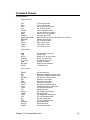
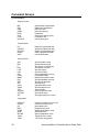
3. Page 38, Command Cross
Reference
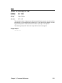
CHANGE NOTICE, continued
Users Guide AMCS P/N PM08120 Version Change:
From: Version 1.18.02, Dated 10/21/1999
To:
Version 1.18.04, Dated 6/30/2000
The following changes have been incorporated into Users Guide Version 1.18.04:
22. Acroloop Motion Controller User’s
Guide
Split manual into two (2) sections, Part I and Part II.
23. Page 1, Introduction
Added manual section content information.
24. Page 22, Memory Organization
Added new commands: MAXVEL, NURB, SPLINE,
TOV
25. Page 33, Command Groups
Added new commands: MAXVEL, NURB, SPLINE,
TOV
26. Page 38, Command Cross
Reference
Added new commands: CAM ON TRG,
CONFIG CLEAR, GEAR ON TRG, GEAR OFF TRG,
MAXVEL, NURB, SPLINE, TOV
27. Page 50, Command Reference –
ADC NEG
Corrected differential analog input example.
28. Page 68, Command Reference –
CAM
Added CAM ON TRG to cam command combinations.
29. Page 80, Command Reference –
CAM ON TRG
Added CAM ON TRG command.
30. Page 102, Command Reference –
CONFIG
Added CLEAR command to vaid CONFIG command
combinations.
Corrected CONFIG usage examples.
31. Page 105, Command Reference –
CONFIG CLEAR
Added CONFIG CLEAR command. Command was
taken out of manual after version 1.13.03, but was still
a valid firmware command.
32. Page 106, Command Reference –
CONFIG IO and CONFIG XIO
Added note about using the two commands together.
Update Usage Example to show both commands.
33. Page 115, Command Reference –
DGAIN
Added DGAIN Smooth parameter reference.
34. Page 136, Command Reference –
ELOAD
Added flash reference information.
35. Page 138, Command Reference –
ENC RD ABS
Added read Yaskawa absolute encoder command.
CHANGE NOTICE, continued
Users Guide Version 1.18.04 changes, continued:
36. Page 141, Command Reference –
ERASE
Added flash reference information.
37. Page 142, Command Reference –
ESAVE
Added flash reference information.
38. Page 146, Command Reference –
FFACC
Corrected acceleration and FFACC references.
39. Page 154, Command Reference –
FLASH
Added warning about using FLASH SAVE and FLASH
IMAGE when data is already present in flash.
40. Page 167, Command Reference –
GEAR
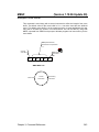
Added GEAR ON TRG and GEAR OFF TRG to valid
GEAR command combinations. Included new
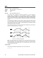
commands in Figure 3.8, Electronic Gearing Diagram.
41. Page 178, Command Reference –
GEAR ON TRG
Added GEAR ON TRG command.
42. Page 179, Command Reference –
GEAR OFF TRG
Added GEAR OFF TRG command.
43. Page 198, Command Reference –
INTCAP
Correced Valid Interrupt Source Modes for ACR1200.
Clarified usage examples.
44. Page 242, Command Reference –
MAXVEL
Added MAXVEL command.
45. Page 247, Command Reference –
MOV
Corrected incremental move command using a
forward slash.
46. Page 248, Command Reference –
MSEEK
Included unit information to MSEEK.
47. Page 253, Command Reference –
NURB
Added NURB commands, including NURB MODE,
NURB RANK, and NURB END.
48. Page 264, Command Reference –
PERIOD
49. Page 307, Command Reference –
SPLINE
Changed lower period range to 200microseconds.
50. Page 330, Command Reference –
TOV
Added TOV command.
51. Page 341, Command Reference –
VER
Added diagnostic parameter reference.
Added SPLINE commands, including SPLINE MODE
and SPLINE END.
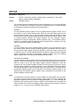
CHANGE NOTICE, continued
Users Guide AMCS P/N PM08120 Version Change:
From: Version 1.17.07, Dated 5/21/1998
To:
Version 1.18.02, Dated 10/21/1999
The following changes have been incorporated into Users Guide Version 1.18.02:
1. Cover Page
Changed User’s Guide title to reflect general controller
name.
2. Page 1, INTRODUCTION
Added ACR1200, ACR1500, and ACR8010 board
information.
3. Page 5,Chapter 1 Overview
Added ACR1200, ACR1500, and ACR8010 hardware
manual information.
4. Page 9, Chapter 2 Overview
Added ACR1200, ACR1500, ACR8010 board
references.
5. Page 10 ~ 13, Communication
Channels
Added ACR1200, ACR1500, ACR8010 board
references.
6. Page 14, System Attachments
Added ACR1200, ACR1500, ACR8010 board
references.
7. Page 18 ~ 25, Memory
Organization
Added ACR1200, ACR1500, ACR8010 Memory
Organization descriptions.
8. Page 33, Command Groups
Added CMT object to Global objects group.
Added TMOV and SYNC to velocity profile group.
9. Page 38, Command Cross
Reference
Added Command Cross Reference chart to manual.
10. Page 44, Command Reference,
ADC Command
Added ADC command information
11. Page 46, Command Reference,
ADC Command
Added ADC mode command
12. Page 55, Command Reference,
ADC Command
Added ADC max command
13. Page 48, Command Reference,
ADC Command
Added ADC scale command
14. Page 59, Command Reference,
ATTACH AXIS Command
Added CMT object as an additional option for output
signal
CHANGE NOTICE, continued
Users Guide Version 1.18.02 changes, continued:
15. Page 65, Command Reference,
BRESET Command
Added ACR1200/ACR1500/ACR8010 references.
16. Page 87 ~ 101, Command
Reference, CMT Command
Added CMT command
17. Page 102, Command Reference,
CONFIG Command
Added ACR1200/ACR1500/ACR8010 references and
additional examples.
18. Page 107, Command Reference,
CONFIG IO MODE Command
Added ACR1500 command.
19. Page 108, Command Reference,
CONFIG IO INPUT Command
Added ACR1500 command.
20. Page 108, Command Reference,
CONFIG IO OUT Command
Added ACR1500 command.
21. Page 116 ~ 124, Command
Reference, DIAG Command
Added ACR1200/ACR1500/ACR8010 references.
22. Page 125, Command Reference,
DIM Command
Added DIM LOGGING(size) command
23. Page 154, Command Reference,
FLASH Command
Added ACR1200/ACR1500/ACR8010 references.
24. Page 186 ~ 188, Command
Reference, HSINT Command
Added ACR1200/ACR1500/ACR8010 references and
new HSINT format
25. Page 198 ~ 208, Command
Reference, INTCAP Command
Added ACR1200/ACR1500/ACR8010 references and
new INTCAP format
26. Page 248 , Command Reference,
MSEEK Command
Added ACR1200/ACR1500/ACR8010 references and
new MSEEK format
27. Page 264 , Command Reference,
PERIOD Command
Added ACR1200/ACR1500/ACR8010 references and
new default value for ACR1500
28. Page 279 , Command Reference,
PROM Command
Added ACR1200/ACR1500/ACR8010 references.
29. Page 314 ~318, Command
Reference, SYNC Command
Added new SYNC commands
CHANGE NOTICE, continued
Users Guide Version 1.18.02 changes, continued:
30. Page 326 ~ 329, Command
Reference, TMOV Command
Added new TMOV Commands
31. Page 395, PLC Programming, PLC
Operation
For ACR8010, the maximum plc instruction for each
plc program is increased from 100 to 200
CHANGE NOTICE, continued
Users Guide AMCS P/N PM08120 Version Change:
From: Version 1.17.05, Dated 12/5/97
To:
Version 1.17.07, Dated 5/21/98
The following changes have been incorporated into Users Guide Version 1.17.07 and above:
52. Page 13, System Reference,
Multiple Board Communication
Corrected usage example.
53. Page 18, System Reference,
Memory Organization
Corrected expanded memory figure.
54. Page 25, System Reference,
Memory Organization
Added FLASH IMAGE command reference.
55. Page 65, Command Reference,
BRESET Command
Added ACR2000/ACR8000/ACR8010 command
information.
56. Page 84, Command Reference,
CLEAR Command
Corrected spelling.
57. Page 107, Command Reference,
CPU Command
Added period command reference.
58. Page 125, Command Reference,
DIM Command
Added minimum stream buffer size information.
59. Page 154, Command Reference,
FLASH Command
Added Flash Image command and Flash Bypass
Mode information.
60. Page 160, Command Reference,
FOV Command
Clarified feedrate override description to include move
type – feed move.
61. Page 186, Command Reference,
HSINT Command
Clarified mode definition location information.
62. Page 248, Command Reference,
MSEEK Command
Clarified mode definition location information. Added
recommended clearing of register information.
63. Page 264, Command Reference,
PERIOD Command
Added recommended foreground/background timing
information.
64. Page 291, Command Reference,
ROV Command
Clarified rapid feedrate override description to include
move type – rapid move.
65. Page 345, Expression Groups
Corrected spelling error.
CONTENTS
BSC ........................................................... 66
CAM........................................................... 68
CLEAR................................................... 71
DIM ........................................................ 72
SEG ....................................................... 73
SRC ....................................................... 74
INTRODUCTION......................................... 1
CHAPTER 1
HARDWARE INSTALLATION ................... 3
Chapter Overview ....................................... 5
RES...........................................................75
CHAPTER 2
SYSTEM REFERENCE .............................. 7
ON.......................................................... 76
OFF........................................................ 76
SCALE ................................................... 77
OFFSET................................................. 77
FLZ......................................................... 78
SHIFT .................................................... 78
RES........................................................ 79
TRG ....................................................... 80
TRGP..................................................... 81
CIRCCW.................................................... 82
CIRCW ...................................................... 83
CLEAR ...................................................... 84
CLOSE ...................................................... 85
CLR ........................................................... 86
CMT........................................................... 87
ANG ....................................................... 94
DAC ....................................................... 94
ENC ....................................................... 95
ERPMR.................................................. 95
HSEEK................................................... 96
LOCK AMP ............................................ 96
LOCK COUNT ....................................... 97
LOCK RANGE ....................................... 97
MAX AMP .............................................. 98
MAX RPM .............................................. 99
MODE .................................................... 99
OFF...................................................... 100
ON........................................................ 100
PPR...................................................... 101
SHIFT .................................................. 101
CONFIG .................................................. 102
CLEAR................................................. 105
IO ......................................................... 106
XIO....................................................... 106
IO ......................................................... 107
XIO....................................................... 108
XIO....................................................... 108
CPU ......................................................... 109
DAC ......................................................... 110
DEC ......................................................... 111
DEF ......................................................... 112
DEFINE ................................................... 113
DETACH.................................................. 114
DGAIN ..................................................... 115
Chapter Overview ....................................... 9
Communication Channels......................... 10
Communication Levels.............................. 12
Multiple Board Communication ................. 13
System Attachments ................................. 14
Command Input Modes............................. 15
Memory Organization................................ 16
Variable Memory Allocation ...................... 26
Parametric Evaluation ............................... 27
Servo Loop................................................ 28
Digital Filters ............................................. 29
Position Velocity Servo Loop .................... 30
CHAPTER 3
COMMAND REFERENCE........................ 31
Command Groups..................................... 33
Command Cross Reference ..................... 38
ACC........................................................... 43
ADC........................................................... 44
MODE.................................................... 46
MAX ....................................................... 47
SCALE................................................... 48
POS ....................................................... 49
NEG ....................................................... 50
GAIN ...................................................... 51
OFFSET ................................................ 51
ON ......................................................... 52
OFF ....................................................... 52
ADCX ........................................................ 53
MODE.................................................... 54
MAX ....................................................... 55
ALM ........................................................... 56
ATTACH.................................................... 57
MASTER................................................ 58
SLAVE ................................................... 58
AXIS....................................................... 59
AUT ........................................................... 60
AXIS .......................................................... 61
BKL............................................................ 62
BLK............................................................ 63
BLM ........................................................... 64
BRESET .................................................... 65
i
DIAG........................................................ 116
DIM.......................................................... 125
DIN .......................................................... 129
DIP .......................................................... 130
DWIDTH .................................................. 131
DWL ........................................................ 132
DZL.......................................................... 133
DZU ......................................................... 134
ECHO ...................................................... 135
ELOAD .................................................... 136
ENC......................................................... 137
ENC RD ABS .......................................... 138
END......................................................... 140
ERASE .................................................... 141
ESAVE .................................................... 142
EXC ......................................................... 143
F .............................................................. 144
FBVEL ..................................................... 145
FFACC .................................................... 146
FFVC ....................................................... 147
FIRMWARE............................................. 148
UPGRADE........................................... 151
BACKUP.............................................. 152
CHECKSUM ........................................ 152
FFVEL ..................................................... 153
FLASH..................................................... 154
FLT .......................................................... 155
SRC ..................................................... 156
OUT ..................................................... 156
ON ....................................................... 157
OFF...................................................... 157
FLZ .......................................................... 158
FOR / TO / STEP / NEXT........................ 159
FOV ......................................................... 160
FSTAT ..................................................... 161
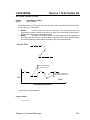
FVEL ....................................................... 166
GEAR ...................................................... 167
CLEAR................................................. 171
SRC ..................................................... 172
PPU ..................................................... 172
RATIO.................................................. 173
RES ..................................................... 173
ACC ..................................................... 174
DEC ..................................................... 175
ON ....................................................... 176
OFF...................................................... 176
MIN ...................................................... 177
MAX ..................................................... 177
ON TRG............................................... 178
ON TRGP ............................................ 179
OFF TRG............................................. 179
OFF TRGP .......................................... 180
GOSUB ................................................... 181
GOTO...................................................... 182
HALT ....................................................... 183
HDW........................................................ 184
HELP ....................................................... 185
HSINT...................................................... 186
IDELAY.................................................... 189
IF / THEN................................................. 190
IF / ELSE IF / ELSE /ENDIF.................... 191
IGAIN....................................................... 192
IHPOS ..................................................... 193
ILIMIT ...................................................... 194
INH .......................................................... 195
INPUT...................................................... 196
INT........................................................... 197
INTCAP ................................................... 198
OFF...................................................... 209
IPB........................................................... 210
ITB ........................................................... 211
IVEL......................................................... 212
JLM.......................................................... 213
JOG ......................................................... 214
VEL ...................................................... 216
JRK ...................................................... 216
ACC ..................................................... 217
DEC ..................................................... 217
RES...................................................... 218
REN ..................................................... 218
FWD..................................................... 219
REV...................................................... 219
OFF...................................................... 220
SRC ..................................................... 220
INC....................................................... 221
ABS...................................................... 221
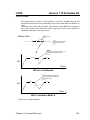
JRK.......................................................... 222
KVF.......................................................... 223
KVI........................................................... 224
KVP ......................................................... 225
RATCH .................................................... 226
SRC ..................................................... 227
FREQ ................................................... 227
WIDTH ................................................. 228
MULT ................................................... 228
LIST ......................................................... 229
LISTEN .................................................... 230
LOCK....................................................... 231
LOOK....................................................... 233
ON........................................................ 234
OFF...................................................... 234
MODE .................................................. 235
ANG ..................................................... 236
LOPASS .................................................. 238
LRUN....................................................... 239
MASK ...................................................... 240
MASTER.................................................. 241
MAXVEL .................................................. 242
MBUF ...................................................... 243
ON........................................................ 244
OFF...................................................... 244
MEM ........................................................ 245
ii
MODE ..................................................... 246
MOV ........................................................ 247
MSEEK.................................................... 248
MULT ...................................................... 249
NEW ........................................................ 250
NORM ..................................................... 251
NOTCH ................................................... 252
NURB ...................................................... 253
MODE.................................................. 257
RANK................................................... 258
END ..................................................... 258
OFFSET .................................................. 259
OPEN ...................................................... 260
PASSWORD ........................................... 261
ON ....................................................... 261
OFF ..................................................... 261
PAUSE .................................................... 262
PBOOT.................................................... 263
PERIOD .................................................. 264
PGAIN ..................................................... 265
PLC ......................................................... 266
PLS.......................................................... 267
SRC ..................................................... 270
DST ..................................................... 270
BASE ................................................... 271
RES ..................................................... 271
ROTARY.............................................. 272
FLZ ...................................................... 272
MASK .................................................. 273
RATIO.................................................. 273
ON ....................................................... 274
OFF ..................................................... 274
PPU ......................................................... 275
PRINT ..................................................... 276
PROG...................................................... 277
PROGRAM / ENDP................................. 278
PROM ..................................................... 279
RATCH.................................................... 280
SRC ..................................................... 281
MODE.................................................. 282
REBOOT ................................................. 283
REM ........................................................ 284
REN......................................................... 285
RES ......................................................... 286
RESUME................................................. 287
RETURN ................................................. 288
ROTARY ................................................. 289
ROTATE.................................................. 290
ROV......................................................... 291
RUN ........................................................ 292
SAMP ...................................................... 293
SRC ..................................................... 298
BASE ................................................... 298
CLEAR................................................. 299
TRG ..................................................... 299
SCALE .................................................... 300
SET.......................................................... 301
SINE ........................................................ 302
SPLINE.................................................... 307
MODE .................................................. 309
END ..................................................... 310
SRC ......................................................... 311
STEP ....................................................... 312
STP.......................................................... 313
SYNC....................................................... 314
ON........................................................ 317
MDI ...................................................... 317
PROG .................................................. 318
OFF...................................................... 318
SYS ......................................................... 319
TANG....................................................... 320
ON........................................................ 320
OFF...................................................... 321
TARC....................................................... 322
ON........................................................ 323
OFF...................................................... 324
TLM ......................................................... 325
TMOV ...................................................... 326
ON........................................................ 328
OFF...................................................... 328
VEL ...................................................... 329
TOV ......................................................... 330
TRG ......................................................... 331
TRJ .......................................................... 332
TROFF .................................................... 333
TRON ...................................................... 334
UNLOCK ................................................. 335
VECDEF .................................................. 336
VECTOR ................................................. 338
VEL.......................................................... 339
LIMIT.................................................... 340
VER ......................................................... 341
WHILE / WEND ....................................... 342
CHAPTER 4
EXPRESSION REFERENCE.................. 343
Expression Groups.................................. 345
+ .............................................................. 347
- ............................................................... 347
* ............................................................... 347
/................................................................ 347
**.............................................................. 347
<< ............................................................ 348
>> ............................................................ 348
< .............................................................. 349
= .............................................................. 349
> .............................................................. 350
<> ............................................................ 350
<= ............................................................ 351
>= ............................................................ 351
ACOS ...................................................... 352
ACOSH.................................................... 352
iii
ACOT ...................................................... 353
ACOTH.................................................... 353
AND......................................................... 354
ASC ......................................................... 355
ASIN ........................................................ 356
ASINH ..................................................... 356
ATAN....................................................... 357
ATANH .................................................... 357
BIT........................................................... 358
CEIL ........................................................ 359
CHR$....................................................... 360
COS......................................................... 361
COSH ...................................................... 361
COT......................................................... 362
COTH ...................................................... 362
FLOOR .................................................... 363
INKEY$.................................................... 364
INKEY$.................................................... 365
INSTR...................................................... 366
KBHIT...................................................... 367
LCASE$................................................... 368
LEFT$...................................................... 369
LEN ......................................................... 370
LN............................................................ 371
LOG......................................................... 371
MID$........................................................ 372
MOD ........................................................ 373
NAND ...................................................... 374
NOR ........................................................ 375
NOT......................................................... 376
OR ........................................................... 377
RIGHT$ ................................................... 378
RND......................................................... 379
ROUND ................................................... 380
SIN .......................................................... 381
SINH........................................................ 381
SPACE$ .................................................. 382
SQRT ...................................................... 383
STR$ ....................................................... 384
STRING$................................................. 385
TAN ......................................................... 386
TANH....................................................... 386
TRUNC.................................................... 387
UCASE$ .................................................. 388
VAL.......................................................... 389
XNOR ...................................................... 390
XOR......................................................... 391
HALT.................................................... 402
LIST ..................................................... 403
MEM..................................................... 404
PLC Instructions ...................................... 405
LD ........................................................ 406
LD NOT................................................ 407
AND ..................................................... 408
AND NOT............................................. 409
OR........................................................ 410
OR NOT ............................................... 411
AND LD................................................ 412
OR LD .................................................. 414
OUT ..................................................... 416
TIM....................................................... 417
CNT...................................................... 420
KR ........................................................ 423
PBOOT ................................................ 426
END ..................................................... 427
INDEX...................................................... 429
CHAPTER 5
PLC PROGRAMMING............................ 393
PLC Operation ........................................ 395
PLC Commands...................................... 397
PLC...................................................... 398
PON ..................................................... 399
POFF ................................................... 400
RUN ..................................................... 401
iv
TABLES
2.1 Digital filter parameters ......................... 29
2.2 Digital filter flags.................................... 29
3.1 ADC parameter cross-reference........... 44
3.2 ADC Mode............................................. 46
3.3 ADC Scale............................................. 48
3.4 ADC positive channels.......................... 49
3.5 ADC negative channels ........................ 50
3.6 'A limit' flags .......................................... 56
3.7 'Not B limit' flags.................................... 64
3.8 Echo control codes ............................. 135
3.9 'Not excess error' flags........................ 143
3.10a ACR8000 Hardware Capture Interrupt
Sources............................................... 201
3.10b ACR8000 Hardware Capture
Flags/Parameters ............................... 201
3.10c ACR2000 Hardware Capture Interrupt
Sources............................................... 202
3.10d ACR2000 Default Hardware Capture
Flags/Parameters ............................... 202
3.10c ACR8010 Hardware Capture Interrupt
Sources............................................... 203
3.10f ACR8010 Default Hardware Capture
Flags/Parameters ............................... 203
3.10g ACR1200 Hardware Capture Interrupt
Sources............................................... 204
3.10h ACR1200 Default Hardware Capture
Flags/Parameters ............................... 204
3.10i ACR1500 Hardware Capture Interrupt
Sources............................................... 205
3.10j ACR1500 Default Hardware Capture
Flags/Parameters ............................... 205
3.11 'Not in-position' flags ......................... 210
3.12 'Not in-torque band' flags .................. 211
3.13 Data formatting modes...................... 246
3.14 Ratchet Modes .................................. 282
3.15 'Not torque limit' flags........................ 325
5.1 PLC tick parameters ........................... 395
5.2 PLC operation flags ............................ 396
5.3 PLC timer cross-reference .................. 417
5.4 PLC counter cross-reference.............. 420
5.5 PLC latch cross-reference .................. 423
v
FIGURES
2.1
2.2
2.3
2.4
2.5
FIFO System Task ................................ 10
COM1/COM2 System Tasks................. 11
SYS / PROG levels ............................... 12
ACR8000 Memory Organization ........... 16
ACR1200, ACR1500, and ACR2000
Standard Memory Organization............ 17
2.6 ACR8010 Memory Organization and
ACR2000 Expanded Memory
Organization.......................................... 18
2.7 Servo loop ............................................. 28
2.8 Setpoint summation .............................. 28
2.9 Servo loop core ..................................... 28
2.10 Filter equations.................................... 29
2.11 Dead Band and Position Velocity Loop30
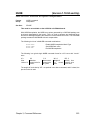
3.1 ACC/DEC/STP slopes .......................... 43
3.2 ADC input channel diagram .................. 45
3.3 Sample attachments ............................. 57
3.4 Backlash compensation ........................ 62
3.5 Sample ballscrew table ......................... 67
3.6 Sample cam table ................................. 69
3.7 Final velocity example.........................166
3.8 Electronic gearing diagram .................168
3.8a HSINT Operation Sequence .............187
3.9 Scurve velocity profile .........................222
3.9a Look Ahead Mode 0..........................233
3.9b Look Ahead Mode 1..........................235
3.9c NURB interpolation example.............255
3.10 PLS block diagram ............................268
3.11 Sinusoidal mode example.................304
3.12 Circular interpolation example ..........305
3.13 Spiral interpolation example..............306
3.14 Spline interpolation example.............308
3.15 Tangential interpolation example ......320
3.16 3-D Arc interpolation example...........323
5.1 AND LD example ................................412
5.2 OR LD example...................................414
5.3 PLC timer example..............................418
5.4 PLC counter example .........................421
5.5 PLC latch example ..............................424
vi
INTRODUCTION
This manual will serve as a reference and programmers guide for the ACR1200,
ACR1500, ACR2000, ACR8000,ACR8010 and ACR8020 family of motion controllers.
Please reference the Acroloop Motion Controller User’s Guide Part II for additional
information.
Acroloop Motion Controller User’s Guide Part I (P/N PM08120-1) includes:
Chapter 1.
Chapter 2.
Chapter 3.
Chapter 4.
Chapter 5.
Hardware Installation
System Reference
Command Reference
Expression Reference
PLC Programming
Acroloop Motion Controller User’s Guide Part II (P/N PM08120-2) includes:
Chapter 6. Binary Host Interface
Appendix A. Parameter Reference
Appendix B. Flag Reference
Appendix C. Output Modules Software Configuration Examples
The ACR8020 is a floating point DSP based 16 axis motion controller. This board will
work in standalone mode as well as within a PCI bus chassis.
The ACR8010 is a floating point DSP-based 8 axis motion controller. It has onboard
hardware to read up to eight with the option of ten incremental encoders. The board can
supply precision 16-bit analog for eight servo amplifiers or step/direction open-collector
ouputs for eight stepper drives. It is modular in nature and is offered in 2, 4, 6 or 8 axis
configurations. This board will work in standalone mode as well as within a PC-AT bus
chassis. In the PC-AT bus, the board takes one ISA card slot.
The ACR8000 is a floating point DSP-based 8 axis motion controller. It has onboard
hardware to read up to eight incremental encoders. The board can supply precision 16bit analog for eight servo amplifiers or step/direction open-collector ouputs for eight
stepper drives. It is modular in nature and is offered in 2, 4, 6 or 8 axis configurations.
This board will work in standalone mode as well as within a PC-AT bus chassis. In the
PC-AT bus, the board takes one and one half ISA slots.
The ACR2000 is a floating point DSP-based 4 axis motion controller. It has onboard
hardware to read up to four incremental encoders. The board can supply precision 16-bit
analog for four servo amplifiers or step/direction open-collector ouputs for four stepper
drives. It is modular in nature and is offered in 2 or 4 axis configurations. This board will
work in standalone mode as well as within a PC-AT bus chassis. In the PC-AT bus, the
board takes a single half-card ISA slot.
Introduction
1
Introduction, continued
The ACR1500 is a floating point DSP-based 4 axis motion controller. It has onboard
hardware to read up to four incremental encoders. The board can supply precision 16-bit
analog for four servo amplifiers or step/direction open-collector ouputs for four stepper
drives. It is modular in nature and is offered in 2 or 4 axis configurations. This board is a
PC-AT card only. In the PC-AT bus, the board takes a single half-card ISA slot.
The ACR1200 is a floating point DSP-based 2 axis motion controller. It has onboard
hardware to read up to three incremental encoders. The board can supply precision 16bit analog for two servo amplifiers or step/direction open-collector ouputs for two stepper
drives. It is modular in nature and is offered in 1 or 2 axis configurations. This board is a
standalone card only.
Version 1.18 and above:
Software commutation for brushless motors is available on ACR1200, ACR1500,
ACR8010 and ACR2000 Version 1.18 and above, only. Commutation is not available on
the ACR8000 Board.
Each commutator uses two 16-bit analog outputs to generate sinusoidal or trapezoidal
signals to command “phased sine” input type servo amplifiers. Therefore, the ACR8010
can control a maximum of four (4) axis, if they are all being commutated. The ACR1500
and ACR2000 can do a maximum of two (2) axis. The ACR1200 can be configured for a
single (1) axis of commutation.
2
Acroloop Motion Controller User’s Guide
CHAPTER 1
Hardware Installation
Chapter 1, Hardware Installation
3
This page intentionally left blank.
4
Acroloop Motion Controller User’s Guide
Chapter Overview
Description:
Hardware installation is located in the corresponding ACR1200 / ACR1500 / ACR2000 /
ACR8000 / ACR8010 / ACR8020 Hardware Reference Manual.
ACR1200 Hardware Reference Manual: AMCS Part Number PM08123
ACR1500 Hardware Reference Manual: AMCS Part Number PM08122
ACR2000 Hardware Reference Manual: AMCS Part Number PM08117
ACR8000 Hardware Reference Manual: AMCS Part Number PM08119
ACR8010 Hardware Reference Manual: AMCS Part Number PM08121
ACR8020 Hardware Reference Manual: AMCS Part Number PM08126
Chapter 1, Hardware Installation
5
This page intentionally left blank.
6
Acroloop Motion Controller User’s Guide
CHAPTER 2
System Reference
Chapter 2, System Reference
7
This page intentionally left blank.
8
Acroloop Motion Controller User’s Guide Part I
Chapter Overview
Description:
This chapter gives an overview of the architecture of the Acroloop motion controllers’
executive. This chapter must be read thoroughly before proceeding on to subsequent
chapters.
The executive is a "pre-emptive" multi-tasking operating system. As many as 16
simultaneous tasks can be open at the same time. Each of these tasks are called
"programs" and are referenced as PROG0 ... PROG15.
There are three communication channels (or streams) available on the ACR2000 /
ACR8000 / ACR8010 that can be simultaneously open to send and receive data. They
are as follows:
1.
2.
3.
COM1:
COM2:
FIFO:
(Serial RS232, RS422)
(Serial RS232, RS422)
(PC/ISA bus, port access)
There are two communication channels (or streams) available on the ACR1200 that can
be simultaneously open to send and receive data. They are as follows:
1.
2.
COM1:
COM2:
(Serial RS232, RS422)
(Serial RS232, RS422)
There is one communication channel (or stream) available on the ACR1500 that can be
open to send and receive data. This is as follows:
1.
FIFO:
(PC/ISA bus, port access)
There are three communication channels (or streams) available on the ACR8020 that
can be simultaneously open to send and receive data. They are as follows:
1.
2.
3.
COM1:
COM2:
DPCB:
(Serial RS232, RS422)
(Serial RS232, RS422)
(PC/PCI bus, dual port circular buffer)
All of the above channels can be operated simultaneously and attached to various
programs. Programs can be running while others are being edited.
All of the channels "wake-up" on power-up when seeing data. Additionally, the serial
channels have automatic baud detection that is triggered by receiving one or two
carriage returns (ASCII 13) after power-up.
Chapter 2, System Reference
9
Communication Channels
The user has the option of communicating with the ACR2000/ACR8000/ACR8010
through either the PC Bus or RS-232/RS-422 serial ports. The ACR1200 user can
communicate through RS-232/RS-422 serial ports only. The ACR1500 user can
communicate through the PC Bus only.
The ACR2000 requires the optional ACRCOMM module for serial communication.
There are three communication channels (or streams) available that can be
simultaneously open to send and receive data. They are as follows:
1.
2.
3.
COM1:
COM2:
FIFO:
(Serial RS232, RS422) (Not available on the ACR1500)
(Serial RS232, RS422) (Not available on the ACR1500)
(PC/ISA bus, port access) (Not available on the ACR1200)
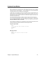
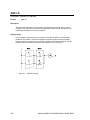
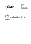
Communication Buffers:
As the commands are received by the boards, they are stored in an ASCII stream buffer.
There is a stream buffer for each of the FIFO, COM1, and COM2 system tasks. The
default buffer size is 256 bytes long.
FIFO
RCV
ASCII
STREAM
BUFFER
STATUS
SYS
XMIT
FIFO
Hardware
Interface
FIFO
System
Task
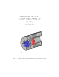
Figure 2.1
10
Binary Status
Fetch
FIFO System Task
Acroloop Motion Controller User’s Guide Part I
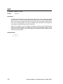
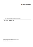
Communication Channels
COM1
ASCII
STREAM
BUFFER
SYS
COM2
DUART
COM2
COM1
Status
Requests
ASCII
STREAM
BUFFER
SYS
Status
Requests
COM1/COM2
Hardware
Interface
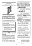
Figure 2.2
COM1/COM2
System
Tasks
COM1/COM2 System Tasks
If the system task cannot process commands faster than the data coming in from the
hardware interface by the front-end application, the ASCII buffer may become full. Once
this happens, the corresponding task (COM1, COM2, FIFO) is suspended. This in turn
will cause the hardware FIFOs to become full, causing the front-end application to
timeout based on status flags (refer to appropriate hardware manual, Address Selection
Switch (SW1) (ACR1500/ACR2000/ACR8000) or Plug and Play (ACR8010)).
ASCII buffer size (in bytes) can be changed by using the DIM command (see DIM
command). ASCII buffer size is limited by the amount of User RAM memory available for
dimensioning (see Memory Organization).
Chapter 2, System Reference
11
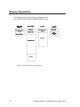
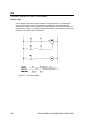
Communication Levels
Communication channels are either at the "system" level or at a "program" level. The
command prompt indicates the level that a communication channel is currently at.
System Level:
The "system" level is the level that a communication channel is at after power-up.
The command prompt at this level is as follows:
SYS>
Only a limited set of commands can be issued from this level. From any other level,
the SYS command will return the communication channel to the system level.
Program Level:
This "program" level allows the editing and running of individual programs. The
command prompt at the program level is as follows::
Pnn>
Where "nn" is the currently active program number. To select this level from any
other level, issue the PROG command followed by the program number. For
example, the following command will select program 1 no matter which level or
program is currently active:
PROG 1
To go back to the system level from the program level, execute the SYS command.
To go from one program to another program, simply issue another PROG command
followed by the desired program number.
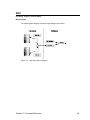
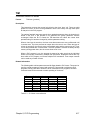
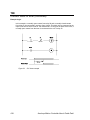
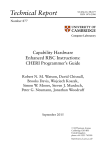
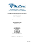
The following figure shows the various communication channel levels. The
communication channels on the left can all be active at the same time and be operating
at different levels. For example, "COM1:" could be editing program 3 while "COM2:"
monitors user variables being modified by program number 5.
Figure 2.3
12
SYS / PROG levels
Acroloop Motion Controller User’s Guide Part I
Multiple Board Communication
PC BUS:
Multiple board communication over the PC Bus is handled by using different I/O port
addresses and card numbers for each card in the system. Refer to the appropriate
ACR1500/ACR2000/ACR8000 hardware manual for Address Selection Switch (SW1)
information. Refer to ACR8010 hardware manual for ACR8010 card Plug and Play
information.
Up to eight ACR1500/ACR2000/ACR8000/ACR8010 boards can be used in the same
system.
SERIAL BUS:
Multiple board communication over the serial ports is handled by using different card
numbers for each card in the system, and using the ctrl-A and ctrl-B commands to
address the cards. Refer to the appropriate ACR1200/ACR2000/ACR8000/ACR8010
hardware manual for Address Selection Switch (SW1) and Multiple Card Wiring
information.
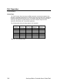
Up to eight ACR1200/ACR2000/ACR8000/ACR8010 board serial ports can be daisychained, creating a serial bus.
Symbol
Argument
Function
ctrl-A
# or <CR>
Turn on card # or all cards
ctrl-B
# or <CR>
Turn off card # or all cards
The ctrl-A and ctrl-B commands may be terminated by an ASCII character representing
the card number, i.e. “0” represents the first card and the zero key on a keyboard, or by a
carriage return (<CR>). A <CR> in this case means “all cards”. Other commands are
terminated by a <CR>.
NOTE: Only one board should be enabled (turned on) at a time, to allow for proper
handling of unsolicited responses (i.e., error messages, printing tasks, responses from
LRUN command, etc.) from individual cards.
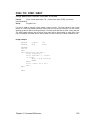
Usage Example:
The following example shows two cards (Card Number 0 and Card Number 1) being
controlled via the serial port:
ctrl-B<CR>
ctrl-A 0<CR>
PROG0<CR>
ACC 10<CR>
DEC 10<CR>
VEL 2000<CR>
ctrl-B 0<CR>
ctrl-A 1<CR>
PROG2<CR>
ACC 10<CR>
DEC 10<CR>
VEL 1000
Chapter 2, System Reference
Turn all cards off.
Turn on Card Number 0.
Program 0 for Card Number 0.
Set ACC to 10 for Card Number 0.
Set DEC to 10 for Card Number 0.
Set VEL to 2000 for Card Number 0.
Turn off Card Number 0.
Turn on Card Number 1.
Program 2 for Card Number 1.
Set ACC to 10 for Card Number 1.
Set DEC to 10 for Card Number 1.
Set VEL to 1000 for Card Number 1.
13
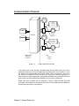
System Attachments
The following is an overview of the "objects" involved in system attachment:
-
-
-
-
-
-
On the ACR8010, there are ten input channels for reading incremental encoders.
These are referenced as ENC0 through ENC9.
On the ACR8000, there are eight input channels for reading incremental encoders.
These are referenced as ENC0 through ENC7.
On the ACR2000 and ACR1500, there are four input channels for reading
incremental encoders. These are referenced as ENC0 through ENC3.
On the ACR1200, there are three input channels for reading incremental encoders.
These are referenced as ENC0 through ENC7.
On the ACR8010/ACR8000, there are eight output channels for controlling the D/A
converters. These are referenced as DAC0 through DAC7.
On the ACR2000 and ACR1500, there are four output channels for controlling the
D/A converters. These are referenced as DAC0 through DAC3.
On the ACR1200, there are two output channels for controlling the D/A converters.
These are referenced as DAC0 through DAC1.
On the ACR8010/ACR8000, there are eight position interpolation and servo loop
control units. These are referenced as AXIS0 through AXIS7.
On the ACR2000 and ACR1500, there are four position interpolation and servo loop
control units. These are referenced as AXIS0 through AXIS3.
On the ACR1200, there are two position interpolation and servo loop control units.
These are referenced as AXIS0 through AXIS1.
On the ACR8010/ACR8000, there are eight master velocity profiles for controlling the
axes. These are referenced as MASTER0 through MASTER7.
On the ACR2000 and ACR1500, there are four master velocity profiles for controlling
the axes. These are referenced as MASTER0 through MASTER3.
On the ACR1200, there are two master velocity profiles for controlling the axes.
These are referenced as MASTER0 through MASTER1.
On the ACR8010/ACR8000, each master profiler has eight internal attachment points
for axes. These are referenced as SLAVE0 through SLAVE7.
On the ACR2000 and ACR1500, each master profiler has four internal attachment
points for axes. These are referenced as SLAVE0 through SLAVE3.
On the ACR1200, each master profiler has two internal attachment points for axes.
These are referenced as SLAVE0 through SLAVE1.
There are 16 programs with internal attachment points for masters. These are
referenced as PROG0 through PROG15.
In order for an axis to do a motion profile in either MDI or program mode, it must be
attached as the slave of a master and the master must be attached to a program. Axes
are accessed with axis names of up to 4 characters in length. This name is assigned to
the axis when it is attached to its master. See the ATTACH command for examples.
The question of how many masters to use and what axes to attach to it is largely a user
choice made initially on the type of machine. If there are 6 axis in total and they are
broken into two XYZ pick and place robots, then use two masters and two programs,
attaching three axis to each of the masters. Since the axes are attached to different
masters, they can be named X,Y and Z in both programs.
Once the relationship between a program, master, and axes has been established, it can
be canceled by using the DETACH command.
14
Acroloop Motion Controller User’s Guide Part I
Command Input Modes
Most commands can be executed either in MDI (Manual Data Input) mode or program
mode (from within a stored program.) Some commands can only be issued as MDI
commands and others can only appear in stored programs.
In MDI mode, the commands get executed immediately as they are entered while in the
program mode, the commands are stored in memory as they are entered. They can be
executed later by issuing a RUN command in the MDI mode. Program mode entry is not
allowed from the system level.
Any command that is preceded by a valid line number will get stored into the memory
of the currently selected program. Valid line numbers are in the range of 1..65000. Each
line in a program must have a line number. These line numbers are also used as
destination addresses for GOTO commands.
As an example, the following set of commands will do the identical motion profile but will
illustrate the difference between the MDI mode and the program mode.
Program usage example:
PROG0
10 ACC 10000 DEC 10000 STP10000 VEL 20000
20 X100000
30 END
RUN
MDI usage example:
PROG0
ACC10000 DEC 10000 STP 10000 VEL 20000
X100000
Chapter 2, System Reference
15
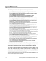
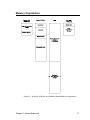
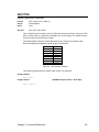
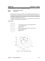
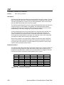
Memory Organization
The following figures show the memory organization of the
ACR1200/ACR1500/ACR2000/ACR8000/ACR8010 boards:
Figure 2.4 ACR8000 Memory Organization
16
Acroloop Motion Controller User’s Guide Part I
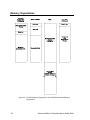
Memory Organization
Figure 2.5 ACR1200, ACR1500, and ACR2000 Standard Memory Organization
Chapter 2, System Reference
17
Memory Organization
Figure 2.6 ACR8010 Memory Organization and ACR2000 Expanded Memory
Organization
18
Acroloop Motion Controller User’s Guide Part I
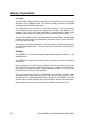
Memory Organization
There are five types of memory blocks in the ACR1200 / ACR1500 / ACR2000 /
ACR8000 / ACR8010 memory organization as described below:
EPROM:
The EPROM is a Electrically Programmable Read Only Memory. The EPROM’s main
function is to store the executable firmware code. The EPROM is programmed at the
factory and is not programmable by the user.
The EPROM-based code in the ACR8000 runs at one wait-state (148 ns using a 27MHz
System Clock), at two wait-states for the ACR1200 and ACR1500 (150ns using a 40MHz
System Clock), and at two wait-states for the Standard Memory ACR2000 (120 ns using
a 50MHz System Clock). The code for the ACR8010 and the Expanded Memory
ACR2000 does not run out of the EPROM, but out of the system RAM (see below).
The ACR8000, ACR1200, ACR1500, and Standard Memory ACR2000 EPROMs also
contain a section of shadow code, which is loaded into the System RAM memory at
power-up or reset. The ACR8010 and the Expanded Memory ACR2000 EPROM load all
of the executable firmware code into the Expanded System RAM memory at power-up or
reset. The code that is loaded into RAM runs at zero wait-states.
System RAM:
The System RAM is Static Random Access Memory. This memory is not battery backedup.
The System RAM’s functions are to store system parameters and flag information and to
store the shadow code, which is copied into the System RAM from the EPROM by the
DSP.
The System RAM runs at zero wait-state for the ACR8000 (74 ns using a 27MHz System
Clock), the ACR1200 and ACR1500 (50 ns using a 40MHz System Clock), and Standard
Memory ACR2000 (40 ns using a 50MHz System Clock). This allows fast access by the
DSP for the system parameters and flags information, as well as the speed critical
shadow code for the main servo system interrupt.
The executable code for the ACR8010 and the Expanded Memory ACR2000 is copied
into the System RAM from the EPROM by the DSP. All of the executable code then runs
at zero wait-state (40 ns using a 50MHz System Clock for Expanded Memory ACR2000,
33 ns using a 60MHz System Clock for ACR8010), which increases system performance.
Chapter 2, System Reference
19
Memory Organization
User RAM:
The User RAM is battery backed-up Static Random Access Memory for the ACR1200,
ACR8000, and the ACR8010 board. This memory is battery backed-up for ACR2000
boards with the ACRCOMM Module option.
The main function of the User Ram is to store user information. The user determines
what is stored into these memories by using the DIM command. User programs, PLC
programs, FIFO, COM1, and COM2 stream buffers, CAM and ballscrew tables, global
variables, program variables, and program arrays are all stored in these memories.
There is also dedicated section of User RAM which stores Global Data. The global data
provides User RAM locations and dimensioning information, which is used by the DSP,
for all of the above user data.
This memory is not battery backed-up for ACR1500 boards or ACR2000 boards without
the ACRCOMM Module option. The user must load the data each time the board is
powered-up.
EEPROM:
The EEPROM is an Electrically Erasable Programmable Read-Only Memory on the
ACR8000 board.
The EEPROM’s functions include storing system parameters and board configuration
information.
System parameters are stored using the ESAVE command and loaded into the card
using the ELOAD command. System parameters can be updated in the EEPROM by
first erasing the existing parameters, using the ERASE command, and then using the
ESAVE command to store the new information.
The system parameters stored in the EEPROM using the ESAVE command include
system attachments, master parameters (ACC, DEC, and STP ramps, and VEL, FVEL,
and IVEL values), axis parameters (gain and limit setting, PPU and VECDEF values, and
ON/OFF states), encoder multipliers, DAC gains and offsets, and ADC gains and offsets.
Board configuration information is stored when the CONFIG commands are used.
20
Acroloop Motion Controller User’s Guide Part I
Memory Organization
Flash:
The Flash is an Electrically Erasable Programmable Read-Only Memory on the
ACR1200, ACR1500, ACR2000, and ACR8010 boards.
The Flash’s functions include storing system parameters, board configuration information
and user programs.
System parameters are stored using the ESAVE command and loaded into the card
using the ELOAD command. System parameters can be updated in the Flash by first
erasing the existing parameters, using the ERASE command, and then using the ESAVE
command to store the new information.
The system parameters stored in the Flash using the ESAVE command include system
attachments, master parameters (ACC, DEC, and STP ramps, and VEL, FVEL, and IVEL
values), axis parameters (gain and limit setting, PPU and VECDEF values, and ON/OFF
states), encoder multipliers, DAC gains and offsets, and ADC gains and offsets.
Board configuration information is stored when the CONFIG commands are used.
Program storage uses the FLASH commands (FLASH LOAD, FLASH ERASE, FLASH
SAVE, FLASH IMAGE). At power-up or reset, the DSP detects if programs are present
in the Flash, and if they are present, loads them into User RAM, overwriting any battery
back-up programs. The tables, buffers, variables and arrays stored in the User RAM are
not written over.
Chapter 2, System Reference
21
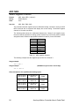
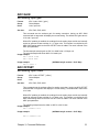
Memory Organization
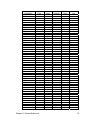
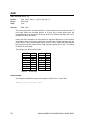
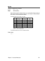
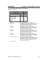
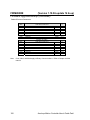
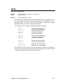
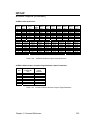
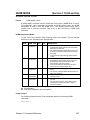
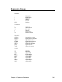
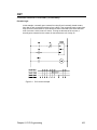
The following table shows the type(s) of memory associated with system commands:
COMMAND
ACC
ADC
ADCX
ALM
ATTACH
AUT
AXIS
BKL
BLK
BLM
BRESET
BSC
CAM
CIRCCW
CIRCW
CLEAR
CLOSE
CLR
CMT
CONFIG
CPU
DAC
DEC
DEF
DEFINE
DETACH
DGAIN
DIAG
DIM
DIN
DIP
DWIDTH
DWL
DZL
DZU
ECHO
ELOAD
ENC
ENC RD ABS
END
ERASE
ESAVE
EXC
F
FBVEL
FFACC
22
System
RAM
X
X
X
X
X
User
RAM
EPROM
EEPROM/
Flash
X
X
X
X
X
N/A
X
X
X
X
X
X
X
X
X
X
X
X
X
X
X
X
X
X
X
X
X
X
X
X
X
X
X
X
X
X
X
X
X
X
X
X
X
X
X
X
X
X
X
X
X
X
X
X
X
X
X
X
Acroloop Motion Controller User’s Guide Part I
COMMAND
FFVEL
FFVC
FLASH
FLT
FLZ
FOR
FOV
FVEL
FSTAT
GEAR
GOSUB
GOTO
HALT
HDW
HELP
HSINT
IDELAY
IF / THEN
IF / ELSE /ENDIF
IGAIN
IHPOS
ILIMIT
INH
INPUT
INT
INTCAP
INVK
IPB
ITB
IVEL
JLM
JOG
JRK
KVF
KVI
KVP
LIMIT
LIST
LISTEN
LOCK
LOOK
LOPASS
LRUN
MASK
MASTER
MAXVEL
MBUF
MEM
MODE
MOV
MSEEK
MULT
System
RAM
X
X
User
RAM
EPROM
EEPROM/
Flash
X
N/A
X
X
X
X
X
X
X
X
X
X
X
X
X
X
X
X
X
X
X
X
X
X
X
X
X
X
X
X
X
X
X
X
X
X
X
X
X
X
X
X
X
X
X
X
X
X
X
X
X
X
X
X
X
X
X
X
X
X
X
X
Chapter 2, System Reference
X
23
COMMAND
NEW
NORM
NOTCH
NURB
OFFSET
OPEN
PASSWORD
PAUSE
PBOOT
PERIOD
PGAIN
PLC
PLS
PPU
PROG
PROGRAM
PROM
RATCH
REBOOT
REM
REN
RES
RESUME
RETURN
ROTARY
ROTATE
ROV
RUN
SAMP
SCALE
SET
SINE
SPLINE
SRC
STEP
STP
SYNC
SYS
TANG
TARC
TLM
TMOV
TOV
TRG
TRJ
TROFF
TRON
UNLOCK
VECDEF
VECTOR
VEL
VER
24
System
RAM
User
RAM
X
EPROM
EEPROM/
Flash
N/A
X
X
X
X
X
X
X
X
X
X
X
X
X
X
X
X
X
X
X
X
X
X
X
X
X
X
X
X
X
X
X
X
X
X
X
X
X
X
X
X
X
X
X
X
X
X
X
X
X
X
X
X
X
X
X
X
X
X
X
X
Acroloop Motion Controller User’s Guide Part I
COMMAND
WHILE
System
RAM
Chapter 2, System Reference
User
RAM
EPROM
EEPROM/
Flash
N/A
X
25
Variable Memory Allocation
For the following definitions, xxx and yyy are positive numbers. Their range depends on
memory limitations. There are two sets of memory types that are accessible by each
program, global system and local user parameters.
The global system parameter definitions are listed in Chapter 6. Each parameter number
is preceded by the letter "P". For example, the following command will load system
parameter 4097 with the value 123:
P4097 = 123
In addition to the global system parameters that can be accessed by all programs, each
program can dimension (allocate) local parameters. These parameters can be either
single variables or arrays of variables.
The following formats are used to access the different types of variables:
Pxxx
BITxxx
Global system variable xxx.
Global bit flag xxx
LVxxx
LAxxx(yyy)
SVxxx
SAxxx(yyy)
DVxxx
DAxxx(yyy)
$Vxxx
$Axxx(yyy)
Local Long (32 bit integer) variable xxx.
Local Long array number xxx and index yyy.
Local Single ( 32 bit floating point ) variable xxx.
Local Single array number xxx and index yyy.
Local Double ( 64 bit floating point ) variable xxx.
Local Double array number xxx and index yyy.
Local String ( packed 8 bit ) variable xxx.
Local String array number xxx and index yyy.
Global user variables are referenced as P0..P4095. The actual number of global user
variables is determined by the DIM P command from the system level. Global system
parameters are referenced according to the tables in Appendix A.
Local user variables are referenced by their type, followed by a number. The following
command will load the number 1234 into the first long integer variable:
LV0 = 1234
The local arrays are referenced by an array number and index. The following command
will load the number 1234 into the fifth element of the first long integer array:
LA0(4) = 1234
Only the amount of memory remaining limits how many parameters can be allocated.
The DIM command is used to declare the parameters and the CLEAR command to
release them. Full floating point math is allowed to operate on global and local variables.
26
Acroloop Motion Controller User’s Guide Part I
Parametric Evaluation
There is a built-in floating point evaluator that operates on the global and local variables.
The following operators are available:
Arithmetic:
Trigonometric:
Hyperbolic:
Logarithmic:
Comparison:
Logical:
Miscellaneous:
String:
+ - * / **
SIN COS TAN ATAN ACOS ASIN
SINH COSH TANH ATANH ACOSH ASINH
LOG LN
= <> < > >= <=
AND OR XOR NAND NOR XNOR NOT << >>
SQRT RND
CHR$ ASC LEN STR$ VAL INSTR
LCASE$ UCASE$ SPACE$ STRING$
LEFT$ RIGHT$ MID$ INKEY$ KBHIT
The following are an example of valid statements assuming that the parameters have
been properly dimensioned and the X and Y attachments have been defined:
LV1 = LV2+LV3*(LV5+LV6)
IF ((LV5+LV6*LV9) < 10 ) THEN GOTO 100
X(LV1+LV2) Y(3*LV5)
Note that the arguments of X and Y are enclosed in parentheses. This is the way that
parametric arguments are given to a command. All commands will accept parametric
arguments.
A special character is used to signify incremental distance for axis moves. This character
is the forward slash "/". It must precede the numerical or parametric argument for
incremental axis moves. As an example, the following command will move the X axis 20
units in the positive direction from its current location:
X /20
It is possible to mix absolute, incremental, and parametric moves as follows:
X2.5 Y/1.23 Z/(DV2*DV3)
Chapter 2, System Reference
27
Servo Loop
28
Figure 2.7
Servo loop
Figure 2.8
Setpoint summation
Figure 2.9
Servo loop core
Acroloop Motion Controller User’s Guide Part I
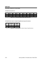
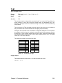
Digital Filters
Filter Equations:
Figure 2.10
Filter equations
Filter Parameters:
Filter 0
Axis Number
b2 Coefficient
a2 Coefficient
b1 Coefficient
a1 Coefficient
a0 Coefficient
0
12336
12337
12338
12339
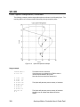
12340
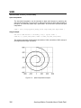
1
12592
12593
12594
12595
12596
2
12848
12849
12850
12851
12852
0
12341
12342
12343
12344
12345
1
12597
12598
12599
12600
12601
2
12853
12854
12855
12856
12857
Filter 1
4
13360
13361
13362
13363
13364
5
13616
13617
13618
13619
13620
6
13872
13873
13874
13875
13876
7
14128
14129
14130
14131
14132
5
13621
13622
13623
13624
13625
6
13877
13878
13879
13880
13881
7
14133
14134
14135
14136
14137
Axis Number
b2 Coefficient
a2 Coefficient
b1 Coefficient
a1 Coefficient
a0 Coefficient
Table 2.1
3
13104
13105
13106
13107
13108
3
13109
13110
13111
13112
13113
4
13365
13366
13367
13368
13369
Digital filter parameters
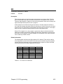
Filter Flags:
Control
Axis Number
Filter Activate
Table 2.2
0
1
2
3
4
5
6
7
786
818
850
882
914
946
978
1010
Digital filter flags
Chapter 2, System Reference
29
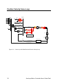
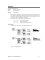
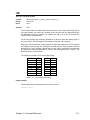
Position Velocity Servo Loop
Primary
Set Point
FFVEL
Velocity
Term
Prof iler
Secondary
Set Point
FFVC
1
Gear
8
Jog
Acceleration
Term
Cam
1
FFACC
s3
Ballscrew
1
PGAIN
Following
Error
IF(KVP==0)
1
s
I
Backlash
Digital
IF(KVP!=0)
1
ILimit
IGAN IDelay
du/dt
Derivative
KVP
Filter
Dac
Torque
Limiter
Dead Hysteresis Output
Zone
1
KVF
1
1
DGAIN
s
I2
1
1
KVI
KVP
ILimit1
Motor
s5
1
s+1
Position Velocity Loop
Position
Encoder
Dual Velocity Loop
FBVEL
1
Sensor
Actual FeedBack Velocity
Calculate_Velocity
Actual FeedBack Position
Figure 2.11
30
Servo loop with Dead Band and Position Velocity Loop
Acroloop Motion Controller User’s Guide Part I
CHAPTER 3
Command Reference
Chapter 3, Command Reference
31
This page intentionally left blank.
32
Acroloop Motion Controller User’s Guide Part I
Command Groups
Axis Limits
ALM
BLM
EXC
IPB
ITB
JLM
MAXVEL
TLM
Set stroke limit ‘A’
Set stroke limit ‘B’
Set excess error band
Set in-position band
Set in-torque band
Set jog limits
Set velocity limits
Set torque limits
Character I/O
CLOSE
INPUT
OPEN
PRINT
Close a device
Receive data from a device
Open a device
Send data to a device
Feedback Control
HSINT
INTCAP
MSEEK
MULT
NORM
PPU
REN
RES
ROTARY
High Speed Interrupt
Encoder capture
Marker seek operation
Set encoder multipliers
Normalize current position
Set axis pulse/unit ratio
Match position with encoder
Reset or preload encoder
Set rotary axis length
Global Objects
ADC
AXIS
DAC
ENC
ENC RD ABS
LIMIT
MASTER
PLS
RATCH
SAMP
CMT
Analog input control
Direct axis access
Analog output control
Quadrature input control
Yaskawa absolute encoder interface
Frequency Limiter
Direct master access
Programmable limit switch
Software ratchet
Data sampling control
Commutator
Chapter 3, Command Reference
33
Command Groups
(continued)
Logic Function
CLR
DWL
IHPOS
INH
MASK
SET
TRG
Clear a bit flag
Delay for a given period
Inhibit on position
Inhibit on bit high or low
Safe bit masking
Set a bit flag
Start move on trigger
Memory Control
CLEAR
DIM
MEM
Clear memory allocation
Allocate memory
Display memory allocation
Nonvolatile
BRESET
ELOAD
ERASE
ESAVE
PBOOT
FLASH
PROM
FIRMWARE
Disable battery backup
Load system parameters
Clear the EEPROM
Save system parameters
Auto-run program
Create user image in flash
Create burner image
Firmware upgrade/backup
Operating System
ATTACH
CONFIG
CPU
DEF
DEFINE
DETACH
DIAG
ECHO
HELP
MODE
PASSWORD
PERIOD
PLC
PROG
REBOOT
SYS
VER
34
Define attachments
Hardware configuration
Display processor loading
Display user defined variables
Define user variables
Clear attachments
Display system diagnostics
Character echo control
Display command list
Binary data formatting
Block uploading programs from board.
Set base system timer period
Switch to a PLC prompt
Switch to a program prompt
Reboot controller card
Return to system prompt
Display firmware version
Acroloop Motion Controller User’s Guide Part I
Command Groups
(continued)
Program Control
AUT
BLK
HALT
LIST
LISTEN
LRUN
NEW
PAUSE
PROGRAM / ENDP
RESUME
RUN
STEP
TROFF
TRON
Turn off block mode
Turn on block mode
Halt an executing program
List a stored program
Listen to program output
Run and listen to a program
Clear out a stored program
Activate pause mode
Mark start and end of program without line numbers.
Release pause mode
Run a stored program
Step in block mode
Turn off trace mode
Turn on trace mode
Program Flow
END
FOR
GOTO
GOSUB
IF / THEN
REM
RETURN
WHILE
End of program execution
Counter loop
Branch to a new line number
Branch to a subroutine
Conditional execution
Program comment
Return from a subroutine
Conditional loop.
Servo Control
DGAIN
DIP
DIN
DWIDTH
DZL
DZU
FBVEL
FFACC
FFVC
FFVEL
FLT
IDELAY
IGAIN
ILIMIT
KVF
KVI
KVP
LOPASS
NOTCH
PGAIN
Set derivative gain
Dead Zone integrator positive value
Dead Zone integrator negative value
Set derivative sample period
Dead Zone inner band
Dead Zone outer band
Set feed back velocity
Set feed forward acceleration
Feedforwad velocity cutoff region
Set feed forward velocity
Digital filter move
Set integral time-out delay
Set integral gain
Set integral anti-windup limit
PV loop feedforward gain
PV loop integral gain
PV loop proportional gain
Setup lopass filter
Setup notch filter
Set proportional gain
Chapter 3, Command Reference
35
Command Groups
(continued)
Setpoint Control
BKL
BSC
CAM
GEAR
HDW
JOG
LOCK
UNLOCK
Set backlash compensation
Ballscrew compensation
Electronic cam
Electronic gearing
Handwheel
Single axis velocity profile
Lock gantry axis
Unlock gantry axis
Transformation
FLZ
OFFSET
ROTATE
SCALE
INVK
Relative program path shift
Absolute program path shift
Rotate a programmed path
Scale a programmed path
Inverse Kinematics
Velocity Profile
ACC
DEC
F
FOV
FVEL
IVEL
JRK
LOOK
MBUF
ROV
SRC
STP
SYNC
TMOV
TOV
VECDEF
VECTOR
VEL
Set acceleration ramp
Set deceleration ramp
Set velocity in units/minute
Set feedrate override
Set final velocity
Set initial velocity
Set jerk parameter (scurve)
Look Ahead mode
Multiple move buffer mode
Set rapid feedrate override
Set external timebase
Set stop ramp
Synchronization mode
Set time based move
Time Override
Define automatic vector
Set manual vector
Set target velocity for a move
Interpolation
CIRCCW
CIRCW
INT
MOV
NURB
SINE
SPLINE
TANG
TARC
36
Counter clockwise circular move
Clockwise circular move
Interruptible move
Define a linear move
NURBs interpolation mode
Sinusoidal move
Spline interploation mode
Tangential move mode
3-D circular interpolation
Acroloop Motion Controller User’s Guide Part I
TRJ
Start new trajectory
Chapter 3, Command Reference
37
Command Cross Reference
The following table shows the commands available for each of the Acroloop Motion
Controller family of boards. This table also indicates at what firmware level a command
has been added above the base firmware level 1.13.03, as well as what firmware level
that the boards have been added.
For the commands that have sub-commands (i.e. ADC), these sub-commands are only
listed when there are different levels of firmware versions and/or board compatiblity.
An “✓ ” indicates that this command is valid for the board.
Command
ACC
ADC
MODE
MAX
SCALE
POS
NEG
GAIN
OFFSET
ON
OFF
ADCX
ALM
ATTACH
AUT
AXIS
BKL
BLK
BLM
BRESET
BSC
CAM
CAM ON TRG
SRC RES
CLEAR
TRGP
ALL OTHERS
CIRCCW
CIRCW
CLEAR
CLOSE
CLR
CMT
CONFIG
CLEAR
IO
XIO
38
ACR12
00
(1.18.02
)
ACR1500
(1.18.02)
✓
✓
✓
✓
✓
✓
✓
✓
✓
✓
✓
✓
X
✓
✓
✓
✓
✓
✓
✓
✓
✓
✓
✓
✓
✓
✓
✓
✓
✓
✓
✓
X
✓
✓
✓
✓
✓
✓
✓
✓
✓
1.18.04
1.18.06
1.18.06
1.18.06 upd12
✓
✓
✓
✓
✓
1.18.06
1.18.06
Version Added
(above 1.13.03)
ACR2000
(1.17.04)
ACR8000
ACR8010
(1.18)
ACR8020
(1.18.06
Upd09)
✓
✓
✓
✓
✓
✓
✓
✓
✓
✓
X
✓
✓
✓
✓
✓
✓
✓
✓
✓
✓
✓
✓
✓
✓
✓
✓
✓
✓
✓
X
✓
✓
✓
✓
✓
✓
✓
✓
✓
✓
✓
✓
✓
✓
✓
✓
✓
✓
✓
X
✓
✓
✓
✓
✓
✓
✓
✓
✓
✓
✓
✓
✓
✓
✓
✓
✓
✓
✓
✓
✓
✓
✓
✓
✓
✓
✓
✓
✓
✓
✓
✓
✓
✓
✓
✓
✓
✓
✓
X
X
X
X
✓
✓
✓
✓
✓
✓
✓
✓
✓
✓
✓
1.18
✓
✓
✓
✓
✓
✓
✓
✓
✓
✓
✓
✓
✓
✓
✓
✓
✓
✓
X
X
✓
✓
✓
X
✓
✓
✓
✓
✓
✓
✓
✓
✓
✓
✓
✓
1.17.03
1.17.03
1.17.03
✓
✓
✓
✓
X
X
✓
✓
✓
✓
✓
✓
✓
✓
✓
✓
✓
✓
1.18
1.18
1.18
1.18.07
✓
X
X
X
Acroloop Motion Controller User’s Guide Part I
Command
IO MODE
IO INPUT
IO OUT
CPU
DAC
DEC
DEF
DEFINE
DETACH
DGAIN
DIAG
DIM
PROG
PLC
P
FIFO
COM1
COM2
LOGGING
MBUF
ACR1500
(1.18.02)
ACR8000
ACR8010
(1.18)
X
X
X
X
X
X
X
X
X
✓
✓
✓
✓
✓
✓
✓
✓
✓
✓
✓
✓
✓
✓
✓
✓
✓
✓
✓
✓
✓
✓
✓
✓
✓
✓
✓
✓
✓
✓
✓
✓
✓
✓
✓
✓
✓
✓
✓
✓
✓
✓
✓
✓
✓
✓
✓
✓
✓
✓
X
✓
✓
✓
✓
✓
✓
✓
✓
✓
✓
✓
✓
✓
✓
✓
✓
✓
✓
✓
✓
✓
✓
✓
✓
✓
✓
✓
X
✓
✓
✓
✓
✓
✓
✓
✓
✓
✓
✓
✓
✓
✓
✓
✓
X
X
X
X
✓
✓
X
X
✓
✓
✓
X
✓
✓
✓
✓
✓
✓
✓
X
✓
✓
✓
✓
✓
✓
✓
✓
✓
✓
✓
✓
✓
✓
✓
✓
✓
✓
✓
✓
✓
✓
✓
✓
✓
✓
✓
✓
✓
✓
✓
✓
✓
✓
✓
✓
✓
✓
✓
✓
✓
✓
✓
✓
✓
✓
✓
✓
✓
✓
✓
✓
✓
✓
✓
✓
✓
✓
✓
✓
✓
✓
✓
✓
✓
✓
✓
✓
✓
X
X
X
X
✓
✓
✓
✓
✓
✓
✓
✓
✓
✓
✓
✓
✓
X
✓
✓
✓
✓
✓
X
✓
✓
✓
✓
✓
X
X
✓
✓
✓
✓
X
✓
✓
✓
✓
✓
X
✓
✓
✓
✓
✓
✓
Version Added
(above 1.13.03)
ACR12
00
(1.18.02
)
1.18.02
1.18.02
1.18.02
X
X
X
✓
✓
✓
1.18.07
1.18.07
✓
✓
✓
✓
✓
✓
✓
✓
✓
✓
✓
✓
✓
✓
✓
✓
✓
✓
✓
✓
✓
✓
✓
✓
✓
✓
✓
✓
✓
✓
✓
✓
✓
✓
X
✓
✓
✓
✓
✓
✓
✓
✓
✓
1.17.03
1.17.03
1.17.03
1.18.00
1.18.06
DIN
DIP
DWIDTH
DWL
DZL
DZU
ECHO
ELOAD
ENC
ENC RD ABS
END
ERASE
ESAVE
EXC
F
FBVEL
FFACC
FFVC
FFVEL
FLASH
LOAD
SAVE
IMAGE
ERASE
1.18.06 upd9
1.18.06 upd9
FLT
FLZ
FOV
FOR / NEXT
FVEL
FSTAT
GEAR
1.18.06
1.18.06 upd9
1.18.06 upd9
1.18.04
1.18.06 upd9
1.17.07
1.18.07
1.18.06 upd9
Chapter 3, Command Reference
ACR2000
(1.17.04)
ACR8020
(1.18.06
Upd09)
39
Command
Version Added
(above 1.13.03)
ACR12
00
(1.18.02
)
ACR1500
(1.18.02)
ACR2000
(1.17.04)
ACR8000
ACR8010
(1.18)
ACR8020
(1.18.06
✓
✓
✓
✓
✓
✓
✓
✓
Upd09)
✓
✓
✓
✓
✓
✓
✓
✓
✓
✓
✓
✓
X
X
✓
✓
GOTO
✓
✓
✓
✓
✓
✓
HALT
✓
✓
✓
✓
✓
✓
HDW
✓
✓
✓
✓
✓
✓
✓
✓
✓
✓
✓
✓
✓
✓
✓
✓
✓
✓
IDELAY
✓
✓
✓
✓
✓
✓
IF / THEN
✓
✓
✓
✓
✓
✓
✓
✓
✓
✓
✓
✓
✓
✓
✓
✓
✓
✓
IHPOS
✓
✓
✓
✓
✓
✓
ILIMIT
✓
✓
✓
✓
✓
✓
INH
✓
✓
✓
✓
✓
✓
INPUT
✓
✓
✓
✓
✓
✓
INT
✓
✓
✓
✓
✓
✓
✓
✓
✓
✓
✓
✓
✓
✓
✓
✓
X
✓
✓
✓
✓
✓
✓
✓
IPB
✓
✓
✓
✓
✓
✓
ITB
✓
✓
✓
✓
✓
✓
IVEL
✓
✓
✓
✓
✓
✓
JLM
✓
✓
✓
✓
✓
✓
JOG
✓
✓
✓
✓
✓
✓
TRG
TRGP
ALL OTHERS
GOSUB
1.18.06 upd12
1.18.06 upd12
HELP
HSINT
IF / ELSE /ENDIF
IGAIN
INTCAP
Fixed Registers
Register Select
INVK
1.16.09
1.18.07
1.18
1.18.07
JRK
✓
✓
✓
✓
✓
✓
KVF
1.18.06 upd9
✓
✓
✓
X
✓
✓
KVI
1.18.06 upd9
✓
✓
✓
X
✓
✓
KVP
1.18.06 upd9
✓
✓
✓
X
✓
✓
LIMIT
✓
✓
✓
✓
✓
✓
LIST
✓
✓
✓
✓
✓
✓
LISTEN
✓
✓
✓
✓
✓
✓
✓
✓
✓
✓
✓
✓
✓
✓
✓
X
✓
✓
LOPASS
✓
✓
✓
✓
✓
✓
LRUN
✓
✓
✓
✓
✓
✓
✓
✓
✓
✓
✓
✓
✓
✓
✓
✓
✓
✓
✓
✓
✓
X
✓
✓
LOCK
LOOK
MASK
1.18.06
1.16.06
MASTER
MAXVEL
40
1.18.04
Acroloop Motion Controller User’s Guide Part I
Command
MBUF
Version Added
(above 1.13.03)
1.18.06
ACR12
00
(1.18.02
)
ACR1500
(1.18.02)
ACR2000
(1.17.04)
ACR8000
ACR8010
(1.18)
ACR8020
(1.18.06
✓
✓
Upd09)
✓
✓
✓
X
MEM
✓
✓
✓
✓
✓
✓
MODE
✓
✓
✓
✓
✓
✓
MOV
✓
✓
✓
✓
✓
✓
MSEEK
✓
✓
✓
✓
✓
✓
MULT
✓
✓
✓
✓
✓
✓
NEW
✓
✓
✓
✓
✓
✓
NORM
✓
✓
✓
✓
✓
✓
✓
✓
✓
✓
✓
✓
NOTCH
NURB
✓
✓
✓
X
✓
✓
OFFSET
✓
✓
✓
✓
✓
✓
OPEN
✓
✓
✓
✓
✓
✓
✓
✓
✓
X
✓
✓
PAUSE
✓
✓
✓
✓
✓
✓
PBOOT
✓
✓
✓
✓
✓
✓
PERIOD
✓
✓
✓
✓
✓
✓
PGAIN
✓
✓
✓
✓
✓
✓
PLC
✓
✓
✓
✓
✓
✓
PLS
✓
✓
✓
✓
✓
✓
PPU
✓
✓
✓
✓
✓
✓
PROG
✓
✓
✓
✓
✓
✓
✓
✓
✓
X
✓
✓
✓
✓
✓
✓
✓
✓
RATCH
✓
✓
✓
✓
✓
✓
REBOOT
✓
✓
✓
✓
✓
✓
REM
✓
✓
✓
✓
✓
✓
REN
✓
✓
✓
✓
✓
✓
RES
✓
✓
✓
✓
✓
✓
RESUME
✓
✓
✓
✓
✓
✓
RETURN
✓
✓
✓
✓
✓
✓
ROTARY
✓
✓
✓
✓
✓
✓
✓
✓
✓
✓
✓
✓
PASSWORD
PROGRAM / ENDP
PROM
1.18.04
1.18.06 Upd 9
1.18.07
ROTATE
ROV
1.17.05
✓
✓
✓
✓
✓
✓
RUN
✓
✓
✓
✓
✓
✓
SAMP
✓
✓
✓
✓
✓
✓
SCALE
✓
✓
✓
✓
✓
✓
SET
✓
✓
✓
✓
✓
✓
✓
✓
✓
✓
✓
✓
✓
X
✓
✓
SINE
SPLINE
1.18.04
Chapter 3, Command Reference
✓
✓
41
ACR12
00
(1.18.02
)
ACR1500
(1.18.02)
SRC
✓
✓
✓
✓
✓
✓
STEP
✓
✓
✓
✓
✓
✓
STP
✓
✓
✓
✓
✓
✓
✓
✓
✓
✓
✓
✓
✓
✓
✓
✓
✓
✓
Command
SYNC
Version Added
(above 1.13.03)
1.18.01
SYS
ACR2000
(1.17.04)
ACR8000
ACR8010
(1.18)
ACR8020
(1.18.06
Upd09)
TANG
1.18.06
✓
✓
✓
X
✓
✓
TARC
1.18.06
✓
✓
✓
X
✓
✓
TLM
✓
✓
✓
✓
✓
✓
TMOV
1.18.01
✓
✓
✓
✓
✓
✓
TOV
1.18.04
✓
✓
✓
✓
✓
✓
TRG
✓
✓
✓
✓
✓
✓
TRJ
✓
✓
✓
✓
✓
✓
TROFF
✓
✓
✓
✓
✓
✓
TRON
✓
✓
✓
✓
✓
✓
UNLOCK
✓
✓
✓
✓
✓
✓
VECDEF
✓
✓
✓
✓
✓
✓
VECTOR
✓
✓
✓
✓
✓
✓
VEL
✓
✓
✓
✓
✓
✓
✓
X
✓
✓
✓
✓
✓
✓
✓
✓
✓
✓
✓
✓
LIMIT
VER
1.18.06
1.17.05
✓
✓
✓
WHILE
1.18.07
✓
42
Acroloop Motion Controller User’s Guide Part I
ACC
Set acceleration ramp
Format:
Group:
Units:
ACC { rate }
Velocity Profile
units / second 2
See also:
DEC, STP, VEL, IVEL, FVEL, PPU
The ACC command sets the master acceleration used to ramp from lower to higher
speeds. Issuing an ACC command with no argument will display the current setting. The
default acceleration ramp is 20000 units / second 2.
The ACC command can be also be used in expressions as follows:
DV1 = ACC + 100
ACC = DEC
Setting ACC to zero disables the acceleration ramp. In cases where the motor needs to
speed up (such as with an FOV command), it will try to do so instantaneously.
The following figure explains the various ACC/DEC/STP usage:
Figure 3.1
ACC/DEC/STP slopes
The following example sets up a acceleration ramp of 10000 units per second 2:
Usage example:
10 ACC 10000
Chapter 3, Command Reference
43
ADC
Analog Input
Format:
Group:
ADC { index } command { data }
Global Objects
See also:
DAC, ENC, AXIS
This command is used along with a second command to control the optional analog input
module. By default, the analog input module converts eight single-ended ±10 volt signals,
using default positive inputs and treating the analog ground pin as the negative input for
all channels. Optionally, the channels can be read as differential pairs by redirecting
positive and negative input signals from any of the eight analog input pins.
Issuing an ADC command without an argument will display the current general setting
for the ADC. Issuing an ADC command to an ADC channel without an argument will
display the current setting for that ADC channel.
The following is a list of valid ADC command combinations:
ADC
ADC
ADC
ADC
ADC
ADC
ADC
ADC
ADC
MODE
MAX
SCALE
POS
NEG
GAIN
OFFSET
ON
OFF
Select the firmware mode (Not available on the ACR2000 board)
Set the number of ADCs (16 Bit ADC only)
Set the physical gain of PGA (16 Bit ADC only)
Select positive channel
Select negative channel
Set analog input gain
Set analog input offset
Enable ADC update
Disable ADC update
The following table outlines parameters related to ADC operation:
ADC
0
1
2
3
4
5
6
7
Input
P6408
P6424
P6440
P6456
P6472
P6488
P6504
P6520
Gain
P6410
P6426
P6442
P6458
P6474
P6490
P6506
P6522
Offset
P6411
P6427
P6443
P6459
P6475
P6491
P6507
P6523
Table 3.1 ADC parameter cross-reference
44
Acroloop Motion Controller User’s Guide Part I
ADC
Analog Input (continued)
Block Diagram:
The following block diagram outlines a single analog input channel:
Figure 3.2
ADC input channel diagram
Chapter 3, Command Reference
45
ADC MODE
(Version 1.18 & Up)
Select the 12-Bit/16-Bit firmware mode
Format:
Group:
Units:
ADC MODE { mode}
Global Objects
none
See also:
ADC, DAC, ENC, AXIS
This command sets the firmware mode for the 12 bit or 16 bit ADC module on the
ACR1200/ACR1500/ACR8000/ACR8010 boards. Issuing an ADC MODE command with
no argument will display the current mode. The default mode is for 12 bit ADC. The mode
is set based on the type of ADC module installed, andis not interchangeable between
modules. The ADC MODE can be saved using the ESAVE command.
Note:
The ACR2000 board only supports the on-board 12 Bit ADC option. 16 Bit ADC is not
available on the ACR2000.
The following table shows the modes:
Mode
0
1
STD 12 Bit ADC
16 Bit ADC
Table 3.2
ADC Mode
The following example sets mode to 16 bits ADC
Usage example:
ADC MODE 1
46
Acroloop Motion Controller User’s Guide Part I
ADC MAX (16 BIT ADC ONLY)
Set the number of ADC Inputs
Format:
Group:
Units:
ADC MAX { number }
Global Objects
none
See also:
ADC, DAC, ENC, AXIS
(Version 1.18 & Up)
This command sets the number of ADC inputs that will be sampled during the servointerrupt period. Issuing an ADC MAX command with no argument will display the current
number of ADC inputs selected. The default number is 8. This command is only for 16 bit
ADC operation. . The ADC MAX can be saved using the ESAVE command.
NOTE: The 12 Bit ADC firmware always samples all 8 ADC inputs.
The following example sets the number of ADC inputs to 5 :
Usage example:
ADC MAX 5
Chapter 3, Command Reference
47
ADC SCALE (16 BIT ADC ONLY)
Set the physical gain of PGA
Format:
Group:
Units:
ADC index SCALE { scale }
Global Objects
none
See also:
ADC, DAC, ENC, AXIS
(Version 1.18 & Up)
Unlike the 12 Bit ADC module, the 16 Bit ADC module has a built-in “Programmable Gain
Amplifier” (PGA). This allows the user to scale the input signal to match four (4) ranges of
input levels. This range can be selected individualy for each channel. This way, the entire
range of 16 bits can be applied to read a +/- 1.25V, +/- 2.5V, +/- 5V, +/- 10V signal.
This command sets the physical gain of the PGA. Issuing an ADC SCALE command with
no argument will display the current scale. The default gain is 1. This command is only
for 16 bits ADC.
The following table shows the relationship between the gain and scale:
Scale
10
5
2.5
1.25
Table 3.3
Gain
1
2
4
8
ADC Scale
The following example sets the physical gain of ADC 1 to 2
Usage example:
ADC 1 SCALE 5
Usage example:
(ACR8020 only & version 1.18.07 &Up)
ADC 12 SCALE 5
48
Acroloop Motion Controller User’s Guide Part I
ADC POS
Select positive channel
Format:
Group:
Units:
ADC index POS { channel }
Global Objects
none
See also:
ADC, DAC, ENC, AXIS
This command sets the positive input for differential analog conversion. Issuing an ADC
POS command with no argument will display the current setting. The default positive
channel is equal to the ADC index number.
The following table shows the relationship between the "channel" and positive input:
Reference appropriate hardware manual for pin-out information.
Channel
0
1
2
3
4
5
6
7
Table 3.4
Pin Name
AIN0
AIN1
AIN2
AIN3
AIN4
AIN5
AIN6
AIN7
ADC positive channels
The following example sets the positive input of ADC 4 to channel 2 :
Usage example:
ADC 4 POS 2
Usage example:
(ACR8020 only & version 1.18.07 &Up)
ADC 12 POS 15
Chapter 3, Command Reference
49
ADC NEG
Select negative channel
Format:
Group:
Units:
ADC index NEG { channel }
Global Objects
none
See also:
ADC, DAC, ENC, AXIS
This command sets the negative input for differential analog conversion. Issuing an ADC
NEG command with no argument will display the current setting. The default negative
channel is 0 for each conversion.
The following table shows the relationship between the "channel" and negative input.
Note that channel 0 attaches to analog ground instead of input 0 like the positive channel
assignment does. Reference appropriate hardware manual for pin-out information.
Channel
0
1
2
3
4
5
6
7
Table 3.5
Pin Name
AGND
AIN1
AIN2
AIN3
AIN4
AIN5
AIN6
AIN7
ADC negative channels
The following example sets the negative input of ADC 4 to channel 3 :
Usage example:
ADC 4 NEG 3
Usage example:
(ACR8020 only & version 1.18.07 &Up)
ADC 12 NEG 14
Setup example for four (4) differential analog inputs:
50
ADC 0 POS 0
ADC 0 NEG 1
DIFFERENTIAL
INPUT #1
P6408
ADC 1 POS 2
ADC 1 NEG 3
DIFFERENTIAL
INPUT #2
P6424
ADC 2 POS 4
ADC 2 NEG 5
DIFFERENTIAL
INPUT #3
P6440
ADC 3 POS 6
ADC 3 NEG 7
DIFFERENTIAL
INPUT #4
P6456
Acroloop Motion Controller User’s Guide Part I
ADC GAIN
Set analog input gain
Format:
Group:
Units:
ADC index GAIN { gain }
Global Objects
volts / input unit
See also:
ADC, DAC, ENC, AXIS
This command sets the software gain for analog conversion. Issuing an ADC GAIN
command with no argument will display the current setting. The default ADC gain value is
10.0 volts / input unit.
When ADC updating is enabled, the readings from the analog input module are internally
scaled to generate a base number of ±1.0 input units. This number is multiplied by the
ADC GAIN setting and then the ADC OFFSET value is added. The result is stored in the
ADC input parameter.
The first example sets the gain on ADC 2 to 9.985 volts = full input unit.
The second example will show 4095 = full scale input.
Usage example:
ADC 2 GAIN 9.985
ADC 2 GAIN 4095
Usage example:
ADC 12 GAIN 5
(ACR8020 only & version 1.18.07 &Up)
ADC OFFSET
Set analog input offset
Format:
Group:
Units:
ADC index OFFSET { offset }
Global Objects
volts
See also:
ADC, DAC, ENC, AXIS
This command sets the software offset for analog conversion. Issuing an ADC OFFSET
command with no argument will display the current setting. The default ADC offset value
is 0.0 volts.
When ADC updating is enabled, the readings from the analog input module are internally
scaled to generate a base number of ±1.0 input units. This number is multiplied by the
ADC GAIN setting and then the ADC OFFSET value is added. The result is stored in the
ADC input parameter.
The following example sets the offset on ADC 2 to 0.012 volts:
Usage example:
ADC 2 OFFSET 0.012
Usage example:
(ACR8020 only & version 1.18.07 &Up)
ADC 12 OFFSET 0.05
Chapter 3, Command Reference
51
ADC ON
Enable ADC update
Format:
Group:
Units:
ADC ON
Global Objects
none
See also:
ADC, DAC, ENC, AXIS
This command enables the update of the analog input module. Note that this command
controls the update of all analog inputs and does not have an "index" operand like the
other ADC commands.
The following example enables ADC updating:
Usage example:
ADC ON
ADC OFF
Disable ADC update
Format:
Group:
Units:
ADC OFF
Global Objects
none
See also:
ADC, DAC, ENC, AXIS
This command disables the update of the analog input module. Note that this command
controls the update of all analog inputs and does not have an "index" operand like the
other ADC commands.
The following example disables ADC updating:
Usage example:
ADC OFF
52
Acroloop Motion Controller User’s Guide Part I
ADCX
Expansion board analog input
Format:
Group:
ADCX
Global Objects
See also:
DAC, ENC, AXIS
This command will display the current setting of the ADC module on 16-axis expansion board.
Usage example:
ADCX
Chapter 3, Command Reference
53
ADCX MODE
(Version 1.18.07 & Up)
Select the 12-Bit/16-Bit firmware mode on expansion board
Format:
Group:
Units:
ADCX MODE { mode}
Global Objects
none
See also:
ADC, DAC, ENC, AXIS
This command sets the firmware mode for the 12 bit or 16 bit ADC module on the
ACR8020 16-axis expansion board. Issuing an ADCX MODE command with no
argument will display the current mode. The default mode is for 12 bit ADC. The mode is
set based on the type of ADC module installed, and is not interchangeable between
modules. The ADCX MODE can be saved using the ESAVE command.
The following table shows the modes:
Mode
0
1
STD 12 Bit ADC
16 Bit ADC
Table 3.2.1
ADCX Mode
The following example sets mode to 16 bits ADC on the expansion board.
Usage example:
ADCX MODE 1
54
Acroloop Motion Controller User’s Guide Part I
ADCX MAX (16 BIT ADC ONLY)
(Version 1.18.07 & Up)
Set the number of ADC Inputs on expansion board
Format:
Group:
Units:
ADCX MAX { number }
Global Objects
none
See also:
ADC, DAC, ENC, AXIS
This command sets the number of ADC inputs that will be sampled during the servointerrupt period on ACR8020, 16-axis expansion board. Issuing an ADCX MAX command
with no argument will display the current number of ADC inputs selected. The default
number is 8. This command is only for 16 bit ADC operation. . The ADC MAX can be
saved using the ESAVE command.
NOTE: The 12 Bit ADC firmware always samples all 8 ADC inputs.
The following example sets the number of ADC inputs to 5 on the expansion board:
Usage example:
ADCX MAX 5
Chapter 3, Command Reference
55
ALM
Set stroke limit 'A'
Format:
Group:
Units:
ALM { axis { value } } { axis { ( high, low ) } } ...
Axis Limits
units
See also:
BLM, PPU
This command sets the command position ( current position) limits monitored by the "A
limit" flags. When the command position of a given axis is within these limits, the
appropriate flag is set. Otherwise, the flag is cleared. For masters, the flag is set if all of
its slaves are within their limits.
Issuing the ALM command to an axis without an argument displays the current positive
and negative limits for that axis. Issuing the command with a single argument sets the
positive limit to "value" and the negative limit to minus "value". Issuing the command with
two arguments sets the positive limit to "high" and the negative limit to "low". The default
for both is 0.0 for all axes.
The following is a table of 'A limit' flags:
MASTER
0
1
2
3
4
5
6
7
Table 3.6
BIT
530
562
594
626
658
690
722
754
AXIS
0
1
2
3
4
5
6
7
BIT
770
802
834
866
898
930
962
994
'A limit' flags
Usage example:
This example sets different positive and negative "A limits" for X, Y and Z axes.
ALM X(10,-10) Y(30,-20) Z(5,0)
56
Acroloop Motion Controller User’s Guide Part I
ATTACH
Define attachments
Format:
Group:
ATTACH { command }
Operating System
See also:
PROG, DETACH
This command is used along with a second command to define how programs, masters,
axes, signals, and feedbacks are attached to one another. Issuing an ATTACH without
the optional "command" will display the attachments to the current program or, if issued
from the system level, all attachments to all programs.
The following is a list of valid ATTACH command combinations:
ATTACH MASTER
ATTACH SLAVE
ATTACH AXIS
Attach master to program.
Attach axis to master.
Attach signal and feedback to axis.
Block Diagram:
The following block diagram illustrates some sample attachments:
Figure 3.3
Sample attachments
Chapter 3, Command Reference
57
ATTACH MASTER
Attach master to program
Format:
Group:
Units:
ATTACH MASTER master
Operating System
none
See also:
ATTACH, DETACH, PROG
This command attaches a master to the current program. Each master has eight internal
slots that serve as attachment points for axes. This command must be issued from a
program prompt. An error will be generated if the master is attached to another program.
Usage example:
This example attaches master 2 to program 0:
PROG0
ATTACH MASTER2
ATTACH SLAVE
Attach slave to axis
Format:
Group:
Units:
ATTACH SLAVE slave AXIS axis "name"
Operating System
none
See also:
ATTACH, DETACH
This command attaches an axis to the current master. The "slave" is an internal slot in
the master that the axis is attached to. The "name" is a one to four character alpha string.
An error will be generated if another axis is already attached to the slave or if the given
axis is attached elsewhere.
Usage example:
This example attaches axes 3 and 4 to the current master as "X" and "Y":
ATTACH SLAVE0 AXIS3 "X"
ATTACH SLAVE1 AXIS4 "Y"
58
Acroloop Motion Controller User’s Guide Part I
ATTACH AXIS
Attach axis to signal and feedback
Format:
Group:
Units:
ATTACH AXIS { axis { position { signal { velocity } } } }
Operating System
none
See also:
ATTACH, CONFIG, FBVEL
This command defines the attachment of position feedback and signal output for a given
axis. If the ATTACH AXIS command is issued without the optional arguments, the
current attachments for all axes are displayed.
The default position attachment is ENC "n", where "n" is equal to the index of the axis.
The following are valid position feedback attachments:
ENC encoder
ADC adc
STEPPER stepper
Quadrature encoder feedback
Analog position feedback
Open loop stepper feedback
The default signal attachment is DAC "n", where "n" is equal to the index of the axis. The
following are valid signal output attachments:
DAC dac
STEPPER stepper
CMT commutator
Analog voltage output
Step and direction output
Sinusoidal/Trapezoidal commutation output
The default velocity attachment is ENC "n", where "n" is equal to the index of the axis.
The velocity of this item ( derivative ) is multiplied by the FBVEL setting and subtracted
from the control signal. The following are valid velocity feedback attachments:
ENC encoder
ADC adc
Quadrature velocity feedback
Analog velocity feedback
Usage example:
This example attaches ENC 5 as position feedback, DAC 6 as signal output, and ADC 7
as velocity feedback on AXIS 4 :
ATTACH AXIS4 ENC5 DAC6 ADC7
Chapter 3, Command Reference
59
AUT
Turn off block mode
Format:
Group:
AUT { PROG number | ALL }
Program Control
See also:
BLK, STEP
This command turns off block mode for the currently selected program by clearing the
program's "block control" bit. To continue normal operation after the AUT command,
issue a STEP command or set the "step request" bit. The STEP command will detect that
"block control" is no longer active and clear the "block mode" bit.
The AUT PROG command will turn off block mode for the corresponding program and
the AUT ALL command will turn off block mode for all programs. These commands can
be issued from anywhere in the system, including programs.
The following example turns off block mode:
Usage example:
AUT
60
Acroloop Motion Controller User’s Guide Part I
AXIS
Direct axis access
Format:
Group:
AXIS index command { data }
Global Objects
See also:
ENC, DAC, MASTER
This command allows direct access to an axis without having to use its name. The axis
does not have to be attached to a master. In general, the "command" argument is any
command or command pair that would normally be followed by an axis name and data.
These commands include those from the axis limits, feedback control, servo control, and
setpoint control groups.
Two other direct axis commands unique to this access mode are:
AXIS ON
AXIS OFF
Enable servo loop
Disable servo loop
These commands turn on and off the servo loop associated with an axis without having
to use the bit flags designated for that purpose. Turning off unnecessary servo loops will
reduce CPU load and improve system performance.
The following example sets the proportional gain on AXIS 3 to 0.001, jogs AXIS 2 to an
absolute jog position of 2.5 units, and disables the AXIS 7 servo loop:
Usage example:
AXIS3 PGAIN 0.001
AXIS2 JOG ABS 2.5
AXIS7 OFF
Chapter 3, Command Reference
61
BKL
Set backlash compensation
Format:
Group:
Units:
BKL { axis { value } } { axis { value } } ...
Setpoint Control
units
See also:
BSC, CAM, GEAR, HDW, JOG
This command sets or displays the backlash compensation of an axis. Backlash is
primarily used to compensate for error introduced by hysteresis in mechanical
gearboxes. Backlash is added to the secondary setpoint when the primary setpoint
moves in the positive direction. If the primary setpoint is not changing, the backlash stays
in its previous state. The backlash offset is used during the summation of the secondary
setpoint.
This compensation is added in one servo update, therefore a large BKL offset will result
in the motor “jerking” a little but the motion at the load should be smooth. For the same
reason this feature might not be usable in a stepper application if the stepper translator
cannot handle pulses too close together.
Issuing a BKL command to an axis without an argument will display the current setting for
that axis. The default backlash is 0.0 for all axes.
Figure 3.4
Backlash compensation
Note: The primary setpoint is the summation of the current position and the total cam,
gear, and jog offsets. The secondary setpoint is the summation of the primary setpoint
and the total ballscrew and backlash offsets. The secondary setpoint is the one that is
actually used by the servo loop.
Usage example:
This example sets backlash compensation for the X axis to 0.0025 units.
BKL X0.0025
62
Acroloop Motion Controller User’s Guide Part I
BLK
Turn on block mode
Format:
Group:
BLK { PROG number | ALL }
Program Control
See also:
AUT, STEP
This command turns on block mode for the currently selected program by setting the
"block control" bit. If there is no master attached, the "block mode" bit is set as soon as
the "block control" bit is detected. Otherwise, the program will feedhold and then set the
"block mode" when the master "in feedhold" is detected.
While in block mode, the program will use the DEC setting as the STP for all moves. This
prevents consecutive moves with STP 0 from coming to abrupt stops. When the program
is taken out of block mode with the AUT command, moves operate normally.
Master cycle start requests are ignored until after the first STEP is issued in block mode.
The BLK PROG command will turn on block mode for the corresponding program and
the BLK ALL command will turn on block mode for all programs. These commands can
be issued from anywhere in the system, including programs.
The following example turns on block mode:
Usage example:
BLK
Chapter 3, Command Reference
63
BLM
Set stroke limit 'B'
Format:
Group:
Units:
BLM { axis { value } } { axis { ( high, low ) } } ...
Axis Limits
units
See also:
ALM, PPU
This command sets the command position ( current Position) limits monitored by the "not
B limit" flags. When the command position of a given axis is outside of these limits, the
appropriate flag is set. Otherwise, the flag is cleared. For masters, the flag is set if any of
its slaves are outside of their limits.
Issuing the BLM command to an axis without an argument displays the current positive
and negative limits for that axis. Issuing the command with a single argument sets the
positive limit to "value" and the negative limit to minus "value". Issuing the command with
two arguments sets the positive limit to "high" and the negative limit to "low". The default
for both is 0.0 for all axes.
The following is a table of 'Not B limit' flags:
MASTER
0
1
2
3
4
5
6
7
Table 3.7
BIT
531
563
595
627
659
691
723
755
AXIS
0
1
2
3
4
5
6
7
BIT
771
803
835
867
899
931
963
995
'Not B limit' flags
Usage example:
This example sets the B limits to ±10 units for the X, Y and Z axes. If the axes are ever all
within their B limits at the same time, the appropriate master flag will clear.
BLM X10 Y10 Z10
64
Acroloop Motion Controller User’s Guide Part I
BRESET
Disable battery backup
Format:
Group:
BRESET
Nonvolatile
See also:
ELOAD, ESAVE, ERASE, PBOOT
ACR8000:
This command disables the battery backup the next time power is removed from the
board. This allows ACR8000 boards to be stored on the shelf without needlessly draining
power from the battery. The next time power is applied to the board, after shutting down
with BRESET in effect, the battery will return to normal and will hold programs during
consecutive power sequences.
Note: Once this command is issued, there is no way to return the battery to normal
operation without removing and then restoring power. Stored programs will be lost.
ACR1200ACR2000/ACR8010:
This command sets the battery backup memory to its default state the next time power is
removed from the board or the board is reset. This allows the ACR1200 / ACR2000 /
ACR8010 battery backed up memory to be cleared to default without physically removing
the battery jumpers on the ACR1200 board, the ACR8010 board or the ACR2000
ACRCOMM board. Reference the ACR1200/ACR2000/ACR8010 Hardware Manual
(ACR2000 ACRCOMM section) for jumper settings to allow the boards to be stored on
the shelf without needlessly draining power from the battery. The next time power is
applied to the board, after shutting down or after resetting the board with BRESET in
effect, the battery backed up memory will return to normal and will hold programs during
consecutive power sequences.
If valid program data has been stored into the Flash, using the FLASH SAVE or FLASH
IMAGE commands, this will overwrite the default conditions of the battery backed up
memory when using BRESET. If the default memory conditions are required, a FLASH
ERASE should be performed before the BRESET command.
Note: Once this command is issued, there is no way to return the battery backed up
memory to normal operation without removing and then restoring power or resetting the
board. Stored programs will be lost.
ACR1500:
This command performs no function on the ACR1500 board.
Usage example:
BRESET
Chapter 3, Command Reference
65
BSC
Ballscrew compensation
Format:
Group:
BSC command { axis { data } } { axis { data } } ...
Setpoint Control
See also:
CAM, BKL, GEAR, HDW, JOG
This command is used along with a second command to initialize and control ballscrew
compensation for an axis. Ballscrew compensation is primarily used to compensate for
nonlinear position error introduced by mechanical ballscrews. Ballscrew commands are
identical to cam commands. Both ballscrews and cams can be active at the same time,
each with different settings and offset tables.
The following is a list of valid ballscrew command combinations. See the corresponding
cam command description for details.
BSC
BSC
BSC
BSC
BSC
BSC
BSC
BSC
BSC
BSC
DIM
SEG
SRC
ON
OFF
SCALE
OFFSET
FLZ
SHIFT
RES
Allocate ballscrew segments
Define ballscrew segment
Redefine ballscrew source
Enable ballscrew output
Disable ballscrew output
Set ballscrew output scaling
Set ballscrew output offset
Set ballscrew input offset
Set incremental ballscrew shift
Transfer ballscrew offset
The main difference between ballscrew and electronic cam is that the default source for a
ballscrew points to the primary setpoint, therefore the BSC SRC command is normally
not required. The primary setpoint is used so that the ballscrew offset is not fed into the
calculation of the ballscrew index, causing an unstable condition.
Note: The primary setpoint is the summation of the current position and the total cam,
gear, and jog offsets. The secondary setpoint is the summation of the primary setpoint
and the total ballscrew and backlash offsets. The secondary setpoint is the one that is
actually used by the servo loop.
66
Acroloop Motion Controller User’s Guide Part I
BSC
Ballscrew compensation (continued)
Figure 3.5
Sample ballscrew table
The following example enables the X axis to use the above ballscrew table:
Usage example:
DIM LA(2)
DIM LA0(9)
LA0(00)=0
LA0(01)=853
LA0(02)=500
LA0(03)=-146
LA0(04)=0
LA0(05)=146
LA0(06)=-500
LA0(07)=-853
LA0(08)=0
BSC DIM X1
BSC SEG X(0,2000,LA0)
BSC ON X
Chapter 3, Command Reference
67
CAM
Electronic cam
Format:
Group:
CAM command { axis { data } } { axis { data } } ...
Setpoint Control
See also:
BKL, BSC, GEAR, HDW, JOG
This command is used along with a second command to control an electronic cam for an
axis. An electronic cam is primarily used as a replacement for a mechanical cam.
Ballscrew commands are identical to cam commands. Both ballscrews and cams can be
active at the same time, each with different settings and offset tables.
The following is a list of valid cam command combinations:
CAM
CAM
CAM
CAM
CAM
CAM
CAM
CAM
CAM
CAM
CAM
DIM
SEG
SRC
ON
OFF
SCALE
OFFSET
FLZ
SHIFT
RES
ON TRG
Allocate cam segments
Define cam segment
Redefine cam source
Enable cam output
Disable cam output
Set cam output scaling
Set cam output offset
Set cam input offset
Set incremental cam shift
Transfer cam offset
Enable CAM ON from external trigger
Cam uses an arbitrary encoder position to generate an index into a table of offset values.
If this index falls between two table entries, the cam offset is linearly interpolated
between the entries. This offset is then scaled, shifted by the output offset, and then
multiplied by the PPU for the given axis.
A cam table can be composed of more than one segment with each segment having
different distances between table entries. The data for each segment of the table resides
in separate longint arrays, possibly of different sizes. This allows some parts of the table
to be defined coarsely and others to be defined in more detail.
The table index automatically tracks which segment it is in and where it is within that
segment. It also wraps around if it goes off either end of the table. The wraparound point
is determined by the total length of the table which is equal to the summation of the
individual segment lengths.
Note: The primary setpoint is the summation of the current position and the total cam,
gear, and jog offsets. The secondary setpoint is the summation of the primary setpoint
and the total ballscrew and backlash offsets. The secondary setpoint is the one that is
actually used by the servo loop.
68
Acroloop Motion Controller User’s Guide Part I
CAM
Electronic cam (continued)
Figure 3.6
Sample cam table
The following example enables the X axis to use the above cam table with encoder
number 4 as the input source:
Usage example:
DIM LA(2)
DIM LA0(9)
LA0(00)=0
LA0(01)=73
LA0(02)=250
LA0(03)=427
LA0(04)=500
LA0(05)=427
LA0(06)=250
LA0(07)=73
LA0(08)=0
DIM LA1(5)
LA1(00)=0
LA1(01)=0
LA1(02)=-500
LA1(03)=-500
LA1(04)=0
CAM
CAM
CAM
CAM
CAM
DIM X2
SEG X(0,500,LA0)
SEG X(1,1000,LA1)
SRC X4
ON X
Note:
The CAM SRC command must be issued AFTER the cam segments have been
defined. Improper operation may result from designating the CAM SRC first.
Issuing just the CAM command will display the current setting of a cam and can
be used even if the cam is currently active. The example below shows the list
Chapter 3, Command Reference
69
Usage example:
P00>CAM X
CAM FLZ X0
CAM OFFSET X0
CAM SCALE X1
CAM DIM X4
CAM SEG X (0, 2000,
CAM SEG X (1, 2000,
CAM SEG X (2, 2000,
CAM SEG X (3, 2000,
CAM SHIFT X0
CAM SRC X P12802
CAM ON X
LA1)
LA3)
LA1)
LA0)
CAM Cycles
Axis parameter “ CAM Cycles “ can be set to run so many CAM cycles. Says this
parameter is set to 3, then the CAM will run for 3 times and then automatically turn itself
off. The defalut value is zero which means that the CAM will run forever unless the user
turns it off.
Example 1
P12400 = 3
CAM ON X TRG (0,0)
:
CAM ON X TRG (0,0)
:REM The CAM
will run 3 times
:REM The CAM
will run 3 times
The cam source is automatically reset when ussing the triggerd CAM
Example 2
P12400 = 3
CAM SRC X RES
CAM ON X :REM The CAM will 3 times
CAM SRC X RES
CAM ON X :REM The CAM will 3 times
The cam source is explicitly reset and the source should not be moving before the cam is
trun on otherwise the CAM will not begin from the start.
CAM Velocity Smooth
Axis Parameter “CAM Velocity Smooth” is used to smooth out the CAM velocity that is
used for the feed forward control. The Default value is 10, which means that the velocity
is averaged on 10 samples to take away the jitter in the velocity term. The user can
change this value to suite his application, however it should be changed before turning
the CAM ON.
70
Acroloop Motion Controller User’s Guide Part I
CAM CLEAR
Clear the CAM setting
Format:
Group:
CAM CLEAR {axis}
set point control
See also:
CAM
This command is used to clear the current setting of a cam. This command will
turn off the cam and initialize all the cam variables to the default values. It can be
used even if the cam is currently active.
NOTE: The memory allocated to the CAM DIM command will still be there and
so will be the number of segments and their respective lengths. The cam can not
be re-dimensioned by this command. If needed one has to use CLEAR ALL
command to clear all the memory.
Usage example:
CAM CLEAR Y
Chapter 3, Command Reference
71
CAM DIM
Allocate cam segments
Format:
Group:
CAM DIM { axis segments } { axis segments } ...
Setpoint Control
See also:
CAM, BKL, BSC, GEAR, HDW, JOG, DIM, CLEAR
This command allocates working space for a cam. The cam must be dimensioned before
it can be initialized. This is in addition to the dimensioning done for the actual
arrays attached to the cam segments. Newly dimensioned cams have no source defined
for them, ballscrews point to the primary setpoint by default.
A cam can be composed of more than one segment with each segment having different
distances between table entries. This allows some parts of the table to be defined
coarsely and others to be defined in more detail.
The memory allocated by the CAM DIM command is a base of 52 bytes of working space
plus an additional 24 bytes per defined segment.
Once a cam has been allocated, it can not be redimensioned to a different size without
first doing a CLEAR to erase all dimensioning. This will also deallocate any dimensioned
user variables or cams. Do not allocate any more segments than are required by the
application.
The following example allocates two cam segments for the X axis and a single segment
for the Y axis:
Usage example:
CAM DIM X2 Y1
72
Acroloop Motion Controller User’s Guide Part I
CAM SEG
Define cam segment
Format:
Group:
CAM SEG { axis ( segment , length , array_name ) } ...
Setpoint Control
Units:
segment
length
array_name
See also:
CAM, BKL, BSC, GEAR, HDW, JOG, DIM, CLEAR
= none
= input units
= none
This command defines the segments that were allocated with the CAM DIM command.
The "segment" is a number from 0 to segments-1 and indicates which segment is being
defined. The "length" parameter defines the total length of the given segment. The
"array_name" is the name of the longint array where the data points are to be stored.
An error will occur if the cam has not been allocated with the CAM DIM command.
A cam can be composed of more than one segment with each segment having different
distances between table entries. This allows some parts of the table to be defined
coarsely and others to be defined in more detail.
The following internal formulas are modified by the CAM SEG information:
distance between entries
total length of the cam
= segment length / ( number of table entries - 1 )
= sum of segment lengths
Note that this information can be altered while the cam is enabled, allowing the
replacement of segments or the changing segment lengths on the fly.
The following example defines the segment 1 of the X axis cam as being 10000 units
long and pointing to longint array LA0 for its data:
Usage example:
CAM SEG X(1,10000,LA0)
Issuing just CAM SEG command will display cam segment data.
Usage example:
P00>CAM SEG X
Seg_0 (0, 100, 500, 500)
Seg_1 (500, 1500, 2000, 3000)
Seg_2 (3000, 2500, 1000, 500)
Seg_3 (500, 500, 100, 0)
Chapter 3, Command Reference
73
CAM SRC
Redefine cam source
Format:
Group:
Units:
CAM SRC axis sourcedef { axis sourcedef } ...
Setpoint Control
none
See also:
SRC
This command specifies the source for the input of a cam. See the SRC command for the
definition of the "sourcedef" argument.
This command sets a pointer to a memory area that is used to generate an index into the
cam table. Cams do not have a default source assigned to them, ballscrews point to the
primary setpoint by default. An error will occur if the cam has not been allocated with the
CAM DIM command.
The following example sets the source of the X axis to encoder 3 and the source of the Y
axis to the current position of AXIS1 ( note that the parameter P12544 is not enclosed in
parentheses ) :
Usage example:
CAM SRC X3 Y P12544
74
Acroloop Motion Controller User’s Guide Part I
CAM SRC RES
Reset the cam source
Format:
Group:
See also:
CAM SRC {axis} RES
Setpoint Control
SRC
This command resets the source the for the input of a cam. Usually it will be used when
the cam is off and the source needs to be reset to a certain value.
Usage example:
CAM SRC X RES
CAM SRC X RES 100
Chapter 3, Command Reference
:REM Reset source of X to zero
:REM Reset source to 100
75
CAM ON
Enable cam output
Format:
Group:
CAM ON { axis } { axis } ...
Setpoint Control
See also:
CAM, BKL, BSC, GEAR, HDW, JOG
This command enables cam output for the designated axes. An error will be returned if
the cam has not been allocated with the CAM DIM command.
NOTE: Once CAM is enabled, it will stay enabled unless CAM Parameter “CAM
CYCLES” is set to a value other than zero.
The following example enables the X, Y, and Z axis cams:
Usage example:
CAM ON X Y Z
CAM OFF
Disable cam output
Format:
Group:
CAM OFF { axis } { axis } ...
Setpoint Control
See also:
CAM, BKL, BSC, GEAR, HDW, JOG
This command disables cam output for the designated axes. An error will be returned if
the cam has not been allocated with the CAM DIM command.
The following example disables the X and Y axis cams:
Usage example:
CAM OFF X Y
76
Acroloop Motion Controller User’s Guide Part I
CAM SCALE
Set cam output scaling
Format:
Group:
Units:
CAM SCALE { axis { scale } } { axis { scale } } ...
Setpoint Control
none
See also:
CAM, BKL, BSC, GEAR, HDW, JOG
This command sets or displays the cam output scaling of an axis. After the cam table and
index are used to interpolate an initial offset value, the value is multiplied by the cam
output scaling factor and then shifted by the cam output offset. This number is then
multiplied by the PPU of the given axis.
Issuing a CAM SCALE command to an axis without an argument will display the current
setting for that axis. An error will be returned if the cam has not been allocated with the
CAM DIM command. The default cam output scaling is 1.0 for all axes.
The following example scales the X axis cam offset by 50 percent:
Usage example:
CAM SCALE X0.5
CAM OFFSET
Set cam output offset
Format:
Group:
Units:
CAM OFFSET { axis { scale } } { axis { scale } } ...
Setpoint Control
output units
See also:
CAM, BKL, BSC, GEAR, HDW, JOG
This command sets or displays the cam output offset of an axis. After the cam table and
index are used to interpolate an initial offset value, the value is multiplied by the cam
output scaling factor and then shifted by the cam output offset. This number is then
multiplied by the PPU of the given axis.
Issuing a CAM OFFSET command to an axis without an argument will display the current
setting for that axis. An error will be returned if the cam has not been allocated with the
CAM DIM command. The default cam output offset is 0.0 for all axes.
The following example shifts the X axis cam table output 500 units:
Usage example:
CAM OFFSET X500
Chapter 3, Command Reference
77
CAM FLZ
Set cam input offset
Format:
Group:
Units:
CAM FLZ { axis { offset } } { axis { offset } } ...
Setpoint Control
input units
See also:
CAM, BKL, BSC, GEAR, HDW, JOG
This command sets or displays the cam input offset of an axis. The cam input offset is
added to the cam table index before it is used to calculate the actual table index. This is
used to shift the zero of the table to the location of the input offset.
Issuing a CAM FLZ command to an axis without an argument will display the current
setting for that axis. An error will be returned if the cam has not been allocated with the
CAM DIM command. The default cam input offset is 0.0 for all axes.
The following example shifts the X axis cam table index by 250 units:
Usage example:
CAM FLZ X250
CAM SHIFT
Set incremental cam shift
Format:
Group:
Units:
CAM SHIFT { axis { offset } } { axis { offset } } ...
Setpoint Control
units
See also:
CAM, BKL, BSC, GEAR, HDW, JOG
This command sets the incremental cam shift. The first entry of one cam segment is
normally equal to the last entry of the previous segment. In cases where this is not true,
the cam is considered to be incremental. The starting "shift" for all cams is 0.0. Issuing a
CAM SHIFT with no argument will display the current reading.
Whenever an incremental cam crosses a segment boundary, the difference between the
two entries is used to adjust the cam shift. The cam shift is added to the interpolated
offset to generate the actual cam offset. If the total of all segment boundary shifts is not
equal to zero, the overall pattern will be offset by that amount each cycle. Crossing cam
segment boundaries backwards will also adjust the cam shift.
The following example clears the X axis cam shift:
Usage example:
CAM SHIFT X0
78
Acroloop Motion Controller User’s Guide Part I
CAM RES
Transfer cam offset
Format:
Group:
Units:
CAM RES { axis { offset } } { axis { offset } } ...
Setpoint Control
units
See also:
CAM, BKL, BSC, GEAR, HDW, JOG
This command either clears or preloads the cam offset of a given axis and adds the
difference to the current position. This command will also clear out any cam shift that
may have been built up by an incremental cam. The default "offset" argument is zero.
The current position and cam offset are adjusted according to the following formula:
current_position = current_position + cam_offset - offset
cam_offset = offset
When a cam is turned off, the offset remains in the cam offset parameter. The CAM RES
command can be used to transfer the offset into the current position where it can be used
as part of a normal move.
The following example transfers the X axis cam offset into the current position:
Usage example:
CAM RES X
Chapter 3, Command Reference
79
CAM ON TRG
(Version 1.18.04 & Up)
Enable external source trigger CAM
Format:
Group:
CAM ON {axis} TRG(mode,capture_register)
Setpoint Control
See also:
CAM, HDW, BSC, BKL, GEAR, JOG
This command is not valid for the ACR8000.
This command arms the loaded CAM to begin when an externally sourced trigger occurs.
The latency error is 1 microsecond. The mode parameter and hardware capture register
information for the CAM ON TRG is the same as those used in the INTCAP command.
NOTE: It is recommended that the CAM source should be attached before the source
starts to move
The following example enables or starts the Y axis cam when triggered by rising primary
marker of encoder 0.
Usage example:
CAM SRC Y 0
CAM ON Y TRG(0,0)
If the CAM needs to be turned off and armed again then issue the following commands
CAM OFF Y
CAM RES Y
CAM ON Y TRG(0,0)
80
Acroloop Motion Controller User’s Guide Part I
CAM ON TRGP
Enable external trigger CAM
(Version 1.18.06 Update 09)
Format:
Group:
CAM ON {axis} TRG(mode,capture_register)
Setpoint Control
See also:
CAM, HDW, BSC, BKL, GEAR, JOG
This command is not valid for the ACR8000.
This command is same as the CAM ON TRG, except that the cam source can be any P
parameter. In this case the capture register value is not used since the cam source value
is different than the capture register value. This is less precise than the CAM ON TRG
and the worse case error can be one servo period.
The following example enables or starts the Y axis cam when triggered by rising primary
marker of encoder 0.
Usage example:
CAM SRC Y P12288
CAM ON Y TRGP(0,0)
If the CAM needs to be turned off and armed again then issue the following commands
CAM OFF Y
CAM RES Y
CAM ON Y TRGP(0,0)
Chapter 3, Command Reference
81
CIRCCW
(Version 1.18 04 Upd 1 & Up)
2-Dimensional Counter Clockwise Circle
Format:
Group:
See also:
CIRCCW {axis (target, center) axis(target, center)}
Interpolation
SINE, CIRCW
This command generates a circular profile on the plane defined by the two selected axes.
The command can be used to generate any counter clockwise arc between 0 to 360
degree.
target
center
position at the end of the move ( in units )
center of the circle to by drawn ( in units )
The following formula is used to calculate the start point of the arc. The profiler will
always start from this point and end at the target point. If the current axis position
does not match this start point then the axis will jump to the start point.
theta = start angle of arc
radius = radius of the arc = target - center
xstart = xcenter + radius * cos(theta)
ystart = ycenter + radius * sin(theta)
The start point of the arc is derived from the above calculations. If the current position is
not equal to the calculated start point, the arc must be proceeded with a move to (xstart,
ystart) or the axes will try to jump immediately to that point.
Usage example:
CIRCCW X ((LV1),(LV2) ) Y ((LV3),(LV4) )
CIRCCW X (59.078, -59) Y (-75.576, -100)
CIRCCW X/(110.23, 134) Y (-152.309, -80)
82
Variable
target
and center.
Absolute
target
and center.
X-axis
has
incremental target
and center
Acroloop Motion Controller User’s Guide Part I
CIRCW
(Version 1.18 04 Upd 1 & Up)
2-Dimensional Clockwise Circle
Format:
Group:
See also:
CIRCCW {axis (target, center) axis(target, center)}
Interpolation
SINE, CIRCCW
See the CIRCCW command for details, the only difference is that this draws clockwise
arc instead of counter clockwise arcs.
Usage example:
CIRCW X ((LV1),(LV2) ) Y ((LV3),LV4) )
CIRCW X (59.078, -59) Y (-75.576, -100)
CIRCW X/(110.23, 134) Y (-152.309, -80)
Chapter 3, Command Reference
Variable target and
center
Absolute target and
center
X-axis has
incremental target
and center
83
CLEAR
Clear memory allocation
System Level Formats:
CLEAR
CLEAR FIFO
CLEAR COM1
CLEAR COM2
Program Level Format:
CLEAR
Group:
Memory Control
See also:
DIM, MEM
This command will free memory that was dimensioned for programs, variables, and
arrays and data logging. This command behaves differently depending on whether the
communication port is at the system or program level.
From the system level, the CLEAR command will free the memory allocated to all
programs. The programs must be empty for this to work. If the programs are not empty,
an error will be given. After clearing the programs, the DIM command must be used to
allocate memory for the programs as required.
Stream buffers may also be returned to their default 256 byte storage area using the
CLEAR command from the system level. After the stream is redimensioned and ready for
use, the appropriate “Stream Redimensioned” flag will be set.
From the program level, or within a running program, the CLEAR command frees the
memory allocated to local variables and arrays.
Usage example:
SYS
HALT ALL
NEW ALL
DETACH ALL
CLEAR
84
Acroloop Motion Controller User’s Guide Part I
CLOSE
Close a device
Format:
Group:
CLOSE #device
Character I/O
See also:
PRINT, INPUT, OPEN
This command closes a device. The valid range for "device" is 0 to 3. Each program has
it's own device #0 which is used as its default device. Devices #1 through #3 are boardwide system resources that can be closed from within any program or from any system or
program prompt.
When a device is opened, the operating system attached to that device enters an idle
state, allowing incoming characters to be used by a program instead of being interpreted
as commands. When the device is closed, the device will enter its auto-detect mode as if
it were starting from power-up.
Usage example:
CLOSE #1
Chapter 3, Command Reference
85
CLR
Clear a bit flag
Format:
Group:
CLR index
Logic Function
See also:
SET, INH, BIT
This command clears the specified bit flag. This flag can either be a physical output or an
internal bit flag.
The following example will clear output 32:
Usage example:
10 CLR 32
86
Acroloop Motion Controller User’s Guide Part I
CMT
Commutation
(Version 1.18 & Up)
Format:
Group:
CMT index command {data} {command {data}}…
Global Objects
See also:
ATTACH,DAC,ENC,AXIS
The commutation is available on ACR1200, ACR1500, ACR8010 ACR2000 and
ACR8020 version 1.18 and above only. Commutation is not available on the ACR8000
Board.
The commutator takes the output of the servo loop as its input and performs
sinusoidal/trapezoidal computation according to the shaft position. Each commutator
(CMT) object uses two dac outputs to generate sinusoidal or trapezoidal signals to
command “phased sine” input type servo amplifiers. Additionally, the commutator may
use an extra encoder input to read hall effect channels for each moter. Therefore, the
ACR8010 can control a maximum of four axis, if they are all being commutated. The
ACR1500 and ACR2000 can do a maximum of two (2) axis. This is because the
ACR8010 and the ACR2000 have a maximum of eight (8) and four (4) dacs, respectively.
The ACR1200, with a maximum of two (2) dac outputs, can be configured for a single
axis of commutation.
By default each commutator starts up in trapezoidal mode and switches over to
sinusoidal mode at the occurance of the first marker pulse of the feedback encoder. The
user can choose to force the system to stay in the trapezoidal mode using the CMT
MODE command. The user can also choose to start the commutator without hall signals.
In Hall-less start up mode the moter shaft will jerk . Once the shaft is locked to a known
position the commutator will switch over to sinusoidal mode.
The following is a list of valid CMT command combinations:
CMT ON
CMT OFF
CMT ENC
CMT DAC
ENC
DAC
CMT MODE
CMT ANG
CMT SHIFT
CMT PPR
CMT ERPMR
CMT
CMT
CMT
CMT
CMT
CMT
MAX RPM
MAX AMP
HSEEK CAP
LOCK AMP
LOCK RANGE
LOCK COUNT
Turn on commutator
Turn off commutator
Set source of commutation position feedback and hall
signal
Set sources of output signals
Set commutation mode
Set phase difference between the two CMT output
signals
Set the phase offset
Set the encoder line per revolution of the motor
Set Electrical revolution per mechanical revolution or
poles_pair.
Set maximum speed
Set maximum peak current
Set up parameter ERPMR and SHIFT automatically.
Set current amplitude for hall-less start up
Set lock position accuracy
Set lock position accuracy
Chapter 3, Command Reference
87
CMT
Commutation (continued)
(Version 1.18 & Up)
Issuing a CMT command with an index, but without an additional command, will display
the current setting of the commutator.
The example assumes CMT0 as output of AXIS0 (X) and ENC0 as position feedback on
AXIS0 as follows:
ATTACH AXIS0 ENC0 CMT0 ENC0
Usage example1:
10 CMT0 ENC0 ENC1
20 CMT0 MODE 8
30 CMT0 ANG 120
40 CMT0 DAC0 DAC1
50 CMT0 SHIFT 100
60 CMT0 PPR 1024
70 CMT0 ERPMR 2
80 CMT0 MAX RPM 4500
90 CMT0 MAX AMP 10
100 CMT0 ON
Usage example2:
10 CMT0 MODE 1
20 CMT0 ON
30 CMT0 HSEEK 0.5 CAP2
Usage example3:
10 CMT0 DAC0 DAC1
20 CMT0 ENC0 ENC0
20 CMT0 PPR 1024
30 CMT0 MODE 2
40 CMT0 MAX RPM 4500
50 P16406 = 2
60 CMT0 MAX AMP 5
70 CMT0 ERPMR 2
80 CMT0 LOCK COUNT 200
90 CMT0 LOCK RANGE 5
100 CMT0 LOCK AMP .5
88
Acroloop Motion Controller User’s Guide Part I
CMT
Commutation (continued)
(Version 1.18 & Up)
Related commutation Flags:
Flag Parameter
CMT Flags
CMT Commutator ON
CMT Sinusoidal ON
CMT Motor Overspeed
CMT Encoder Fault
CMT EncCheck Disable
CMT Following Error
Reserved
Reserved
Spare
Spare
Spare
Spare
Spare
Spare
Spare
Spare
CMT Pseek Enable
Spare
Spare
Spare
Spare
Spare
Spare
Spare
Spare
Spare
Spare
Spare
Spare
Spare
Spare
Spare
Bit
Index
0
1
2
3
4
5
6
7
8
9
10
11
12
13
14
15
16
17
18
19
20
21
22
23
24
25
26
27
28
29
30
31
Chapter 3, Command Reference
4208
4209
4210
4211
4212
4213
4214
4215
0
3584
3585
3586
3587
3588
3589
3590
3591
3592
3593
3594
3595
3596
3597
3598
3599
3600
3601
3602
3603
3604
3605
3606
3607
3608
3609
3610
3611
3612
3613
3614
3615
1
3616
3617
3618
3619
3620
3621
3622
3623
3624
3625
3626
3627
3628
3629
3630
3631
3632
3633
3634
3635
3636
3637
3638
3639
3640
3641
3642
3643
3644
3645
3646
3647
2
3648
3649
3650
3651
3652
3653
3654
3655
3656
3657
3658
3659
3660
3661
3662
3663
3664
3665
3666
3667
3668
3669
3670
3671
3672
3673
3674
3675
3676
3677
3678
3679
CMT Number
3
4
3680
3712
3681
3713
3682
3714
3683
3715
3684
3716
3685
3717
3686
3718
3687
3719
3688
3720
3689
3721
3690
3722
3691
3723
3692
3724
3693
3725
3694
3726
3695
3727
3696
3728
3697
3729
3698
3730
3699
3731
3700
3732
3701
3733
3702
3734
3703
3735
3704
3736
3705
3737
3706
3738
3707
3739
3708
3740
3709
3741
3710
3742
3711
3743
5
3744
3745
3746
3747
3748
3749
3750
3751
3752
3753
3754
3755
3756
3757
3758
3759
3760
3761
3762
3763
3764
3765
3766
3767
3768
3769
3770
3771
3772
3773
3774
3775
6
3776
3777
3778
3779
3780
3781
3782
3783
3784
3785
3786
3787
3788
3789
3790
3791
3792
3793
3794
3795
3796
3797
3798
3799
3800
3801
3802
3803
3804
3805
3806
3807
7
3808
3809
3810
3811
3812
3813
3814
3815
3816
3817
3818
3819
3820
3821
3822
3823
3824
3825
3826
3827
3828
3829
3830
3831
3832
3833
3834
3835
3836
3837
3838
3839
89
CMT
Commutation (continued)
(Version 1.18 & Up)
CMT Commutator ON
r
This flag is set when the commutator is ON.
CMT Sinusoidal ON
r
This flag is set when the commutator is in sinusoidal
mode.
CMT Motor
Overspeed
r
This flag is set if overspeed is detected. The
commutator will be turned off if this bit is set.
CMT Encoder Fault
r
This flag is set if an encoder fault is detected . The
commutator will be turned off if this bit is set and the
CMT ENCCHECK DISABLE flag is reset.
r/w
When this flag is reset, the commutator will be turned
off if an encoder fault is detected.
When this flag is set, the commutator won’t be turned
off even though an encoder fault is detected
CMT Following Error
r
This flag is set if following error exceeds
MaxFollowingERR. The commutator will be turned off
if this be is set.
CMT Pseek Enable
r/w
If this flag is set and the commutator is turned on at
mode 2, at the ccurance of the first marker pulse of
the feedback encoder, parameter PhaseMarkerOffset
will be set by firmware and this flag will be cleared.
CMT EncCheck
Disable
r = read, w = write
90
Acroloop Motion Controller User’s Guide Part I
CMT
Commutation (continued)
(Version 1.18 & Up)
Related commutation parameters:
CMT Parameters
FeedBackEncoder
AngleBetweenPhases
EncoderShaftPosition
PhaseADacChannel
PhaseBDacChannel
PulsePerRevolution
PhaseAADCChannel
PhaseBADCChannel
PhaseMarkerOffset
ElecRevPerMechRev
HallEffectChannel
PhaseLockCount
MaxEncDelta
Reserved
MaxFollowingErr
CommutationRegion
CommandSignal
Reserved
SineIndexPerEncCount
Reserved
LookedUpPhaseASine
LookedUpPhaseBSine
CommandCurrentScale
FeedbackCurrentScale
PhaseASignal
PhaseBSignal
PhaseAOffset
PhaseBOffset
PhaseAGain
PhaseBGain
MaxMotorRPM
MaxMotorCurrent
Reserved
AverageVelocity
LockCurrent
Reserved
Reserved
Reserved
Reserved
Reserved
LONG
LONG
LONG
LONG
LONG
LONG
LONG
LONG
LONG
LONG
LONG
LONG
LONG
LONG
LONG
LONG
FP32
FP32
FP32
FP32
FP32
FP32
FP32
FP32
FP32
FP32
FP32
FP32
FP32
FP32
FP32
FP32
FP32
FP32
FP32
FP32
FP32
FP32
FP32
FP32
0
1
2
16384
16385
16386
16387
16388
16389
16390
16391
16392
16393
16394
16395
16396
16397
16398
16399
16400
16401
16402
16403
16404
16405
16406
16407
16408
16409
16410
16411
16412
16413
16414
16415
16416
16417
16418
16419
16420
16421
16422
16423
16640
16641
16642
16643
16644
16645
16646
16647
16648
16649
16650
16651
16652
16653
16654
16655
16656
16657
16658
16659
16660
16661
16662
16663
16664
16665
16666
16667
16668
16669
16670
16671
16672
16673
16674
16675
16676
16677
16678
16679
16896
16897
16898
16899
16900
16901
16902
16903
16904
16905
16906
16907
16908
16909
16910
16911
16912
16913
16914
16915
16916
16917
16918
16919
16920
16921
16922
16923
16924
16925
16926
16927
16928
16929
16930
16931
16932
16933
16934
16935
Chapter 3, Command Reference
CMT Number
3
4
17152
17153
17154
17155
17156
17157
17158
17159
17160
17161
17162
17163
17164
17165
17166
17167
17168
17169
17170
17171
17172
17173
17174
17175
17176
17177
17178
17179
17180
17181
17182
17183
17184
17185
17186
17187
17188
17189
17190
17191
17408
17409
17410
17411
17412
17413
17414
17415
17416
17417
17418
17419
17420
17421
17422
17423
17424
17425
17426
17427
17428
17429
17430
17431
17432
17433
17434
17435
17436
17437
17438
17439
17440
17441
17442
17443
17444
17445
17446
17447
5
6
7
17664
17665
17666
17667
17668
17669
17670
17671
17672
17673
17674
17675
17676
17677
17678
17679
17680
17681
17682
17683
17684
17685
17686
17687
17688
17689
17690
17691
17692
17693
17694
17695
17696
17697
17698
17699
17700
17701
17702
17703
17920
17921
17922
17923
17924
17925
17926
17927
17928
17929
17930
17931
17932
17933
17934
17935
17936
17937
17938
17939
17940
17941
17942
17943
17944
17945
17946
17947
17948
17949
17950
17951
17952
17953
17954
17955
17956
17957
17958
17959
18176
18177
18178
18179
18180
18181
18182
18183
18184
18185
18186
18187
18188
18189
18190
18191
18192
18193
18194
18195
18196
18197
18198
18199
18200
18201
18202
18203
18204
18205
18206
18207
18208
18209
18210
18211
18212
18213
18214
18215
91
CMT
Commutation (continued)
92
(Version 1.18 & Up)
FeedBackEncoder
r/w
The feedback encoder channel.
AngleBetweenPhases
r/w
The phase difference between phase B and Phase A
EncoderShaftPosition
r
Feedback encoder position. This parameter will be
reset by the marker pulse of the encoder.
PhaseADacChannel
r/w
Phase A DAC channel.
PhaseBDacChannel
r/w
Phase B DAC channel.
PulsePerRevolution
r/w
Raw encoder counts (without multiplier) per
revolution.
PhaseAADCChannel
r/w
Phase A ADC channel.
PhaseBADCChannel
r/w
Phase B ADC channel.
PhaseMarkerOffset
r/w
This parameter applies to sinusoidal mode only. The
commutator uses the sum of the current feedback
encoder counts and this parameter to calculate the
index of the sinusoidal look up table.
ElecRevPerMechRev
r/w
Electrical cycles per mechanical revolution
HallEffectChannel
r/w
Hall effect signals channel. This parameter should
equal to FeedBackEncoder if hall-less commutation
mode is used.
PhaseLockCount
r/w
This parameter applies to hall-less commutation only.
The commutation axis is consider to be locked if the
difference of two consecutive reading of the feedback
encoder is less than MaxEncDelta for
PhaseLockCount of consecutive servo periods.
MaxEncDelta
r/w
This parameter applies to hall-less commutation only.
The commutation axis is consider to be locked if the
difference of two consecutive reading of the feedback
encoder is less than MaxEncDelta for
PhaseLockCount of consecutive servo periods.
MaxFollowingErr
r/w
Maximium following error. If the following error is
greater than this parameter the commutator will be
turned off.
CommutationRegion
r/w
Hall effect signal reading.
Acroloop Motion Controller User’s Guide Part I
CMT
Commutation (continued)
(Version 1.18 & Up)
CommandSignal
r
Output of servo loop.
SineIndexPerEncCount
r
Feedback encoder position. This parameter will be
reset by the marker pulse of the encoder.
LookedUpPhaseASine
r
Phase A SINE value.
LookedUpPhaseBSine
r
Phase B SINE value.
CommandCurrentScale
r/w
Equivalent current amplitude per volt.
PhaseASignal
r
Phase A signal.
PhaseBSignal
r
Phase B signal.
PhaseAOffset
r/w
Phase A offset.
PhaseBOffset
r/w
Phase B offset.
PhaseAGain
r/w
Phase A signal gain.
PhaseBGain
r/w
Phase B signal gain.
MaxMotorRPM
r/w
Maximium motor speed.
MaxMotorCurrent
r/w
Maximium current.
AverageVelocity
r
Average velocity.
LockCurrent
r/w
This parameter applies to hall-less commutation
mode only. This parameter specifies current
amplitude during start up period.
Chapter 3, Command Reference
93
CMT ANG
Set phase difference
(Version 1.18 & Up)
Format:
Group:
Units:
CMT index ANG angle
Global Objects
degree
See also:
CMT,ATTACH,DAC,ENC,AXIS
This command sets the phase difference between the two output signal of the
commutator. This command can be issued only when the commutator is off.
The following example will set the phase difference between phase A dac and phase B
dac to 240 degrees:
Usage example:
10 CMT0 ANG 240
CMT DAC DAC
(Version 1.18 & Up)
Set DAC Commutator output destination
Format:
Group:
CMT index DAC phaseAdac DAC phaseBdac
Global Objects
See also:
CMT,ATTACH,DAC,ENC,AXIS
This command sets the sources of commutator output signal. This command can be
issued only when the commutator is off.
The following example will set DAC0 and DAC1 as the two phase of commutator output.
Usage example:
10 CMT0 DAC0 DAC1
94
Acroloop Motion Controller User’s Guide Part I
CMT ENC ENC
Set commutator source
Format:
Group:
CMT index ENC feedback position ENC hall
Global Objects
See also:
CMT,ATTACH,DAC,ENC,AXIS
(Version 1.18 & Up)
This command sets the source of commutation position feedback and hall signal. The
feedback position is used for sinusoidal commutation. The hall signal is used to signal
power up state of motor shaft or is used for trapezoidal commutation. This command can
be issued only when the commutator is off.
The following example will set ENC0 as commutation position feedback encoder and
ENC1 as source of hall signal input.
Usage example:
10 CMT0 ENC0 ENC1
CMT ERPMR
Set poles_pair
Format:
Group:
CMT index ERPMR poles_pair
Global Objects
See also:
CMT,ATTACH,DAC,ENC,AXIS
(Version 1.18 & Up)
This command sets the number of electrical revolution per mechanical revolution or the
number of poles_pair of the motor. This command can be issued only when the
commutator is off.
NOTE: The CMT HSEEK command sets this automatically.
The following example will set the poles_pair of the motor to two.
Usage example:
10 CMT0 ERPMR 2
Chapter 3, Command Reference
95
CMT HSEEK
Set up parameter ERPMR and SHIFT
(Version 1.18 & Up)
Format:
Group:
CMT index HSEEK {speedscale} {CAP capture_register}
Global Objects
See also:
CMT,ATTACH,DAC,ENC,AXIS,INTCAP
This command sets up the parameter for ERPMR and SHIFT automatically. Optionally,
the speed to perform the HSEEK can be changed by specifying the speedscale. By
default the speed is set by the VEL command. If the speedscale parameter is specified
the speed to perform the HSEEK is equal to speedscale * (default speed). The
speedscale should be a floating point number between 0 and 1. This command can be
issued only when the commutation mode is set to 1.
CAUTION: Unlike other CMT commands, this command will cause the motor to move.
Note: Refer to hardware capture register information in the INTCAP command section.
The hardware capture register for the HSEEK is the same as those used in the INTCAP
command.
The following example will set the poles_pair and shift parameter.
Usage example:
10 CMT0 HSEEK .5
CMT LOCK AMP
Set hall-less start up current amplitude
Format:
Group:
Unit:
CMT index LOCK AMP current
Global Objects
amp
See also:
CMT
This command sets the current amplitude for hall-less start up. The user must set the
“Command Current Scale” parameter to equate voltage to amps to match with the
particular servo amp stage being used. Default is 1 for the command scale parameter.
Assume the particular servo amp stage being used will pump out 2 amps for 1 volt input.
The following example will set the current amplitude of the hall-less start up mode to .5
amp. The voltage output of the dac channel is .25 volts.
Usage example:
10 P16406 = 2
20 CMT0 LOCK AMP 0.5
96
Acroloop Motion Controller User’s Guide Part I
CMT LOCK COUNT
Set up lock position accuracy
Format:
Group:
CMT index LOCK COUNT num
Global Objects
See also:
CMT
This command works with the CMT LOCK RANGE command to set up lock position
acuracy for hall-less start up. If the commutator is turned on in hall-less start up mode,
the commutator will lock the axis to a known position. If the difference of two consecutive
reading of the commutator feedback encoder is within the specified lock range for a
consecutive number (lock count) of servo period, the axis is considered to be locked.
By setting up the commutator as the following example , the motor is considered to be
locked if the difference of the feedback encoder reading is no greater than 5 counts for
consecutive 200 servo period.
Usage example:
10 CMT0 LOCK COUNT 200
20 CMT0 LOCK RANGE 5
CMT LOCK RANGE
Set up lock position accuracy
Format:
Group:
Unit:
CMT index LOCK RANGE num
Global Objects
amp
See also:
CMT
This command works with the CMT LOCK COUNT command to set up lock position
acuracy for hall-less start up. If the commutator is turned on in hall-less start up mode,
the commutator will lock the motor to a known position. If the difference of two
consecutive reading of the commutator feedback encoder is within the specified lock
range for a consecutive number (lock count) of servo period, the motor is considered to
be locked.
Chapter 3, Command Reference
97
CMT MAX AMP
Set maximum current
(Version 1.18 & Up)
Format:
Group:
Unit:
CMT index MAX AMP current
Global Objects
amp
See also:
CMT,ATTACH,DAC,ENC,AXIS
This command sets the maximum peak amplitude of the output signal. The user must set
the “Command Current Scale” parameter to equate voltage to amps to match with the
particular servo amp stage being used. Default is 1 for the command scale parameter.
Assume the particular servo amp stage being used will pump out 2 amps for 1 volts input.
The following example will set the maximum peak amplitude of the output the signal to 10
amps. The actual peak amplitude of the dac channel is 5 volts.
Usage example:
10 P16406 = 2
20 CMT0 MAX AMP 10
98
Acroloop Motion Controller User’s Guide Part I
CMT MAX RPM
Set maximum speed
Format:
Group:
Unit:
CMT index MAX RPM speed
Global Objects
rpm
See also:
CMT,ATTACH,DAC,ENC,AXIS
(Version 1.18 & Up)
This command sets the maximum speed of the motor. If the actual motor speed exceeds
this maximum speed, the commutator will be turned off, and the “motor overspeed” hit
flag will be set.
The following example will set the maximum speed of the motor to 4500 rpm.
Usage example:
10 CMT0 MAX RPM 4500
CMT MODE
Set commutation mode
Format:
Group:
CMT index MODE mode
Global Objects
See also:
CMT,ATTACH,DAC,ENC,AXIS
(Version 1.18 & Up)
This command sets the commutation mode.
Mode = 0
Mode = 1
Mode = 2
Mode = 6
Mode = 8
Sinusoidal mode. In this mode the encoder marker should present.
Trapezoidal mode
Hall-less start up mode. In this mode, the commutator will drive the motor
to jerk to a known position. Once the motor is locked at the known
position, the commutator will switch to mode 6.
Sinusoidal mode without marker. In this mode the encoder marker should
not present.
Trap to sine mode. In this mode, the commutator will power up in
trapezoidal mode. Once the encoder marker hits, the commutator will
switch to sinusoidal mode. This is the default mode.
The following example will set the commutation mode to sinusoidal mode.
Usage example:
10 CMT0 MODE 0
Chapter 3, Command Reference
99
CMT OFF
Turn off commutator
(Version 1.18 & Up)
Format:
Group:
CMT index OFF
Global Object
See also:
CMT,ATTACH,DAC,ENC,AXIS
This command turns off the commutator.
The following example will turn off the commutator.
Usage example:
10 CMT0 OFF
CMT ON
Turn on commutator
(Version 1.18 & Up)
Format:
Group:
CMT index ON
Global Objects
See also:
CMT,ATTACH,DAC,ENC,AXIS
This command turns on the commutator. If the commutator is still off after this command
is issued, refer to the related commutation flags to see what caused the commutator to
be turned off. The commutator can not be turned on if there is a commutation related
fault.
1
NOTE: All necessary commutator parameters must be set properly
before issuing this command. Failure to do so may result in motor
runaway and cause damage or injury.
The following example will turn on the commutator.
Usage example:
10 CMT0 ON
100
Acroloop Motion Controller User’s Guide Part I
CMT PPR
(Version 1.18 & Up)
Set the encoder lines per revolution of motor
Format:
Group:
Unit:
CMT index PPR data
Global Objects
count
See also:
CMT,ATTACH,DAC,ENC,AXIS
This command sets the encoder lines per revolution of motor. This command can be
issued only when the commutator is off.
The following example will set the encoder lines per revolution of motor to 1024.
Usage example:
10 CMT0 PPR 1024
CMT SHIFT
(Version 1.18 & Up)
Set the offset in pluses between the occurence of the marker
and the “Hall A”
Format:
Group:
Unit:
CMT index SHIFT data
Global Objects
count
See also:
CMT,ATTACH,DAC,ENC,AXIS
This command sets the phase between the marker and the hall A signal.
The following example will set the phase between the marker and the hall A signal to be
100 counts.
NOTE: This parameter is automatically set by the CMT HSEEK command.
Usage example:
10 CMT0 SHIFT 100
Chapter 3, Command Reference
101
CONFIG
Hardware configuration
Format:
Group:
CONFIG { command | configlist }
Operating System
See also:
ATTACH
This command defines the base hardware installed on the boards, including the
encoders and the hardware modules installed in the simm sockets. The command also
allows onboard and expansion IO to be redirected for the ACR1200/ACR2000/ACR8000/
ACR8010 boards.
Issuing a CONFIG command without any arguments will display the current
configuration. If the IO/XIO have not been redirected, their configurations will not be
displayed (IO/XIO not available on ACR1500). For the ACR1500, CONFIG IO MODE,
CONFIG IO OUT, and CONFIG IO INPUT configurations will be displayed.
Hardware configurations that have been set by the user with the CONFIG commands will
be automatically saved in the EEPROM/FLASH by the processor. FLASH and/or
EEPROM commands (FLASH SAVE, FLASH ERASE, ERASE, ESAVE, etc.) have no
effect on the saved hardware configuration information.
The following is a list of valid CONFIG command combinations:
CONFIG
CONFIG configlist
CONFIG XAXIS configlist
CONFIG CLEAR
CONFIG IO
CONFIG XIO
CONFIG IO MODE
CONFIG IO OUT
CONFIG IO INPUT
102
Display current configuration.
Setup hardware configuration. (Axis 0-7)
Setup hardware configuration. (Axis 8-15)
(ACR8020 Only)
Reset default configuration.
Configure onboard IO redirection.
(ACR1200/ACR2000/8000/8010 only)
Configure expansion IO redirection.
(ACR1200/ACR2000/8000/8010 only)
Configure 82C55 IO Mode.
(ACR1500 only)
Configure 82C55 Outputs Logic Polarity.
(ACR1500 only)
Configure 82C55 Inputs Logic Polarity.
(ACR1500 only)
Acroloop Motion Controller User’s Guide Part I
CONFIG
Hardware configuration (continued)
The following is the syntax of the "configlist" argument:
"configlist"
= encoders module0 module1 module2
"encoders"
“module0”
“module1”
"module2"
=
=
=
=
NONE | ENC2 | ENC3* | ENC4 | ENC5* | ENC6 | ENC8 | ENC10*
NONE | DAC2 | DAC4 | STEPPER2 | STEPPER4 | DACSTEP2** | DACSTEP4***
NONE | DAC2 | DAC4 | STEPPER2 | STEPPER4 | DACSTEP2** | DACSTEP4***
NONE | ADC
*NOTE 1:
ENC3 is valid only for the ACR1200 board. ENC5 and ENC10 are valid
only for the ACR8010 board.
**NOTE 2:
DACSTEP2 is currently valid only for the ACR1200 board. This configlist
argument is used to define an on-board single channel DAC output and an
on-board single channel Stepper output hardware configuration.
***NOTE 3:
DACSTEP4 is currently valid only for the ACR1500 board. This configlist
argument is used to define a hardware configuration of two channels of onboard DAC outputs and two channels of on-board Stepper outputs.
The default hardware configuration for the ACR1200/ACR2000/ACR8000/ACR8010
boards is:
CONFIG ENC8 DAC4 DAC4 ADC8****
The default configuration for ACR1500 board is:
CONFIG
CONFIG
CONFIG
CONFIG
****Note 4:
ENC8 DAC4 DAC4 ADC8****
IO MODE 0
IO INPUT NEG
IO OUT NEG
The default hardware configuration is the same for all Acroloop Motion
Control Boards. Since the hardware configuration of the Acroloop boards
is user dependant, it is the user’s responsibility to set the correct hardware
configuration.
Chapter 3, Command Reference
103
CONFIG
Hardware configuration (continued)
Usage example 1 (ACR8000/ACR8010):
This example defines six encoder channels, a two channel DAC module, a four channel
stepper module, and no analog input module on an ACR8000 or ACR8010 board:
CONFIG ENC6 DAC2 STEPPER4 NONE
Usage example 2 (ACR2000):
This example defines four encoder channels, a two channel DAC module, and no analog
input option on an ACR2000 board:
NOTE: Module 1 is not used on an ACR2000 board and should be set to “NONE”.
CONFIG ENC4 DAC2 NONE NONE
Usage example 3 (ACR1500):
This example defines four encoder channels, four channels of on-board DAC outputs,
and a 12-bit or 16 bit analog input module on an ACR1500 board:
NOTE: Module 1 is not used on an ACR1500 board and should be set to “NONE”.
CONFIG ENC4 DAC4 NONE ADC8
Usage example 4 (ACR1200):
This example defines three encoder channels, an on-board single channel DAC output,
an on-board single channel stepper output, and no analog input module on an ACR1200
board:
NOTE: Module 1 is not used on an ACR1200 board and should be set to “NONE”.
CONFIG ENC3 DACSTEP2 NONE NONE
Usage example 5 (ACR8020):
This example defines eight encoder channels, two four channel DAC modules and eight
channel ADC on ACR8020 main board. The expansion board is configured to four
encoder channels, four DAC channels, four stepper channels and eight ADC channels.
CONFIG ENC8 DAC4 DAC4 ADC8
CONFIG XAXIS ENC4 DAC4 STEPPER4 ADC8
104
Acroloop Motion Controller User’s Guide Part I
CONFIG CLEAR
Reset Default Configuration
Format:
Group:
CONFIG CLEAR
Operating System
See also:
ATTACH
This command sets the hardware configuration to default.
The default configuration for ACR1200/ACR2000/ACR8000/ACR8010 boards is:
CONFIG ENC8 DAC4 DAC4 ADC8
The default configuration for ACR1500 board is:
CONFIG
CONFIG
CONFIG
CONFIG
ENC8 DAC4 DAC4 ADC8
IO MODE 0
IO INPUT NEG
IO OUT NEG
The following example sets the hardware configuration to default and stores this
information to EEPROM/FLASH:
Usage example:
CONFIG CLEAR
Chapter 3, Command Reference
105
CONFIG IO
Onboard IO redirection
(Version 1.17.03 & Up)
Format:
Group:
CONFIG IO input destination output source
Operating System
See also:
ATTACH
This command must be used with in conjunction with a CONFIG XIO command.
See usage example below.
This command redirects the onboard digital IO. The “input destination” argument tells the
control where to place the bits read from the onboard inputs. The “output source”
argument tells the control where to get the bits that will be sent to the onboard outputs.
The default onboard IO redirection is:
CONFIG IO P4096 P4097
See Usage Example in CONFIG XIO command.
CONFIG XIO
Expansion IO redirection
(Version 1.17.03 & Up)
Format:
Group:
CONFIG XIO board input destination output source
Operating System
See also:
ATTACH
This command must be used with in conjunction with a CONFIG IO command. See
usage example below.
This command redirects the expansion digital IO. The “board” argument indicates which
expansion IO board is to be redirected. The “input destination” argument tells the control
where to place the bits read from the expansion inputs. The “output source” argument
tells the control where to get the bits that will be sent to the expansion outputs.
The default expansion IO redirections are:
CONFIG XIO0 P4104 P4105
CONFIG XIO1 P4106 P4107
CONFIG XIO2 P4108 P4109
CONFIG XIO3 P4110 P4111
The following example redirects onboard IO to Expansion Board 0 and Expansion Board
0 to onboard IO:
Usage example:
CONFIG IO P4104 P4105
CONFIG XIO0 P4096 P4097
106
Acroloop Motion Controller User’s Guide Part I
CONFIG IO MODE (ACR1500)
Onboard 82C55 IO mode
Format:
Group:
CONFIG IO MODE {io mode}
Operating System
See also:
ATTACH
(Version 1.18.02 & Up)
This command selects the Programmable Peripheral Interface IC (82C55) I/O mode of
operation. The “io mode” argument tells the control how to configure the 82C55 IC’s
input/output ports.
The default mode of operation for the ACR1500 Digital I/O is Mode 0 (24 Inputs/24
Outputs).
The following table provides the IO Mode configuration information, as well as the Bit
Flag location for each group of inputs and outputs.
The Bit Flag locations for the ACR1500 TTL Digital I/O are mapped to the standard Input
Bit Flags 0 thru 31 (parameter P4096) and Output Bit Flags 32 thru 63 (parameter
P4097). When the number of inputs or outputs configured exceeds 32, they are mapped
to the Expansion Input Bit Flags 256 thru 271 (parameter P4104) and/or Expansion
Output Bit Flags 288 thru 303 (parameter P4105).
CONFIG
IO MODE
I/O00-I/O07
I/O08-I/O15
I/O16-I/O23
I/O24-I/O31
I/O32-I/O39
I/O40-I/O47
0
INPUTS
BIT0-7
INPUTS
BIT8-15
INPUTS
BIT16-23
OUTPUTS
BIT32-39
OUTPUTS
BIT40-47
OUTPUTS
BIT48-55
1
INPUTS
BIT0-7
INPUTS
BIT8-15
INPUTS
BIT16-23
OUTPUTS
BIT32-39
OUTPUTS
BIT40-47
INPUTS
BIT24-31
2
INPUTS
BIT0-7
INPUTS
BIT8-15
OUTPUTS
BIT56-63
OUTPUTS
BIT32-39
OUTPUTS
BIT40-47
OUTPUTS
BIT48-55
3
INPUTS
BIT0-7
INPUTS
BIT8-15
INPUTS
BIT16-23
OUTPUTS
BIT32-39
INPUTS
BIT256-263
INPUTS
BIT24-31
4
INPUTS
BIT0-7
OUTPUTS
BIT288-295
OUTPUTS
BIT56-63
OUTPUTS
BIT32-39
OUTPUTS
BIT40-47
OUTPUTS
BIT48-55
5
INPUTS
BIT0-7
INPUTS
BIT8-15
INPUTS
BIT16-23
INPUTS
BIT264-271
INPUTS
BIT256-263
INPUTS
BITS24-31
6
OUTPUTS
BIT296-303
OUTPUTS
BIT288-295
OUTPUTS
BIT56-63
OUTPUTS
BIT32-39
OUTPUTS
BIT40-47
OUTPUTS
BIT48-55
The following example sets the IO Mode to Mode 2 (16 Inputs / 32 Outputs):
Usage example:
CONFIG IO MODE 2
Chapter 3, Command Reference
107
CONFIG IO INPUT (ACR1500)
Configures inputs logic polarity
Format:
Group:
CONFIG IO INPUT {polarity}
Operating System
See also:
ATTACH
(Version 1.18.02 & Up)
This command selects the input TTL logic polarity to be decoded by the board. The
polarity applies to all inputs. The “polarity” argument indicates the selected polarity as
follows:
Polarity Argument
NEG
POS
ON Logic Level
Logic Level Low
Logic Level High
OFF Logic Level
Logic Level High
Logic Level Low
The default IO inputs polarity is:
CONFIG IO INPUT NEG
The following example selects the IO inputs to positive logic polarity:
Usage example:
CONFIG IO INPUT POS
CONFIG IO OUT (ACR1500)
Configures outputs logic polarity
Format:
Group:
CONFIG IO OUT {polarity}
Operating System
See also:
ATTACH
(Version 1.18.02 & Up)
This command selects the output TTL logic polarity to be decoded by the board. The
polarity applies to all outputs. The “polarity” argument indicates the selected polarity as
follows:
Polarity Argument
NEG
POS
ON Logic Level
Logic Level Low
Logic Level High
OFF Logic Level
Logic Level High
Logic Level Low
The default IO outputs polarity is:
CONFIG IO OUT NEG
The following example selects the IO outputs to positive logic polarity:
Usage example:
CONFIG IO OUT POS
108
Acroloop Motion Controller User’s Guide Part I
CPU
Display processor loading
Format:
Group:
CPU
Operating System
See also:
PERIOD, DIAG
This command displays the processor load as a percentage of the foreground and
background timing. Background time consists of servo loop updates, velocity profiles
and axis position interpolation. Foreground time is the time left over for the execution of
user programs. High foreground percentages usually mean that the user programs are
going to execute faster.
This command is used along with the PERIOD
foreground/background percentages in the system.
command
to
control
the
Usage example:
CPU
Chapter 3, Command Reference
109
DAC
Analog output control
Format1:
Format2:
Group:
DAC index GAIN { gain }
DAC index OFFSET { offset }
Global Objects
See also:
AXIS, ENC
The DAC commands give direct access to the D/A converter software adjustments.
Issuing these commands without the final argument will display their current settings.
The default GAIN is 3276.8 dac_units / volt and the default OFFSET is 0.0 volts.
Note that the output voltage is inverted in the output stage of the hardware, therefore the
default DAC GAIN will physically send out a negative voltage for positive settings.
The following example sets offset on DAC3 to 125 milivolts:
Usage example:
DAC3 OFFSET 0.125
110
Acroloop Motion Controller User’s Guide Part I
DEC
Set deceleration ramp
Format:
Group:
Units:
DEC { rate }
Velocity Profile
units / second2
See also:
ACC, STP, VEL, IVEL, FVEL, PPU
The DEC command sets the master deceleration used to ramp from higher to lower
speeds. Issuing a DEC command with no argument will display the current setting. The
default deceleration ramp is 20000 units / second2.
The DEC command can be also be used in expressions as follows:
DV0 = SQRT(DEC)
DEC = ACC
Setting DEC to zero disables the deceleration ramp. In the case where the motor needs
to slow down (such as with an FOV command), it will try to do so instantaneously.
The following example sets up a deceleration ramp of 10000 units per second2:
Program Usage example:
10 DEC 10000
Chapter 3, Command Reference
111
DEF
Didspaly the defined variables
Format:
Group:
DEF { number }
Operating System
See also:
DEFINE
This command will display the currently defined user variables.
Usage example:
SYS>DEF
#DEFINE
#DEFINE
#DEFINE
#DEFINE
#DEFINE
112
LED
myflag
TRUE
Counter
loop
BIT96
BIT32
1
LV2
LV4
Acroloop Motion Controller User’s Guide Part I
#DEFINE
Define variables
Format:
Group:
#DEFINE { name } { parameter }
Operating System
See also:
DEFINE
This command is used to define user variables.
Usage example:
#DEFINE
#DEFINE
#DEFINE
#DEFINE
#DEFINE
LED
myflag
TRUE
Counter
CurrentPos
BIT96
BIT32
1
LV2
Chapter 3, Command Reference
P12288
113
DETACH
Clear attachments
Format:
Group:
DETACH { ALL }
Operating System
See also:
ATTACH
This command cancels the master and slave attachments created with the ATTACH
command. The ATTACH and DETACH commands can be issued from within a program,
but special care must be taken to prevent errors that will halt the program.
The DETACH ALL command can be issued from anywhere in the system and will detach
all slaves from all masters and all masters from all programs.
The following example detaches the master and slaves from the current program:
Usage example:
DETACH
114
Acroloop Motion Controller User’s Guide Part I
DGAIN
Set derivative gain
Format:
Group:
Units:
DGAIN { axis { value } } { axis { value } } ...
Servo Control
volts / pulses / second
See also:
DWIDTH, PGAIN, IGAIN, FFVEL, FFACC
This command modifies the value used in the PID algorithm to control derivative gain.
Issuing a DGAIN command to an axis without an argument will display the current setting
for that axis. The default gain is 0.0 for all axes.
The following example sets X axis derivative gain to 0.0001 volts / pulses / second:
Usage example:
DGAIN X0.0001
DGAIN SMOOTH
Take away humming noise from the torque motor due to DAGIN.
Axis parameter “DGAIN Smooth” is used to subdue the humming noise in the torque
motor due to DGAIN. The Default value is 0, which means no smoothing is applied. The
user may typically change this value from 0 to 5. The DGAIN command must be used
after changing this parameter to make this change effective.
Usage example:
REM The dgain term will be averaged over 4 samples.
P12402 = 4
DGAIN X0.0001
Chapter 3, Command Reference
115
DIAG
Display system diagnostics
Format:
Group:
DIAG
Operating System
See also:
PERIOD, CPU
This command displays the status of various power conditions, as well as indicating the
option modules present for the ACR1200, ACR2000 and ACR8010 boards. The output of
this command is likely to change as more system diagnostics are added to the operating
system. In Firmware Version 1.18 and up, these status bits are also available as a
parameter, P7044 (See Parameter Reference, Appendix A).
The following describes the diag command results for the ACR1200, ACR1500,
ACR2000, ACR8000, and ACR8010 boards, including the ACR1200, ACR2000 and the
ACR8010 option modules.
ACR8000 Board DIAG Command Definitions
The following will be displayed when invoking the DIAG command on an ACR8000
Board.
+24V:
+5V:
+12V:
-12V:
PASS
PASS
PASS
PASS
Where:
+24V: Isolated external voltage provided for the optoisolation circuitry on the
ACR8000 board.
PASS: External voltage present
FAIL: No external voltage present
+5V:
On-board isolated +5VDC voltage provided for the optoisolation circuitry
on the ACR8000 board. The isolated +5VDC is generated from the
isolated external supplied voltage.
PASS: On-board isolated +5VDC voltage present
FAIL: No voltage present
+12V: +12VDC supply voltage.
PASS: Voltage present
FAIL: No voltage present
-12V:
-12VDC supply voltage.
PASS: Voltage present
FAIL: No voltage present
116
Acroloop Motion Controller User’s Guide Part I
DIAG
Display system diagnostics (continued)
The following describes the diag command results for the ACR1200 board.
ACR1200 Board DIAG Command Definitions
The following will be displayed when invoking the DIAG command on an ACR1500
Board.
EXT:
ISO:
VDD:
VEE:
BCL:
BCF:
ENC:
STP:
PASS
PASS
PASS
PASS
PASS
PASS
PASS
PASS
Where:
EXT:
Isolated external voltage provided for the optoisolation circuitry on the
ACR8010 Motherboard.
PASS: External voltage present
FAIL: No external voltage present
ISO:
On-board isolated +5VDC voltage provided for the optoisolation circuitry
on the ACR8010 Motherboard. The isolated +5VDC is generated from
the isolated external supplied voltage.
PASS: On-board isolated +5VDC voltage present
FAIL: No voltage present
VDD:
+12VDC supply voltage.
PASS: Voltage present
FAIL: No voltage present
VEE:
-12VDC supply voltage.
PASS: Voltage present
FAIL: No voltage present
Chapter 3, Command Reference
117
DIAG
Display system diagnostics (continued)
ACR1200 Board DIAG Command Definitions (continued)
BCL:
1000mAH Lithium Battery BT1 voltage low indicator. This is a warning
indicator that battery voltage is approaching minimum requirements for
SRAM back-up. Minimum SRAM data retention voltage is 2.0VDC. BT1
should be replaced. (AMCS P/N PS006, Panasonic P/N CR2477N)
PASS: BT1 > 2.5VDC
FAIL: BT1 is between 2.3 and 2.5 VDC (when BCF displays PASS)
BCF:
1000maH Lithium Battery BT1 voltage fail indicator. This is a warning
indicator that battery voltage is below requirements for SRAM back-up
(minimum SRAM data retention voltage is 2.0VDC). BT1 must be
replaced. (AMCS P/N PS006, Panasonic P/N CR2477N)
PASS: BT1 > 2.2VDC
FAIL: BT1 is between 2.0 and 2.2 VDC.
ENC:
Fused Encoder +5VDC available at the P1 encoder connector.
PASS: Voltage present
FAIL: No voltage present
STP:
Fused Stepper +5VDC available at the P2 analog connector.
PASS: Voltage present
FAIL: No voltage present
118
Acroloop Motion Controller User’s Guide Part I
DIAG
Display system diagnostics (continued)
The following describes the diag command results for the ACR1500 board.
ACR1500 Board DIAG Command Definitions
The following will be displayed when invoking the DIAG command on an ACR1500
Board.
Encoder Power
EVCC:
PASS
Where:
EVCC: Fused +5VDC available at the P1 encoder connector.
PASS: Voltage present
FAIL: No voltage present
Chapter 3, Command Reference
119
DIAG
Display system diagnostics (continued)
ACR2000 Motherboard DIAG Command Definitions
The following will be displayed when invoking the DIAG command on an ACR2000
Board.
Optoisolated Power
EXT: PASS
ISO: PASS
Where:
EXT:
Isolated external voltage provided for the optoisolation circuitry on the
ACR2000 Motherboard.
PASS: External voltage present
FAIL: No external voltage present
ISO:
On-board isolated +5VDC voltage provided for the optoisolation circuitry
on the ACR2000 Motherboard. The isolated +5VDC is generated from
the isolated external supplied voltage.
PASS: On-board isolated +5VDC voltage present
FAIL: No voltage present
120
Acroloop Motion Controller User’s Guide Part I
DIAG
Display system diagnostics (continued)
ACR2000 ACRCOMM Comm Board DIAG Command Definitions
In addition to the ACR2000 motherboard diagnostics, the following will be displayed
when invoking the DIAG command on an ACR2000 Board with an ACRCOMM module.
COMM Board Detected
BID: 0
VDD: PASS
VEE: PASS
BCL: PASS
BDF: PASS
Where:
BID:
Board ID number for a COMM board.
0:
VDD:
COMM Board ID Number
+12VDC supply voltage.
PASS: Voltage present
FAIL: No voltage present
VEE:
-12VDC supply voltage.
PASS: Voltage present
FAIL: No voltage present
BCL:
1000mAH Lithium Battery BT1 voltage low indicator. This is a warning
indicator that battery voltage is approaching minimum requirements for
SRAM back-up. Minimum SRAM data retention voltage is 2.0VDC. BT1
should be replaced. (AMCS P/N PS006, Panasonic P/N CR2477N)
PASS: BT1 > 2.5VDC
FAIL: BT1 is between 2.3 and 2.5 VDC (when BCF displays PASS)
BCF:
1000maH Lithium Battery BT1 voltage fail indicator. This is a warning
indicator that battery voltage is below requirements for SRAM back-up
(minimum SRAM data retention voltage is 2.0VDC). BT1 must be
replaced. (AMCS P/N PS006, Panasonic P/N CR2477N)
PASS: BT1 > 2.2VDC
FAIL: BT1 is between 2.0 and 2.2 VDC.
Chapter 3, Command Reference
121
DIAG
Display system diagnostics (continued)
ACR8010 Motherboard DIAG Command Definitions
The following will be displayed when invoking the DIAG command on an ACR8010
Board.
Optoisolated Power
EXT: PASS
ISO: PASS
VDD: PASS
VEE: PASS
BCL: PASS
BCF: PASS
Where:
EXT:
Isolated external voltage provided for the optoisolation circuitry on the
ACR8010 Motherboard.
PASS: External voltage present
FAIL: No external voltage present
ISO:
On-board isolated +5VDC voltage provided for the optoisolation circuitry
on the ACR8010 Motherboard. The isolated +5VDC is generated from
the isolated external supplied voltage.
PASS: On-board isolated +5VDC voltage present
FAIL: No voltage present
VDD:
+12VDC supply voltage.
PASS: Voltage present
FAIL: No voltage present
VEE:
-12VDC supply voltage.
PASS: Voltage present
FAIL: No voltage present
BCL:
1000mAH Lithium Battery BT1 voltage low indicator. This is a warning
indicator that battery voltage is approaching minimum requirements for
SRAM back-up. Minimum SRAM data retention voltage is 2.0VDC. BT1
should be replaced. (AMCS P/N PS006, Panasonic P/N CR2477N)
PASS: BT1 > 2.5VDC
FAIL: BT1 is between 2.3 and 2.5 VDC (when BCF displays PASS)
122
Acroloop Motion Controller User’s Guide Part I
DIAG
Display system diagnostics (continued)
ACR8010 Motherboard DIAG Command Definitions (continued)
BCF:
1000maH Lithium Battery BT1 voltage fail indicator. This is a warning
indicator that battery voltage is below requirements for SRAM back-up
(minimum SRAM data retention voltage is 2.0VDC). BT1 must be
replaced. (AMCS P/N PS006, Panasonic P/N CR2477N)
PASS: BT1 > 2.2VDC
FAIL: BT1 is between 2.0 and 2.2 VDC.
Chapter 3, Command Reference
123
DIAG
Display system diagnostics (continued)
ACR1200, ACR2000, and ACR8010 ACRIO Expansion I/O Board DIAG
Command Definitions
In addition to the ACR1200, ACR2000, and the ACR1200 motherboard diagnostics, the
following will be displayed when invoking the DIAG command on an ACR1200, ACR2000
or an ACR8010 Board with an ACRIO module.
When multiple expansion I/O boards are present, the board number will be listed with
diagnostic information present for each board.
XIO Board “#” Detected
BID: 16
EXT: PASS
ISO: PASS
Where:
#:
XIO Board Number (1 thru 4) as selected by J1 and J2 on the ACRIO
boards.
BID:
Board ID number for an ACRIO board. This number is the same for all
XIO boards.
16:
EXT:
ACRIO Board ID Number
Isolated external voltage provided for the optoisolation circuitry on the
ACRIO board.
PASS: External voltage present
FAIL: No external voltage present
ISO:
On-board isolated +5VDC voltage provided for the optoisolation circuitry
on the ACRIO board. The isolated +5VDC is generated from the isolated
external supplied voltage.
PASS: On-board isolated +5VDC voltage present
FAIL: No voltage present
Usage example:
DIAG
124
Acroloop Motion Controller User’s Guide Part I
DIM
Allocate memory
System Level Formats:
DIM PROG prognum (size)
DIM PLC plcnum (size)
DIM P (count)
DIM FIFO (size)
DIM COM1 (size)
DIM COM2 (size)
DIM DPCB (size)
DIM LOGGING (size)
DIM
Allocate program memory
Allocate PLC memory
Allocate globals ( 64 bit floating points )
Allocate FIFO buffer (Version 1.17.03 & Up –
ACR1500/Acr2000/ACR8000/ACR8010 only)
Allocate COM1 buffer (Version 1.17.03 & Up)
Allocate COM2 buffer (Version 1.17.03 & Up)
Allocate DPCB buffer (Version 1.18.06 & Up –
ACR8020 Only)
Allocate non-volatile, battery backed up memory
for logging parameters (Version 1.18 & Up –
ACR1200/ACR1500/ACR2000/ACR8010/ACR8
020 only)
Display current system dimensions
Program Level Formats:
DIM
DIM
DIM
DIM
LV (count)
SV (count)
DV (count)
$V (count, length)
Allocate long variables ( 32 bit integers )
Allocate singles ( 32 bit floating points )
Allocate doubles ( 64 bit floating points )
Allocate strings ( 8 bit characters )
DIM
DIM
DIM
DIM
DIM
DIM
DIM
DIM
DIM
DIM
LA (number)
LA array (count)
SA (number)
SA array (count)
DA (number)
DA array (count)
$A (number)
$A array (count, length)
MBUF (count)
DEF (count)
Allocate long array references
Allocate long array
Allocate single array references
Allocate single array
Allocate double array references
Allocate double array
Allocate string array references
Allocate string array
Allocate multiple buffers for motion profiler
Allocate defined variable names for alias
DIM
Group:
See also:
Display current program dimensions
Memory Control
CLEAR, MEM
This command allocates memory space for programs, buffers, variables, and arrays.
For program allocation, "program" is the program number being allocated and "size" is
the number of bytes you wish to allocate to the program. This use of the DIM command
can only be done from the system level.
Stream buffers (FIFO, COM1, COM2, DPCB) default to 256 bytes, but may be
redimensioned from the system level. The “size” is the number of bytes to allocate for
that buffer. After the buffer resizing is complete, the appropriate “Stream Redimensioned”
Chapter 3, Command Reference
125
flag will be set. Issuing a CLEAR command for a stream will return it to the default 256
byte storage area. Minimum allocation for the stream buffers is 256 bytes, each.
126
Acroloop Motion Controller User’s Guide Part I
DIM
Allocate memory (continued)
For variable allocation, "count" is the number of variables of that type that are required in
your program. For strings, "length" is the maximum number of characters that the
allocated string will be able to hold. This use of the DIM command can be done from
either the program level or within a program that is running.
Array allocation is similar to variable allocation, but is done in two parts. First the array
references are allocated, where "number" is the number of arrays that are required. This
allocates and sets up a table of array references. The individual arrays are then
allocated, where "array" is the reference of the array to be allocated and "count" is the
number of variables in that array.
Once memory has been allocated, it can not be redimensioned to a different size without
first doing a CLEAR to erase all dimensioning. CLEAR from the system level will free
memory allocated to all programs. The programs must be empty for this to work. CLEAR
from the program level, or within a program, frees memory allocated in the program
space for variable and array usage.
The total RAM available for user allocation is 64k x 8 bytes for the ACR8000,
128k x 8 bytes for the ACR1200/ACR1500/ACR2000 and 512k x 8 bytes for the
ACR8010/ACR8020 and Expanded Memory ACR2000. The system default allocates 8
blocks of 16k x 8 to programs 0 through 7, respectively. If this is not satisfactory, you
must issue a CLEAR command from the system level and use the DIM PROG format to
allocate memory as required.
By default, the logging parameters will be stored to system memory (P20480-P20487)
and this data will be lost when power is removed from the card. If LOGGING is
dimensioned, then the logging parameters will be stored to non-volatile, battery backed
up memory. Logging parameters are available for the ACR1200, ACR1500, ACR2000,
and ACR8010 boards only.
DIM MBUF command is used to allocate memory for the moves to be buffered by the
master profiler. This buffer is part of the master and must be allocated inside the
program to which the master is attached. The CLEAR command can be used to deallocate all the memory at the program level. If the program contains any line numbers
that need to be downloaded, then the DIM MBUF command should also be downloaded
with the program line number.
DIM DEF comamd is used to allocated memory for defining aliases for the variables.
The following shows memory usage by various data and program structures:
LV variables
SV variables
DV variables
$V variables
4 bytes per element ( 32 bit integers )
4 bytes per element ( 32 bit floating point )
8 bytes per element ( 64 bit floating point )
4 bytes + 1 byte per character
Chapter 3, Command Reference
127
DIM
Allocate memory (continued)
Array references
LA arrays
SA arrays
DA arrays
$A arrays
4 bytes per array reference + 4 bytes
4 bytes per element + 4 bytes
4 bytes per element + 4 bytes
8 bytes per element + 4 bytes
1 byte per character
Commands
Parametric Statements
Long Constants
Single Constants
Double Constants
String Constants
Subroutine Calls
4 bytes per command
4 bytes per operator
4 bytes per constant
( 32 bit integer )
4 bytes per constant
( 32 bit floating point )
8 bytes per constant
( 64 bit floating point )
4 bytes + 1 byte per character
4 bytes per level
Usage example:
SYS
CLEAR
DIM PROG0(32768)
DIM PROG1(10000)
DIM DEF (50)
PROG0
10 DIM LV50
20 DIM DA(2)
30 DIM DA0(100)
40 DIM DA1(50)
50 DIM $V(10,80)
60 DIM MBUF (30)
128
Acroloop Motion Controller User’s Guide Part I
DIN
(Version 1.18.06 Update 05)
Dead Zone Integral Initial Negative Value
Format:
Group:
Units:
DIN { axis { value } } { axis { value } } ...
Servo Control
Volts
See also:
DZL, DZU, DIP
This command sets the dead zone integral initial negative value of an axis. Each time the
servo loop comes out of dead zone with a negative following error, the Integrator of the
PID loop gets the DIN value as its initial value. Issuing a DIN command to an axis without
an argument will display the current setting for that axis. The default value is 0.
The following example sets the X axis DIN value to –1.5 volt.
Usage example:
DIN X –1.5
Chapter 3, Command Reference
129
DIP
(Version 1.18.06 Update 05)
Dead Zone Integral Initial Positive Value
Format:
Group:
Units:
DIP { axis { value } } { axis { value } } ...
Servo Control
Volts
See also:
DZL, DZU, DIN
This command sets the dead zone integral initial positive value of an axis. Each time the
servo loop comes out of dead zone with a positive following error, the Integrator of the
PID loop gets the DIP value as its initial value. Issuing a DIP command to an axis without
an argument will display the current setting for that axis. The default value is 0.
The following example sets the X axis DIP value to 2.2 volt.
Usage example:
DIP X 2.2
130
Acroloop Motion Controller User’s Guide Part I
DWIDTH
Set derivative sample period
Format:
Group:
Units:
DWIDTH { axis { value } } { axis { value } } ...
Servo Control
seconds
See also:
DGAIN
This command modifies the value used in the PID algorithm to control the derivative
sampling rate. Issuing a DWIDTH command to an axis without an argument will display
the current setting for that axis. The default width is 0.0 for all axes.
Derivative sampling width determines how often the following error is sampled when
calculating the derivative term. Setting this value to zero will set the sampling to occur at
the servo interrupt rate set with the PERIOD command.
The following example sets the X axis derivative sample width to 1 millisecond:
Usage example:
DWIDTH X0.0001
Chapter 3, Command Reference
131
DWL
Delay for a given period
Format:
Group:
Units:
DWL time
Logic Function
seconds
This command suspends program execution for a given amount of time. The minimum
dwell time is 1 millisecond.
The following example will delay for 1.25 seconds.
Usage example:
10 DWL 1.25
132
Acroloop Motion Controller User’s Guide Part I
DZL
Dead Zone Lower Limit
(Version 1.18.06 Update 05)
Format:
Group:
Units:
DZL {axis {value}} {axis {value}}....
Servo Control
pulses
See also:
DZU, DIP, DIN
This command sets the lower limit for the dead zone of an axis. The DZL value should be
less than DZU. Issuing a DZL command to an axis without an argument will display the
current setting for that axis. The default value is 0.
Once the current commanded position of the axis is eqaul to the target position of the
axis, the dead zone mechanism becomes active. Then as soon as the following error
becomes less the DZL, the DAC output goes to zero and stays there till the following
error becomes greater than DZU.
The following example sets the X axis dead zone lower limit to 5 pulses.
Usage example:
DZL X 5
Chapter 3, Command Reference
133
DZU
Dead Zone Upper Limit
(Version 1.18.06 Update 05)
Format:
Group:
Units:
DZU { axis { value } } { axis { value } } ...
Servo Control
pulses
See also:
DZL, DIP, DIN
This command sets the upper limit for the dead zone of an axis. The axis will remain in
the dead zone with DAC output of zero, till the following error becomes greater than DZU.
Note that DZU’s value should be greater than DZL. Issuing a DZU command to an axis
without an argument will display the current setting for that axis. The default value is 0.
The following example sets the X axis dead zone upper limit to 12 pulses.
Usage example:
DZU X 12
134
Acroloop Motion Controller User’s Guide Part I
ECHO
Control character echoing
Format:
Group:
ECHO { mode }
Operating System
This command controls the prompt and echo on a communication channel. Issuing an
ECHO command without an argument displays the current setting. The default setting for
echo control is 1 for all communication channels.
The following table lists the valid echo modes:
Echo
Mode
0
1
2
3
4
5
6
7
Table 3.8
Command
Prompt
ON
ON
ON
ON
OFF
OFF
OFF
OFF
Error
Messages
ON
ON
OFF
OFF
ON
ON
OFF
OFF
Character
Echo
OFF
ON
OFF
ON
OFF
ON
OFF
ON
Echo control modes
The following example turns off error message reporting:
Usage example:
ECHO 3
Chapter 3, Command Reference
135
ELOAD
Load system parameters
Format:
Group:
ELOAD { ALL }
Nonvolatile
See also:
ESAVE, ERASE, PBOOT, BRESET
This command loads the system parameters that were stored in EEPROM (ACR8000
only) or FLASH system parameter section (for all other boards) using the ESAVE
command.
Note that the "ALL" command modifier is optional.
The values loaded with ELOAD include:
1. System attachments
2. Master parameters
ACC, DEC and STP ramps
VEL, FVEL and IVEL values
3. Axis parameters
Gain and limit settings
PPU and VECDEF values
ON / OFF states
4. Encoder multipliers
5. DAC gains and offsets
6. ADC mode, gains and offsets
NOTE: Program memory allocation is stored in battery-backup RAM, not in the
EEPROM.
NOTE: FLASH commands (FLASH SAVE, FLASH ERASE, etc.) have no effect on the
saved system parameters.
Usage example:
ELOAD
136
Acroloop Motion Controller User’s Guide Part I
ENC
Direct ENC manipulation
Format1:
Format2:
Group:
ENC index RES { preload }
ENC index MULT { multiplier }
Global Objects
See also:
AXIS, DAC, RES, MULT
The ENC commands give direct access to encoder reset and multiplier setup without
going through the axes. Issuing these commands without the final argument will display
their current settings. See the corresponding base commands for descriptions:
The following example sets the hardware for ENC5 to 4x multiplication:
Usage example:
ENC5 MULT 4
Chapter 3, Command Reference
137
ENC RD ABS
(Version 1.18.04 & Up)
Read Yaskawa Absolute Encoder (ACR8010 only)
Format:
Group:
ENC index READ ABS #io1 #io2
Global Objects
See also:
AXIS
This command is only available on the ACR8010.
This command is used to read absolute encoder data from a Yaskawa Sigma Series
Absolute Encoder. “io1” is the ACR8010 output used to control the SEN signal to the
Yaskawa absolute encoder. “io2” is the ACR8010 output that is used to control the
SERVO_ON signal. Refer to the Yaskawa Servopack User’s Manual for definition of
these signals.
The absolute encoder data consists of serial data and initial incremental pulses. The
serial data indicates how many turns the motor shaft has made from the reference
position. The initial incremental pulses are the remaining absolute position data, within
one revolution.
Before the absolute encoder is read, the axis to which the absolute encoder is attached
must be turned off. This will prevent the axis from running away, because the encoder
count will be changing while the absolute data is read. The correct sequence for reading
the absolute encoder data is as follows:
1.
2.
3.
4.
Turn off axis
Read absolute data
Set encoder count and current position to proper value
Turn axis back on
The serial data can be read from the Encoder “ABS Revolution” parameter and the initial
incremental pulses can be read from the Encoder “Encoder Position” parameter.
If the absolute encoder data is read successfully, Encoder “ABS DATA READY” flag will
be set. Otherwise, Encoder “ABS DATA ERROR” flag will be set.
The absolute encoder position can be determined using the following formula:
PE = PO + mult × PA × R × K
Where PE is the absolute encoder position
PA is the serial data (the number of revolution)
R is the number of pulses per encoder revolution
mult is the encoder multiplier
PO is the initial incremental pulses (The absolute position within one
revolution)
K = -1 if the SERVOPACK is at forward rotation mode
K = 1 if the SERVOPACK is at reverse rotation mode
138
Acroloop Motion Controller User’s Guide Part I
ENC RD ABS
(Version 1.18.04 & Up)
Read Yaskawa Absolute Encoder, continued
Usage Example 1 assumes absolute encoder ENC1 as position feedback on axis 0 (X)
and the YASKAWA SERVOPACK is set as reverse rotation mode. Set output 32 will
bring the SEN signal to low level. Set output 33 will enable SERVO_ON signal. The
pulses_per_revolution of the encoder is 1024.
Usage Example 1:
10
20
30
40
50
60
70
enc1 mult 4
axis0 off
enc1 read abs #32 #33
p1 = p6160 + 4 * 1024 * p6164
res x (p1)
axis0 on
set 33
NOTE:
When the Yaskawa Servopack is powered-up, it takes some time for the Servopack to
initialize and be ready to send absolute encoder information. It may be necessary to
insert a time delay (using the DWL command), at the beginning of a program, to
compensate for this time before the ACR8010 can read the absolute encoder data.
Refer to the Yaskawas Servopack User’s Manual for timing information.
Chapter 3, Command Reference
139
END
End of program execution
Format:
Group:
END
Program Flow
See also:
END,PROGRAM
This command will cause a program to terminate. If the program executes to the last line,
an END command is automatically done. The END command is used to terminate the
program in the middle based on some condition. Issuing an END command from the
command line will not stop the execution of a program, use the HALT command instead.
Usage example:
100 END
140
Acroloop Motion Controller User’s Guide Part I
ERASE
Erase the system parameters
Format:
Group:
ERASE { ALL }
Nonvolatile
See also:
ELOAD, ESAVE, PBOOT, BRESET
This command erases all system parameter information from the EEPROM (ACR8000)
or FLASH system parameter section (for all other boards). The next time power is
applied to the card, system defaults are used instead of the EEPROM values.
Note that the "ALL" command modifier is optional.
NOTE: This command should be used with
caution since it destroys setup information.
NOTE: Program memory allocation is stored in battery-backup RAM, not in the
EEPROM.
NOTE: FLASH commands (FLASH SAVE, FLASH ERASE, etc.) have no effect on the
system parameters.
Usage example:
ERASE
Chapter 3, Command Reference
141
ESAVE
Save system parameters
Format:
Group:
ESAVE { ALL }
Nonvolatile
See also:
ELOAD, ERASE, PBOOT, BRESET
This command stores system parameters into EEPROM (ACR8000) or FLASH system
parameter section (for all other boards) to be retrieved on power-up or by issuing an
ELOAD command.
Note that the "ALL" command modifier is optional.
The values stored by ESAVE include:
1. System attachments
2. Master parameters
ACC, DEC and STP ramps
VEL, FVEL and IVEL values
3. Axis parameters
Gain and limit settings
PPU and VECDEF values
ON / OFF states
4. Encoder multipliers
5. DAC gains and offsets
6. ADC mode, gains and offsets
NOTE: Program memory allocation is stored in battery-backup RAM, not in the
EEPROM.
NOTE: FLASH commands (FLASH SAVE, FLASH ERASE, etc.) have no effect on the
saved system parameters.
Usage example:
ESAVE
142
Acroloop Motion Controller User’s Guide Part I
EXC
Set excess error band
Format:
Group:
Units:
EXC { axis { value } } { axis { ( value1, value2 ) } } ...
Axis Limits
units
See also:
IPB, PPU
This command sets the following error limits monitored by the "not excess error" flags.
When the following error of a given axis is within its excess error band, the appropriate
flag is set. Otherwise, the flag is cleared. For masters, the flag is set if all of its slaves are
within their excess error bands.
Issuing the EXC command to an axis without an argument displays the current positive
and negative limits for that axis. Issuing the command with a single argument sets the
positive limit to "value" and the negative limit to minus "value". Issuing the command with
two arguments sets the positive limit to "value1" and the negative limit to "value2". The
default for both is 0.0 for all axes.
The following is a table of 'not excess error' flags:
MASTER
0
1
2
3
4
5
6
7
Table 3.9
BIT
529
561
593
625
657
689
721
753
AXIS
0
1
2
3
4
5
6
7
BIT
769
801
833
865
897
929
961
993
'Not excess error' flags
Usage example:
This example sets an excess error band of ±0.5 units for X and Y axes.
EXC X0.5 Y0.5
Chapter 3, Command Reference
143
F
Set velocity in units / minute
Format:
Group:
Units:
F { rate }
Velocity Profile
units / minute
See also:
VEL, ACC, DEC, STP, FOV, PPU
This command is an alternative to using the VEL command. The F command works
identically to the VEL command except for a scaling modifier that translates the move
velocity into units / minute.
The following example sets the velocity to 600 units per minute ( same as VEL 10) :
Usage example:
F600
144
Acroloop Motion Controller User’s Guide Part I
FBVEL
Set velocity feedback gain
Format:
Group:
Units:
FBVEL { axis { value } } { axis { value } } ...
Servo Control
volts / pulses / second
See also:
ATTACH AXIS
This sets the velocity feedback gain for an axis. Issuing an FBVEL command to an axis
without an argument will display the current setting for that axis. The default velocity
feedback gain is 0.0 for all axes.
The velocity feedback gain is multiplied by the velocity ( derivative ) of the velocity
feedback source attached to the axis with the ATTACH AXIS command. This value is
then subtracted from the control signal before it enters the digital filters.
The result is a software tachometer based on encoder or analog signal input. A typical
use for this would be a dual-feedback loop where an encoder on the load is used for the
position feedback and an encoder on the motor shaft is used to dampen velocity
response.
The following example sets X axis velocity feedback gain to 0.0001 volts / pulses /
second:
Usage example:
FBVEL X0.0001
Chapter 3, Command Reference
145
FFACC
Set feedforward acceleration
Format:
Group:
Units:
FFACC { axis { value } } { axis { value } } ...
Servo Control
volts / pulses / second2
See also:
FFVEL, PGAIN, IGAIN, DGAIN, PPU
This sets the acceleration feedforward for an axis. Issuing an FFACC command to an
axis without an argument will display the current setting for that axis. The default
acceleration feedforward gain is 0.0 for all axes.
The correct value can be determined using the following formula:
ffacc = pgain * error / accel
Where:
pgain
error
accel
= proportional gain ( volts / pulse )
= error at a given acceleration ( pulses )
= the given acceleration ( pulses / second2 )
Note that this formula only applies after the velocity feedforward gain has been set
correctly with the FFVEL command. Otherwise, velocity errors will be present as well.
The following example sets X axis acceleration feedforward to 0.000001 volts / pulses /
second / second:
Usage example:
FFACC X0.000001
146
Acroloop Motion Controller User’s Guide Part I
FFVC
(Version 1.18.06 & Up)
Feed Forward Velocity Cutoff Before Target
Format:
Group:
Units:
FFVC { axis { value } } { axis { value } } ...
Servo Control
Pulses
See also:
DZL, DZU, DIN, DIP
This command sets the band around the target point, in which the feed forward velocity
term is made zero. Issuing a FFVC command to an axis without an argument will display
the current setting for that axis. The default value is 0.
The following example sets the X axis FFVC band to 100 pulses.
Usage example:
FFVC X 100
Chapter 3, Command Reference
147
FIRMWARE
(Version 1.18.06 update 14 & up)
Firmware upgrade/backup (Acr8020 only)
Format1:
Group:
FIRMWARE command
Nonvolatile
This command is used along with a second command to program new firmware into flash
memory. The flash memory of Acr8020 was divided into 5 blocks: Bootflash, Sysflash1,
Sysflash2, Userflash and Flashslot. Two copies of firmware code are programmed into
flash memory at the factory. The Sysfalsh1 area stores the first copy of firmware code
and the Sysfalsh2 area stores the second copy of firmware code. The Bootflash area
stores the bootloader code, which checks the validity of Sysflash1. If Sysflash1 code is
valid, it will be loaded into program RAM at power-up. Otherwise Sysflash2 code will be
loaded into program RAM at power-up. The Userflash area stores user programs and
parameters by using FLASH commands. Flashslot store system parameters by using
ESAVE command.
The following is a list of valid firmware command combinations:
FIRMWARE UPGRADE
FIRMWARE BACKUP
FIRMWARE CHECKSUM
148
Program firmware code into the Sysflash1 area
Backup firmware code form Sysflash1 to Sysflash2
Calculate firmware checksums
Acroloop Motion Controller User’s Guide Part I
FIRMWARE
(Version 1.18.06 update 14 & up)
Firmware upgrade/backup (continued)
Related Firmware Flags:
Mask=0x01
Flag Parameter
Code=0x10; Index=0x16
4272
Control Flag
Bit
Index
24
25
26
27
28
29
30
31
Bootflash Invalid/empty
Sysflash1 Invalid/empty
Sysflash2 Invalid/empty
Userflash Invalid/empty
Firmware Backed Up
Reserved
Reserved
Reserved
Bootflash
Invalid/empty
r
Sysflash1
Invalid/empty
r
Sysflash2
Invalid/empty
r
Userflash
Invalid/empty
r
Firmware Backed Up
r
Flag
Number
5656
5657
5658
5659
5660
5661
5662
5663
This flag is not valid until the FIRMWARE
CHECKSUM command is issued and completed. This
flag is cleared if Bootflash code is valid. This flag is
set if Bootflash is invalid or empty.
This flag is not valid until the FIRMWARE
CHECKSUM command is issued and completed. This
flag is cleared if Sysflash1 code is valid. This flag is
set if Sysflash1 is invalid or empty.
This flag is not valid until the FIRMWARE
CHECKSUM command is issued and completed. This
flag is cleared if Sysflash2 code is valid. This flag is
set if Sysflash2 is invalid or empty.
This flag is not valid until the FIRMWARE
CHECKSUM command is issued and completed. This
flag is cleared if Userflash code is valid. This flag is
set if Userflash is invalid or empty.
This flag is not valid until the FIRMWARE
CHECKSUM command is issued and completed. This
flag is cleared if Sysflash1 code and Sysflash2 code is
not identical. This flag is set if Sysflash1 code and
Sysflash2 code are identical.
r = read, w = write
Chapter 3, Command Reference
149
FIRMWARE
(Version 1.18.06 update 14 & up)
Firmware upgrade/backup (continued)
Related Firmware Parameters:
Mask
0x01
0x02
0x04
0x08
0x10
0x20
0x40
0x80
Mask
0x01
0x02
0x04
0x08
0x10
0x20
0x40
0x80
Note:
150
Firmware Information
Code=0x1B, Index=0x18
Bootflash Version
Bootflash Checksum
Reserved
Reserved
Sysflash1 Version
Sysflash1 Checksum
Reserved
Reserved
LONG
LONG
LONG
LONG
LONG
LONG
LONG
LONG
P
7104
7105
7106
7107
7108
7109
7110
7111
LONG
LONG
LONG
LONG
LONG
LONG
LONG
LONG
P
7112
7113
7114
7115
7116
7117
7118
7119
Firmware Information
Code=0x1B, Index=0x19
Sysflash2 Version
Sysflash2 Checksum
Reserved
Reserved
Reserved
Userflash Checksum
Reserved
Reserved
Code, Index, and Mask apply to Binary Communications. Refer to Chapter 6 of this
manual.
Acroloop Motion Controller User’s Guide Part I
FIRMWARE UPGRADE (Version 1.18.06 update 14 & up)
Firmware upgrade (Acr8020 only)
Format:
Firmware upgrade
Group: Nonvolatile
This command is used to program new firmware into the Sysflash1 area. Issue command
FIRMWARE CHECKSUM and verify that the Sysflash2 Invalid/empty flag is cleared
before this command is attempted. If the Sysflash2 code is valid and the FIRMWARE
UPGRADE process fails, the Acr8020 bootloader can still load Sysflash2 code at powerup. If the Sysflash2 code is invalid and the FIRMWARE UPGRADE process fails, the
Acr8020 board needs to be sent back to the factory to be re-programmed. The firmware
upgrade procedure is as follows:
1.
2.
3.
4.
5.
6.
7.
8.
9.
10.
11.
12.
13.
At SYS prompt type HALT ALL to halt all programs and plc programs.
Type CLEAR to clear memory dimension.
Make sure all machines controlling by acr8020 are shut down.
Type FIRMWARE CHECKSUM and verify flag 5658 is cleared and flag 5660 is set,
Otherwise type FIRMWARE BACKUP command to backup firmware first.
Type FIRMWARE UPGRADE.
At the prompt “Are you sure that you want to upgrade firmware(y/n)?”, answer y.
Send Acr8020.dat as a text file. When the file has started loading, the display should
read “FIRMWARE UPGRADE START”
Wait a few minutes until the display reads “FIRMWARE UPGRADE COMPLETE”. Do
not power down or perform any other functions until this operation is completed.
Depress the ACR8020 reset switch, SW2, and verify that the green watchdog LED is
re-lit and that the communication port works.
Type VER and verify that the correct firmware version is running.
Type FIRMWARE CHECKSUM and verify that Sysflash1 checksum matches the
provided checksum and flag 5657 is set.
Type FIRMWARE BACKUP to backup firmware. Do not power down or perform any
other functions until this operation is completed.
Type FIRMWARE CHECKSUM and verify that Sysflash1 checksum and Sysflash1
checksum are identical, flag 5658 is cleared and flag 5660 is set.
Chapter 3, Command Reference
151
FIRMWARE BACKUP (Version 1.18.06 update 14 & up)
Firmware backup (Acr8020 only)
Format:
Group:
Firmware backup
Nonvolatile
This command copies firmware code from Sysflash1 to Sysflash2 if the Sysflash1 code is valid.
Do not power down or perform any other functions until this operation is completed.
FIRMWARE CHECKSUM (Version 1.18.06 update14 & up)
Calculate firmware checksum (Acr8020 only)
Format:
Group:
Firmware checksum
Nonvolatile
This command calculates firmware checksum. All the firmware related flags and parameters are
not valid until this operation is completed.
152
Acroloop Motion Controller User’s Guide Part I
FFVEL
Set feedforward velocity
Format:
Group:
Units:
FFVEL { axis { value } } { axis { value } } ...
Servo Control
volts / pulses / second
See also:
FFACC, PGAIN, IGAIN, DGAIN, PPU
This sets the velocity feedforward for an axis. Issuing an FFVEL command to an axis
without an argument will display the current setting for that axis. The default velocity
feedforward gain is 0.0 for all axes.
The correct value can be determined using the following formula:
ffvel = pgain * error / veloc
Where:
pgain
error
veloc
= proportional gain ( volts / pulse )
= error at a given velocity ( pulses )
= the given velocity ( pulses / second )
Note that this formula will not work correctly if there is any DC offset in the drives. Either
adjust the drives, or use the PID integral term to remove the offset first..
The following example sets X axis velocity feedforward to 0.0001 volts / pulses / second:
Usage example:
FFVEL X0.0001
Chapter 3, Command Reference
153
FLASH
User Program Storage
(Version 1.17.03 & Up)
Format:
Group:
FLASH command
Nonvolatile
See also:
PROM ESAVE ELOAD ERASE
This command is used with a second command to manipulate an image of the user
memory in the flash onboard the ACR1200, ACR1500, ACR2000, and the ACR8010.
FLASH SAVE stores an image of the user programs and PLC programs in the flash
onboard the ACR1200/ACR1500/ACR2000/ACR8010. If the image is detected in the
flash on power-up, the card will load user programs and PLC’s from flash instead of
relying on the battery backup memory. User variables will reside in battery backup
memory and will not be affected by the program transfer.
FLASH IMAGE stores an image of the user programs and PLC programs, as well as the
User Global Variables, in the flash onboard the ACR1200/ACR1500/ACR2000/ACR8010.
If the image is detected in the flash on power-up, the card will load the user programs,
PLC’s, and user variables from flash instead of relying on the battery backup memory.
WARNING: If a FLASH SAVE or FLASH IMAGE command is performed when there is
data present in the flash, a FLASH ERASE will automatically be performed by the CPU
and all data previously stored in the flash will be overwritten.
ACR2000 ONLY: For expanded user memory (512Kbytes) on the ACR2000 board,
flash storage is limited to 384Kbytes of program, PLC and user variable
information.
The following is a list of valid flash command combinations:
FLASH LOAD
FLASH SAVE
FLASH IMAGE
FLASH ERASE
Load user image from flash
Save user program image to flash
Save user variable and program
(Version 1.17.07 & Up)
Erase user image from flash
image
to
flash
The power-up flash load can be bypassed, using the Flash Bypass Mode
(Version 1.17.07 & Up). The Flash Bypass Mode is implemented by setting the
ACR1200/ACR1500/ACR2000/ACR8010 Card Address Switch (SW1). Refer to the
appropriate Hardware Manual for details. When the Flash Bypass Mode is implemented,
the user programs, PLC’s, and user variables (if a FLASH IMAGE command was used),
will not be loaded at power-up or reset and PBOOT commands in battery backup
memory will be disabled.
The following example stores the user program image into flash, leaving the user variable
in battery backup memory:
Usage example:
FLASH SAVE
154
Acroloop Motion Controller User’s Guide Part I
FLT
Set input and out of the digital filter
(Version 1.18.06)
This command is used along with a second command to define the input and output of
the digital filter in the servo loop. By using this command one can move the servo loop
digital filter between any two P parameters. This gives the flexibility of filtering any P
parameter on the controller.
PID
ServoLoop
Command
Digital
Filter
Limiter
DAC
FeedBack
FLT OFF
FLT SRC Pxxxx
PID
ServoLoop
Command
FLT OUT Pxxxx
Digital
Filter
Limiter
DAC
FeedBack
FLT ON
Note:
This filter is still updated in the servo loop block. The sequence in which the input, output
and digital filter will update should be carefully sought, so that nothing is overwritten.
Chapter 3, Command Reference
155
FLT SRC
Set input source of the digital filter
Format:
Group:
See also:
(Version 1.18.06)
FLT SRC {Parameter}
Servo Control
LOPASS , NOTCH, FLT OUT
This command is used to set the input of the digital filter to a specific parameter.
Usage example:
FLT 0 SRC P12280
Current position of the axis 0 becomes the input of the digital filter 0.
SRC
Digital Filter
FLT OUT
Set output of the digital filter
Format:
Group:
See also:
OUT
(Version 1.18.06)
FLT OUT {parameter}
Servo Control
LOPASS , NOTCH, FLT SRC
This command is used to set the output of the digital filter to a specific parameter.
Usage example:
FLT 0 OUT P8449
The output of digital filter 0 goes to vector velocity of master 1.
156
Acroloop Motion Controller User’s Guide Part I
FLT ON
Turn on the filter at the new location
Format:
Group:
See also:
(Version 1.18.06)
FLT ON
Servo Control
LOPASS , NOTCH, FLT SRC
FLT ON command will move the filter between FLT SRC and FLT OUT and start
updating every servo loop. It will return an error if the source and output of the filter has
not already been assigned.
Usage example:
FLT 0 ON
FLT OFF
Put back the filter to its defalut location
Format:
Group:
See also:
(Version 1.18.06)
FLT OFF
Servo Control
LOPASS , NOTCH, FLT SRC
This command will put back the filter to its default location.
Usage example:
FLT 0 OFF
Chapter 3, Command Reference
157
FLZ
Relative program path shift
Format:
Group:
FLZ { axis { shift } } { axis { shift } } ...
Transformation
See also:
SCALE, ROTATE, OFFSET
This command will cause the programmed path to be shifted. The amount of the path
shift is defined by the "shift" relative to the current location. The program will think that
the axis is currently at the location specified by the shift. If the shift for an axis is not
specified, the offset will be cleared and any shift will be canceled.
Usage example:
10 FLZ X10000 Y20000
158
Acroloop Motion Controller User’s Guide Part I
FOR / TO / STEP / NEXT
Loop execution certain number of times
Format:
FOR ( counter start value) TO ( counter final value ) STEP (increment)
commands NEXT
Group:
Program Flow
For loop is used to execute a loop certain number of times. The three values in the control
section of a FOR loop deterimines how many times the loop will be executed. The start values
specifies a value at which counting will begin. The final value specifies at which couting will end.
The STEP value indicates how much the loop couter will be incremented on each pass of the
loop. The BREAK command can be used to break out of the FOR loop if certain condition is met.
Usage example:
#DEFINE
#DEFINE
Counter
Stop
LV0
BIT32
PROGRAM
DIM LV2
DWL 5
FOR Counter=0 TO 100 STEP 2
Print “Counting ”,
Print “Seconds = “, Counter
IF (Stop)
Print “ Stop Counting”
BREAK
ENDIF
Print “ Dwell for 2 sec”
DWL 2
NEXT
ENDP
Chapter 3, Command Reference
159
FOV
Set feedrate override
Format:
Group:
FOV { rate }
Velocity Profile
See also:
VEL, ROV
This command sets the velocity override for the current master. The argument is a
floating point scaling factor for the master's velocity profile. Issuing an FOV command
without an argument will cause the current feedrate override value to be displayed.
The feedrate override takes place immediately during a feed move (Secondary Master
Flag Rapid Active is disabled). If a feed move is in progress, the master will use its ACC
or DEC settings to ramp to the new velocity.
The following example will reduce the velocities of feed moves generated by the current
master to 75% of their programmed values:
Usage example:
FOV 0.75
160
Acroloop Motion Controller User’s Guide Part I
FSTAT
Fast status setup (ACR8020 only)
Format1:
Format2:
Format3:
Group:
(Version 1.18.06)
FSTAT {command {data}}
FSTAT index1 {command}
FSTAT index1 (Code,Index)
Global Objects
This command is available on the ACR8020 only.
This command allows the system parameters being update to the dual port memory at
the servo interrupt rate. The Acr8020 updates the dual port fast status periodically at the
end of the servo loop update portion. The dual port fast status update frequency is set by
the FSTAT PERIOD command. An interlocking mechanism is provided to prevent data
fetching from the PC side while the ACR8020 is in the middle of dual port fast status
update operayion.
The following is a list of valid FSTAT command combinations:
Format1:
FSTAT
FSTAT ON
FSTAT OFF
FSATA CLEAR
FSTAT PERIOD period
Display the setting of FSTAT
Enable dual port fast status update
Disable dual port fast status update
Clear the setting of all FSTAT
Set the dual port fast status update frequency
Format2:
FSTAT index1
Display the setting of FSTAT index1
Format3:
FSTAT index1(Code,Index)
Setup FSTAT index1
A total of 10 groups of system parameters can be updated to the dual port memory
simultaneously. Each group contains 8 parameters. Please refer to Chapter 6 Binary
Data Packets for the selection of Group and Index.
Chapter 3, Command Reference
161
FSTAT
Fast status setup (ACR8020 only)
(Version 1.18.06)
Related System Parameters:
Mask
0x01
0x02
FSTAT Information (Version 1.18 & Up)
Code=0x1B; Index=0x12
Fstat Period
Fstat Count
Fstat Period Field
Description
Fstat Counter Field
Description
Index
0x00
0x01
0x02
0x03
0x04
0x05
0x06
0x07
FSTAT Setup Parameters
Code=0x1D
Reserved
Reserved
Reserved
Code
Index
Type
Spare
Spare
Index
0x80
0x81
0x82
0x83
0x84
0x85
0x86
0x87
FSTAT Setup Parameters
Code=0x1D
Reserved
Reserved
Reserved
Code
Index
Type
Spare
Spare
Table1.
162
P
7056
7057
LONG
LONG
r/w
Set the FSTAT update frequency. This field can also
be set by the FSTAT PERIOD command.
r
Fstat Period is copied to Fstat Counter when FSTAT
is turned on or every time the FSTAT update is
finished. Fstat counter decreases by 1 every servo
interrupt. FSTAT update is performed if Fstat counter
is less than or equals to zero.
Mask
0x01
0x02
0x04
LONG
LONG
LONG
LONG
LONG
LONG
LONG
LONG
0
7424
7425
7426
7427
7428
7429
7430
7431
1
7440
7441
7442
7443
7444
7445
7446
7447
2
7456
7457
7458
7459
7460
7461
7462
7463
Mask
0x01
0x02
0x04
0
7552
7553
7554
7555
7556
7557
7558
7559
1
7568
7569
7570
7571
7572
7573
7574
7575
2
LONG
LONG
LONG
LONG
LONG
LONG
LONG
LONG
0x08
0x10
FSTAT Number
3
4
7472
7488
7473
7489
7474
7490
7475
7491
7476
7492
7477
7493
7478
7494
7479
7495
0x08
0x10
FSTAT Number
3
4
0x20
0x40
0x80
5
7504
7505
7506
7507
7508
7509
7510
7511
6
7520
7521
7522
7523
7524
7525
7526
7527
7
7536
7537
7538
7539
7540
7541
7542
7543
0x20
0x40
0x80
5
6
7
FSTAT parameters
Acroloop Motion Controller User’s Guide Part I
FSTAT
Fast status setup (ACR8020 only)
(Version 1.18.06)
Code Field
Description
r/w
The group code and group index work as a pair to
select the data to be copied to dual port memory. The
group code selects a general data grouping and the
group index selects a set of eight fields within that
group. The group code and group index parameters
can be changed while the FSTAT is on and it won’t
affect the current FSTAT setup. The new FSTAT
setup will not be effective until the FSTAT ON
REQUEST Flag is acknowledged.
Index Field
Description
r/w
The group code and group index work as a pair to
select the data to be copied to dual port memory. The
group code selects a general data grouping and the
group index selects a set of eight fields within that
group. The group code and group index parameters
can be changed while the FSTAT is on and it won’t
affect the current FSTAT setup. The new FSTAT
setup will not be effective until the FSTAT ON
REQUEST Flag is acknowledged.
Type Field
Description
r
Data Type:
1 = FP32
2 = LONG
Chapter 3, Command Reference
163
FSTAT
Fast status setup (ACR8020 only)
(Version 1.18.06)
Related Flags:
Mask=0x02
Flag Parameter
Code=0x10; Index=0x16
Flag Description
Bit
Index
0
1
2
3
4
5
6
7
8
9
10
11
12
13
14
15
16
17
18
19
20
21
22
23
24
25
26
27
28
29
30
31
FSTAT ON
FSTAT ON REQUEST
Spare
Spare
Spare
Spare
Spare
Spare
Spare
Spare
Spare
Spare
Spare
Spare
Spare
Spare
Spare
Spare
Spare
Spare
Spare
Spare
Spare
Spare
Spare
Spare
Spare
Spare
Spare
Spare
Spare
Spare
Note:
4278
Flag
Number
5824
5825
5826
5827
5828
5829
5830
5831
5832
5833
5834
5835
5836
5837
5838
5839
5840
5841
5842
5843
5844
5845
5846
5847
5848
5849
5850
5851
5852
5853
5854
5855
Code, Index, and Mask apply to Binary Communications. Refer to Chapter 6 of this
manual.
Table2. Fstat Flags
fstat flags:
FSTAT ON
r/w
Flag will be set if the FSTAT is on. Clear this flag will turn off
FSTAT. This flag should NOT be set directly.
FSTAT ON Request
r/w
Setting this Flag will update internal FSTAT parameters and
turn on FSTAT if FSTAT parameters are set up properly.
Processor acknowledgment clears the FSTAT ON
Request Flag.
164
Acroloop Motion Controller User’s Guide Part I
FSTAT
Fast status setup (ACR8020 only)
(Version 1.18.06)
Example 1 setup the dual port fast status.
Example1
REM
Clear FSTAT
fstat clear
REM
Update FSTAT every other servo interrupt
fstat period 2
REM
DPCB Status
fstat0(27,22)
REM
General Flags
fstat1(16,0)
REM
Encoder Position
fstat2(24,0)
REM
Master Distanceinto Move
fstat3(32,0)
REM
Axis Following Error
fstat4(48,3)
REM
Master Vector Velocity
fstat5(32,1)
REM
Primary Set Point
fstat6(48,6)
REM
FOV for Masters
fstat7(32,9)
REM
Program flags
fstat8(16,4)
REM
Program flags
fstat9(16,5)
REM
Turn on FSTAT
fstat on
REM
Display the above setting
fstat
Chapter 3, Command Reference
165
FVEL
Set final velocity
Format:
Group:
Units:
FVEL { rate }
Velocity Profile
units / second
See also:
VEL, ACC, DEC, STP, IVEL
This command sets the final velocity value for a master move profile. Final velocity is
used as a target velocity when the STP ramp is active. The value is used to slow down,
but not stop, between moves.
A move will not ramp up to this value, it will only ramp down. The final velocity is only
used when STP is non-zero and the current velocity is greater than the final velocity.
Issuing an FVEL command without an argument will display the current setting. The
default final velocity is zero. Regardless of the setting, the master bits "FVEL Zero
Pending" and "FVEL Zero Active" can be used to temporarily override the final velocity to
zero. An error will be returned if no master is attached.
Usage example:
This example generates a path using different combinations of velocity, final velocity, and
stop ramps. Note that the velocity profile between moves 3 and 4 does not ramp down
even though STP is set to 1000. This is because the final velocity of 2000 is greater than
the current velocity at that point in the profile.
velocity
(units/sec)
move #1
move #2
move #3
move #4
3000
2000
1000
0000
8
0
Figure 3.7
10
20
30
40
50
166
ACC1000
VEL3000
VEL3000
VEL1000
VEL1000
16
24
32
time
(seconds)
Final velocity example
DEC1000
FVEL2000 STP1000 X/19000
FVEL2000 STP0 X/23500
FVEL2000 STP1000 X/10000
FVEL0 STP1000 X/7500
Acroloop Motion Controller User’s Guide Part I
GEAR
Electronic gearing
Format:
Group:
GEAR command axis { data } { axis { data } } ...
Setpoint Control
See also:
HDW, CAM, BSC, BKL, JOG
In electronic gearing, pulses are fed from a selected source into the gear offset of a slave
axis. These pulses are scaled by a ratio that is equivalent to a gearbox ratio on a
mechanical system. The rate at which the ratio changes is controlled by a ramping
mechanism similar to a clutch or a variable speed gearbox.
The following is a list of valid electronic gearing command combinations:
GEAR
GEAR
GEAR
GEAR
GEAR
SRC
PPU
RATIO
ACC
DEC
Set electronic gearing source
Scale electronic gearing input
Set electronic gearing ratio
Set gearing acceleration
Set gearing deceleration
GEAR RES
GEAR ON
GEAR OFF
Reset or preload gearing output
Turn electronic gearing on
Turn electronic gearing off
GEAR MIN
GEAR MAX
Set minimum gear offset limit
Set maximum gear offset limit
GEAR ON TRG
GEAR OFF TRG
Enable gear on external trigger
Disable gear on external trigger
The commands can also be issued using the "handwheel" command, i.e. HDW RATIO.
There is only one internal mechanism for electronic gearing so the use of either the HDW
or GEAR command depends on programming preference.
Chapter 3, Command Reference
167
GEAR
Electronic gearing (continued)
Block Diagram:
The following block diagram outlines the operation of electronic gearing:
Figure 3.8
Electronic gearing diagram
Usage example:
This example will cause X axis to follow encoder 1 at a 1:4 ratio. Note that the PPU
values equate to 0.25 inches per revolution ( IPR ). The slave axis will move 0.25 inches
for every revolution of the electronic gearing source encoder.
PPU X10000
GEAR SRC X1
GEAR PPU X1000
GEAR RATIO X.25
GEAR ON X
168
:
:
:
:
:
REM
REM
REM
REM
REM
Slave is 10000 pulses per inch
Tie slave's gearbox to ENC1
Master is 1000 pulses per rev
Set gear ratio at 1:4 ( 0.25 IPR )
Turn electronic gearing on
Acroloop Motion Controller User’s Guide Part I
GEAR
Electronic gearing (continued)
Usage example:
This example uses the GEAR ON TRG and GEAR OFF TRG commands to control when the
gear is enabled.
NOTE: GEAR ON TRG and GEAR OFF TRG are available in |Firmware Version 1.18.04 & Up.
ATTACH MASTER0
ATTACH SLAVE0 AXIS0 "X"
ATTACH SLAVE1 AXIS1 "Y"
GEAR SRC Y0
GEAR RATIO Y1
X/ 200000
GEAR ON Y TRG(2, 0)
OFFSET 3000
INH 2344
GEAR OFF Y TRG(2,0)
OFFSET 6500
INH 2348
Chapter 3, Command Reference
Mode 2, Rising Primary External.
Capture Register 0, gear source is
ENC0.
Offset is positive, X-axis is
moving in positive direction.
Wait, capture register is shared by
GEAR TRG ON and GEAR TRG OFF.
The gear will turn off 6500 pulses
after the trigger is received.
169
GEAR
Electronic gearing (continued)
Related System Flags:
The following axis flags control and monitor electronic gearing:
Gear Lock
r/w
Overrides the gearing ramp mechanism. Locks the
current gear ratio to the target gear ratio regardless of
the current gear acc/dec settings.
Gear At Speed
r
Set when gearing is active and the current gear ratio
is equal to the target gear ratio. Cleared if executing a
gear acc/dec ramp.
Gear Stopping
r
Set when gearing is active and the gear activation bit
is clear. When the current gear ratio reaches zero, the
gear active bit is cleared.
Gear Activate
r/w
Set and cleared by the gear on/off commands. Can
also be set and cleared manually to turn gearing on
and off from a PLC or user program.
Gear Active
r
Set when gearing is active. Must inhibit on this bit
after a gear off command to check for completion of
the gear decel ramp.
r = read, w = write
Gear Flags
Gear Lock
Gear At Speed
Gear Stopping
Gear Activate
Gear Active
AXIS Number
0
781
782
783
788
789
1
813
814
815
820
821
2
845
846
847
852
853
3
877
878
879
884
885
4
909
910
911
916
917
5
941
942
943
948
949
6
973
974
975
980
981
7
1005
1006
1007
1012
1013
Issuing just the GEAR command will display the current setting of a gear and can
be used even if the gear is currently active. The example below shows the list
Usage example:
P00>GEAR Y
GEAR ACC Y0
GEAR DEC Y0
GEAR MAX Y100
GEAR MIN Y-100
GEAR PPU Y1000
GEAR RATIO Y1
GEAR SRC Y ENC 3
GEAR ON Y
170
Acroloop Motion Controller User’s Guide Part I
GEAR CLEAR
CLear electronic gearing settings
Format:
Group:
GEAR CLEAR {axis}
SetPoint control
See also:
GEAR
This command will clear the current setting of a gear. It will turn off the gear and then
reset the gear variables to their initial default values.
Usage example:
GEAR CLEAR X
Chapter 3, Command Reference
171
GEAR SRC
Set electronic gearing source
Format:
Group:
Units:
GEAR SRC axis sourcedef { axis sourcedef } ...
Setpoint Control
none
See also:
SRC
This command specifies the source for the input of an electronic gearbox. See the SRC
command for the definition of the "sourcedef" argument.
The following example connects the X axis gearing to encoder 1, the Y axis to ratchet
number 3, and the A axis to the output of PLC counter number 5 ( P6743 ) :
Usage example:
GEAR SRC X1 Y RATCH 3
GEAR SRC A P6743
GEAR PPU
Set gearing pulses per unit
Format:
Group:
Units:
GEAR PPU axis { ppu } { axis { ppu } } ...
Setpoint Control
input pulses / input unit
See also:
GEAR, HDW, CAM, BSC, BKL, JOG
This command establishes the relationship between the source encoder and the "input
shaft" of the electronic gearbox. The GEAR RATIO command is responsible for setting
the ratio between the input and output shafts. Issuing a GEAR PPU command to an axis
without an argument will display the current setting for that axis. The default gearing
pulses per unit is 1.0 for all axes.
The following example sets up the X axis "input shaft" for 1000 pulses per revolution:
Usage example:
GEAR PPU X1000
172
Acroloop Motion Controller User’s Guide Part I
GEAR RATIO
Set electronic gearing ratio
Format:
Group:
Units:
GEAR RATIO axis { ratio } { axis { ratio } } ...
Setpoint Control
output units / input unit
See also:
GEAR, HDW, CAM, BSC, BKL, JOG
This command sets the ratio between the "input shaft" and the "output shaft" of an
electronic gearbox. The "speed" of the output shaft is equal to the speed of the input
shaft multiplied by this ratio. Issuing a GEAR RATIO command to an axis without an
argument will display the current setting for that axis. The default gearing pulses per unit
is 1.0 for all axes.
The following example sets up the Y axis gearbox for a 1:10 ratio:
Usage example:
GEAR RATIO Y(1/10)
GEAR RES
Reset or preload gearing output
Format:
Group:
Units:
GEAR RES axis { offset } { axis { offset } } ...
Setpoint Control
output units
See also:
GEAR, HDW, CAM, BSC, BKL, JOG
This command either clears or preloads the gear offset for the given axis. If the "offset"
parameter is left out, the gearing offset is set to zero. Otherwise the offset is preloaded to
the given value.
The difference between the old offset and the new offset will show up in the axis current
position. This prevents the axis from jumping when the gear offset changes.
The following example clears out the gear offset for the Z axis:
Usage example:
GEAR RES Z
Chapter 3, Command Reference
173
GEAR ACC
Set gearing acceleration
Format:
Group:
Units:
GEAR ACC axis { accel } { axis { accel } } ...
Setpoint Control
output units / input unit / second
See also:
GEAR, HDW, CAM, BSC, BKL, JOG
This command sets the rate at which the gear ratio will change when the target gear ratio
is higher than the current ratio. This will occur both when gearing is turned on and when
a higher gear ratio is set with the GEAR RATIO command.
Setting gearing acceleration to 0.0 (default) or setting the "gear lock" flag will cause an
immediate lock. Issuing a GEAR ACC command to an axis without an argument will
display the current setting for that axis.
NOTE: See Axis Parameter “Gear Slip”.
The following example sets the X axis gearing acceleration to 2.
Usage example:
GEAR ACC X2
GEAR ACC SLIP
(Version 1.18.04)
When the gear acceleration is not zero, then the geared axis will take some time to ramp
up to the velocity of its source. The number of source pulses that are missed before the
geared axis is at velocity are stored in the axis parameter “Gear Slip”. This gives the
flexibility to recover these missed counts by adding an incremental move to the geared
axis by a magnitude of “Gear Slip” value.
Source
Counts
Time
Gear Axis
with Acc
Ramp
Time
174
Acroloop Motion Controller User’s Guide Part I
GEAR DEC
Set gearing deceleration
Format:
Group:
Units:
GEAR DEC axis { decel } { axis { decel } } ...
Setpoint Control
output units / input unit / second
See also:
GEAR, HDW, CAM, BSC, BKL, JOG
This command sets the rate at which the gear ratio will change when the target gear ratio
is lower than the current ratio. This will occur both when gearing is turned off and when a
lower gear ratio is set with the GEAR RATIO command.
Setting gearing deceleration to 0.0 (default) or setting the "gear lock" flag will cause an
immediate lock. Issuing a GEAR DEC command to an axis without an argument will
display the current setting for that axis.
The following example sets the X axis gearing deceleration to 5.0 :
Usage example:
GEAR DEC X5
Chapter 3, Command Reference
175
GEAR ON
Turn electronic gearing on
Format:
Group:
Units:
GEAR ON axis { offset } { axis { offset } } ...
Setpoint Control
output units
See also:
GEAR, HDW, CAM, BSC, BKL, JOG
This command enables electronic gearing for an axis. If the optional "offset" parameter is
left out, it is ignored. Otherwise the offset is preloaded to the given value.
The difference between the old offset and the new offset will show up in the axis current
position. This prevents the axis from jumping when the gear offset changes.
The following example turns on electronic gearing for axis X, Y and Z. The X axis gear
offset is preloaded to 1000.
Usage example:
GEAR ON X1000 Y Z
GEAR OFF
Turn electronic gearing off
Format:
Group:
Units:
GEAR OFF axis { offset } { axis { offset } } ...
Setpoint Control
output units
See also:
GEAR, HDW, CAM, BSC, BKL, JOG
This command disables electronic gearing for an axis. If the optional "offset" parameter is
left out, it is ignored. Otherwise the offset is preloaded to the given value.
The difference between the old offset and the new offset will show up in the axis current
position. This prevents the axis from jumping when the gear offset changes.
The following example disables electronic gearing on the X and Y axis:
Usage example:
GEAR OFF X Y
176
Acroloop Motion Controller User’s Guide Part I
GEAR MIN
Set minimum gear offset limit
Format:
Group:
Units:
GEAR MIN axis { value } { axis { value } } ...
Setpoint Control
units
See also:
GEAR, HDW, CAM, BSC, BKL, JOG
This command sets the minimum gear offset limit for the given axis. The minimum gear
offset is defined by the “offset” relative to the current location of the gear source.
Issuing the GEAR MIN command to an axis without an argument displays the minimum
limit for that axis. The default is 0.0 for all axis.
The following example sets the offset minimum for the Y axis gear:
Usage example:
GEAR MIN Y -1000
Secondary Axis Flag “Gear Min”
(Version 1.18.06 Update 09)
When the gear min limit is hit, this flag is automatically set. It self clears when gear
comes back within the min limit.
GEAR MAX
Set maximum gear offset limit
Format:
Group:
Units:
GEAR MAX axis { value } { axis { value } } ...
Setpoint Control
units
See also:
GEAR, HDW, CAM, BSC, BKL, JOG
This command sets the maximum gear offset limit for the given axis. The maximum gear
offset is defined by the “offset” relative to the current location of the gear source.
Issuing the GEAR MAX command to an axis without an argument displays the maximum
limit for that axis. The default is 0.0 for all axis.
The following example sets the offset maximum for the Y axis gear:
Usage example:
GEAR MAX Y -1000
Secondary Axis Flag “Gear Max”
(Version 1.18.06 Update 09)
When the gear max limit is hit, this flag is automatically set. It self clears when gear
comes back within the max limit.
Chapter 3, Command Reference
177
GEAR ON TRG
(Version 1.18.04 & Up)
Enable gear on external source trigger
Format:
Group:
GEAR ON {axis {offset}} TRG(mode, capture register) OFFSET {value}
Setpoint Control
This command is not available on the ACR8000.
This command arms the GEAR to begin when an external source trigger occurs. The
latency error is 1 microsecond. The mode parameter and hardware capture register
information for the GEAR ON TRG is the same as those used in the INTCAP command.
The offset is the number of pulses from the trigger point to where the gear will be turned
on. It is stored in the axis parameter “ Gear Trigger On Offset”. The offset should be
positive if the gear source is moving in the positive direction, and vice versa. The default
offset value is zero, which will immediately turn on the gear.
Gear On Trigger
Gear On During
This Period
Gear Off Trigger
Pulses
On Offset
Off Offset
Usage example:
REM Gear Source is the actual position of axis0
GEAR SRC Y ENC0
REM ACR8010;
REM Mode = Primary Rising External (INP 24); Cap Register=0
GEAR ON Y TRG(2,0)
X/90
INH 809 : REM wait for capture complete.
REM Mode = Primary Rising Marker; Capture Register=1
GEAR OFF Y TRG(0,1)
178
Acroloop Motion Controller User’s Guide Part I
GEAR ON TRGP
(Version 1.18.06 Update 09)
Enable gear on external trigger
Format:
Group:
GEAR ON {axis {offset}} TRGP(mode, capture register) OFFSET {value}
Setpoint Control
This command is not available on the ACR8000.
This command is same as the GEAR ON TRG, except that gear can be triggered from
any P parameter. In this case the capture register value is not used since it is different
from the gear source value. Thus resulting in a less precise response than when
triggered from the gear source. The worse case latency error could be up to one servo
period.
Usage example:
REM Gear Source is the current position of axis0
GEAR SRC Y P12288
REM ACR8010;
REM Mode = Primary Rising External ( INP 24); Cap Register = 0
GEAR ON Y TRGP(2,0)
X/90
INH 809 : REM wait for capture complete.
GEAR OFF Y
GEAR OFF TRG
Gear off by external source trigger
Format:
Group:
(Version 1.18.04)
GEAR OFF {axis} TRG(mode, capture register) OFFSET {value}
Setpoint Control
This command is not available on the ACR8000.
This command arms the GEAR to stop when an externally sourced trigger occurs. The
latency error is 1 microsecond. The mode parameter and hardware capture register
information for the GEAR ON TRG is the same as those used in the INTCAP command.
The offset is the number of pulses from the trigger point to where the gear will be turned
off. It is stored in the axis parameter “ Gear Trigger Off Offset”. The offset should be a
positive number if the gear source is moving in the positive direction, and vice versa. The
default offset value is zero, which will immediately turn off the gear.
Usage example:
GEAR SRC Y ENC0
:
REM Mode = Primary Rising Marker; Capture Register = 1
GEAR OFF Y TRG(0,1)
Chapter 3, Command Reference
179
GEAR OFF TRGP
Gear off by external trigger
Format:
Group:
(Version 1.18.06 Update 09)
GEAR OFF {axis} TRG(mode, capture register) OFFSET {value}
Setpoint Control
This command is not available on the ACR8000.
This command is same as the GEAR OFF TRG, except that gear can be triggered from
any P parameter. In this case the capture register value is not used, since it is different
from the gear source value. Thus resulting in a less precise response than when
triggered from the gear source. The worse case latency error could be up to one servo
period.
Usage example:
GEAR SRC Y P12288
:
REM Mode = Primary Rising Marker; Capture Register = 1
GEAR OFF Y TRGP(0,1)
180
Acroloop Motion Controller User’s Guide Part I
GOSUB
Branch to a subroutine
Format:
Group:
GOSUB line
Program Flow
See also:
RETURN, GOTO
This command causes an unconditional branch to a subroutine. Each subroutine call
requires 4 bytes of free memory to store its return address. Each subroutine must be
terminated with a RETURN command
Usage example:
100
110
120
130
140
200
210
220
230
240
300
310
320
330
340
350
360
REM --- main program loop
INH 0 : INH -0
IF (BIT1) THEN GOSUB 200 : GOTO 110
IF (BIT2) THEN GOSUB 300 : GOTO 110
GOTO 110
REM --- first subroutine
X10000
X0
INH -516 : REM not in motion
RETURN
REM --- second subroutine
X5000
X2500
X10000
X0
INH -516 : REM not in motion
RETURN
GOSUB function
(1.18.07 and Up)
The new lineless Acro-Basic language has the provision for subroutine names, see the
following example
Usage example:
PROGRAM
_Start
GOSUB ShowMessage
DWL 1
GOTO _Start
_ShowMessage
PRINT “ Subroutine DEMO”
RETURN
ENDP
Note
DIM DEF command must be used to tell the board that the new Acro-Basic language
format is being used.
Chapter 3, Command Reference
181
GOTO
Branch to a new line number
Format:
Group:
GOTO line
Program Flow
See also:
GOSUB, RETURN
The command causes an unconditional branch to occur.
Usage example:
10
20
30
40
50
60
70
ACC 0 DEC0 STP0
SET 32
X/1
INH -768
CLR 32
DWL 2
GOTO 20
GOTO LABEL
(1.18.07 and Up)
The new lineless Acro-Basic language has the provision for labels, see the following
example
Usage example:
PROGRAM
_Start
PRINT “ GOTO LABEL DEMO”
DWL 1
GOTO _Start
ENDP
Note
DIM DEF command must be used to tell the board that the new Acro-Basic language
format is being used.
182
Acroloop Motion Controller User’s Guide Part I
HALT
Halt an executing program
Format:
Group:
HALT { PROG number | PLC number | ALL }
Program Control
See also:
RUN, LRUN, LISTEN
This command stops the execution of a running program and kills any motion profile
initiated by the program. A message is displayed indicating the current line number that
was being executed when the program was halted. The HALT command cannot be
issued from within a program, use the END command instead.
The optional HALT formats can be issued from anywhere, including programs. The HALT
PROG and HALT PLC commands will halt the corresponding user or PLC program. The
HALT ALL command will halt all user and PLC programs.
Usage example:
HALT
Chapter 3, Command Reference
183
HDW
Handwheel
Format:
Group:
HDW command { axis { data } } { axis { data } } ...
Setpoint Control
See also:
GEAR, CAM, BSC, BKL, JOG
Handwheel is another name for the GEAR command used for electronic gearing. See
description of GEAR command for details.
184
Acroloop Motion Controller User’s Guide Part I
HELP
Display command list
Format:
Group:
HELP
Operating System
This command displays the executive version and command set. The HELP command
cannot be issued from within a program.
Usage example:
HELP
Chapter 3, Command Reference
185
HSINT
High-speed Interruptible Move
Format:
(Version 1.16.09 & Up)
Group:
HSINT axis ( mode, target, incmove { , window { , wstart { , abortbit } } } ) {CAP
capture_register}
Feedback Control
See also:
INTCAP, INT, MSEEK, IHPOS
This command initiates a high-speed interruptible move. The HSINT sequence consists
of an incremental or absolute move with a capture window in the middle of it. Within the
capture window, an internal INTCAP is initiated and monitored. If a capture occurs within
the window, the current move is killed and a second move is started.
The mode parameter and hardware capture register are the same as those used in the
INTCAP command. Refer to the INTCAP command for mode parameter and hardware
capture register selection.
The components of the HSINT command are as follows:
The “axis” designator can be either incremental (trailing forward slash) or absolute. A
master can only execute an HSINT command for a single axis at a time.
The “target” parameter is used to start the incremental or absolute move indicated by
the axis designator. This move drives the rest of the HSINT sequence.
The “mode” parameter is the same as the mode in the INTCAP command and is
used to start looking for a hardware capture in the capture window.
The “incmove” parameter is added to the capture position if a hardware capture is
detected within the capture window. In this case, the axis “HSINT Registered” flag is
set, the move in progress is killed, and this new value is used as an absolute target
position for the rest of the HSINT sequence.
The optional “window” parameter defines the width of the capture window. If this
parameter is not present or is zero, the capture window is then defined as the area
between the start of the window and the end of the move.
The optional “wstart” parameter defines the start of the capture window. If this
parameter is not present, the window begins at the start of the move.
The optional “abortbit” parameter is a flag that is monitored during the entire HSINT
sequence. If the bit is seen, the current move is killed and the axis “HSINT Aborted”
flag is set indicating a user abort condition.
The “capture_register” is the same as the hardware capture register in the INTCAP
command.
Program flow will continue to the next line/command after the “incmov” begins or after the
end of the capture window has been passed. If, however, the “abortbit” is being
monitored, program flow will continue only after the original move ends, the “incmov”
ends, or the entire sequence is aborted.
186
Acroloop Motion Controller User’s Guide Part I
HSINT
(Version 1.16.09 & Up)
High-speed Interruptible Move ( continued )
Operation Sequence:
The following figure outlines the HSINT operating sequence:
Figure 3.8a
HSINT Operation Sequence
Related System Flags:
The following axis flags monitor HSINT results:
HSINT Registered
r
Cleared by the start of the HSINT command. Set
when a hardware capture is detected within the
HSINT capture window and the “incmov” starts.
HSINT Aborted
r
Cleared by the start of the HSINT command. Set
when the optional HSINT “abortbit” is detected and
the sequence is aborted.
r = read, w = write
HSINT Flags
HSINT Registered
HSINT Aborted
AXIS Number
0
778
779
Chapter 3, Command Reference
1
810
811
2
842
843
3
874
875
4
906
907
5
938
939
6
970
971
7
1002
1003
187
HSINT
(Version 1.16.09 & Up)
High-speed Interruptible Move ( continued )
The following examples assume ENC2 as position feedback on Axis0 (X) as follows:
ATTACH AXIS0 ENC2 DAC0 ADC0
The HSINT command starts an incremental HSINT sequence with a rising primary
external capture input, a total move distance of 100000 units, a move after capture of
50000 units, a capture window with a width 20000 units starting 10000 units into the
move, and monitoring input 9 for an external abort signal.
Usage example1:
100 HSINT X/(2,100000,50000,20000,10000,9)
Usage example2:
(version 1.18 00)
100 HSINT X/(2,100000,50000,20000,10000,9) CAP0
HSINT with stepper
(version 1.18 06)
Here is the procedure that needs to be followed for using HSINT command with stepper.
• Attach the axis with encoder feedback and stepper output.
• Set the secondary axis flag “ Encoder Bypass Servo Lopp”.
• The stepper and encoder should have one to one ratio.
Usage example:
ATTACH AXIS0 ENC0 STEPPER0 NONE
SET 2327 : REM Encoder Bypass Servo Loop
INT Response Period
(version 1.18 04)
When the hardware capture occurs and the second move is started immediately, then
there may be a small glitch in the motion since there is a finite time required to load the
second incremental move. Master parameter “ INT Response Period” is added to avoid
this scenario. This does not try to start the second move immediately. Rather the current
move is extrapolated, while the second move is loaded into the buffer. Then after the INT
Response Period, the moves are switched atomically and there is no glitch in motion.
The draw back of this method is that it extrapolates the current move and will work well
only when the master is at constant steady velocity when the capture occurs. If the
contact velocity can’t be guaranteed then this feature should not be used by setting the
INT Response Period to –1. The default value for the INT Response period is 5 (the units
are in servo period).
188
Acroloop Motion Controller User’s Guide Part I
IDELAY
Set integral time-out delay
Format:
Group:
Units:
IDELAY { axis { value } } { axis { value } } ...
Servo Control
seconds
See also:
IGAIN, ILIMIT
This command modifies the value used in the PID algorithm to control integral delay. The
integral delay determines the amount of time, after a move ends, before integration
begins. If the value is set to zero, integration is active all the time, even during moves.
Issuing an IDELAY command to an axis without an argument will display the current
setting for that axis. The default gain is 0.0 for all axes.
The following example sets the X axis integral time-out delay to 100 milliseconds:
Usage example:
IDELAY X0.1
Chapter 3, Command Reference
189
IF / THEN
Conditional execution
Format:
Group:
IF ( boolean ) THEN command
Program Flow
This command is used for conditional branching. If the boolean expression is true, then
the rest of the line is executed. Otherwise, the program drops down to the next line. The
boolean can either be an expression composed of several variables or a single bit
reference.
The following example will set output 32 if input number 10 is active:
Usage example:
10 IF (BIT 10) THEN SET 32
190
Acroloop Motion Controller User’s Guide Part I
IF / ELSE IF / ELSE / ENDIF
Conditional execution
Format:
ENDIF
Group:
IF ( boolean ) commands ELSE IF ( boolean ) commands ELSE commands
Program Flow
This command is used for conditional branching. If the boolean expression is true, then
the following group of statements are executed. Otherwise, the program drops down to
check the next Boolean expression . The boolean can either be an expression composed
of several variables or a single bit reference.
The following example will count up if bit 32 is set, else if bit 33 is set it will count down.
In case neither bit is set then it sets the counter to zero.
Usage example:
SYS
DIM PROG0(5000)
DIM DEF(10)
PROG0
#DEFINE
#DEFINE
#DEFINE
Counter
upcount
downcount
LV0
BIT32
BIT33
PROGRAM
DIM LV2
_start
DWL 5
IF (upcount)
Counter = counter+1
Print “Counting Up”
Print “Counter = “, Counter
ELSE IF (downcount)
Counter = counter-1
Print “Counting Down”
Print “Counter = “, Counter
ELSE
Counter = 0
Print “Initializing”
Print “Counter = “, Counter
ENDIF
GOTO start
ENDP
Chapter 3, Command Reference
191
IGAIN
Set integral gain
Format:
Group:
Units:
IGAIN { axis { value } } { axis { value } } ...
Servo Control
volts / second / pulse
See also:
IDELAY, ILIMIT, PGAIN, DGAIN, FFVEL, FFACC
This command modifies the value used in the PID algorithm to control integral gain.
Issuing an IGAIN command to an axis without an argument will display the current setting
for that axis. The default gain is 0.0 for all axes.
To reset the integral term component of the PID algorithm to zero:
•
Turn IGAIN on by setting to a number other than zero;
•
Set ILIMIT to zero;
•
Set IGAIN to zero.
The following example sets the X axis integral gain to 0.1 volts / second / pulse:
Usage example:
IGAIN X0.1
Note:
If ILIMIT is zero than the integral will remain off, even if the IGAIN value is set to other
than zero.
192
Acroloop Motion Controller User’s Guide Part I
IHPOS
Inhibit on position
Format 1:
Format 2:
Group:
IHPOS + parameter ( setpoint, timeout )
IHPOS - parameter ( setpoint, timeout )
Logic Function
See also:
SET, CLR, INH
This command causes the program to inhibit (suspend) further program execution until
the specified parameter passes the given 'setpoint'. Although typically used to inhibit on
axis position, this command can watch any system or user defined parameter.
The 'timeout' parameter sets a maximum time, in seconds, to wait for the condition to be
met. If the condition is not met within this time limit, the program sets it's timeout flag and
continues normally. If the timeout is zero, there is no timeout checking done.
Issuing an IHPOS followed by a plus sign will inhibit until the parameter is greater than or
equal to the setpoint. The minus sign will inhibit until the parameter is less than or equal
to the setpoint. The plus sign is optional.
The following example will inhibit until the position of ENC0 ( P6144 ) is less than or
equal to 10000 pulses, or 1.5 seconds have elapsed :
Usage example:
10 IHPOS -P6144(10000,1.5)
Chapter 3, Command Reference
193
ILIMIT
Set integral anti-windup limit
Format:
Group:
Units:
ILIMIT { axis { value } } { axis { value } } ...
Servo Control
volts
See also:
IGAIN, IDELAY
This command modifies the value used by the PID filter to limit the amount of integral
term allowed to build up in the loop. Issuing an ILIMIT command to an axis without an
argument will display the current setting for that axis. The default limit is 0.0 for all axes.
The following example sets the X axis integration limit to 0.5 volts:
Usage example:
ILIMIT X0.5
Note:
The ILIMIT should be set to a value other than zero for the integrator to become
operational.
194
Acroloop Motion Controller User’s Guide Part I
INH
Inhibit on a bit high or low
Format 1:
Format 2:
Group:
INH + index
INH - index
Logic Function
See also:
SET, CLR
This command cause the program to inhibit (suspend) further program execution until the
specified bit is in the selected state. Either the on or off state can be selected. A minus
sign preceding the bit number selects the off state. A plus sign is not required.
The following example will inhibit until output 32 becomes de-energized:
Usage example:
10 INH -32
Chapter 3, Command Reference
195
INPUT
Receive data from a device
Format:
Group:
INPUT { ; } { #device , } { "prompt string" separator } parameterlist
Character I/O
See also:
PRINT, OPEN, CLOSE
This command receives data from a device and places the data into the designated
parameters. If no device number is given, device #0 is used. If the device is closed, or
was never opened, the INPUT command will return an error.
The optional semicolon that follows the INPUT command controls the echo of characters
as they are received. Characters are normally echoed. Placing a semicolon after the
command will prevent the characters from being echoed.
If a "prompt string" is used, it will be printed out to the device before the parameters are
read from the device. The separator after the prompt string can be either a comma or a
semicolon. If the separator is a semicolon, the final carriage return / linefeed output
sequence will be suppressed. Otherwise, a carriage return / linefeed will be output after
all of the data has been read from the device.
The "parameterlist" is a list of parameters separated with commas. When the data is read
from the device, either a comma or a carriage return will cause the current field to be
registered and the next field to begin. If the current field is the last parameter in the
parameter list, the input command will end.
Characters less than CHR$(32) or greater than CHR$(126) will be ignored. In order to
read these characters, the INKEY$ function must be used.
Usage example:
100
110
120
130
140
200
210
220
230
240
300
310
320
196
REM --- main program
DIM $V(1,80)
OPEN "COM1:9600,N,8,1" AS #1
PRINT #1,
PRINT #1, "Enter 'EXIT' to quit ..."
INPUT #1, "Command?", $V0
$V0 = UCASE$($V0)
PRINT #1, "["; $V0; "]"
IF ($V0 = "EXIT") GOTO 300
GOTO 200
REM --- program shutdown
PRINT #1, "Program terminated"
CLOSE #1
Acroloop Motion Controller User’s Guide Part I
INT
Interruptible move
Format1:
Format2:
Group:
Units:
INT + index { axis ( target, incmov ) } { axis ( target, incmov ) } ...
INT - index { axis ( target, incmov ) } { axis ( target, incmov ) } ...
Interpolation
units
See also:
TRJ, SINE, PPU, MOV
This command initiates an interruptible linear move. The 'index' parameter designates an
inhibit bit identical to the INH command. If the bit condition is met before the move ends,
the incremental move is immediately executed from that point. Otherwise, the move will
complete normally.
The following example starts a move toward X100000. If OUT32 goes away before the
move completes, the axis will come to a stop 2000 pulses away from where the trigger
condition was met.
Usage example:
10 INT -32 X(100000,2000)
INT Response Period
(version 1.18 04)
When the hardware capture occurs and the second move is started immediately, then
there may be a small glitch in the motion since there is a finite time required to load the
second incremental move. Master parameter “ INT Response Period” is added to avoid
this scenario. This does not try to start the second move immediately. Rather the current
move is extrapolated, while the second move is loaded into the buffer. Then after the INT
Response Period, the moves are switched atomically and there is no glitch in motion.
The draw back of this method is that it extrapolates the current move and will work well
only when the master is at constant steady velocity when the capture occurs. If the
contact velocity can’t be guaranteed then this feature should not be used by setting the
INT Response Period to –1.The default value for the INT Response period is 5 (the units
are in servo period).
Chapter 3, Command Reference
197
INTCAP
Encoder capture
Format:
Group:
INTCAP { axis mode { capture_register capture_parameter}} { axis mode {
capture_register capture_parameter}} ...
Feedback Control
This command enables hardware position capture triggered from one of several different
sources. The latency on the capture is less than 100 nanoseconds (1 microsecond delay
for external input signals coming through the optoisolators.)
ACR8010:
For each hardware capture register, their are eighteen different capture sources, one of
ten markers or one of eight external inputs. Both the rising and falling edges can be
selected. After the mode is set up, the next capture trigger causes the hardware to latch
the encoder count of the position feedback encoder of the axis and set an interrupt. Then
an interrupt handler transfers the capture positions into the "hardware capture"
parameters and sets the appropriate "capture complete" flag. If the hardware capture
register is not specified, then the hardware capture register index is assumed to be the
same as the position feedback encoder index.
ACR8000:
For each encoder, their are four different capture sources, one of two markers or one of
two external inputs. Both the rising and falling edges can be selected. After the mode is
set up, the next capture trigger causes the hardware to latch the encoder count and set
an interrupt. Then an interrupt handler transfers the capture positions into the "hardware
capture" parameters and sets the appropriate "capture complete" flag. The hardware
capture register index is the same as the feedback encoder index.
ACR1500 and ACR2000:
For each hardware capture register, their are eight different capture sources, one of four
markers or one of four external inputs. Both the rising and falling edges can be selected.
After the mode is set up, the next capture trigger causes the hardware to latch the
encoder count of the position feedback encoder of the axis and set an interrupt. Then an
interrupt handler transfers the capture positions into the "hardware capture" parameters
and sets the appropriate "capture complete" flag. In firmware version 1.18.00 and above
the hardware capture register can be specified. If the hardware capture register is not
specified then the hardware capture register index is assumed to be the same as the
position feedback encoder index.
Note:
If an Expansion I/O board is present, and the CONFIG IO and CONFIG XIO commands
are used to redirect the I/O bits, the hardware capture external sources remain as the
appropriate input bit hardware positions on the main boards. (i.e. If an ACR2000 and
Expansion I/O board are present, and the CONFIG IO and CONFIG XIO commands are
used to redirect the I/O bits, the hardware capture external sources remain as input bit
positions 12, 13, 14, and 15 on the ACR2000 mother board.)
198
Acroloop Motion Controller User’s Guide Part I
INTCAP
Encoder capture
ACR1200:
For each hardware capture register, their are six different capture sources, one of three
markers or one of three external inputs. Both the rising and falling edges can be selected.
After the mode is set up, the next capture trigger causes the hardware to latch the
encoder count of the position feedback encoder of the axis and set an interrupt. Then an
interrupt handler transfers the capture positions into the "hardware capture" parameters
and sets the appropriate "capture complete" flag. In firmware version 1.18.00 and above
the hardware capture register can be specified. If the hardware capture register is not
specified then the hardware capture register index is assumed to be the same as the
position feedback encoder index.
ACR1200, ACR1500, ACR2000, ACR8000 and ACR8010:
It is also possible to initiate an encoder capture sequence through software. This is done
by issuing a SET113 command. This captures all of the encoder positions and transfers
them into their "software capture" parameters.
Valid Interrupt Sources Modes:
ACR1200, ACR1500, ACR2000, ACR8000 and ACR8010:
0
Rising Primary Marker
1
Rising Secondary Marker
2
Rising Primary External
3
Rising Secondary External
4
Falling Primary Marker
5
Falling Secondary Marker
6
Falling Primary External
7
Falling Secondary External
ACR1200, ACR1500, ACR2000 and ACR8010 only:
8
Rising Tertiary Marker
9
Rising Fourth Marker
10
Rising Tertiary External
11
Rising Fourth External
12
Falling Tertiary Marker
13
Falling Fourth Marker
14
Falling Tertiary External
15
Falling Fourth External
Chapter 3, Command Reference
199
INTCAP
Encoder Capture, continued
Valid Interrupt Sources Modes (continued):
ACR8010 only :
16
Rising Fifth Marker
17
Rising Sixth Marker
18
Rising Fifth External
19
Rising Sixth External
20
Falling Fifth Marker
21
Falling Sixth Marker
22
Falling Fifth External
23
Falling Sixth External
24
Rising Seventh Marker
25
Rising Eighth Marker
26
Rising Seventh External
27
Rising Eighth External
28
Falling Seventh Marker
29
Falling Eighth Marker
30
Falling Seventh External
31
Falling Eighth External
32
Rising Ninth Marker
33
Rising Tenth Marker
36
Falling Ninth Marker
37
Falling Tenth Marker
Valid choices of capture registers: (ACR1200)
1.
Capture register 0~2 for encoder 0~2
Valid choices of capture registers: (ACR1500/ACR2000 Version 1.18 & Up)
1.
Capture register 0~3 for encoder 0~3
Valid choices of capture registers: (ACR8010)
1.
Capture register 0~3 for encoder 0~3 and encoder 8
2.
Capture register 4~7 for encoder 4~7 and encoder 9
200
Acroloop Motion Controller User’s Guide Part I
INTCAP
Encoder capture (continued)
ACR8000 Interrupt Sources:
Encoder
0
1
2
3
4
5
6
7
Primary
Marker
MRK 0
MRK 1
MRK 2
MRK 3
MRK 4
MRK 5
MRK 6
MRK 7
Table 3.10a
Secondary
Marker
MRK 1
MRK 0
MRK 3
MRK 2
MRK 5
MRK 4
MRK 7
MRK 6
Primary
External
INP 24
INP 25
INP 26
INP 27
INP 28
INP 29
INP 30
INP 31
Secondary
External
INP 25
INP 24
INP 27
INP 26
INP 29
INP 28
INP 31
INP 30
ACR8000 Hardware Capture Interrupt Sources
ACR8000 Capture Complete Flags/Hardware Capture Parameters:
Axis
0
1
2
3
4
5
6
7
Capture
Complete Bit
Flag
777
809
841
873
905
937
969
1001
Table 3.10b
Hardware
Capture
Parameter
12292
12548
12804
13060
13316
13572
13828
14084
ACR8000 Hardware Capture Flags/Parameters
Chapter 3, Command Reference
201
INTCAP
Encoder capture (continued)
ACR2000 Interrupt Sources:
Capture
Register
0
1
2
3
Primary
Marker
MRK 0
MRK 1
MRK 2
MRK 3
Table 3.10c
Secondary
Marker
MRK 1
MRK 0
MRK 3
MRK 2
Tertiary
Marker
MRK 2
MRK 3
MRK 0
MRK 1
Fourth
Marker
MRK 3
MRK 2
MRK 1
MRK 0
Primary
External
INP 12
INP 13
INP 14
INP 15
Secondary
External
INP 13
INP 12
INP 15
INP 14
Tertiary
External
INP 14
INP 15
INP 12
INP 13
Fourth
External
INP 15
INP 14
INP 13
INP 12
ACR2000 Hardware Capture Interrupt Sources
ACR2000 Default Capture Complete Flags/Hardware Capture Parameters:
Axis
0
1
2
3
Capture
Complete Bit
Flag
777
809
841
873
Table 3.10d
202
Hardware
Capture
Parameter
12292
12548
12804
13060
ACR2000 Default Hardware Capture Flags/Parameters
Acroloop Motion Controller User’s Guide Part I
INTCAP
Encoder capture (continued)
ACR8010 Interrupt Sources:
Capture
Register
Primary
Marker
Secondary
Marker
0
1
2
3
4
5
6
7
MRK 0
MRK 1
MRK 2
MRK 3
MRK 4
MRK 5
MRK 6
MRK 7
MRK 1
MRK 0
MRK 3
MRK 2
MRK 5
MRK 4
MRK 7
MRK 6
Capture
Register
0
1
2
3
4
5
6
7
Primary
External
INP 24
INP 25
INP 26
INP 27
INP 28
INP 29
INP 30
INP 31
Tertiar
y
Marker
MRK 2
MRK 3
MRK 0
MRK 1
MRK 6
MRK 7
MRK 4
MRK 5
Secondary
External
INP 25
INP 24
INP 27
INP 26
INP 29
INP 28
INP 31
INP 30
Table 3.10e
Fourth
Marker
Fifth
Marker
Sixth
Marker
Seventh
Marker
Eighth
Marker
Ninth
Marker
Tenth
Marker
MRK 3
MRK 2
MRK 1
MRK 0
MRK 7
MRK 6
MRK 5
MRK 4
MRK 4
MRK 5
MRK 6
MRK 7
MRK 0
MRK 1
MRK 2
MRK 3
MRK 5
MRK 4
MRK 7
MRK 6
MRK 1
MRK 0
MRK 3
MRK 2
MRK 6
MRK 7
MRK 4
MRK 5
MRK 2
MRK 3
MRK 0
MRK 1
MRK 7
MRK 6
MRK 5
MRK 4
MRK 3
MRK 2
MRK 1
MRK 0
MRK 8
MRK 9
MRK 8
MRK 9
MRK 8
MRK 9
MRK 8
MRK 9
MRK 9
MRK 8
MRK 9
MRK 8
MRK 9
MRK 8
MRK 9
MRK 8
Tertiary
External
INP 26
INP 27
INP 24
INP 25
INP 30
INP 31
INP 28
INP 29
Fourth
External
INP 27
INP 26
INP 25
INP 24
INP 31
INP 30
INP 29
INP 28
Fifth
External
INP 28
INP 29
INP 30
INP 31
INP 24
INP 25
INP 26
INP 27
Sixth
External
INP 29
INP 28
INP 31
INP 30
INP 25
INP 24
INP 27
INP 26
Seventh
External
INP 30
INP 31
INP 28
INP 29
INP 26
INP 27
INP 24
INP 25
Eighth
External
INP 31
INP 30
INP 29
INP 28
INP 27
INP 26
INP 25
INP 24
ACR8010 Hardware Capture Interrupt Sources
ACR8010 Default Capture Complete Flags/Hardware Capture Parameters:
Axis
0
1
2
3
4
5
6
7
Capture
Complete Bit
Flag
777
809
841
873
905
937
969
1001
Table 3.10f
Hardware
Capture
Parameter
12292
12548
12804
13060
13316
13572
13828
14084
ACR8010 Default Hardware Capture Flags/Parameters
Chapter 3, Command Reference
203
INTCAP
Encoder capture (continued)
ACR1200 Interrupt Sources:
Capture
Register
0
1
2
3
Primary
Marker
MRK 0
MRK 1
MRK 2
N/A
Secondary
Marker
MRK 1
MRK 0
N/A
N/A
Table 3.10g
Tertiary
Marker
MRK 2
N/A
MRK 0
N/A
Fourth
Marker
N/A
MRK 2
MRK 1
N/A
Primary
External
INP 12
INP 13
INP 14
N/A
Secondary
External
INP 13
INP 12
N/A
N/A
Tertiary
External
INP 14
N/A
INP 12
N/A
Fourth
External
N/A
INP 14
INP 13
N/A
ACR1200 Hardware Capture Interrupt Sources
ACR1200 Default Capture Complete Flags/Hardware Capture Parameters:
Axis
0
1
2
Capture
Complete Bit
Flag
777
809
841
Table 3.10h
204
Hardware
Capture
Parameter
12292
12548
12804
ACR1200 Default Hardware Capture Flags/Parameters
Acroloop Motion Controller User’s Guide Part I
INTCAP
Encoder capture (continued)
ACR1500 Interrupt Sources:
Capture
Register
0
1
2
3
Primary
Marker
MRK 0
MRK 1
MRK 2
MRK 3
Secondary
Marker
MRK 1
MRK 0
MRK 3
MRK 2
Tertiary
Marker
MRK 2
MRK 3
MRK 0
MRK 1
Fourth
Marker
MRK 3
MRK 2
MRK 1
MRK 0
Primary
External
I/O-0
I/O-1
I/O-2
I/O-3
Secondary
External
I/O-1
I/O-0
I/O-3
I/O-2
Tertiary
External
I/O-2
I/O-3
I/O-0
I/O-1
Fourth
External
I/O-3
I/O-2
I/O-1
I/O-0
NOTE: The ACR1500 External Interrupt Sources (I/O-0 thru I/O-3) are either inputs to the
board or outputs from the board based on the board IO configuration. This is set
by the user via the CONFIG IO MODE command. This is available only on the
ACR1500.
Table 3.10i
ACR1500 Hardware Capture Interrupt Sources
ACR1500 Default Capture Complete Flags/Hardware Capture Parameters:
Axis
0
1
2
3
Capture
Complete Bit
Flag
777
809
841
873
Table 3.10j
Hardware
Capture
Parameter
12292
12548
12804
13060
ACR1500 Default Hardware Capture Flags/Parameters
Chapter 3, Command Reference
205
INTCAP
Encoder capture (continued)
The Valid Interrupt Source Mode is selected based on the desired interrupt source used
for the hardware capture. The interrupt sources for each capture register are shown in
Table 3.10a for the ACR8000, Table 3.10c for the ACR2000, Table 3.10e for the
ACR8010, Table 3.10g for the ACR1200, and Table 3.10i for the ACR1500.
ACR8000 (all firmware versions)
ACR2000 with version 1.17.08 and below (or Encoder FPGA Rev –01 or –02):
The hardware capture register index is the same as the feedback encoder index of the
axis used to enable the hardware capture.
The capture complete flag and hardware capture parameter to be used for the encoder
capture is selected based on the axis used to enable the hardware capture. The capture
complete flags and hardware capture parameters are shown in tables 3.10b for the
ACR8000 and 3.10d for the ACR2000.
ACR1200, ACR1500, and ACR8010 (all firmware versions)
ACR2000 with version 1.18 and above (and Encoder FPGA Rev –03 and above):
The ACR1200/ACR1500/ACR2000/ACR8010 boards have updated encoder input
FPGA’s that allow multiple sources of data into each hardware capture register. This
means that the user will be able to perform multiple captures, using different interrupt
sources, on encoder inputs.
Available Hardware Capture Registers for Selection:
ACR1200:
ACR1500:
ACR2000:
ACR8010:
Capture Registers 0 thru 2
Capture Registers 0 thru 3
Capture Registers 0 thru 3
Capture Registers 0 thru 3 for Encoders 0 thru 3, and 8
Capture Registers 4 thru 7 for Encoders 4 thru 7, and 9
If the feedback encoder is Encoder 8 or 9, the hardware capture register must be
specified (ACR8010 only).
If the hardware capture register is not specified, the hardware capture register index is
the same as the feedback encoder index of the axis used to enable the hardware
capture. The capture complete flag and hardware capture parameter to be used for the
encoder capture is selected based on the axis used to enable the hardware capture. The
capture complete flags and hardware capture parameters are shown in Table 3.10d for
the ACR2000, Table 3.10f for the ACR8010, Table 3.10h for the ACR1200, and Table
3.10j for the ACR1500.
If the hardware capture register is specified then the capture parameter must also be
specified. The capture complete flags and hardware capture parameters are still in pairs
as shown in Table 3.10d for the ACR2000, Table 3.10f for the ACR8010, Table 3.10h for
the ACR1200, and Table 3.10j for the ACR1500, but they are not based on the axis used
to enable the hardware capture.
206
Acroloop Motion Controller User’s Guide Part I
INTCAP
Encoder capture (continued)
Usage example1:
This example uses the INTCAP command as defined for the ACR8000 board.
This example also uses the INTCAP command without defining any hardware capture
register for the ACR1200/ACR1500/ACR2000/ACR8010 boards. Using the INTCAP
command in this way, the hardware capture register index is the same as the feedback
encoder index of the axis used to enable the hardware capture – just like the ACR8000
INTCAP operation. I.E. ENC2 is used as feedback, therefore use Hardware Capture
Register 2.
Example1 assumes ENC2 as position feedback on AXIS0 (X) as follows:
ATTACH AXIS0 ENC2 DAC0 ADC0
In the following program, the INTCAP mode is enabled to use Hardware Capture
Register 2 to capture encoder position of X axis (since the X axis is attached to AXIS0)
on the rising edge of external input 26 (Primary External for Capture Register 2) for the
ACR8000 and ACR8010 ,the rising edge of external input 14 (Primary External for
Capture Register 2) for the ACR2000 and ACR1200, or the rising edge of external I/O-2
(Primary External for Capture Register 2) for the ACR1500. It then waits for the capture
and then prints the result.
10 INTCAP X2
20 INH 777
30 PRINT P12292
Chapter 3, Command Reference
207
INTCAP
Encoder capture (continued)
Usage example2: (for ACR1200, ACR1500, ACR8010 and ACR2000 version 1.18 and above
only)
This example is invalid for the ACR8000 board.
This example uses the INTCAP command, defining a hardware capture register for the
ACR1200/ACR1500/ACR2000/ACR8010 boards. Using the INTCAP command in this
way, the user defines the Hardware Capture Register to be used. The user may select
any one of the available capture registers. The Interrupt Sources follow along with the
Capture Register Selected.
The user also selects which Hardware Capture Parameter (and associated Capture Flag)
is to be used to store the capture data. The user may select any one of the eight
available capture parameters.
Example2 assumes ENC2 as position feedback on AXIS 0 (X) as follows:
ATTACH AXIS0 ENC2 DAC0 ADC0
In the following program, the INTCAP mode is enabled to use Hardware Capture
Register 1 to capture encoder position of X axis on the rising edge of external input 25
(Primary External for Capture register 1) for the ACR8010, the rising edge of external
input 13 (Primary External for Capture register 1) for the ACR2000 and ACR1200, or the
rising edge of external I/O-1 (Primary External for Capture register 1) for the ACR1500. It
then waits for the capture and prints the result from the data stored in the selected
Capture Parameter.
10 INTCAP X2 CAP1 P12804
20 INH 841
30 PRINT P12804
208
Acroloop Motion Controller User’s Guide Part I
INTCAP OFF
Intcap is turned off
Format:
Group:
(Version 1.18.06)
INTCAP OFF {AXIS}
Feedback Control
If the intcap mode is enable and the user wants to turn it off before the trigger happens
then this command can be used to trun off the intcap.
Usage example1:
INTCAP X OFF
Chapter 3, Command Reference
209
IPB
Set in-position band
Format:
Group:
Units:
IPB { axis { value } } { axis { ( value1, value2 ) } } ...
Axis Limits
units
See also:
EXC, PPU
This command sets the following error limits monitored by the "not in-position" flags.
When the following error of a given axis is outside of its in-position band, the appropriate
flag is set. Otherwise, the flag is cleared. For masters, the flag is set if any of its slaves
are outside of their in-position bands.
Issuing the IPB command to an axis without an argument displays the current positive
and negative limits for that axis. Issuing the command with a single argument sets the
positive limit to "value" and the negative limit to minus "value". Issuing the command with
two arguments sets the positive limit to "value1" and the negative limit to "value2". The
default for both is 0.0 for all axes.
The following is a table of 'not in-position' flags:
MASTER
0
1
2
3
4
5
6
7
Table 3.11
BIT
528
560
592
624
656
688
720
752
AXIS
0
1
2
3
4
5
6
7
BIT
768
800
832
864
896
928
960
992
'Not in-position' flags
Usage example:
This example sets an in-position band of ±0.5 units for X,Y and Z axes.
IPB X0.5 Y0.5 Z0.5
210
Acroloop Motion Controller User’s Guide Part I
ITB
Set in-torque band
Format:
Group:
Units:
ITB { axis { value } } { axis { ( value1, value2 ) } } ...
Axis Limits
volts
See also:
TLM
This command sets the voltage limits monitored by the "not in-torque band" flags. When
the output voltage of a given axis is outside of its in-torque band, the appropriate flag is
set. Otherwise, the flag is cleared. For masters, the flag is set if any of its slaves are
outside of their in-torque bands.
The ITB only defines flag monitoring boundaries, it does not affect the analog output in
any way. See the TLM command for information on physical output clipping.
Issuing the ITB command to an axis without an argument displays the current positive
and negative limits for that axis. Issuing the command with a single argument sets the
positive limit to "value" and the negative limit to minus "value". Issuing the command with
two arguments sets the positive limit to "value1" and the negative limit to "value2". The
default for both is 0.0 for all axes.
The following is a table of 'not in-torque band' flags:
MASTER
0
1
2
3
4
5
6
7
Table 3.12
BIT
533
565
597
629
661
693
725
757
AXIS
0
1
2
3
4
5
6
7
BIT
773
805
837
869
901
933
965
997
'Not in-torque band' flags
Usage example:
This example sets the torque band to 0.3 volts for X and Y.
ITB X0.3 Y0.3
Chapter 3, Command Reference
211
IVEL
Set initial velocity
Format:
Group:
Units:
IVEL { rate }
Velocity Profile
units / second
See also:
VEL, ACC, DEC, STP, FVEL
This command sets the initial velocity value for a master move profile. If this value is zero
(default) it is ignored. Otherwise, the move will start at this velocity regardless of the
current ACC and DEC settings.
Issuing an IVEL command without an argument will display the current setting. The
default initial velocity is zero. An error will be returned if no master is attached.
The following example sets the initial velocity to 1000 units / second:
Usage example:
IVEL 1000
212
Acroloop Motion Controller User’s Guide Part I
JLM
Set jog limits
Format:
Group:
Units:
JLM { axis { limit } } { axis { ( plus, minus ) } } ...
Axis Limits
units
See also:
ALM, BLM
This command sets the jog limits for an axis. The jog limits are only checked when the
"jog limit check" bit is set and the JOG FWD or JOG REV commands are in operation.
The JOG ABS and JOG INC commands ignore jog limits even if the "jog limit check" bit is
set. Jog limits only place limits on jog offset calculations. The primary and secondary
setpoints are not part of the jog limits.
When the "jog limit check" bit is set, the JOG FWD command will jog to the positive jog
limit and stop. If the current jog offset is greater than the positive jog limit, the JOG FWD
command will do nothing. Likewise, the JOG REV command will jog to the negative jog
limit and if the offset is less than the negative jog limit, JOG REV will do nothing.
Issuing the JLM command to an axis without an argument displays the current positive
and negative limits for that axis. Issuing the command with a single argument sets the
positive limit to "value" and the negative limit to minus "value". Issuing the command with
two arguments sets the positive limit to "value1" and the negative limit to "value2". The
default for both is 0.0 for all axes.
Usage example:
This example sets the X axis jog limits to +3.5 and -1.0 units:
JLM X(3.5,-1.0)
Chapter 3, Command Reference
213
JOG
Single axis velocity profile
Format:
Group:
JOG command { axis { data } } { axis { data } } ...
Setpoint Control
See also:
BKL, BSC, GEAR, HDW, CAM
This command is used along with a second command to initialize and control single axis
velocity profiling, or "jogging". Jogging sets up an individual velocity profile for an axis
based on the current jog parameters. This profile ramps to a given velocity, generating a
jog offset. The jog offset is used during the summation of the primary setpoint.
The following is a list of valid jog command combinations:
JOG
JOG
JOG
JOG
VEL
ACC
DEC
SRC
Set jog target velocity
Set jog acceleration
Set jog deceleration
Set external timebase
JOG
JOG
JOG
JOG
JOG
JOG
JOG
RES
REN
FWD
REV
OFF
ABS
INC
Move jog offset into current
Move current into jog offset
Jog axis forward
Jog axis backward
Stop jogging axis
Jog to absolute position
Jog incremental distance
Note:
The primary setpoint is the summation of the current position and the total cam, gear,
and jog offsets. The secondary setpoint is the summation of the primary setpoint and the
total ballscrew and backlash offsets. The secondary setpoint is the one that is actually
used by the servo loop.
214
Acroloop Motion Controller User’s Guide Part I
JOG
Single axis velocity profile (continued)
Related System Flags:
The following axis flags control and monitor jogging:
Jog Active
r
Set when jog is active. Must inhibit on this bit after a
jog off to check for completion of decel ramp.
Jog Direction
r
Indicates the current jog direction. The bit is set when
jogging in the negative direction.
Jog At Speed
r
Set when jog is active and the current jog velocity is
equal to the target jog velocity.
Jog Stopping
r
Set when jog is active and jog forward and reverse
bits are equal. Forces target velocity to zero.
Jog Forward
r/w
Set by FWD command. Can also be set manually to
jog forward from within PLC or user program.
Jog Reverse
r/w
Set by REV command. Can also be set manually to
jog backward from within PLC or user program.
Jog Limit Check
r/w
Activates the jog limits set with JLM command. See
the description of JLM for more information.
Jog Lockout
r/w
Ignores jog forward and reverse flags if they would
start a jog. Does not cancel a jog in progress.
r = read, w = write
Jog Flags
Jog Active
Jog Direction
Jog At Speed
Jog Stopping
Jog Forward
Jog Reverse
Jog Limit Check
Jog Lockout
AXIS Number
0
792
793
794
795
796
797
798
799
Chapter 3, Command Reference
1
824
825
826
827
828
829
830
831
2
856
857
858
859
860
861
862
863
3
888
889
890
891
892
893
894
895
4
920
921
922
923
924
925
926
927
5
952
953
954
955
956
957
958
959
6
984
985
986
987
988
989
990
991
7
1016
1017
1018
1019
1020
1021
1022
1023
215
JOG VEL
Set jog velocity
Format:
Group:
Units:
JOG VEL { axis { veloc } } { axis { veloc } } ...
Setpoint Control
units / second
See also:
JOG, BKL, BSC, GEAR, HDW, CAM
This command sets the programmed jog velocity for an axis. Issuing a JOG VEL
command to an axis without an argument will display the current setting for that axis. The
default jog velocity is 0.0 for all axes, therefore this command must be issued before any
jogging can occur.
The following example sets the X axis jog velocity to 10000 units / second:
Usage example:
JOG VEL X10000
JOG JRK
Set jog jerk ( scurve )
Format:
Group:
Units:
JOG JRK { axis { jerk } } { axis { jerk } } ...
Setpoint Control
units / second 3
See also:
JOG, BKL, BSC, GEAR, HDW, CAM
This command controls the slope of the acceleration versus time profile. If jerk is zero,
the acceleration profile is rectangular. Otherwise, the acceleration profile is trapezoidal,
clipped on top or bottom by the current JOG ACC and JOG DEC settings.
Issuing a JOG JRK command to an axis without an argument will display the current
setting for that axis. The default jog jerk is 0.0 for all axes.
The following example sets the X axis jog deceleration to 80000 units / second 3:
Usage example:
JOG JRK X80000
216
Acroloop Motion Controller User’s Guide Part I
JOG ACC
Set jog acceleration
Format:
Group:
Units:
JOG ACC { axis { accel } } { axis { accel } } ...
Setpoint Control
units / second 2
See also:
JOG, BKL, BSC, GEAR, HDW, CAM
This command sets the programmed jog acceleration for an axis. The jog acceleration is
the ramp used when the current jog velocity is lower than the programmed value.
Issuing a JOG ACC command to an axis without an argument will display the current
setting for that axis. The default jog acceleration is 0.0 for all axes.
The following example sets the X axis jog acceleration to 20000 units / second 2:
Usage example:
JOG ACC X20000
JOG DEC
Set jog deceleration
Format:
Group:
Units:
JOG VEL { axis { decel } } { axis { decel } } ...
Setpoint Control
units / second 2
See also:
JOG, BKL, BSC, GEAR, HDW, CAM
This command sets the programmed jog deceleration for an axis. The jog deceleration is
the ramp used when the current jog velocity is higher than the programmed value. It is
also used when the JOG OFF command is issued.
Issuing a JOG DEC command to an axis without an argument will display the current
setting for that axis. The default jog deceleration is 0.0 for all axes.
The following example sets the X axis jog deceleration to 20000 units / second 2:
Usage example:
JOG DEC X20000
Chapter 3, Command Reference
217
JOG RES
Transfer jog offset into current position
Format:
Group:
Units:
JOG RES { axis { offset } } { axis { offset } } ...
Setpoint Control
units
See also:
JOG, BKL, BSC, GEAR, HDW, CAM
This command either clears or preloads the jog offset of a given axis and adds the
difference to the current position. The default "offset" argument is zero. The current
position and jog offset are adjusted according to the following formulas:
current_position = current_position + jog_offset - offset
jog_offset = offset
The following example transfers the X axis jog offset into the current position:
Usage example:
JOG RES X
JOG REN
Transfer current position into jog offset
Format:
Group:
Units:
JOG REN { axis { offset } } { axis { offset } } ...
Setpoint Control
units
See also:
JOG, BKL, BSC, GEAR, HDW, CAM
This command either clears or preloads the current position of a given axis and adds the
difference to the jog offset parameter. The default "offset" argument is zero. The current
position and jog offset are adjusted according to the following formulas:
jog_offset = jog_offset + current_position - offset
current_position = offset
If the optional "offset" parameter is left out, it is ignored. Otherwise, before the jog mode
begins, the jog offset is reset as described in the JOG RES command.
The following example transfers the X axis current position into the jog offset:
Usage example:
JOG REN X
218
Acroloop Motion Controller User’s Guide Part I
JOG FWD
Jog axis forward
Format:
Group:
JOG FWD { axis } { axis } ...
Setpoint Control
See also:
JOG, BKL, BSC, GEAR, HDW, CAM
This command initiates a ramp to the velocity programmed with the set by the JOG VEL
command. The "jog direction" bit is cleared and the "jog active" bit is set, causing the axis
to target in on the positive jog velocity. When this velocity is reached, the "jog at speed"
bit is set.
The following example starts the X and Y axis jogging in the positive direction:
Usage example:
JOG FWD X Y
JOG REV
Jog axis backward
Format:
Group:
JOG REV { axis } { axis } ...
Setpoint Control
See also:
JOG, BKL, BSC, GEAR, HDW, CAM
This command initiates a ramp to the velocity programmed with the JOG VEL command
in the negative direction. Both the "jog direction" and "jog active" bits are set, causing the
axis to target in on the negative jog velocity. When this velocity is reached, the "jog at
speed" bit is set.
The following example starts the Z axis jogging in the negative direction:
Usage example:
JOG REV Z
Chapter 3, Command Reference
219
JOG OFF
Stop jogging axis
Format:
Group:
JOG OFF { axis } { axis } ...
Setpoint Control
See also:
JOG, BKL, BSC, GEAR, HDW, CAM
This command initiates a ramp down to zero. The "jog stopping" bit is set, causing the
axis to target in on a jog velocity of zero. When this target is reached, the "jog active" bit
is cleared out.
The following example stops jogging of the X, Y and Z axes:
Usage example:
JOG OFF X Y Z
JOG SRC
Set external timebase
Format:
Group:
Units:
JOG SRC axis sourcedef { axis sourcedef } ...
Setpoint Control
none
See also:
SRC
This command specifies the timebase for jogging. See the SRC command for the
definition of the "sourcedef" argument.
During each servo interrupt, the change in source pulses is multiplied by the servo period
and the resulting delta time is fed into the jog mechanism. By default, jog is sourced off
the CLOCK, feeding a single time unit per interrupt. Redirecting the jog source allows an
external timebase to be used.
The following example sets the X axis jog source to encoder 3:
Usage example:
JOG SRC X ENC3
220
Acroloop Motion Controller User’s Guide Part I
JOG INC
Jog an incremental distance
Format:
Group:
Units:
JOG INC { axis offset } { axis offset } ...
Setpoint Control
units
See also:
JOG, BKL, BSC, GEAR, HDW, CAM
This command will use the current jog settings to jog an axis an incremental distance
from the current jog offset as indicated by the "offset" argument. This motion is
independent from the attached master and can run on top of the current motion profile.
The JOG REN command may be used before JOG INC to transfer the current position
into the jog offset. The JOG RES command may be used after JOG INC to transfer the
jog offset back into the current position.
The following example jogs the Z axis 0.10 units from its current jog offset:
Usage example:
JOG INC Z0.10
JOG ABS
Jog to absolute position
Format:
Group:
Units:
JOG ABS { axis target } { axis target } ...
Setpoint Control
units
See also:
JOG, BKL, BSC, GEAR, HDW, CAM
This command will use the current jog settings to jog an axis to an absolute jog offset as
indicated by the "target" argument. This motion is independent from the attached master
and can run on top of the current motion profile.
The JOG REN command may be used before JOG ABS to transfer the current position
into the jog offset. The JOG RES command may be used after JOG ABS to transfer the
jog offset back into the current position.
The following example jogs the X and Y jog offsets to ( 1.25, 2.50 ) units:
Usage example:
JOG ABS X1.25 Y2.50
Chapter 3, Command Reference
221
JRK
Set jerk parameter ( scurve )
Format:
Group:
Units:
JRK { rate }
Velocity Profile
units / second 3
See also:
ACC, DEC, STP, VEL, IVEL, FVEL, PPU
This command controls the slope of the acceleration versus time profile. If jerk is zero,
the acceleration profile is rectangular. Otherwise, the acceleration profile is trapezoidal,
clipped on top or bottom by the current ACC, DEC, and STP settings.
The following figure illustrates the result of using jerk on a normal move:
Figure 3.9
Scurve velocity profile
Issuing a JRK command without an argument will display the current setting. The default
jerk is zero. An error will be returned if no master is attached.
The following example sets the jerk ramp to 80000 units / second 3:
Usage example:
JRK 80000
222
Acroloop Motion Controller User’s Guide Part I
KVF
(Version 1.18.06 Update 05)
Feed forward gain for position velocity loop
Format:
Group:
Units:
KVF { axis { value } } { axis { value } } ...
Servo Control
None
See also:
KVI, KVP
This command modifies the feed forward gain of position–velocity loop. The default value
is zero, which should be typically set to a non-zero value before turning the PV (positionvelocity) loop ON by KVP. Issuing a KVF command to an axis without an argument will
display the current setting for that axis.
The following example sets the X axis KVF to a value of 1.1.
Usage example:
KVF X 1.1
Chapter 3, Command Reference
223
KVI
(Version 1.18.06 Update 05)
Velocity integral gain for position velocity loop
Format:
Group:
Units:
KVI { axis { value } } { axis { value } } ...
Servo Control
None
See also:
KVF, KVP
This command modifies the Integral gain used in the position-velocity loop. Issuing a KVI
command to an axis without an argument will display the current setting for that axis. The
default value is 0.
The following example sets the X axis KVI gain to 100.
Usage example:
KVI X 100
224
Acroloop Motion Controller User’s Guide Part I
KVP
(Version 1.18.06 Update 05)
Position gain for position velocity loop
Format:
Group:
Units:
KVP { axis { value } } { axis { value } } ...
Servo Control
None
See also:
KVF, KVI
This command modifies the position gain in the position-velocity loop. Issuing a KVP
command to an axis without an argument will display the current setting for that axis. The
default value is 0, which implies that the PV loop is bypassed. Setting it to a non-zero
value with turn on the PV loop.
The following example sets the X axis KVP gain to 1.
Usage example:
KVP X 1
Chapter 3, Command Reference
225
LIMIT
Frequency Limiter
Format:
Group:
LIMIT index command { data }
Global Objects
See also:
SRC, JOG, GEAR, CAM, RATCH
This command is used along with a second command to setup frequency limiters. The
limiter "index" is a number from 0 to 7. Frequency limiters are sources that can limit the
frequency of incoming pulses and redistribute large impulses over time.
Incoming pulses are multiplied by the limiter “multiplier” and accumulated over the limiter
frame “width”. At the end of each frame, the accumulated pulses are compared to the
limiter “frequency” times the limiter “width” and any excess pulses are thrown away. The
remaining pulses are redistributed evenly during the following frame.
The following is a list of valid limiter command combinations:
LIMIT
LIMIT
LIMIT
LIMIT
226
SRC
FREQ
WIDTH
MULT
Define limiter source
Set frequency limit
Set pulse redistribution width
Set incoming pulse multiplier
Acroloop Motion Controller User’s Guide Part I
LIMIT SRC
Define limit source
Format:
Group:
Units:
LIMIT index SRC sourcedef
Global Objects
none
See also:
SRC
This command sets the input source for a limiter. The default limiter source is NONE.
See the SRC command for the definition of the "sourcedef" argument.
The following example sets the source of LIMIT0 to RATCH2:
Usage example:
LIMIT0 SRC RATCH2
LIMIT FREQ
Define frequency limit
Format:
Group:
Units:
LIMIT index FREQ frequency
Global Objects
pulses / second
This command sets the limiter “frequency”. The limiter “frequency” sets the maximum
frequency allowed to pass through the limiter. The limiter “frequency” times the limiter
“width” determine the maximum pulses per frame.
Setting limiter “frequency” to zero tuns off the limiter’s frame clipping and all pulses
accumulated in the previous frame are redistributed over the next frame.
The “frequency” argument is a 32-bit floating point. Issuing a LIMIT FREQ command
without an argument will display the current setting. The default frequency limit is zero.
The following example sets the frequency limit of LIMIT1 to 10000 pulses / second:
Usage example:
LIMIT1 FREQ 10000
Chapter 3, Command Reference
227
LIMIT WIDTH
Set pulse redistribution width
Format:
Group:
Units:
LIMIT index WIDTH width
Global Objects
seconds
This command sets the limiter “width”. The limiter “width” sets the width of the limiter
frame. The limiter “frequency” times the limiter “width” determine the maximum pulses
per frame. Pulses from one frame are redistributed over the next frame.
Setting limiter “width” to zero causes the limiter to send multiplied pulses directly down
the source chain without frame buffering. Setting the limiter “width” to too large of a value
will cause unacceptable sluggishness in the limiter’s response.
The “width” argument is a 32-bit floating point. Issuing a LIMIT WIDTH command without
an argument will display the current setting. The default redistribution width is zero.
The following example sets the pulse redistribution width of LIMIT3 to 50 milliseconds:
Usage example:
LIMIT2 WIDTH 0.050
LIMIT MULT
Set incoming pulse multiplier
Format:
Group:
Units:
LIMIT index MULT multiplier
Global Objects
none
This command sets the limiter “multiplier”. Incoming pulses are scaled by the “multiplier”
before being accumulated into the frame buffer.
The “multiplier” argument is a 32-bit long integer. Issuing a LIMIT MULT command
without an argument will display the current setting. The default pulse multiplier is one.
The following example sets the pulse multiplier of LIMIT3 to 100 times:
Usage example:
LIMIT3 MULT 100
228
Acroloop Motion Controller User’s Guide Part I
LIST
List a stored program
Format:
Group:
LIST { first } { , { last } }
Program Control
This command lists the currently selected program. The LIST command cannot be
issued from within a program or while at the system level.
The operands "first" and "last" define the listing range as follows:
LIST first
LIST first, last
LIST first,
LIST ,last
Lists a single line
Lists from "first" to "last"
Lists from "first" to end of program
Lists form start of program to "last"
Usage example:
LIST 100,199
Chapter 3, Command Reference
229
LISTEN
Listen to program output
Program Control
Format:
LISTEN
Group:
Program Control
See also:
LRUN
This command will link the current communication channel into a program's output. The
LISTEN command cannot be issued from inside a program.
Normally, when a program is run, the communication channel returns to the command
prompt, allowing more commands to be entered. While at the command prompt, output
from programs (including error reporting) is shut down to prevent mixing of command
input and program output.
Issuing an LISTEN command suspends the command prompt until an escape character
(ASCII 27) is received or the program ends, allowing program output to be monitored.
The LRUN command will run a program and leave the channel in the "listen" state.
Usage example:
LISTEN
230
Acroloop Motion Controller User’s Guide Part I
LOCK
Lock gantry axis
Format:
Group:
Units:
LOCK { axis1 axis2 } { axis1 axis2 } ...
Setpoint Control
none
See also:
UNLOCK, BSC, CAM, GEAR, HDW, JOG
This command redirects "axis1" to follow the primary setpoint of "axis2". The actual
position parameter of the axis is adjusted such that there is no change in following error
when the primary setpoint switches. The UNLOCK command can be used to release the
redirection. The default state of an axis is to follow its own setpoint.
Each axis generates a primary setpoint based on its current position, gear offset, jog
offset, and cam offset. This number is normally used to tell the axis where it should be at
any given time. The LOCK command tells an axis to use the primary setpoint of a
different axis instead of its own. The UNLOCK command tells an axis to use its own
primary setpoint once again..
The following example locks axis XB to the primary setpoint of axis XA :
Usage example:
LOCK XB XA
Lock Feed Back Gain
(Version 1.18.04)
ServoLoop 1
Motor 1
Lock Feedbak
Gain 1
Command for
Locked Axes
Lock Feedbak
Gain 2
ServoLoop 2
Chapter 3, Command Reference
Motor 2
231
LOCK
Lock gantry axis
When two axes are locked together by using the LOCK command, then their primary set
points becomes the same, in other word the two axes will get exactly the same command
signal. However in real world, the response of the two physical motors/actuators will be
slightly different. To compensate for this error the user can turn on a feedback loop by
setting some gain values for “ Lock Feed Back Gain” parameter of the locked axes. The
default value is zero, which forces this feedback loop to be off.
Usage example:
P12376 = 3.5
P12632 = 3.5
LOCK Y X
X /20
UNLOCK Y
232
Acroloop Motion Controller User’s Guide Part I
LOOK
Look Ahead
(Version 1.18.06 Update 09)
This special feature is used for velocity profiling. It acts as an intelligent observer and
monitors and controls the velocity depending on the motion path shape and distance to
travel.
This mode can be used, with and without, the multi-buffer mode (MBUF ON). However it
will be more effective with multi-buffer mode as there will be more moves buffered to
lookahead, especially in case of tiny moves.
Motion Path
Movs 3,4,5
1
2
Say user enters slower
velocity for Move 5
6
7
Move 5 too small to slow down. so
the decel exceedes the limit
1,2,3,4,5
Vel
6,7
5
6
1
Time
WITHOUT LOOKAHEAD
The LookAhead sees the slow
velocity request and stars to
slow down early
1,2
6,7
Vel
2,3,4,5
6
1
Time
WITH LOOKAHEAD MODE 0
Figure 3.9a Look Ahead Mode 0
Chapter 3, Command Reference
233
LOOK ON
(Version 1.18.06 Update 09)
Look ahead mode is turned on
Format:
Group:
LOOK ON
Velocity Profile
The LOOK ON command is used to turn on the Lookahead feature for a particular
master. Once this mode is truned on it will stay on unless the user explicitly turns it off.
Issuing this command without an argument will display the current setting of this mode.
Usage example:
P00> LOOK ON
P00>LOOK
LOOK ON
LOOK ANG (0, 180)
LOOK MODE 0
LOOK OFF
(Version 1.18.06 Update 09)
Look ahead mode is turned off
Format:
Group:
LOOK OFF
Velocity Profile
The LOOK OFF command is used to turn off the lookahead mode for a master.
Usage example:
LOOK OFF
234
Acroloop Motion Controller User’s Guide Part I
LOOK MODE
Set look ahead mode
Format:
Group:
(Version 1.18.06 Update 09)
LOOK Mode {number}
Velocity Profile
The default mode is 0. The mode 0 will work with any number of dimensions whereas mode 1
is only valid up to 3-dimensions.
•
•
Mode 0
It tries to follow the user set velocities. It can see that the user has
programmed a slower velocity at the end of so many moves and start to slow down in
advance when there is not enough distance left.
Mode 1
In addition to the above feature, this mode also looks at the geometry of
the motion path. By doing so it gets the ability to foresee sharp corners and small radius
arcs and automatically reduce speed according to the user set specifications.
Motion Path
1
2
3
4
5
6
7
Slow down depending
on radious of move 3
1,2
4,5
2
4
3
Vel
6,7
5
6
FVEL Depending Upon Turn
Angle between move 5 & 6
Time
LOOKAHEAD MODE 1
Figure 3.9b Look Ahead Mode 1
Usage example:
LOOK MODE 1
Chapter 3, Command Reference
235
LOOK ANG
(Version 1.18.06 Update 09)
Set the angles for corner sharpness
Format:
LOOK ANG {min angle, max angle}
Group:
Velocity Profile
Unit:
Degrees
The Look ahead mode 1 uses the min angle θ1, max angle θ2 and sharpness of the
corner to determine the velocity. The default value for θ1 and θ2 are 0 and 180-degree
respectively.
For Linear moves, the relationship between the angles and velocity profiler is
Vector Turn Angle < θ1
Vector Turn Angle >θ2
θ1 <Vector Turn Angle < θ2
No change in velocity
The velocity at the corner goes down to
master parameter “ LookAhead Minimum
Velocity”
The velocity goes proportionally from max to
min as the turn angle goes from θ1 to θ2.
θ −ψ
V f = V * 2
θ 2 − θ1
Where
V f = Final velocity or sharp corner speed
V = VEL = User Programmed Velocity
θ1 = Minimum Look Angle
θ2 = Maximum Look Angle
ψ = Vector Turn Angle
θ1
θ2
236
Acroloop Motion Controller User’s Guide Part I
LOOK ANG
Continued
(Version 1.18.06 Update 09)
Corner Speed As A Function Of Turn Angle
Corner Speed = VEL
Fvel
or
Corner
Speed
Corner Speed proportion to Turn Anlge
1
Minimum Corner Speed
2
3
θ1
θ2
Vector Turn Angle
Minimum
Look Angle
Maximum
Look Angle
In case of a circular or arc moves the above is not used. Instead centripetal acceleration
is used to calculate the master velocity as follows
v = a.R
where
v = Velocity
a = Acceleration
R = Radius
Usage example:
LOOK ANG (10, 90)
Chapter 3, Command Reference
237
LOPASS
Setup lopass filter
Format:
Group:
Units:
LOPASS { axis cutoff } { axis cutoff } ...
Servo Control
Hertz
See also:
NOTCH, PGAIN, IGAIN, DGAIN, FFVEL, FFACC
This command initializes the second half of the output filter to act as a lopass filter,
reducing high-frequency noise that may occur in a system. Setting the cutoff frequency to
zero turns off the lopass filter.
The following example sets the X axis lopass filter to a cutoff frequency of 500 hertz.
Usage example:
LOPASS X500
238
Acroloop Motion Controller User’s Guide Part I
LRUN
Run and listen to a program
Format:
Group:
LRUN { line }
Program Control
See also:
RUN, HALT, LISTEN
This command will run the current program and leave the communication channel linked
to the program's output. The LRUN command cannot be issued from inside a program.
Issuing an LRUN command with the optional "line" argument will start program execution
at the given line number.
Normally, when a program is run, the communication channel returns to the command
prompt, allowing more commands to be entered. While at the command prompt, output
from programs (including error reporting) is shut down to prevent mixing of command
input and program output.
Issuing an LRUN command runs a program but does not return to the command prompt
until an escape character (ASCII 27) is received or the program ends, allowing program
output to be monitored. The LISTEN command forces the communication channel back
into this state from the command prompt.
Usage example:
LRUN
Chapter 3, Command Reference
239
MASK
Safe bit masking
(Version 1.16.06 & Up)
Format:
Group:
MASK parameter ( nandmask, ormask )
Logic Function
See also:
CLR, INH, BIT
This command sets and clears multiple bits in a parameter and prevents the parameter
from being corrupted by another program doing the same thing. The “nandmask” is used
to clear bits and the “ormask” is used to set bits. The command replaces the following
typical parametric expression:
parameter = ( parameter AND NOT nandmask ) OR ormask
The following example clears out the lower 8 bits of P4097 using 255 ( FF hex ) and
replaces them with 85 ( 55 hex )
Usage example:
MASK P4097(255,85)
240
Acroloop Motion Controller User’s Guide Part I
MASTER
Direct master access
Format:
Group:
MASTER index command { data }
Global Objects
See also:
ENC, DAC, AXIS
This command allows direct access to a master without having to be at the required
program level. The master does not have to be attached to a program. The "command"
argument can be any command from the velocity profile group.
The following example sets the MASTER 2 velocity to 1000 and MASTER 4 feedrate
override to 75 percent :
Usage example:
MASTER2 VEL 1000
MASTER4 FOV 0.75
Chapter 3, Command Reference
241
MAXVEL
Axis Velocity Limit
Format:
Group:
Units:
MAXVEL {axis} {value}
Axis Limits
Units/second
See also:
TMOV
(Version 1.18.04 & Up)
This command sets the velocity limit for individual axis. This is useful for optimizing the
speed of the machine with axes that can handle different velocity limits. Depending on
the axes involved in the move and the size of their moves, the profiler will automatically
adjust to make a maximum velocity move, overriding the VEL value for the move. This
mode can be used with the TMOV command, as well.
The maxvel is store in axis paramter “ MaxVel “ and its default value is zero. When all the
axes attached to a master have the MAXVEL value set to greater then zero, this mode is
automatically turned on. This is indicated by master secondary flag ‘SlaveMaxVel’. This
mode will turn off, if one or more of the attached axes MAXVEL velocities are set to zero
or by clearing the master secondary flag ‘Slave MaxVel’.
Usage example:
MAXVEL X 5
MAXVEL Y 2
242
Acroloop Motion Controller User’s Guide Part I
MBUF
Multiple move buffer
(Version 1.18.06 Update 09)
This command is used along with a second command to define the length of the move
buffer. The default value for the move buffer is 2 i.e., one active move and one buffered
move. This default move buffer is in the system memory. In some applications the user
may want to increase the number of moves buffered. This can be done by using DIM
MBUF command from PROG level prompt to allocate program level user memory for the
move buffer.
Already Buffered Moves;
master buffer count parameter
Currently
Active Move
User Entering
Move Data
B0
B1
B2
......
Bn-1
Bn
MBUF MAX = Bn
Active Move
Circular
Move Buffer
Chapter 3, Command Reference
User Entering
Move Data
243
MBUF ON
(Version 1.18.06 Update 09)
Multiple moves buffered for motion profiler
Format:
Group:
MBUF ON
Velocity Profile
The MBUF ON command is used to set the master in multi-buffer mode. Issuing just
MBUF command will display the current length of the buffer and its status, whether it is
on or off.
By using this mode one can increase the throughput (moves per second), since the tiny
moves can get buffered in advance and consequently cut the processing time. Besides
this one can use features like LookAhead more effectively.
Usage example:
CLEAR
DIM MBUF (20)
MBUF ON
:
:
MBUF OFF
Note
DIM MBUF command should be issued each tie the MBUF is turned on.
MBUF OFF
(Version 1.18.06 Update 09)
Single move will be buffered for the motion profiler
Format:
Group:
MBUF OFF
Velocity Profile
The MBUF OFF command is used to turn off the master multi-buffer mode. This
command will wait for master in motion flag to clear and then it will clear all the buffers.
By turning the mode off, the controller will go back to its default state, that is, one active
move and one buffered move.
Usage example:
MBUF OFF
244
Acroloop Motion Controller User’s Guide Part I
MEM
Display memory allocation
Format:
Group:
MEM
Memory Control
See also:
DIM, CLEAR
This command displays the amount of memory remaining, in bytes. From the system
level, the command displays the amount of memory that can be allocated to a program.
From the program level, the command displays the amount of memory available for
program, variable, and array storage.
The MEM command cannot be issued from within a program.
Usage example:
MEM
Chapter 3, Command Reference
245
MODE
Binary Data Formatting
Format:
Group:
MODE { mode }
Operating System
This command controls the encoding and decoding of the data fields in immediate mode
commands (see Binary Host Interface.) Issuing a MODE command without an argument
displays the current setting. The default setting for the FIFO channel is 0 and the default
for the COM1 and COM2 channels is 1.
Control character prefixing and high bit stripping follow Kermit communications protocol
conventions. The escape code for control prefixing is the '#' character and the escape
code for high bit stripping is the '&' character.
These sequences were added primarily for the serial communication channels. The
control prefixing was added to prevent valid data within a binary packet from being
confused with the XON / XOFF flow control codes. The high bit stripping was added for
cases in which a 7-bit data path must be used. In general, the FIFO channel does not
require these precautions.
The following table lists the valid data formatting modes. Note that it is not possible to
activate high bit stripping without also activating the control character prefixing.
Mode
Value
0
1
2
3
Table 3.13
High
Bit
Stripping
OFF
OFF
OFF
ON
Control
Prefixing
OFF
ON
OFF
ON
Data formatting modes
The following example turns on both control prefixing and high bit stripping:
Usage example:
MODE 3
246
Acroloop Motion Controller User’s Guide Part I
MOV
Define a linear move
Format:
Group:
Units:
MOV { axis target } { axis target } ...
Interpolation
units
See also:
TRJ, SINE, PPU, TMOV, SPLINE, NURB, MAXVEL
This command activates the linear interpolation mode. Since this is the default axis data
input mode, the command is usually redundant.
When a forward slash (/) is used, the move is interpreted as an incremental move of the
number of units specified, rather then an absolute move to a position.
Usage examples:
MOV X10
Moves x-axis to absolute position of 10
units.
X10
MOV command is redundant.
This
command will also move the x-axis to
absolute
position
of
10
units.
X20 Y-30
Coordinated move, since both axes are
on the same command. The X and Y
axes start and finish their respective
moves exactly at the same time.
X/20
X-axis moves an incremental distance of
20 units from it’s current position.
Y/-30
Y-axis moves a decremental distance of
30 units from it’s current position.
X/2 Y2 Z/-2
X-axis makes an incremental move, Yaxis makes an absolute move, and Zaxis makes a decremental move. This is
a coordinated move, so all axes finish
their respective moves exactly at the
same
time.
X2 SINE Y(0,90,90,100)
A coordinated move with the X-axis
doing linear-interpolation and the Y-axis
doing
sinudoidal
interpolation.
Chapter 3, Command Reference
247
MSEEK
Marker seek operation
Format:
Group:
MSEEK { axis ( incmove, mode ) {capture_register} } {axis ( incmove, mode )
{capture_register}} ...
Feedback Control
See also:
INTCAP
This command initiates a marker seek operation. A master can only control one MSEEK
at a time. If multiple axes are indicated, they will execute in the order that they appear.
NOTE: Refer to the mode parameter and hardware capture register information in the
INTCAP command section. The mode parameter and hardware capture register for the
MSEEK is the same as those used in the INTCAP command.
A marker seek operation is as follows:
1.
2.
3.
4.
Start an incremental move. Start looking for marker.
When marker is located, decelerate to a stop.
Reverse direction and move back to where marker was located.
Reset encoder to zero and terminate MSEEK mode.
If the incremental move ends without the marker being located, the corresponding
"capture complete" flag will not be set. Typically, the incremental move should be large
enough to guarantee a complete revolution (at least 1.5 revolutions are suggested.)
NOTE: The incremental move is specified in units.
When an MSEEK command is performed, the FLZ offset register is cleared by the
processor. It is recommended that the user also clears the CAM, Gear, and Jog
registers by performing the following command sequence:
CAM OFF
CAM RES
GEAR RES
JOG OFF
JOG RES
The following example assumes ENC0 as position feedback on AXIS0 (X). The MSEEK
command moves the X axis to its marker position.
Usage example1:
10 MSEEK X(10000,0)
Usage example2:
(version 1.18)
10 MSEEK X(10000,9) CAP2
248
Acroloop Motion Controller User’s Guide Part I
MULT
Set encoder multipliers
Format:
Group:
MULT { axis { mode } } { axis { mode } } ...
Feedback Control
This command sets up count direction and hardware multiplication for the encoder
attached to the given axis. Issuing the MULT command to an axis with no argument will
display the current setting. The default setting is 1 for all axes.
Valid modes:
0
0x multiplier, encoder turned off, no quadrature counts
1
2
4
1x multiplier, count up on rising edge of A channel
2x multiplier, count up on both edges of A channel
4x multiplier, count up on edge of either channel
-1
-2
-4
1x multiplier, count down on rising edge of A channel
2x multiplier, count down on both edges of A channel
4x multiplier, count down on edge of either channel
The following example sets hardware multiplication for axis X to 1 and axis Y to 2:
Usage example:
MULT X1 Y2
Chapter 3, Command Reference
249
NEW
Clear out a stored program
Format:
Group:
NEW { PROG number | PLC number | ALL }
Program Control
This command erases the currently selected program. An error will be generated if the
program to be erased is currently running. Data lost when programs are erased cannot
be recovered. The NEW command cannot be issued from within a program.
The optional NEW formats can be issued from anywhere, including programs. The NEW
PROG and NEW PLC commands will erase the corresponding user or PLC program.
The NEW ALL command will erase all user and PLC programs that are not currently
running.
Usage example:
NEW
250
Acroloop Motion Controller User’s Guide Part I
NORM
Normalize current position
Format:
Group:
Units:
NORM { axis { length } } { axis { length } } ...
Feedback Control
units
See also:
ROTARY, RES, REN, PPU
This command normalizes the current position of an axis. A "MOD" operation is done on
the current position, resulting in a new current position between zero and the "length"
argument. The primary setpoint and the encoder count are adjusted accordingly in order
to prevent the axis from jumping. If the "length" argument is left out, the rotary length set
by the ROTARY command is used.
The following example normalizes the A axis to 360 units:
Usage example:
NORM A360
Chapter 3, Command Reference
251
NOTCH
Setup notch filter
Format:
Group:
Units:
NOTCH { axis ( center, width ) } { axis ( center, width ) } ...
Servo Control
Hertz
See also:
LOPASS, PGAIN, IGAIN, DGAIN, FFVEL, FFACC
This command sets up the first half of the output filter to act as a notch filter, reducing
mechanical resonance that may occur in a system. Setting the center frequency to zero
turns off the notch filter.
The following example sets the X axis notch filter to a center frequency 100 hertz and
bandwidth of 50 hertz.
Program Usage example:
NOTCH X(100,50)
252
Acroloop Motion Controller User’s Guide Part I
NURB
(Version 1.18.04 and Up)
Non-Uniform Rational B-Spline Interpolation
Format:
Group:
NURB command
Interpolation
See Also:
SPLINE
This mode is not available on the ACR1500 or ACR8000 boards.
With NURB interpolation, the NURB curve points generated by a CAD/CAM package can
be directly downloaded to the board. Thus, no need to generate and download huge
amounts of data approximating the NURB curve with small linear moves. The CAD/CAM
package creates the NURB data with tool compensation.
The following is a list of valid NURB command combinations:
NURB MODE
NURB RANK
NURB END
Enable NURB Interpolation Mode Type
Set NURB Rank value
End NURB Interpolation
The following is a typical single NURB command format for a 2-D curve with X and Y
axes.
K3
Knot
Value of 3
X5
Absolute
control point for
x-axis
Y/2
Incremental
control point
for y-axis
W 2.3
Weight of
x-y
control
point
VEL 5
velocity from
previous knot
to this knot
The weight ‘W’ and velocity ‘VEL’ are optional in the above command, and if omitted, the
previous value is used.
Chapter 3, Command Reference
253
NURB
Non-Uniform Rational B-Spline Interpolation, continued
The NURB curve is defined using these variables:
R = Rank
N = Degree = R-1
P = Control point
W = Weight of each control point; number of W = number of P
K = knot; number of knots number of P + R
u = NURB parameter
Rank:
Rank is used to define how many control points are used to generate an individual
segment within a NURBS curved line. The following illustration uses a NURB RANK
value of Rank 3 (degree2). There are two segments that generate the NURBS curved
line using four (4) control points.
Control Point 2
Control Point 4
Segment Generated by
Control Points 2 thru 4
Segment Generated by
Control Points 1 thru 3
Control Point 1
Control Point 3
Weight:
The default value is “1” and the keyword ‘W’ is used to define the weight of a control
point. Increasing the weight of a control point will result in increasing the effect of control
point on the NURB curve and vice versa.
Knot:
Keyword ‘K’ is used to define the knots of NURB curve.
Number of knots = Number of Control Points + NURB Rank
The first and last R knots (where R is the rank) must specified as duplicated values. In
other words, the first R knots should be zero and the last R knots should have the same
value.
The knots are a strictly non-decreasing function and giving a negative value to a knot
(i.e. –1) will end the NURB move block.
254
Acroloop Motion Controller User’s Guide Part I
NURB
Non-Uniform Rational B-Spline Interpolation, continued
Control Point:
The control points are given as the target points to the axes. These could be absolute or
incremental values.
A NURB curve starts from the first control point and ends at the last control point. The
first control point must be current position of axes or the target point of the previous
move.
The following example uses the control points as indicated in the following figure to
generate the resulting NURB curve as traced.
Note
In this mode, the board is using N+R+1 points to calculate NURB curve. If stopped by
DWL or INH commands, the move will stop R+1 points before the command appeared.
At the point where the negative knot is read by NURB profiler, the profiler knows that the
block is ending, so the user should keep the speed and distance in the last segment such
that there is enough time to slow down.
Figure 3.9c
Chapter 3, Command Reference
NURB interpolation example
255
NURB
Non-Uniform Rational B-Spline Interpolation, continued
Usage example:
PPU X 1000 PPU Y 1000
ACC 1 IVEL 0
NURB RANK 4
NURB MODE 1
Initial velocity of zero is set
Rank of 4 (i.e. a degree of 3 is selected)
Dynamic Interpolation Mode is selected
This command should be given each time
before starting the NURB block.
K 0 X23 Y8 VEL 4
K 0 X21 Y13.4 VEL 5
K 0 X17.4 Y11.2
VEL 4
K 0 X20.6 Y19.5
K 2.96 X18.8 Y22.1
K 5.83 X17.7 Y15.5 VEL 2
K 7.17 X16.1 Y14.5 VEL 4
K 9.82 X15.5 Y24.6 W2
K 10.82 X13.1 Y22.8
K 13.76 X16.4 Y13.4
K 14.98 X12.5 Y14
K 18.1 X10 Y24.2 W1.1 VEL
5
K 19.58 X7.2 Y22.5
K 22.6 X13.9 Y11
K 24.04 X9.3 Y14.5
K 27.04 X6.3 Y19
K 28.34 X3.3 Y19
K 31.17 X12.9 Y7.2
K 32.58 X9.03 Y8.9
K 36.3 X6.4 Y12.6
K 37.79 X1.9 Y10.6
K 40.39 X5.5 Y10.8
K 41.92 X8.4 Y5.8
K 43.98 X13.1 Y6.1
K 46.21 X16.8 Y2.7 VEL
0.2
K 49.4
K 49.4
K 49.4
K 49.4
K –1
256
Notice the first four multiple knots of zero
VEL 5 will be used from the 1st to 2nd
control point
VEL 4 will be used from 2nd to 5th control
point.
A weight of 2 is used for this control point
VEL command used to control the speed
Finally slowing down.
The last four multiple knots
Negative knot indicates that NURB block
has ended.
Acroloop Motion Controller User’s Guide Part I
NURB MODE
Enable NURB mode
Format:
(Version 1.18.04 and Up)
NURB MODE {value} ...
A NURB MODE command must be issued each time before a NURB block of moves.
The subsequent move commands are treated as NURB control points, and NURB
interpolation is used to trace the NURB curve. This modes remains active until a
negative knot is received, Kill Move Flag is set, or the user issues a NURB END
command.
NURB Interpolation Modes
To give control over machine speed following modes are available. The user decides
which one to use, depending upon the application.
MODE
NURB TYPE
TOV
FOV
DESCRIPTION
0
Time
Interpolation
Yes
NA
•
•
•
•
1
Dynamic
Interpolation
Yes
Yes
•
•
•
2
Linear
Interpolation
Yes
NS
•
•
3
4
NR
Interpolation
Smooth
Interpolation
Yes
Yes
•
Yes
NS
•
•
The knots are taken as time.
Automatically adjusts velocity and acceleration
depending on the knots.
The master parameter NURB Time Factor may
be used to scale the knots to time and change
the speed.
Very smooth and good for high speed precise
moves.
User specifies the speed and acceleration limits.
Depending on the curvature of the curve and
acceleration/velocity limit set be the user,
automatically controls the speed.
User should watch for sharp turns and slow
down in time to make a smooth turn.
Linearly maps linear-arc-length/VEL time to
knots.
The velocity command starts effective from the
start of the segment.
Newton Raphson Approximation for Vector
Velocity Control
Uses Cubic Spline to map arc-length/VEL time
to knots.
The smoother trajectory comes at the cost of
slowing down close to each knot to make a
smoother transition.
NA: Not Applicable
NS: FOV value is applied to the next segment
Usage example:
The following examples selects Time Interpolation Mode for all following NURB
commands.
NURB MODE 0
Chapter 3, Command Reference
257
NURB RANK
(Version 1.18.04 and Up)
Set the order of NURB interpolation
Format:
NURB RANK {value} ...
The default NURB rank is 4 (degree of 3). The valid values for NURB rank are 2,3,4,5.
The user can change this value by issuing the NURB RANK command. This command
should not be used while the NURB profiler is in motion
The following example set the NURB Rank to 3 (degree of 2).
Usage example:
NURB RANK 3
NURB END
Ends NURB Interpolation Mode
Format:
(Version 1.18.04 and Up)
NURB END
This command is used to terminate the NURB interpolation mode initiated by the NURB
MODE command.
The NURB ending is automatically done, if the NURB motion has normally come to
end/stop by a negative knot. However, if stopped abnormally, like issuing incomplete or
wrong data to the NURB profiler, then this command must be used to terminate the
NURB mode.
Usage example:
NURB END
258
Acroloop Motion Controller User’s Guide Part I
OFFSET
Absolute program path shift
Format:
Group:
OFFSET { axis { offset } } { axis { offset } } ...
Transformation
See also:
SCALE, ROTATE, FLZ
This command will cause the programmed path to be shifted. The amount of the path
shift is defined by the "offset " data. If the offset_value for an axis is not specified, the
zero location for that axis will be equal to its current location.
Usage example:
10 OFFSET X10000 Y20000
Chapter 3, Command Reference
259
OPEN
Open a device
Format:
Group:
OPEN "device string" AS #device
Character I/O
See also:
PRINT, INPUT, CLOSE
This command opens a device. The valid range for "device" is 0 to 3. Each program has
it's own device #0 which is used as its default device. Devices #1 through #3 are boardwide system resources that can be opened and used from within any program or from
any system or program prompt.
The "device string" describes the device that is to be opened. Serial device strings
contain information required to set up communications. Valid device strings are:
"FIFO:"
"DPCB:"
"COM1:baudrate,parity,databits,stopbits"
"COM2:baudrate,parity,databits,stopbits"
baudrate
parity
databits
stopbits
=
=
=
=
300,600,1200,2400,9600,19200,38400
N,E,O
5,6,7,8
1,2
When a device is opened, the operating system attached to that device enters an idle
state, allowing incoming characters to be used by a program instead of being interpreted
as commands. When the device is closed, the device will enter its auto-detect mode as if
it were starting from power-up.
Usage example:
10 OPEN "COM1:9600,N,8,1" AS #1
20 PRINT #1, "Hello world!"
30 CLOSE #1
260
Acroloop Motion Controller User’s Guide Part I
PASSWORD
Password
(Version 1.18.06 Upd 9)
The password feature is to lock certain commands so that once the password is on these
commands can’t be used.
PASSWORD ON
Password is turned on
Format:
Group:
(Version 1.18.06 Upd 9)
PASSWORD ON {string}
Operating System
This command is issued with password string to turn the password on. The
password can be any ascii string from 6 to 16 characters. It is only accepted by
the board if the password is currently off. If the password is turned on from the
SYS promt, then the user can not LIST or UPLOAD any programs or PLCs from
the board. If the password is turned on from the PROGn promt, then the user can
not LIST or UPLOAD that particular program. Once the password is turned on it
will stay on even if the power is truned down. FLASH ERASE, CLEAR or ERASE
comand will not clear the password. The user must use the password string with
password off command to trun it off.
Usage example:
PROG0>PASSWORD ON “abcdef”
PROG0>LIST
Wrong Password
PASSWORD OFF
Password is turned off
Format:
Group:
(Version 1.18.06 Upd 9)
PASSWORD OFF {string}
Operating System
This command with password string will turn off the password. The password will
remain off till the user turns it on again.
Usage example:
PROG0>PASSWORD OFF “abcdef”
PROG0>LIST
10 SET 32
20 PRINT “ bit set”
20 END
Chapter 3, Command Reference
261
PAUSE
Activate pause mode
Format:
Group:
PAUSE { PROG number | ALL }
Program Control
See also:
RUN, HALT, TRON, TROFF, AUT, BLK, STEP, RESUME
This command pauses the currently selected program by setting the program's "pause
control" bit. If there is no master attached, the "pause mode" bit is set as soon as the
"pause control" is detected. Otherwise, the program will feedhold and then set "pause
mode" when the master "in feedhold" is detected.
Master cycle start requests and STEP commands are ignored while in pause mode.
The PAUSE PROG command will pause the corresponding program and the PAUSE
ALL command will pause all programs. These commands can be issued from anywhere
in the system, including programs.
The following example pauses the current program:
Usage example:
PAUSE
262
Acroloop Motion Controller User’s Guide Part I
PBOOT
Auto-run program
Format:
Group:
PBOOT
Nonvolatile
See also:
ELOAD, ESAVE, ERASE, BRESET
This command allows programs & PLC’s to run automatically on power-up. When power
is applied to the card, the operating system checks the beginning of all programs & PLC’s
for the PBOOT command and sets their run request flag if the command is present.
The power-up PBOOT check can also be initiated manually by issuing the PBOOT
command from anywhere in the system. This allows the PBOOT sequencing to be tested
without resetting or removing power to the card.
The following program will run on power-up, flashing output 32:
Usage example:
10
20
30
40
PBOOT
BIT 32 = NOT BIT 32
DWL 0.100
GOTO 20
Chapter 3, Command Reference
263
PERIOD
Set base system timer period
Format:
Group:
PERIOD { time }
Operating System
See also:
CPU, DIAG
This command set the base system timer period, the heartbeat of most operations
involving the servo loops and motion profiling. Make sure to do a CPU command to
check on the system load before lowering the period, dropping the period too low may
cause sluggish foreground behavior.
The recommended maximum value for the background percentage is 60% of the period,
leaving at least 40% of the period for the processor to perform system tasks, such as
program execution and serial/PC Bus communication. However, these recommended
foreground and background percentages are generalized, and may be different based on
individual system applications.
The valid range for base system timer period is 200 microseconds to 1 millisecond.
The default timer period is 500 microseconds for the ACR1200, ACR2000, ACR8000,
and ACR8010 boards.
The default timer period is 750 microseconds for the ACR1500 board.
NOTE: Changing the period will affect motor tuning.
The following example sets the base system period to 200 microseconds.
Usage example:
PERIOD 0.0002
264
Acroloop Motion Controller User’s Guide Part I
PGAIN
Set proportional gain
Format:
Group:
Units:
PGAIN { axis { value } } { axis { value } } ...
Servo Control
volts / pulses of error
See also:
IGAIN, DGAIN, FFVEL, FFACC
This command modifies the value used in the PID algorithm to control proportional gain.
Issuing a PGAIN command to an axis without an argument will display the current setting
for that axis. The default gain is 0.0024414 (10 volts @ 4096 pulses) for all axes.
The following example sets the X axis integral gain to 0.001 volts / pulse:
Usage example:
PGAIN X0.001
Chapter 3, Command Reference
265
PLC
Switch to a PLC prompt
Format:
Group:
PLC { number }
Operating System
See also:
SYS, PROG
This command switches the communication channel to the designated PLC prompt.
Issuing a PLC command without an argument will either display the current PLC number
or display an error (if not at a PLC level.)
The communications channel must be at a PLC level in order to run and edit PLC
programs. The PLC command cannot be issued from within a program.
Usage example:
PLC 3
266
Acroloop Motion Controller User’s Guide Part I
PLS
Programmable Limit Switch
Format:
Group:
PLS index command { data }
Global Objects
See also:
DIM, CLEAR
This command is used with a second command to control the eight Programmable Limit
Switch ( PLS ) objects that execute in the background. A PLS uses a source parameter
to generate a table index. This table index is used to lookup an array entry which is then
transferred into a destination parameter.
By pointing the source to an encoder position and the destination to the digital outputs,
the PLS can sequence through a set of outputs based on a shaft position, similar to a
mechanical cam operating a bank of switches.
The following is a list of valid PLS command combinations:
PLS
PLS
PLS
PLS
PLS
PLS
PLS
PLS
PLS
PLS
SRC
DST
BASE
RES
ROTARY
FLZ
MASK
RATIO
ON
OFF
Set PLS input source
Set PLS destination pointer
Attach array to PLS
Reset or preload counter
Set PLS rotary length
Set PLS index offset
Set PLS output bit mask
Set PLS scaling ratio
Enable PLS update
Disable PLS update
Since there are eight PLS objects, the "index" argument must be in the range of 0 to 7.
Chapter 3, Command Reference
267
PLS
Programmable Limit Switch (continued)
The following block diagram outlines PLS operation:
Figure 3.10 PLS block diagram
As the source changes, an internal input count is generated. If a rotary length is set with
the PLS ROTARY command, the input count "wraps around" based on the rotary length.
The input count can be reset or preloaded using the PLS RES command.
The internal input count is multiplied by the PLS RATIO and added to the PLS FLZ to
generate a table index. The table index is used to fetch an entry from the long integer
array pointed to with the PLS BASE command. If the table index is outside of the array
boundaries, a zero is used instead of an array entry.
The table entry is merged with the parameter pointed to by the destination pointer. By
default, the destination pointer points to P4097, the optoisolated digital outputs, but this
can be changed by using the PLS DST command. The PLS can be set to modify any or
all of the 32 bits in the destination parameter by using the PLS MASK command.
268
Acroloop Motion Controller User’s Guide Part I
PLS
Programmable Limit Switch (continued)
The following example sets PLS 0 to look at ENC 0 and use the long integer array LA0
for its table of values. The mask is set to 65535 ( 0x0000FFFF ) so that only the lower 16
bits of P4097 ( OUT32 - OUT43 ) will be modified. The bits will sequence through a
binary pattern representing the encoder position from of 0 to 1999 pulses.
These examples assume that PROG0 has enough user memory allocated inside it to
accommodate a 2000 element long integer array. This memory allocation can be done
using the DIM command from the SYS level.
Usage example:
PROG0
100
110
120
130
200
210
220
300
310
320
330
DIM LA(1)
DIM LA0(2000)
DIM LV(5)
LV0=0
LA0(LV0) = LV0
LV0=LV0+1
IF (LV0 < 2000) GOTO 200
PLS0 SRC ENC0
PLS0 BASE LA0
PLS0 MASK 65535
PLS0 ON
RUN
Issuing just the PLS command will display the current setting of a pls and can be
used even if the pls is currently active. The example below shows the list
Usage example:
P00>PLS0
PLS0 BASE LA2
PLS0 FLZ 100
PLS0 MASK 121
PLS0 RATIO 2.34
PLS0 ROTARY 202
PLS0 SRC CLOCK
PLS0 ON
Chapter 3, Command Reference
269
PLS SRC
Set PLS input source
Format:
Group:
Units:
PLS index SRC sourcedef
Global Objects
none
See also:
SRC
This command specifies the source for the input of a PLS. See the SRC command for the
definition of the "sourcedef" argument. The default source is NONE.
The following example sets the source of PLS 5 to encoder 3:
Usage example:
PLS5 SRC ENC3
PLS DST
Set PLS destination pointer
Format1:
Format2:
PLS index DST LV number
PLS index DST P number
Group:
Units:
Global Objects
none
See also:
PLS, ADC, DAC, ENC, AXIS
This command sets the PLS destination pointer. The two command formats allow any
long integer parameter to be used as the PLS destination. The default PLS destination
pointer is the address of P4097, the optoisolated digital output parameter.
The following example sets the destination of PLS 3 to P4109 ( XIO-2 outputs ):
Usage example:
PLS3 DST P4109
270
Acroloop Motion Controller User’s Guide Part I
PLS BASE
Set PLS array pointer
Format:
Group:
Units:
PLS index BASE LA number
Global Objects
none
See also:
PLS, ADC, DAC, ENC, AXIS
This command sets the PLS array pointer. The "number" argument indicates which long
integer array is to be used. The array must first be allocated using the DIM command.
Since there is no default for the PLS array pointer, one must be defined before the PLS
ON command is issued.
The following example attaches PLS 4 to the LA2 array:
Usage example:
PLS4 BASE LA2
PLS RES
Reset or preload internal counter
Format:
Group:
Units:
PLS index RES { offset }
Global Objects
input counts
See also:
PLS, ADC, DAC, ENC, AXIS
This command resets or preloads the PLS internal input counter. If the "offset" argument
is left out, the counter is set to zero. The internal counter is only used if the PLS is set to
rotary operation by the PLS ROTARY command. In a linear PLS, the internal input count
is always equal to the source.
The following example resets the internal counter on PLS 7 to 1000 counts:
Usage example:
PLS7 RES 1000
Chapter 3, Command Reference
271
PLS ROTARY
Set PLS rotary length
Format:
Group:
Units:
PLS index ROTARY { length }
Global Objects
input counts
See also:
PLS, ADC, DAC, ENC, AXIS
This command sets the PLS rotary length. Issuing a PLS ROTARY command with no
argument will display the current setting. The default rotary length is 0 counts.
If the rotary length is zero, the PLS is linear and the output will be zeroed if a table index
is generated that lies outside the boundaries of the PLS array. The internal input count is
always equal to the current value of the source parameter when a PLS is linear.
If the rotary length is non-zero, the source parameter is used to generate an input count
that "wraps-around" by the given length ( modulus ) before it is used to generate a table
index. Note that this only affects the internal PLS input count and that it is still possible to
generate table indexes outside of the array boundaries. While in rotary mode, the count
can be modified with the PLS RES command.
The following example sets PLS 6 rotary length to 2000 counts:
Usage example:
PLS6 ROTARY 2000
PLS FLZ
Set PLS index offset
Format:
Group:
Units:
PLS index FLZ { offset }
Global Objects
array entries
See also:
PLS, ADC, DAC, ENC, AXIS
This command sets the index offset. Issuing a PLS FLZ command with no argument will
display the current setting. The default index offset is 0 array entries.
The following example sets the offsets PLS 3 by 10 array entries:
Usage example:
PLS3 FLZ 10
272
Acroloop Motion Controller User’s Guide Part I
PLS MASK
Set PLS output bit mask
Format:
Group:
Units:
PLS index MASK { mask }
Global Objects
none
See also:
PLS, ADC, DAC, ENC, AXIS
This command sets the PLS output bit mask. Issuing a PLS MASK command with no
argument will display the current setting. The default mask setting is -1 ( 0xFFFFFFFF )
allowing all bits to be transferred.
When the table entry is transferred to the location defined by the PLS DST command, the
bit mask is used to determine which bits will be transferred. The bit transfer is done
according to the following logic formula:
dest = ( dest AND NOT mask ) OR ( entry AND mask )
The following example sets the mask for PLS 5 to 255, enabling the lower eight bits:
Usage example:
PLS5 MASK 255
PLS RATIO
Set PLS scaling ratio
Format:
Group:
Units:
PLS index RATIO { ratio }
Global Objects
array entries / input count
See also:
PLS, ADC, DAC, ENC, AXIS
This command sets the scaling ratio. Issuing a PLS RATIO command with no argument
will display the current setting. The default index offset is 1.0 entries / count.
The following example sets the scaling ratio of PLS 2 to 0.25 entries / count:
Usage example:
PLS2 RATIO 0.25
Chapter 3, Command Reference
273
PLS ON
Enable PLS update
Format:
Group:
Units:
PLS index ON
Global Objects
none
See also:
PLS, ADC, DAC, ENC, AXIS
This command enables PLS update.
The following example enables the update of PLS 4:
Usage example:
PLS4 ON
PLS OFF
Disable PLS update
Format:
Group:
Units:
PLS index OFF
Global Objects
none
See also:
PLS, ADC, DAC, ENC, AXIS
This command disables PLS update. The PLS output will remain in the state that it was
when the PLS was turned off.
The following example disables the update of PLS 3:
Usage example:
PLS3 OFF
274
Acroloop Motion Controller User’s Guide Part I
PPU
Set axis pulse / unit ratio
Format:
Group:
Units:
PPU { axis { ratio } } { axis { ratio } } ...
Feedback Control
pulses / unit
See also:
RES, REN
This sets the pulses per programming unit for each axis. This allows programming in
inches, mm, degrees, revolutions, etc. Issuing a PPU command to an axis without an
argument will display the current setting for that axis. The default is 1.0 for all axes.
The following example assumes a 1000 count encoder attached to a motor. The MULT
command is the used to bring this value to 4000. The PPU command of X4000 then sets
the programming units to revolutions (4000 pulses/rev) for the rest of the program. The X
axis will move 200 revolutions at 20 revs/second, using 10 revs/second² ramps.
Usage example:
10
20
30
40
50
MULT X4
PPU X4000
ACC 10 DEC 10 STP 10
VEL 20
X200
•
Changing the PPU will effect the axis velocity profile as compared to its master. So
the master parameters like VEL, ACC may need to be adjusted before changing the
PPU of an axis.
Don’t use negative PPU value.
Notes:
•
Chapter 3, Command Reference
275
PRINT
Send data to a device
Format:
Group:
PRINT { #device , } { USING "format string" ; } { expressionlist }
Character I/O
See also:
INPUT, OPEN, CLOSE
This command prints a series of expressions to a device. If no device number is given,
device #0 is used. If the device is closed, or was never opened, the PRINT command is
ignored. The LISTEN and LRUN commands will temporarily open device #0, allowing
normal PRINT output to be monitored.
When PRINT is used in conjunction with USING, the "format string" defines the format of
numeric output. In the format string, a pound sign (#) represents each digit. A plus sign
(+) at the beginning of the string forces a sign for positive numbers. An optional decimal
point ( . ) will print the number in decimal format.
Numbers are rounded as necessary. The output width will be equal to the length of the
format string, right justified and padded with spaces. An exception to this rule occurs
when a number is too big to fit in the defined format string. The following are examples of
legitimate format strings:
"###.####"
"+###.##"
"####"
Three leading, four trailing digits
Three leading, two trailing, forced sign
Four digits total, no decimal point
The expression list is a list of expressions separated by either commas or semicolons.
The comma will insert a tab character between the expressions and a semicolon will
output the expressions back to back. A print statement that does not end with either a
comma or a semicolon will output a carriage return / linefeed combination.
Usage example:
100
110
120
130
140
150
160
170
180
190
200
210
276
DIM DV(1)
DIM $V(1,10)
DV0 = 5678
$V0 = "ABC"
OPEN "COM2:19200,N,8,1" AS #1
PRINT #1,
PRINT #1, 1234; DV0, $V0;
PRINT #1, "DEF"
PRINT #1, "Outputs = "; P4097
PRINT #1, USING "###.####"; 1/SQRT(2)
PRINT #1, USING "+##.####"; COS(45)
CLOSE #1
Acroloop Motion Controller User’s Guide Part I
PROG
Switch to a program prompt
Format:
Group:
PROG { number }
Operating System
See also:
ATTACH, SYS
This command switches the communication channel to the designated program prompt.
Issuing a PROG command without an argument will either display the current program
number or display an error (if not at a program level.)
The prompt keeps track of your current program or system level as follows:
SYS>PROG3
P03>PROG1
P01>SYS
SYS>_
The communications channel must be at a program level in order to run and edit
programs. The PROG command cannot be issued from within a program.
Usage example:
PROG0
Chapter 3, Command Reference
277
PROGRAM / ENDP
Program without line numbers
Format:
Group:
PROGRAM
Program Flow
See also:
ENDP
The PROGRAM command will mark the start of the program without line numbers and
the ENDP command will mark the end of the program without line numbers. If ENDP
command is not issued then immediate mode commands will not be executed rather they
will be stored in the program space as well.
Usage example:
SYS
HALT ALL
NEW ALL
CLEAR
DIM PROG0(1000)
DIM DEF 10
#DEFINE
LED
#DEFINE
myflag
#DEFINE
TRUE
BIT96
BIT32
1
PROG0
#DEFINE
#DEFINE
LV2
LV4
Counter
loop
PROGRAM
DIM LV10
Counter= 0
SET myflag
WHILE (myflag)
Counter= Counter+1
FOR loop= 100 TO 500 STEP 200
PRINT loop ;",";
NEXT
GOSUB SetLED
IF (Counter > 5)
CLR myflag
PRINT " Done "
ELSE
PRINT " Busy"
ENDIF
WEND
PRINT "END OF PROGRAM"
END
_SetLED
SET LED
PRINT " led on " ; LED,
RETURN
ENDP
278
Acroloop Motion Controller User’s Guide Part I
PROM
Dump burner image
Format:
Group:
PROM index { # device }
Nonvolatile
See also:
ELOAD, ESAVE, ERASE, PBOOT
This command dumps a burner image of the onboard executive plus the user programs
and PLC programs. By burning these images into EPROM and replacing the eproms on
the boards, the card will load programs from the EPROM on powerup instead of relying
on battery backup memory. User variables always reside in battery backup memory and
are not affected by the program transfer.
This command is not valid for the ACR1500 board.
The "index" argument selects the image for the eproms as follows:
0
1
ACR8000
U10
U11
ACR1200
U8
U9
ACR2000
U18
U19
ACR8010
U13
U14
The optional "device" argument allows the image to be dumped to an open channel like
the PRINT command does. By using the OPEN and CLOSE commands, an EPROM
burner could be connected directly to an unused serial port.
The image is dumped in "Intel MCS-86 Hex Object" format for direct download into an
EPROM burner. The image can also be captured for later download. The burner must be
capable of burning 4 megabit ( 256K x 16 ) devices, typically from the 27C4096 family.
The device must be 175 ns or faster for normal operation and 95 ns or faster for the
optional 1 wait state mode for the ACR8000. The device must be 85nsec or faster for the
ACR1200/ACR2000/ACR8010 (Recommended device: ATMEL P/N AT27C4096-85JC).
The following example dumps the EPROM image for U10 on the ACR8000
daughterboard, U8 on the ACR1200, U18 on the ACR2000, or U13 on the ACR8010.
Usage example:
PROM 0
Chapter 3, Command Reference
279
RATCH
Software Ratchet
Format:
Group:
RATCH index command { data }
Global Objects
See also:
SRC, JOG, GEAR, CAM
This command is used along with a second command to setup software ratchets. The
ratchet "index" is a number from 0 to 7. Software ratchets are sources that can ignore,
negate, or buffer both positive and negative pulses.
When a ratchet is set up for buffering, pulses in the buffering direction are added to an
internal count instead of causing the ratchet output to change. Pulses in the normal
direction are first used to unbuffer previously buffered pulses. When there are no more
pulses to unbuffer, the ratchet tracks normally.
The following is a list of valid ratchet command combinations:
RATCH SRC
RATCH MODE
280
Define ratchet source
Set ratchet mode
Acroloop Motion Controller User’s Guide Part I
RATCH SRC
Define ratchet source
Format:
Group:
Units:
RATCH index SRC sourcedef
Global Objects
none
See also:
SRC
This command sets the input source for a ratchet. The default ratchet source is NONE.
See the SRC command for the definition of the "sourcedef" argument.
The following example sets the source of ratchet 2 to encoder 7:
Usage example:
RATCH2 SRC ENC7
Chapter 3, Command Reference
281
RATCH MODE
Set ratchet mode
Format:
Group:
Units:
RATCH index MODE { mode }
Global Objects
none
See also:
ADC, DAC, ENC, AXIS
This command sets the conversion mode for a ratchet. Issuing a mode command to a
ratchet without an argument will display the current mode for that ratchet. The default
ratchet mode is zero.
The following is a table of ratchet modes and their affect on incoming source pulses:
mode
0
1
2
3
4
5
6
7
8
9
10
11
12
13
14
15
positive pulses
normal
normal
normal
normal
ignore
ignore
ignore
ignore
negate
negate
negate
negate
buffer
buffer
buffer
buffer
Table 3.14
Ratchet Modes
negative pulses
normal
ignore
negate
buffer
normal
ignore
negate
buffer
normal
ignore
negate
buffer
normal
ignore
negate
buffer
The following example sets ratchet 7 to buffer negative pulses:
Usage example:
RATCH7 MODE 3
282
Acroloop Motion Controller User’s Guide Part I
REBOOT
Reboot controller card
Format:
Group:
REBOOT
Operating System
See also:
RUN, HALT
This command acts as if the reset button on the controller was pressed. Note that this
also shuts down communications, turns off outputs, kills programs, and anything else a
hardware reset does.
The following example reboots the card:
Usage example:
REBOOT
Chapter 3, Command Reference
283
REM
Program comment
Format:
Group:
REM comment
Program Flow
This command causes the rest of the current line to be ignored. Execution continues at
the beginning of the next line. The REM command is usually used to add comments to a
program, but it may also be used to prevent the execution of a program line.
Usage example:
100
110
120
130
284
REM This is just a comment ...
REM The following line won't execute
REM PRINT "Old code"
PRINT "New code"
Acroloop Motion Controller User’s Guide Part I
REN
Match position with encoder
Format:
Group:
REN { axis } { axis } ...
Feedback Control
See also:
RES
This command loads the command position registers with the actual encoder position.
This command is useful to learn where the axis is after the motor is turned manually with
the motor power off. If the REN command is done just before motor power is applied, the
controller will learn the new position and zero the D/A command signal.
Usage example:
10 REN X Y Z
Chapter 3, Command Reference
285
RES
Reset or preload encoders
Format:
Group:
Units:
RES { axis { preload } } { axis { preload } } ...
Feedback Control
units
See also:
REN, PPU
This command zeros out the command position and the actual encoder position of the
specified axes. If an optional "preload" position is specified in the command, that position
is loaded into the command position and the encoder position registers.
The following example zeros the X axis command and actual position and pre-loads Y
axis to 1000 units.
Usage example:
10 RES X Y1000
286
Acroloop Motion Controller User’s Guide Part I
RESUME
Release pause mode
Format:
Group:
RESUME { PROG number | ALL }
Program Control
See also:
RUN, HALT, TRON, TROFF, AUT, BLK, STEP, PAUSE
This command resumes the currently selected program by clearing the program's "pause
control" bit. When this bit is cleared, a cycle start is issued to the attached master and the
program's "pause mode" bit is cleared, resuming the program.
The RESUME PROG command will resume the corresponding program and the
RESUME ALL command will resume all programs. These commands can be issued from
anywhere in the system, including programs.
The following example resumes the current program:
Usage example:
RESUME
Chapter 3, Command Reference
287
RETURN
Return from a subroutine
Format:
Group:
RETURN
Program Flow
See also:
GOSUB, GOTO
This command causes an unconditional return from a subroutine. Program execution will
continue at the command following the last GOSUB command that was executed. An
error will occur if a RETURN is executed without a prior GOSUB command.
Usage example:
100 REM --- main program
110 PRINT "Entering the main program"
120 GOSUB 200
130 PRINT "Leaving the main program"
140 END
200 REM --- first subroutine
210 PRINT ".Entering first subroutine"
220 GOSUB 300
230 PRINT ".Leaving first subroutine"
240 RETURN
300 REM --- second subroutine
310 PRINT "..Entering second subroutine"
320 PRINT "..Leaving second subroutine"
330 RETURN
LRUN
Example output:
Entering the main program
.Entering first subroutine
..Entering second subroutine
..Leaving second subroutine
.Leaving first subroutine
Leaving the main program
288
Acroloop Motion Controller User’s Guide Part I
ROTARY
Set rotary axis length
Format:
Group:
Units:
ROTARY { axis { length } } { axis { length } } ...
Feedback Control
units
See also:
NORM, RES, REN, PPU
This command sets the rotary axis length used for the shortest distance calculations.
Issuing a ROTARY command without an argument will display the current setting. The
default rotary length is 0.0 for all axes, disabling shortest distance moves.
If the rotary length of an axis is non-zero, a MOD function is done on absolute moves and
the result is run through a shortest distance calculation. The resulting move will never be
longer than half the rotary axis length. Incremental moves are not affected by the rotary
axis length.
This procedure actually converts absolute moves into incremental moves that are up to
plus or minus half the rotary length. Current positions are normally generated that lie
outside of the rotary length boundaries. The NORM command can be used to return the
current position to within the bounds of the rotary length.
The following example sets the rotary length of the A axis to 360 units:
Usage example:
ROTARY A360
Chapter 3, Command Reference
289
ROTATE
Rotate a programmed path
Format:
Group:
ROTATE rotate_angle primary {rotate_center} secondary {rotate_center}
Transformation
See also:
SCALE, OFFSET, FLZ
This command will cause the programmed path to be rotated about the given center
point. If the rotate_center for an axis is not specified, the rotation center for that axis is
equal to its current location.
The "primary" and "secondary" axes define the plane of rotation. Positive rotation is from
the primary axis towards the secondary axis.
Usage example:
10 ROTATE 30 X1 Y2
290
Acroloop Motion Controller User’s Guide Part I
ROV
Set rapid feedrate override
Format:
Group:
ROV { rate }
Velocity Profile
See also:
VEL, FOV
(Version 1.17.05 & Up)
This command sets the rapid move velocity override for the current master. The
argument is a floating point scaling factor for the master's velocity profile. Issuing an ROV
command without an argument will cause the current rapid feedrate override value to be
displayed. The default rapid feedrate override rate is 1.0.
The rapid feedrate override takes place immediately during a rapid move (Secondary
Master Flag Rapid Active is enabled). If a rapid move is in progress, the master will use
its ACC or DEC settings to ramp to the new velocity.
The following example will reduce the velocities of rapid moves generated by the current
master to 75% of their programmed values:
Usage example:
ROV 0.75
Chapter 3, Command Reference
291
RUN
Run a stored program
Format1:
Format2:
Group:
RUN { line }
RUN { PROG number { line } | PLC number | ALL }
Program Control
See also:
HALT, LRUN, LISTEN
This command will run the current program and return to the command prompt. The RUN
command cannot be issued from inside a program. Issuing a RUN command with the
optional "line" argument will start program execution at the given line number.
The optional RUN formats can be issued from anywhere, including programs. The RUN
PROG and RUN PLC commands will run the corresponding user or PLC program. The
RUN ALL command will run all user and PLC programs.
Normally, when a program is run, the communication channel returns to the command
prompt, allowing more commands to be entered. While at the command prompt, output
from programs (including error reporting) is shut down to prevent mixing of command
input and program output.
During initial program testing, it is suggested that the LRUN command be used instead of
the RUN command. This will allow monitoring program output until an escape character
(ASCII 27) is sent to the card or the program ends. Without the LRUN command, the
program may terminate and report an error without the error actually being reported.
Usage example:
RUN
292
Acroloop Motion Controller User’s Guide Part I
SAMP
Data sampling control
Format:
Group:
SAMP { channel } command { data }
Global Objects
See also:
AXIS, ENC, DAC, PLS
Data sampling allows the monitoring of system parameters at the servo interrupt rate.
Optionally, data may be also sampled at fixed frequency ( i.e. every 25 milliseconds ) or
on the rising or falling edge of a bit flag.
A total of eight channels can be simultaneously filled from different parameter sources.
For example, one channel can monitor actual position while another is monitoring output
voltage for a given axis. The resulting information can then be transferred to an offline
system for graphical plotting or tuning analysis.
The sample command is combined with other commands to prepare the system for data
sampling. The following is a list of valid sample command combinations:
SAMP
SAMP
SAMP
SAMP
SRC
BASE
CLEAR
TRG
Set sample source
Set sample base
Clear sample channels
Set sample trigger
Chapter 3, Command Reference
293
SAMP
Data sampling control (continued)
Related System Parameters:
The following is a list of system parameters related to data sampling:
P6912
P6913
P6914
P6915
Sample Array Index
Sample Trigger Index
Sample Timer Clock
Sample Timer Period
P6912 - Sample Array Index
Indicates where the next samples are going to be put in the user defined sample arrays.
During sampling, if the index is greater than or equal to the size of the array, that channel
is tagged as being full. If all channels are full, the index is reset and the "trigger armed"
and "in progress" flags are cleared. This allows different channels to have arrays of
different lengths.
P6913 - Sample Trigger Index
Set with the SAMP TRG command and is stored as a one's complement number ( to
allow triggering on minus zero. ) A number greater than or equal to zero will trigger on an
active state or a rising edge depending on the setting of the sample mode flag. A value
less than zero is bitwise inverted and triggers on an inactive state or a falling edge.
P6914 - Sample Timer Clock
Indicates the number of milliseconds remaining before a sample will be taken. This value
is normally zero unless the sample timer period has been set. Whenever a sample is
taken, this parameter is loaded with the value in sample timer period.
P6915 - Sample Timer Period
Loaded into the sample timer clock whenever a sample is taken. This parameter is
normally zero, indicating that samples should be taken at the servo interrupt rate. For
edge triggered sample operation, the period indicates the number of milliseconds that will
pass after an edge before a sample is taken.
294
Acroloop Motion Controller User’s Guide Part I
SAMP
Data sampling control (continued)
Related System Flags:
The following is a list of system flags related to data sampling:
BIT104
BIT105
BIT106
BIT107
Sample Trigger Armed
Sample In Progress
Sample Mode Select
Sample Trigger Latched
BIT104 - Sample Trigger Armed
Enables monitoring of the data sample trigger which will eventually set the sample in
progress flag. This flag is cleared when all of the sample channels have been filled,
indicating that the sample has completed.
BIT105 - Sample In Progress
Enables an actual sample to be taken and is normally set by a sample trigger condition
but can also be set manually. The flag is cleared when all of the sample channels have
been filled. It is also cleared after every sample if in the edge trigger mode. This is to
prevent multiple samples from being taken on the edge trigger condition.
BIT106 - Sample Mode Select
Selects either the continuous (bit clr) or edge trigger (bit set) modes of sampling. In the
continuous mode, a trigger condition will set the sample in progress flag, causing a
sample to be taken every servo interrupt ( or sample period ) until all of the sample
channels have been filled. In the edge trigger mode, a trigger edge will set the sample in
progress flag which is then cleared after the single sample has been taken.
BIT107 - Sample Trigger Latched
Tracks the previous state of the trigger condition for detecting trigger edges. If a trigger
condition is detected and the previous trigger condition was false, an edge trigger will
occur. Normally, this flag is not modified by user programs.
Chapter 3, Command Reference
295
SAMP
Data sampling control (continued)
Code Execution Outline:
if ( sample trigger armed )
if ( trigger condition met )
if ( ( level trigger ) or ( edge trigger and not trigger latched ) )
set sample in progress
set trigger latched flag
else clear trigger latched flag
if ( sample in progress )
if ( sample clock > 0 )
update sample clock
if ( sample clock = 0 )
sample clock = sample period
sample active channels
increment sample index
if ( channels full )
clear sample armed flag
clear sample active flag
sample index = 0
if ( edge trigger )
clear sample active flag
296
Acroloop Motion Controller User’s Guide Part I
SAMP
Data sampling control (continued)
Usage example:
The following example takes a 500 samples of axis 0 current position and output signal at
the default servo interrupt rate of 2 kHz ( 250 milliseconds total sample time ) :
PROG0
ATTACH MASTER0
ATTACH SLAVE0 AXIS0 "X"
DIM
DIM
DIM
DIM
LA1
LA0(500)
SA1
SA0(500)
SAMP CLEAR
: REM reset sample defaults
SAMP0
SAMP0
SAMP1
SAMP1
:
:
:
:
REM
REM
REM
REM
axis 0 current position
store data in LA0
axis 0 output signal
store data in SA0
:
:
:
:
REM
REM
REM
REM
master 0 in motion flag
arm the sample trigger
move axis / start sample
wait for sample done
SRC P12290
BASE LA0
SRC P12319
BASE SA0
SAMP TRG 516
SET 104
X1000
INH -104
Chapter 3, Command Reference
297
SAMP SRC
Set sample source
Format:
Group:
SAMP channel SRC parameter
Global Objects
See also:
SAMP, AXIS, ENC, DAC, PLS
This command selects a source for the given sample channel. Sample channels are
numbered 0 through 7. The source 'parameter' can be either a system parameter from
Appendix B or any user defined parameter.
When sampling, the channel will transfer information from the source into the array set by
the SAMP BASE command. The source and base should both be of the same type since
no data conversion is done during the transfer.
The following example sets SAMP 0 source to AXIS 0 actual position ( P12290 ) and
SAMP 1 source to AXIS 0 output signal ( P12319 ) :
Usage example:
SAMP0 SRC P12290
SAMP1 SRC P12319
SAMP BASE
Set sample base
Format1:
Format2:
Group:
SAMP channel BASE LA index
SAMP channel BASE SA index
Global Objects
See also:
SAMP, AXIS, ENC, DAC, PLS
This command selects a storage array base for the given sample channel. Sample
channels are numbered 0 through 7. The 'base' parameter can either a 32-bit long
integer array ( LA ) or a 32-bit floating point array ( SA ).
When sampling, the channel will transfer information into this array from the source set
by the SAMP SRC command. The source and base should both be of the same type
since no data conversion is done during the transfer.
The following example ties sample channel 0 to the long integer array LA0 and then ties
channel 1 to the 32-bit floating point array SA0:
Usage example:
SAMP0 BASE LA0
SAMP1 BASE SA0
298
Acroloop Motion Controller User’s Guide Part I
SAMP CLEAR
Clear sample channels
Format:
Group:
SAMP CLEAR
Global Objects
See also:
SAMP, AXIS, ENC, DAC, PLS
This command clears out all of the system parameters and flags which are related to
data sampling. It also clears out any the internal pointers which may have been set with
the SAMP SRC and SAMP BASE commands.
Usage example:
SAMP CLEAR
SAMP TRG
Set sample trigger
Format1:
Format2:
Group:
SAMP TRG + index
SAMP TRG - index
Global Objects
See also:
SAMP, AXIS, ENC, DAC, PLS
This command sets the trigger condition to be monitored when the sample trigger armed
flag is set. A positive index will cause a trigger to occur on an active state or a rising
edge, depending on the setting of the sample mode flag. A negative index will cause a
trigger on an inactive state or a falling edge.
The following example will start sampling when MASTER 0 starts moving ( BIT 516 ) :
Usage example:
SAMP TRG 516
Chapter 3, Command Reference
299
SCALE
Scale a programmed path
Format:
Group:
SCALE ratio { axis { center } } { axis { center } } ...
Transformation
See also:
ROTATE, OFFSET, FLZ
This command will cause the programmed path to shrink or expand about the given
center point. If the”center” for an axis is not specified, the scaling center for that axis is
equal to its current location.
Usage example:
10 SCALE 0.5 X Y
20 SCALE 2 Z1.5
300
Acroloop Motion Controller User’s Guide Part I
SET
Set a bit flag
Format:
Group:
SET index
Logic Function
See also:
CLR, INH, BIT
This command sets the specified bit flag. This flag can either be a physical output or an
internal bit.
The following example pulses output 32 for 2 seconds.
Usage example:
10 SET 32
20 DWL 2
30 CLR 32
Chapter 3, Command Reference
301
SINE
Sinusoidal move
Format:
Group:
Units:
SINE { axis ( target, phase, sweep, amplitude ) } ...
Interpolation
units, degrees
See also:
MOV, TRJ, PPU
This command generates a sinusoidal profile on the selected axis. When executed on
two axes at the same time, the command can be used to generate circles and ellipses.
The arguments for the SINE command are as follows:
target
phase
sweep
amplitude
position at the end of the sinusoid ( in units )
sinusoidal phase shift ( in degrees )
total number of degrees in the sinusoid
amplitude of the sinusoid ( in units )
When the move is executed, an internal "current_angle" is generated that starts at 0
degrees and increases until the "sweep" value is reached. The current position of the
axis is generated as follows:
current_position = center_point + amplitude * sin ( phase + current_angle )
302
Acroloop Motion Controller User’s Guide Part I
SINE
Sinusoidal move (continued)
Generating an arc::
When the X and Y axes are being used to create an arc, use the following formulas:
xsweep = theta2 - theta1
xphase = theta1 + 90
xamplitude = radius
xtarget = end position for X axis
ysweep = theta2 - theta1
yphase = theta1
yamplitude = radius
ytarget = end position for Y axis
Where:
theta1 = start angle of arc
theta2 = end angle of arc
radius = radius of the arc
xcenter = xtarget - radius * cos(theta2)
xstart = xcenter + radius * cos(theta1)
ycenter = ytarget - radius * sin(theta2)
ystart = ycenter + radius * sin(theta1)
An arc is always based on the given target point. The start point of the arc is derived from
the above calculations. If the current position is not equal to the calculated start point, the
arc must be proceeded with a move to (xstart, ystart) or the axes will try to jump
immediately to that point.
Chapter 3, Command Reference
303
SINE
Sinusoidal move (continued)
"Sinusoidal mode" bit:
If the "sinusoidal mode" bit is set on an axis, linear moves will be converted into SINE
commands with the following parameters:
target
phase
sweep
amplitude
=
=
=
=
linear move target
270 for positive moves, 90 for negative moves
180 degrees
1 / 2 linear move distance
This is better illustrated in the following example where BIT 812 is the "sinusoidal mode"
bit for the Y axis:
Figure 3.11
Sinusoidal mode example
100 VECDEF X1 Y0
110 VEL 10000
120 ACC 20000 : DEC 20000
210 CLR 812 : GOSUB 300
220 SET 812 : GOSUB 300
220 END
300
310
320
330
340
350
360
370
304
STP 0
X/10000 Y/0
X/10000 Y/10000
X/10000 Y/0
X/10000 Y/-10000
STP 20000
X/10000 Y/0
RETURN
Acroloop Motion Controller User’s Guide Part I
SINE
Sinusoidal move (continued)
Circular interpolation
Usage example:
This example generates a pie-shaped path in the first quadrant.
Figure 3.12
10
20
30
40
Circular interpolation example
X0 Y0
X10000 Y0
SINE X(0,90,90,10000) SINE Y(10000,0,90,10000)
X0 Y0
Chapter 3, Command Reference
305
SINE
Sinusoidal move (continued)
Spiral interpolation
The sinusoidal interpolation can be extended to draw spiral shapes by specifying the
start and end amplitude of the sine wave. Which will become the start and end radius of
the spiral. The secondary master flag “ Spiral Mode “ should be set to activate this spiral
interpolation.
SINE { axis (target,phase,sweep,start amplitude,end amplitude) }
Usage example:
SET 2072: REM master 0 secondary flag “ spiral mode “
SINE X( 0 ,0,900,1000,5000) SINE Y( 6000,270,900,1000,5000)
This example generates a spiral with a start radius of 1000, end radius of 5000, sweep of
900 degrees and a target of (0,6000)
Figure 3.13
306
Spiral interpolation example
Acroloop Motion Controller User’s Guide Part I
SPLINE
Cubic Spline Interpolation
Format:
Group:
SPLINE command
Interpolation
See Also:
NURB, TMOV
(Version 1.18.04 and Up)
This mode is not available on the ACR8000 board.
The Cubic Spline Interpolation fits a smooth curve, exactly passing through the data
points specified by the user. The data points can be non-evenly spaced. This is based
on the clamped Cubic Spline algorithms, thus allowing the user to specify the initial and
final velocity in the algorithm
The following is a list of valid SPLINE command combinations:
SPLINE MODE
SPLINE END
Enable SPLINE Interpolation Type
End SPLINE Interpolation
The following is a typical single Spline command format for a curve in 2-D with X and Y
axes.
K3
Knot
Value of 3
X5
Absolute
target for
x-axis
Y/2
Incremental
target
for y-axis
VEL 5
velocity from
previous knot
to this knot
If the knot vectors are not included in the command, then the delta between knots is
equal to the value set by TMOV command, where the first knot in Spline block is always
equal to zero.
The VEL command is also optional, and ,if omitted, the previously used value is put into
the next segments. The simplified Spline command would than look like.
X5
Absolute
target for
x-axis
Y/2
Incremental
target for
y-axis
Note:
•
•
The Cubic Spline algorithm uses six data point to calculate the motion
trajectory. Using the INH and DWL commands in the Spline block will make
the motion stop four points before the place where these commands were
issued.
To ensure good results the data points should be smoothly spaced, which
means that the data can be non-uniform but does not have abrupt changes.
Chapter 3, Command Reference
307
SPLINE
Cubic Spline Interpolation, continued
The following example uses the target spline points as shown in the following figure. The
resulting Spline curve follows smooth and exactly through the spline points.
Figure 3.14
Spline interpolation example
Usage example:
SPLINE MODE 0
K 0 X7 Y-6
K 3 X10 Y-8
K 6 X14 Y-2
K 8 X22 Y8
K 10 X18 Y16
K 12 X12 Y12
K 14 X5 Y8
K 16 X8 Y1
K 18 X10 Y3
K20 X15 Y6
K -1
308
Time based mode is selected
If the knots are not included, than TMOV value is
used as a delta between two points.
Note that first knot should be always zero.
The Spline will pass this point at exactly 10 seconds
The Spline will pass this point at exactly 20 seconds
Negative knot to indicate that Spline block has
ended
Acroloop Motion Controller User’s Guide Part I
SPLINE MODE
Enable SPLINE Mode
Format:
(Version 1.18.04 and Up)
SPLINE MODE {value} ...
This command sets the card into Spline Interpolation mode. Each Spline block should
start with this command. The subsequent move commands are treated as Spline target
points and Spline interpolation is used to calculate the curve path. This modes remains
active till a negative knot is received, Kill Move Flag is set, or the user issues a SPLINE
END command.
SPLINE Interpolation Modes
To give control over machine speed following modes are available. The user decides
which one to use, depending upon the application.
MODE
0
SPLINE TYPE
TOV
FOV
DESCRIPTION
Time
Interpolation
Yes
NA
•
Automatic speed and acceleration control
depending upon how the data points are in
time.
•
The master parameter Spline Time Factor
may be used to scale the time axis, thereby
changing the speed.
•
Very smooth and good for high speed.
•
Good for making time based moves.
1
Velocity
Interpolation
Yes
NS
•
Linearly maps time to knots, where time
between points is calculated by
(Linear-Arc-length / VEL).
2
Velocity-Accel
Interpolation
Yes
NS
•
Linearly maps time to knots, where time
between points is the maximum of
(Linear-Arc-length / VEL).
And
(2✖ Linear-Arc-length / ACC)0.5
3
Velocity-TMOV
Interpolation
Yes
NS
•
Linearly maps time to knots, where time
between points is the maximum of
(Linear-Arc-length / VEL).
And
TMOV time.0.5
4
NR
Interpolation
Yes
Yes
•
Newton Raphson approximation for vector
velocity control.
NA: Not Applicable
NS: FOV value is applied to the next segment
The following example selects Time Interpolation Mode.
Usage example:
SPLINE MODE 0
Chapter 3, Command Reference
309
SPLINE END
(Version 1.18.04 and Up)
Ends SPLINE Interpolation Mode
Format:
SPLINE END
This command is used to terminate the SPLINE interpolation mode initiated by the
SPLINE MODE command.
The SPLINE ending is automatically done, if the SPLINE motion has normally come to
end/stop by a negative knot. However, if stopped abnormally, like issuing incomplete or
wrong data to the SPLINE profiler, then this command must be used to terminate the
SPLINE mode.
Usage example:
SPLINE END
310
Acroloop Motion Controller User’s Guide Part I
SRC
Set external timebase
Format:
Group:
Units:
SRC sourcedef
Velocity Profile
none
See also:
LIMIT, RATCH
This command specifies the timebase for coordinated motion. The source can be defined
in any of the following formats:
sourcedef
description
NONE
CLOCK
ENC encoder
encoder
LIMIT limiter
RATCH ratchet
parameter
Disconnect device from source
Connect to servo clock ( 1 pulse per period )
Connect to encoder register
Connect to encoder register
Connect to frequency limiter output
Connect to ratchet output
Connect to user or system parameter
RES { preload }
REN
Reset or preload internal source count
Match internal source count to external input
During each servo interrupt, the change in source pulses is multiplied by the servo period
and the resulting delta time is fed into the velocity profile mechanism. By default, the
velocity profile is sourced off the CLOCK, feeding a single time unit per interrupt.
Redirecting the source allows an external timebase to be used for coordinated motion.
The following example sets source of the current master to ratchet number 5:
Usage example:
SRC RATCH5
Chapter 3, Command Reference
311
STEP
Step in block mode
Format:
Group:
STEP { PROG number | ALL }
Program Control
See also:
AUT, BLK
This command executes the next line in block mode by setting the program's "step
request" bit. Normally, this executes the next line of a program in block mode.
Step requests are ignored under the following conditions:
1. The program is not in block mode.
2. The program is in pause mode.
3. An attached master is executing a move but is not in feedhold.
If a move was in progress when the block mode was entered, the first STEP will release
the feedhold on the active move and prevent the buffered move from executing by setting
the master "move inhibit" bit. The second STEP will then clear the "move inhibit" bit to
start the buffered move. Any further STEP commands will operate normally.
If the STEP command starts a move which is then stopped with a master "feedhold
request", the next STEP does not execute the next line of the program. Instead, it
releases the feedhold so that the move in progress can complete.
The STEP PROG command will step the corresponding program and the STEP ALL
command will step all programs. These commands can be issued from anywhere in the
system, including programs.
The following example executes the next line in block mode:
Usage example:
STEP
312
Acroloop Motion Controller User’s Guide Part I
STP
Set stop ramp
Format:
Group:
Units:
STP { rate }
Velocity Profile
units / second2
See also:
ACC, DEC, VEL, IVEL, FVEL, PPU
The STP command sets the master deceleration ramp to be used at the end of the next
move. Issuing a STP command with no argument will display the current setting. The
default stop ramp is 20000 units / second2.
The STP command can be also be used in expressions as follows:
DV2 = 1 / STP
STP = DEC
Setting STP to zero will end the move without ramping down. This allows back-to-back
moves to be merged together. The final velocity of the first move will then be the initial
velocity of the second move.
Setting STP to anything other than zero will cause the move to ramp down at the end of
the move to the final velocity set by the FVEL command. This value is normally zero
which brings the move to a complete stop. If the final velocity is greater than zero, the
move will slow down and then ramp back up on the following move.
The following example sets up accel and stop ramps of 10000 units per second2 and
then tells the system to index the X axis. This will accelerate to speed using ACC and
decelerate to a complete stop using the STP value.
Usage example:
10 ACC 10000
20 STP 10000
30 X 10
Chapter 3, Command Reference
313
SYNC
Synchronization of Masters
Format:
Group:
SYNC {command}
Velocity Profile
See also:
TMOV VEL , SYNC PROG ,SYNC MDI
(Version 1.18.01 & Up)
This group of commands is used with or without the TMOV commands to synchronize the
moves of the masters. Any number and combination of masters can be synchronized
together. Using the synchronized moves, instead of coordinated moves, gives the
flexibility of using different motion profiles for axes connected to different masters and still
be in sync.
The following is a list of valid SYNC command combinations:
SYNC
SYNC
SYNC
SYNC
ON
MDI
PROG
OFF
Synchronize moves of masters
Synchronize moves from immediate mode.
Synchronize moves from programs.
Turn off synchronization of masters
Trying to sync a master that is already in sync with another group or has no master
profile, will return the respective message. Since the SYNC ON command can’t be given
before attaching the masters, it is preferred to use this command from the last program in
the sync group. Issuing just the SYNC command with no argument will show the masters
that are in sync with the program/master from which the command is issued. If the
masters in the sync group need to be changed, then first use the SYNC OFF command
to cancel the group and then form a new sync group by using SYNC ON command.
If any master in a sync group is given a move command that cannot be done within the
time specified by TMOV, then the masters in the sync group will automatically calculate
the extra time and the profile that will be needed to slow down their moves to keep in
sync. Extra time demanded by each master can be seen in the Master Parameter “Delta
TMOV Time”.
Note
The SYNC and TMOV commands are computationally intensive. Check the CPU load,
and if the background CPU time is getting close to 60%, then increase the period. For
example, to run more than 4 masters on ACR8000 at the same time, it is recommended
to change the period to one millisecond.
There is also a limit on how short the move can be in time. This limit could be between
5msec to 100msec, depending on the system configuration.
314
Acroloop Motion Controller User’s Guide Part I
SYNC
(Version 1.18.01 & Up)
Synchronization of Masters, continued
Usage example:
In this example, 4 masters are used. In the group, Master0, Master1, Master2, and
Master3, are synced together. Each master makes a pattern of eight moves. (For
convenience sake, 1st move is at line 10, 2nd move at line 20, 3rd move at line 30, and
so on for each master)
PROG0
ATTACH MASTER0
ATTACH SLAVE0 AXIS0 "X"
TMOV ON
PROG1
ATTACH MASTER1
ATTACH SLAVE1 AXIS1 "Y"
TMOV ON
2
3
10
20
30
40
50
60
70
75
80
100
1
2
10
15
20
25
30
40
45
50
55
60
65
70
75
80
100
ACC 1000 DEC 500 STP 0
VEL 300
X/200
X/200
X/200
X/200
X/200
X/200
X/200
STP1000
X/200
GOTO 2
IVEL 0 FVEL 0
ACC 1200 DEC 0 STP 1200 VEL 300
Y/200
STP 0
Y/200
STP 1200
Y/200
Y/0
STP 0
Y/200
STP 1200
Y/200
STP 0
Y/200
STP1200
Y/200
GOTO 1
PROG2
ATTACH MASTER2
ATTACH SLAVE2 AXIS2 "Z"
TMOV 1
TMOV ON
PROG3
ATTACH MASTER3
ATTACH SLAVE3 AXIS3 "A"
SYNC ON MASTER0 MASTER1 MASTER2 MASTER3
TMOV ON
2
10
20
27
30
35
40
45
50
55
60
65
70
75
80
100
2
3
10
20
30
40
50
60
70
80
100
ACC 0 STP 0 VEL 300
Z/300
Z/300
ACC 1000 STP 1000 IVEL 1
Z/20
STP 0
Z/200
IVEL 0 STP 1000
Z/200
ACC 0 STP 0
Z/100
IVEL 1 ACC 1000
Z/200
IVEL 0 STP 1000
Z/200
GOTO 2
Chapter 3, Command Reference
ACC 100000 DEC 100000 STP 100000 VEL 500
TMOV .1
A 20
A 0
A 20
A 0
A 20
A 0
A 20
A 0
GOTO 2
315
SYNC
(Version 1.18.01 & Up)
Synchronization of Masters, continued
Usage example:
In the following example, Master0 and Master1 each make their arcs in 3 seconds.
PROG0
ATTACH MASTER0
ATTACH SLAVE0 AXIS0 "X"
ATTACH SLAVE1 AXIS1 "Y"
TMOV 3
TMOV ON
10
20
30
40
X0 Y0
X10000 Y0
SINE X(0,90,90,10000) SINE Y(10000,0,90,10000)
GOTO 10
PROG1
ATTACH MASTER1
ATTACH SLAVE2 AXIS2 "Z"
ATTACH SLAVE3 AXIS3 "A"
TMOV 3
TMOV ON
SYNC ON MASTER0 MASTER1
10
20
30
40
316
Z0 A0
Z5000 A0
SINE Z(0,90,90,5000) SINE A(5000,0,90,5000)
GOTO 10
Acroloop Motion Controller User’s Guide Part I
SYNC ON
Synchronization of Masters
Format:
Group:
SYNC ON {Master #}….. {Master #}
See also:
TMOV VEL , SYNC PROG ,SYNC MDI
(Version 1.18.01 & Up)
Velocity Profile
This command enables the synchronization of selected masters.
The SYNC ON command should be issued before the start of the moves. Issuing a Feed
Hold Request/Cycle Start Request to one of the master in sync group will make all the
masters in sync group to stop/start with their respective stop/acceleration ramps.
Usage example:
SYNC ON MASTER0 MASTER1
SYNC MDI
(Version 1.18.01 & Up)
Synchronized moves from immediate mode
Format:
SYNC MDI
This command is used to tell the card that the moves will be issued manually from the
immediate mode and not from program i.e. PROG0 through PROG7. This command
should also be used when sending binary movers. This command will set the Secondary
Master Flag “Sync Manual” of all the masters in sync.
In this mode, the masters start their sync moves as soon as all the masters in sync are
loaded with their respective moves.
Usage example:
SYNC MDI
Chapter 3, Command Reference
317
SYNC PROG
(Version 1.18.01 & Up)
Synchronized moves from program mode
Format:
SYNC PROG
Issuing this command tells the board that the sync moves will be coming from the
programs. This is the default for the sync mode. This command will clear the Secondary
Master Flag “Sync Manual”.
Usage example:
SYNC PROG
Program example:
It is assumed that two masters and axes are attached and are in sync mode prior to
issuing the following commands
PXX>
Sequence of
Commands
SYNC MDI
P00>
P01>
X/100
Y/200
P01>
P00>
:
:
PXX>
Y/55
X 500
:
:
SYNC PROG
Comments
Issued once to tell that the moves will be issued from
immediate mode
Loads the X-axis move
Loads the Y-axis move, since both moves have been
loaded, the two masters start the sync move.
Load move
Load move and starts the moves
:
:
Puts back the default sync mode in which the moves will be
issued from the programs
Note:
The above two commands, SYNC PROG and SYNC MDI, are only valid when the master
is in SYNC mode.
SYNC OFF
Asynchronization of Masters
Format:
Group:
(Version 1.18.01 & Up)
SYNC OFF {Master #} ….. {Master #}
Velocity Profile
This command is used to take out any number and combination of masters from the sync
mode. This command will release the master from the sync group and then the master
will be able to independently execute its moves. This command can be issued any time,
even if the masters are in motion.
Usage Example:
SYNC OFF
318
MASTER0
MASTER2
MASTER3
Acroloop Motion Controller User’s Guide Part I
SYS
Return to system prompt
Format:
Group:
SYS
Operating System
See also:
PROG
This command activates the system prompt. When a communications channel is
activated, it is at the system level by default. Only limited commands can be executed
from this level. The prompt at this level is as follows:
SYS>_
The communications channel must be at a program level in order to edit and run
programs. This is done via the PROG command. The SYS command cannot be executed
from within a program.
Usage example:
SYS
Chapter 3, Command Reference
319
TANG
Tangential Axis
(Version 1.18.06)
TANG command is useful for putting an axis to an angle to a motion path, like
perpendicular, tangential or any user set angle. When an axis is put in TANG mode, it will
automatically move as the motion path changes. Keeping itself to a set angle with the
motion path.
TANG ON
(Version 1.18.06)
Locks an axis to a Motion Path with any Angle
Format:
Group:
TANG ON {axis1 axis2 axis3}
Interpolation
The TANG ON command is used to put axis_1 tangential to the path traced by axis_2
and axis_3. Appending this command with ANG command, one can keep to any angle to
the motion path of the two axes.
When the two adjacent moves have discontinuity in angle, then a move is automatically
inserted to smoothly rotate the tangential axis. The user can separately set the
acceleration and velocity of these inserted moves. The user can also specify minimum
discontinuity between the moves for inserting the move. This is done by master
parameter “TANG Turn Limit”. ( Version 1.18.06 update 09).
Figure 3.15 Tangential interpolation example
The following example will put z-axis perpendicular to motion of X and Y-axis. See the
figure for detail.
320
Acroloop Motion Controller User’s Guide Part I
Usage example:
TANG ON Z X Y ANG 90
X638 Y -907
CIRCCW X(1042.48, 916) Y(-1200.79,-950)
CIRCW X(1364.77, 1332) Y(-889.156,-1180)
X 500 Y -312.26
X800 Y -700
TANG OFF
Turn off the tangential axis
Format:
Group:
(Version 1.18.06)
TANG OFF
Interpolation
This command will turn off the three dimensional circular interpolation mode for the
master.
Usage example:
PROG0>TANG OFF
Chapter 3, Command Reference
321
TARC
3-D ARC
(Version 1.18.06)
Format:
Group:
TARC { command }
Interpolation
See also:
MOV, SINE, SPLINE, NURB
Any three-dimensional arc between 0 to 360 degree can be traced by this interpolation
mode, however it should be noted that an exact full circle can’t be specified. There is no
need for clockwise or counterclockwise direction, since the algorithm can automatically
calculate the direction of rotation from intermediate point. In case the start, intermediate
and end point are located on a straight line then a linear interpolation will be performed.
Issuing the TARC command without any argument will display ON or OFF to report if the
tarc mode is active or not.
322
Acroloop Motion Controller User’s Guide Part I
TARC ON
(Version 1.18.06)
3-Dimensional Circular Interpolation Mode
Format:
Group:
TARC ON {axis axis axis}
Interpolation
This command is used to put any three of the axes attached to the master to do 3dimensonal circular interpolation. In this mode, the 3-D Arc is defined by a start point, an
intermediate point and an end point of the arc. These points can be specified as
incremental or absolute position. For successive 3-D Arcs the end point of the previous
arc is used as the start point of the next arc.
As required any additional number of axes can be specified to the three-dimensional
interpolation axes to perform a coordinated move.
Usage example:
TARC OFF
X1 Y-14 Z1
TARC ON X Y Z
X13 Y-6 Z5
X8 Y2 Z10
X5 Y6 Z-5
X10 Y2 Z-10 A2
X0 Y0 Z-4.5
X-10 Y-2 Z1
X1 Y3 Z15
X-1 Y-2 Z1
XYZ-axes are put to 3-D circular interpolation mode
1st Arc intermediate point
1st Arc end point
2nd Arc
A-axis will do linear coordinated move with XYZ-axes
3rd Arc intermediate point
3rd Arc end point
4th Arc
Figure 3.16 3-D Arc interpolation example
Chapter 3, Command Reference
323
TARC OFF
(Version 1.18.06)
Turn off 3-Dimensional Circular Interpolation Mode
Format:
Group:
TARC OFF
Interpolation
This command will turn off the three dimensional circular interpolation mode for the
master.
Usage example:
TARC OFF
324
Acroloop Motion Controller User’s Guide Part I
TLM
Set torque limit
Format:
Group:
Units:
TLM { axis { value } } { axis { ( high, low ) } } ...
Axis Limits
volts
See also:
ITB
This command sets the voltage limits monitored by the "not torque limit" flags. When the
output voltage of a given axis is not being torque limited, the appropriate flag is set.
Otherwise, the flag is cleared. For masters, the flag is set if none of its slaves are being
torque limited.
The limits set by the TLM command cause the output of the servo loop to be clipped at
the given values. See the ITB command for non-clipping torque monitoring.
Issuing the ITB command to an axis without an argument displays the current positive
and negative limits for that axis. Issuing the command with a single argument sets the
positive limit to "value" and the negative limit to minus "value". Issuing the command with
two arguments sets the positive limit to "high" and the negative limit to "low". The default
values are ±10.0 volts for all axes.
The following is a table of 'not torque limit' flags:
MASTER
0
1
2
3
4
5
6
7
Table 3.15
BIT
532
564
596
628
660
692
724
756
AXIS
0
1
2
3
4
5
6
7
BIT
772
804
836
868
900
932
964
996
'Not torque limit' flags
Usage example:
This example sets the torque limit to ±1.5 volts for both X and Y axes.
TLM X1.5 Y1.5
Chapter 3, Command Reference
325
TMOV
Time Based Move
(Version 1.18.01 & Up)
Format :
Group:
TMOV {time in seconds}
Units:
Seconds
See also:
TMOV ON , TMOV OFF, TOV, SYNC
Velocity Profile
This commands sets the time in seconds in which the moves will be completed. Issuing a
TMOV command without an argument will display the current value.
This command automatically calculates the new master profile parameters to do the
moves in the specified time. The new parameters, i.e. ACC, DEC, STP and VEL, are not
greater than the user specified value. In other words, the user can specify the boundary
of the master profile, and the TMOV commands will remain within this boundary. If the
time specified is too short to complete the move, then a Secondary Master Flag bit,
“Master Short Time“, is set, to indicate that the ACC, DEC, STP and VEL limits are hit. In
this case, the move is carried out using the limit values.
The following is a list of valid TMOV command combinations:
TMOV
TMOV ON
TMOV OFF
TMOV VEL
Set time-based move time
Activates time-based move
Disables time-based move
Set synchronized master speed
The TMOV command only becomes active when it has been turned on by the TMOV ON
command. It will remain on, unless the user turns it off by issuing a TMOV OFF
command.
When using the TMOV command, use the same values for ACC, DEC and STP, if other
than zero. Any combination of initial and final velocities can be used to make a move. If
the user enters the initial and final velocity for the move, then these values will override
the internal velocity profiler values. However, the user should not enter FVEL (final
velocity) greater than (Move Distance/Move Time).
Note
FOV and ROV commands issued to the master in motion will make it slip in time for the
current and the next move in the buffer. However, the subsequent moves, yet to be
calculated, will adjust for this time slip. Instead, the TMOV command can be used on the
fly to speedup or slow down, and the effect would be seen after the next move to be
executed, which is already in the buffer.
326
Acroloop Motion Controller User’s Guide Part I
TMOV
Time Based Move, continued
(Version 1.18.01 & Up)
The following example sets the time for the moves to complete in 0.5 seconds.
Usage example:
TMOV 0.5
The following example shows how to use the TMOV commands in a program.
Usage Example
PROG0
ATTACH MASTER0
ATTACH SLAVE0 AXIS0 "X"
ATTACH SLAVE1 AXIS1 "Y"
ACC 40000 DEC 40000 STP 40000 VEL 2000
10 TMOV ON
20 TMOV .5
30 X100
40 X/400
50 TMOV 1
60 X/100
70 TMOV OFF
80 X1000
90 TMOV ON
100 X500
110 X0
120 GOTO 10
Chapter 3, Command Reference
327
TMOV ON
(Version 1.18.01 & Up)
Set Time Based Move
Format:
Group:
TMOV ON
Velocity Profile
This command will activate the time based moves. The moves will be done in the time
set by the TMOV command. At the time this command is issued the current master
profile parameters will be saved. This command will Set the Secondary Master Flag
“Master in TMOV”.
The following example activates the time based moves.
Usage example:
TMOV ON
TMOV OFF
(Version 1.18.01 & Up)
Disable Time Based Move
Format:
Group:
TMOV OFF
Velocity Profile
This command will disable the time based moves. The moves will be done by the user
specified master profile parameters. This command will Clear the Secondary Master
Flags “Master in TMOV” and “Master Short Time”. Halting the program will also clear
both the flags.
The following example disables the time based moves.
Usage example:
TMOV OFF
328
Acroloop Motion Controller User’s Guide Part I
TMOV VEL
(Version 1.18.01 & Up)
Change the speed of a master in Sync mode
Format:
Group:
TMOV VEL {value of velocity}
Velocity Profile
In sync mode, this command can be used to change the speed. However, the effect will
be seen after the next buffered move. Using this command instead of FOV will avoid the
jerk/slip in time.
The following example sets the sync move speed to 3000.
Usage example:
TMOV VEL 3000
Chapter 3, Command Reference
329
TOV
Time Over Velocity
(Version 1.18.04 & Up)
Format :
Group:
TOV {value}
See also:
TMOV ON , TMOV OFF, SYNC
Velocity Profile
This command is used for immediately changing the speed of the masters in motion. For
example, changing the TOV from 1 to 2 will make the moves happen in half the time, or
double the speed. Issuing this command will affect the velocity and acceleration as
follows:
New VEL = VEL *TOV
New ACC = ACC*TOV*TOV
This change is not sudden, and the user can tune the rate of change, so that the motion
profile is smooth. The rate of change for each master can be adjusted by setting the
Master Parameter “TOV RATE” (default value is 2). Keep this value the same, for all the
masters in sync.
Issuing this command with no argument will display the current setting.
Note:
•
•
•
Issuing the TOV command for the first time attaches a special source to the master
profiler. So the first time this command may be issued is when the master is not
moving, otherwise a very small glitch might be seen.
If the user decides not to use TOV command, then it should be turned off by clearing
the Master Secondary Flag “Master TOV”. This will reduce unnecessary load on the
CPU.
TOV command stretches or compresses the time source. Therefore, it will be
suitable for making small variations to immediately change the speed.
Usage Example:
P00>TOV
P00>1
P00> TOV 2
This will double the speed
Why TOV and not FOV
TOV is used where FOV will not work. For example in non-linear motion profiles like
spline, NURBs and SYNC.
330
Acroloop Motion Controller User’s Guide Part I
TRG
Start move on trigger
Format 1:
Format 2:
Group:
TRG + index
TRG - index
Logic Function
See also:
SET, CLR, INH
This command stores the given bit index and sets a master flag that indicates a pending
TRG operation. The next move will inhibit on this condition and start immediately after the
condition becomes true. This reduces the amount of time between an inhibit and the start
of a move since the information is processed before the condition is met.
The following example will preload the move in line 20 and start the move as soon as
output 32 becomes active:
Usage example:
10 TRG 32
20 X10000 Y10000
Chapter 3, Command Reference
331
TRJ
Start new trajectory
Format:
Group:
Units:
TRJ { axis target } { axis target } ...
Interpolation
units
See also:
MOV, SIN, PPU
This command allows changing the trajectory of the axes on the fly. Once the TRJ
command is executed, the axes will continue to go along the specified vector until one of
the following conditions are met
1.
2.
3.
The move completes normally
The move is aborted. ( HALT ( or ESCAPE in MDI ) )
Another TRJ command is received.
The following example makes the axis go along a 45 degree vector and then after 10
seconds goes at a 90 degree vector
Usage example:
10 TRJ X100000 Y100000
20 DWL 10
30 TRJ Y100000
332
Acroloop Motion Controller User’s Guide Part I
TROFF
Turn off trace mode
Format:
Group:
TROFF { PROG number | ALL }
Program Control
See also:
RUN, HALT, TRON, AUT, BLK, PAUSE, RESUME
This command turns off tracing for the currently selected program. When tracing is
turned on, the program displays the line number of each line as it is executed. The
displayed line number is enclosed in angle brackets.
The TROFF PROG command will turn off tracing for the corresponding program. The
TROFF ALL command will turn off tracing for all programs. These commands can be
issued from anywhere in the system, including programs.
The following example shows a program turning on and off its own tracing:
Usage example:
SYS>PROG0
P00>NEW
P00>10 PRINT "A";
P00>20 PRINT "B";
P00>30 TRON
P00>40 PRINT "C";
P00>50 PRINT "X";
P00>60 TROFF
P00>70 PRINT "Y";
P00>80 PRINT "Z";
P00>90 PRINT
P00>LRUN
AB<40>C<50>X<60>YZ
P00>_
Chapter 3, Command Reference
333
TRON
Turn on trace mode
Format:
Group:
TRON { PROG number | ALL }
Program Control
See also:
RUN, HALT, TROFF, AUT, BLK, PAUSE, RESUME
This command turns on tracing for the currently selected program. When tracing is
turned on, the program displays the line number of each line as it is executed. The
displayed line number is enclosed in angle brackets.
The TRON PROG command will turn on tracing for the corresponding program. The
TRON ALL command will turn on tracing for all programs. These commands can be
issued from anywhere in the system, including programs.
The following example shows a program running with and without tracing:
Usage example:
SYS>PROG0
P00>NEW
P00>10 DIM LV1
P00>20 LV0 = 0
P00>30 PRINT CHR$(65+LV0);
P00>40 LV0 = LV0+1
P00>50 IF (LV0 < 3) THEN GOTO 30
P00>60 PRINT
P00>TRON
P00>LRUN
<10><20><30>A<40><50><30>B<40><50><30>C<40><50><60>
P00>TROFF
P00>LRUN
ABC
P00>_
334
Acroloop Motion Controller User’s Guide Part I
UNLOCK
Unlock gantry axis
Format:
Group:
Units:
UNLOCK { axis } { axis } ...
Setpoint Control
none
See also:
LOCK, BSC, CAM, GEAR, HDW, JOG
This command releases primary setpoint redirection that may have been established with
the LOCK command. The actual position parameter of the axis is adjusted such that
there is no change in following error when the primary setpoint switches. The default
state of an axis is to follow its own setpoint.
Each axis generates a primary setpoint based on its current position, gear offset, jog
offset, and cam offset. This number is normally used to tell the axis where it should be at
any given time. The LOCK command tells an axis to use the primary setpoint of a
different axis instead of its own. The UNLOCK command tells an axis to use its own
primary setpoint once again.
The following example releases axis XB from its primary setpoint redirection:
Usage example:
UNLOCK XB
Chapter 3, Command Reference
335
VECDEF
Define automatic vector
Format:
Group:
Units:
VECDEF { axis { weight } } { axis { weight } } ...
Velocity Profile
none
See also:
VECTOR
This command controls how the master move vector is calculated. The argument passed
to an axis determines how much the axis contributes to the vector calculation. Issuing a
VECDEF command to an axis without an argument will display the current setting for that
axis. The default value is 1.0 for all axes.
With automatic vector calculation, the length of the master move is calculated using the
following formula:
vector distance = sqrt ( ∑ ( delta(n)² * weight(n) ) )
where:
n
= slave index number (from 0..7)
delta(n)
= distance slave(n) is moving
weight(n) = vector contribution of slave(n)
The master will internally move from zero to the vector distance, using the current VEL,
ACC, DEC, STP and FOV settings to control its velocity profile. The slaves attached to
the master will start when the master starts and reach their target positions as the master
finishes its move.
In many multi-axis configurations, it is not necessary (nor desirable) to have all the axes
contributing to this calculation. For example, in a configuration containing three cartesian
axes and a rotary axes, just the cartesian axes need to be included in the vector
distance. Also, in single master / single slave setups, where the master distance is
always equal to the slave distance, the default weight of 1.0 should be left alone.
For non-contributing axes, the vector weight should be set to zero. If these axes are to be
moved by themselves, the automatic vector calculation must be overridden by using the
VECTOR command. This may also require other initialization in preparation of the
independent move.
336
Acroloop Motion Controller User’s Guide Part I
VECDEF
Define automatic vector (continued)
Usage example:
This example makes an X,Y move with A axis interpolation.
10 VECDEF X1 Y1 Z1 A0
20 X10000 Y20000 A270
Chapter 3, Command Reference
337
VECTOR
Set manual vector
Format:
Group:
Units:
VECTOR { length }
Velocity Profile
units
See also:
VECDEF
This command allows manual override of the default vector length calculations for
moves. If VECTOR is set to zero, the vector length is calculated automatically as
described in the VECDEF command. Issuing a VECTOR command without an argument
will display the current setting. The default value is 0.
When a move is executed, the master controlling the move is actually making an
imaginary move for a certain number of "units". The velocity profile of this move is
controlled by the current VEL, ACC, DEC, STP and FOV settings.
The length of the master's move is called the "vector distance" and is either calculated
automatically based on VECDEF and slave distances, or overridden manually as
described here. The attached slaves start when the master starts and arrive at their
target positions when the master finishes its move.
The following example makes an X,Y move with A axis interpolation. The VECTOR
command is then used to move the A axis by itself as if X and Y were moving along a
vector that is 1200 pulses in length:
Usage example:
10
20
30
40
50
338
VECDEF
X10000
VECTOR
A0
VECTOR
X1 Y1 Z1 A0
Y20000 A270
1200
0
Acroloop Motion Controller User’s Guide Part I
VEL
Set target velocity for a move
Format:
Group:
Units:
VEL { rate }
Velocity Profile
units / second
See also:
ACC, DEC, STP, FOV, PPU
This command sets the target velocity for subsequent indexes. Issuing a VEL command
with no argument will display the current setting. The default is 10000 units / second.
This programmed velocity is over-ridden by the FOV command. The velocity changes at
a rate set by the ACC, DEC and STP commands.
The following example sets the velocity to 5 inches per second. Assume that the PPU
command has set 10000 pulses per inch for X axis.
Usage example:
Chapter 3, Command Reference
339
VEL LIMIT
Sets the maximum limit of master velocity
Format:
Group:
See also:
VEL LIMIT ( value)
Profile
VEL, FOV, ROV, MAXVEL
This command is used to set the maximum velocity limit for a master profiler.
This will protect against issuing a too high value of VEL, FOV, ROV commands
etc
Example
PROG0> VEL LIMIT 10
340
Acroloop Motion Controller User’s Guide Part I
VER
(Version 1.17.05 & Up)
Display board type and firmware version
Format:
Group:
VER
Operating System
This command displays the board type and executive version. The board type will
indicate whether the board is an ACR1200, ACR1500, ACR2000 , ACR8000 or
ACR8010. The VER command cannot be issued from within a program.
Firmware Version 1.18 and above: Board type and firmware version has been added
to Miscellaneous Parameters. Reference Appendix A, Miscellaneous Parameters, Board
Information P7040 thru P7046.
Usage example:
VER
Chapter 3, Command Reference
341
WHILE / WEND
Loop execution conditional
Format:
Group:
WHILE ( boolean) commands WEND
Program Flow
WHILE loop is used to execute a set of statements if the boolean expression is true. The while
loop is a prechecked loop which means that it checks the conditional expression at the beginning
of the loop, not at the end. The BREAK command can be used to break out from the WHILE loop
if certain other condition is met.
Usage example:
#DEFINE
#DEFINE
Counter
Stop
LV0
BIT32
PROGRAM
DIM LV2
Counter = 0
WHILE (Counter < 10)
Print “Counting ”,
Print “Seconds = “, Counter
IF (Stop)
Print “ Stop Counting”
BREAK
ENDIF
Print “ Dwell for 1 sec”
DWL 1
Counter = Counter +1
WEND
ENDP
342
Acroloop Motion Controller User’s Guide Part I
CHAPTER 4
Expression Reference
Chapter 4, Expression Reference
343
This page intentionally left blank.
344
Acroloop Motion Controller User’s Guide Part I
Expression Groups
Arithmetic
*
**
+
/
MOD
Subtraction
Multiplication
Exponent
Addition
Division
Modulus
Comparison
<
<=
<>
=
>
>=
Less than
Less or equal
Not equal
Equal to
Greater than
Greater or equal
Hyperbolic
ACOSH
ACOTH
ASINH
ATANH
COSH
COTH
SINH
TANH
Hyperbolic arc cosine
Hyperbolic arc cotangent
Hyperbolic arc sine
Hyperbolic arc tangent
Hyperbolic cosine
Hyperbolic cotangent
Hyperbolic sine
Hyperbolic tangent
Logical
<<
>>
AND
BIT
NAND
NOR
NOT
OR
XNOR
XOR
Left shift
Right shift
Logical AND
Bit flag status
Logical NAND
Logical NOR
Logical NOT
Logical OR
Logical XNOR
Logical XOR
Chapter 4, Expression Reference
345
Expression Groups
(continued)
Miscellaneous
CEIL
FLOOR
LN
LOG
RND
ROUND
SQRT
TRUNC
Smallest integer >= expression
Smallest integer <= expression
Natural logarithm
Common logarithm
Random integer
Round to nearest integer
Square root
Remove fractional part
String
ASC
CHR$
INKEY$
INSTR
KBHIT
LCASE$
LEFT$
LEN
MID$
RIGHT$
SPACE$
STR$
STRING$
UCASE$
VAL
ASCII Value
Character string
Return a character
String search
Check for waiting character
Convert to lower case
Left string
String length
Middle string
Right string
String of spaces
Convert numeric to string
String of characters
Convert to upper case
Convert string to numeric
Trigonometric
ACOS
ACOT
ASIN
ATAN
COS
COT
SIN
TAN
346
Arc cosine
Arc cotangent
Arc sine
Arc tangent
Cosine
Cotangent
Sine
Tangent
Acroloop Motion Controller User’s Guide Part I
+
Addition
Format1:
Format2:
Group:
expression1 + expression2
stringexpression1 + stringexpression2
Arithmetic
This operator returns the value of expression1 plus expression2.
Subtraction
Format:
Group:
expression1 - expression2
Arithmetic
This operator returns the value of expression1 minus expression2.
*
Multiplication
Format:
Group:
expression1 * expression2
Arithmetic
This operator returns the value of expression1 multiplied by expression2.
/
Division
Format:
Group:
expression1 / expression2
Arithmetic
This operator returns the value of expression1 divided by expression2.
**
Exponentiation
Format:
Group:
expression1 ** expression2
Arithmetic
This operator returns the value of expression1 raised to the power of expression2.
Chapter 4, Expression Reference
347
<<
Left Shift
Format:
Group:
expression1 << expression2
Logical
This operator returns the integer value of expression1 logically shifted to the left by
expression2.
Usage example:
PRINT 1 << 4
PRINT 2 << 9
Example output:
16
1024
>>
Right shift
Format:
Group:
expression1 >> expression2
Logical
This operator returns the integer value of expression1 logically shifted to the right by
expression2.
Usage example:
PRINT 256 >> 4
PRINT 4096 >> 2
Example output:
16
1024
348
Acroloop Motion Controller User’s Guide Part I
<
Less Than
Format1:
Format2:
Group:
expression1 < expression2
stringexpression1 < stringexpression2
Comparison
This operator returns -1 if the value of expression1 is less than expression2, otherwise it
returns 0.
Usage example:
PRINT 1 < 0
PRINT 1 < 1
PRINT 1 < 2
Example output:
0
0
-1
=
Equal to
Format1:
Format2:
Group:
expression1 = expression2
stringexpression1 = stringexpression2
Comparison
This operator returns -1 if the value of expression1 is equal to expression2, otherwise it
returns 0.
Usage example:
PRINT 1 = 0
PRINT 1 = 1
PRINT 1 = 2
Example output:
0
-1
0
Chapter 4, Expression Reference
349
>
Greater than
Format1:
Format2:
Group:
expression1 > expression2
stringexpression1 > stringexpression2
Comparison
This operator returns -1 if the value of expression1 is greater than expression2,
otherwise it returns 0.
Usage example:
PRINT 1 > 0
PRINT 1 > 1
PRINT 1 > 2
Example output:
-1
0
0
<>
Not equal to
Format1:
Format2:
Group:
expression1 <> expression2
stringexpression1 <> stringexpression2
Comparison
This operator returns -1 if the value of expression1 is not equal to expression2, otherwise
it returns 0.
Usage example:
PRINT 1 <> 0
PRINT 1 <> 1
PRINT 1 <> 2
Example output:
-1
0
-1
350
Acroloop Motion Controller User’s Guide Part I
<=
Less than or equal
Format1:
Format2:
Group:
expression1 <= expression2
stringexpression1 <= stringexpression2
Comparison
This operator returns -1 if the value of expression1 is less than or equal to expression2,
otherwise it returns 0.
Usage example:
PRINT 1 <= 0
PRINT 1 <= 1
PRINT 1 <= 2
Example output:
0
-1
-1
>=
Greater than or equal
Format1:
Format2:
Group:
expression1 >= expression2
stringexpression1 >= stringexpression2
Comparison
This operator returns -1 if the value of expression1 is greater than or equal to
expression2, otherwise it returns 0.
Usage example:
PRINT 1 >= 0
PRINT 1 >= 1
PRINT 1 >= 2
Example output:
-1
-1
0
Chapter 4, Expression Reference
351
ACOS
Arc cosine
Format:
Group:
ACOS ( expression )
Trigonometric
See also:
SIN, COS, TAN, COT, ASIN, ATAN, ACOT
This function returns the arc cosine of the expression.
ACOSH
Hyperbolic arc cosine
Format:
Group:
ACOSH ( expression )
Hyperbolic
See also:
SINH, COSH, TANH, COTH, ASINH, ATANH, ACOTH
This function returns the hyperbolic arc cosine of the expression.
352
Acroloop Motion Controller User’s Guide Part I
ACOT
Arc cotangent
Format:
Group:
ACOT ( expression )
Trigonometric
See also:
SIN, COS, TAN, COT, ASIN, ACOS, ATAN
This function returns the arc cotangent of the expression.
ACOTH
Hyperbolic arc cotangent
Format:
Group:
ACOTH ( expression )
Hyperbolic
See also:
SINH, COSH, TANH, COTH, ASINH, ACOSH, ATANH
This function returns the hyperbolic arc cotangent of the expression.
Chapter 4, Expression Reference
353
AND
Logical AND
Format:
Group:
expression1 AND expression2
Logical
See also:
NAND, OR, NOR, XOR, XNOR, NOT, BIT
This operator returns the logical AND of the two expressions. Bits in the result will be set
if the corresponding expression bits are both set.
Usage example:
PRINT
PRINT
PRINT
PRINT
0 AND 0
0 AND -1
-1 AND 0
-1 AND -1
Example output:
0
0
0
-1
354
Acroloop Motion Controller User’s Guide Part I
ASC
ASCII value
Format:
Group:
ASC ( stringexpression )
String
See also:
CHR$
This function returns the numeric code of the first character in the string expression. If the
string is of zero length, the function returns zero.
Usage example:
PRINT ASC("X")
Example output:
88
Chapter 4, Expression Reference
355
ASIN
Arc sine
Format:
Group:
ASIN ( expression )
Trigonometric
See also:
SIN, COS, TAN, COT, ACOS, ATAN, ACOT
This function returns the arc sine of the expression.
ASINH
Hyperbolic arc sine
Format:
Group:
ASINH ( expression )
Hyperbolic
See also:
SINH, COSH, TANH, COTH, ACOSH, ATANH, ACOTH
This function returns the hyperbolic arc sine of the expression.
356
Acroloop Motion Controller User’s Guide Part I
ATAN
Arc tangent
Format:
Group:
ATAN ( expression )
Trigonometric
See also:
SIN, COS, TAN, COT, ASIN, ACOS, ACOT
This function returns the arc tangent of the expression.
ATANH
Hyperbolic arc tangent
Format:
Group:
ATANH ( expression )
Hyperbolic
See also:
SINH, COSH, TANH, COTH, ASINH, ACOSH, ACOTH
This function returns the hyperbolic arc tangent of the expression.
Chapter 4, Expression Reference
357
BIT
Bit flag status
Format1:
Format2:
Group:
BIT index
BIT ( expression )
Logical
See also:
AND, NAND, OR, NOR, XOR, XNOR, NOT
This function returns the state of a bit flag. The result is -1 if the bit is set and 0 if the bit is
clear. This allows the result to be used in logical expressions.
Usage example:
SET 128 : PRINT BIT 128
CLR 128 : PRINT BIT 128
Example output:
-1
0
358
Acroloop Motion Controller User’s Guide Part I
CEIL
Smallest integer >= expression
Format:
Group:
CEIL ( expression )
Miscellaneous
See also:
FLOOR, ROUND, TRUNC
This function returns the smallest integral value greater than or equal to the expression.
The expression is rounded toward positive infinity.
Usage example:
PRINT
PRINT
PRINT
PRINT
CEIL(1.25)
CEIL(1.75)
CEIL(-1.25)
CEIL(-1.75)
Example output:
2
2
-1
-1
Chapter 4, Expression Reference
359
CHR$
Character string
Format:
Group:
CHR$ ( code )
String
See also:
ASC
This function returns a string of one character as defined by the given "code". The valid
range for "code" is 0 to 255. If the value is outside that range, an error is returned.
Usage example:
PRINT CHR$(88)
Example output:
X
360
Acroloop Motion Controller User’s Guide Part I
COS
Cosine
Format:
Group:
COS( expression )
Trigonometric
See also:
SIN, TAN, COT, ASIN, ACOS, ATAN, ACOT
This function returns the cosine of the expression.
COSH
Hyperbolic cosine
Format:
Group:
COSH ( expression )
Hyperbolic
See also:
SINH, TANH, COTH, ASINH, ACOSH, ATANH, ACOTH
This function returns the hyperbolic cosine of the expression.
Chapter 4, Expression Reference
361
COT
Cotangent
Format:
Group:
ACOT ( expression )
Trigonometric
See also:
SIN, COS, TAN, ASIN, ACOS, ATAN, ACOT
This function returns the cotangent of the expression.
COTH
Hyperbolic cotangent
Format:
Group:
COTH ( expression )
Hyperbolic
See also:
SINH, COSH, TANH, ASINH, ACOSH, ATANH, ACOTH
This function returns the hyperbolic cotangent of the expression.
362
Acroloop Motion Controller User’s Guide Part I
FLOOR
Largest integer <= expression
Format:
Group:
FLOOR ( expression )
Miscellaneous
See also:
CEIL, ROUND, TRUNC
This function returns the largest integral value less than or equal to the expression. The
expression is rounded toward negative infinity.
Usage example:
PRINT
PRINT
PRINT
PRINT
FLOOR(1.25)
FLOOR(1.75)
FLOOR(-1.25)
FLOOR(-1.75)
Example output:
1
1
-2
-2
Chapter 4, Expression Reference
363
GETCH
Wait for a character
Format:
Group:
GETCH ( devicenumber )
String
See also:
KBHIT, INKEY$
This function returns a one character string from a device. If there is no character waiting
to be read from the device, the function will wait until one becomes available.
The valid range for "devicenumber" is 0 to 3. Each program has it's own device #0 which
is used as its default device. Devices #1 through #3 are board-wide system resources
that can be opened and used from within any program or from any system or program
prompt.
Usage example:
100
110
120
130
140
150
160
364
DIM $V(1,10)
OPEN "COM1:9600,N,8,1" AS #1
PRINT #1,
PRINT #1, "Press any key to continue"
$V0 = GETCH(1)
PRINT #1, "Program terminated"
CLOSE #1
Acroloop Motion Controller User’s Guide Part I
INKEY$
Return a character
Format:
Group:
INKEY$ ( devicenumber )
String
See also:
KBHIT
This function returns a one character string from a device. If there is no character waiting
to be read from the device, the function will return a null string.
The valid range for "devicenumber" is 0 to 3. Each program has it's own device #0 which
is used as its default device. Devices #1 through #3 are board-wide system resources
that can be opened and used from within any program or from any system or program
prompt.
Usage example:
100
110
120
130
140
150
160
170
180
200
210
DIM $V(1,10)
OPEN "COM1:9600,N,8,1" AS #1
PRINT #1,
$V0 = UCASE$(INKEY$(1))
IF ($V0 = "A") PRINT #1, "Apple"
IF ($V0 = "B") PRINT #1, "Banana"
IF ($V0 = "C") PRINT #1, "Coconut"
IF ($V0 = "X") GOTO 200
GOTO 130
PRINT #1, "Program terminated"
CLOSE #1
Chapter 4, Expression Reference
365
INSTR
String search
Format:
Group:
INSTR ( stringexpression1, stringexpression2 )
String
This function returns the position of "stringexpression2" within "stringexpression1". If the
second string can not be located within the first, the function returns zero.
If the first string is a null string, the function returns a zero. If the second string is a null
string and the first string has a length greater than zero, the function returns a one.
Usage example:
PRINT INSTR("ABCDEFG","CDE")
Example output:
3
366
Acroloop Motion Controller User’s Guide Part I
KBHIT
Check for waiting character
Format:
Group:
KBHIT ( devicenumber )
String
See also:
INKEY$
This function checks a device to see if a character is waiting to be read. If there is no
character waiting to be read, the function will return a zero. Otherwise, the function will
return a negative one (-1) indicating success.
The valid range for "devicenumber" is 0 to 3. Each program has it's own device #0 which
is used as its default device. Devices #1 through #3 are board-wide system resources
that can be opened and used from within any program or from any system or program
prompt.
Usage example:
100
110
120
130
140
150
160
170
180
190
200
210
220
230
300
310
320
REM --- main program
DIM $V(1,80)
OPEN "COM1:9600,N,8,1" AS #1
PRINT #1,
PRINT #1, CHR$(65 + RND(26));
IF (KBHIT(1)) GOTO 170
GOTO 140
GOSUB 200 : REM fetch command
IF (UCASE$($V0) = "EXIT") GOTO 300
GOTO 140
REM --- command input
PRINT #1,
INPUT #1, "Command?", $V0
RETURN
REM --- program shutdown
PRINT #1, "Program terminated"
CLOSE #1
Chapter 4, Expression Reference
367
LCASE$
Convert to lower case
Format:
Group:
LCASE$ ( stringexpression )
String
See also:
UCASE$
This function returns a string with all letters in lower case. This function is useful for
making string comparisons that are not case sensitive.
Usage example:
PRINT LCASE$("AbCdEfG")
Example output:
abcdefg
368
Acroloop Motion Controller User’s Guide Part I
LEFT$
Left string
Format:
Group:
LEFT$ ( stringexpression, n )
String
See also:
RIGHT$, MID$
This function returns the leftmost "n" characters of the given string. If "n" is greater than
the length of the string, the entire string is returned.
Usage example:
PRINT LEFT$("ABCDEFG", 3)
Example output:
ABC
Chapter 4, Expression Reference
369
LEN
String length
Format:
Group:
LEN ( stringexpression )
String
This function returns the length of the given string expression.
Usage example:
PRINT LEN("ABCDEFG")
Example output:
7
370
Acroloop Motion Controller User’s Guide Part I
LN
Natural logarithm
Format:
Group:
LOG ( expression )
Miscellaneous
See also:
LOG
This function returns the natural logarithm of the expression.
LOG
Common logarithm
Format:
Group:
LOG ( expression )
Miscellaneous
See also:
LN
This function returns the common logarithm of the expression.
Chapter 4, Expression Reference
371
MID$
Middle string
Format:
Group:
MID$ ( stringexpression, start, length )
String
See also:
LEFT$, RIGHT$
This function returns characters from the middle of the given string. If "start" is greater
than the length of the string, the function returns a null string. If "length" would go beyond
the end of the string, the function returns only the characters from "start" to the end of the
string.
Usage example:
PRINT MID$("ABCDEFG", 2, 5)
Example output:
BCDEF
372
Acroloop Motion Controller User’s Guide Part I
MOD
Modulus
Format:
Group:
expression1 MOD expression2
Arithmetic
This operator returns the modulus of the two expressions. The modulus is the remainder
after dividing "expression1" by "expression2" an integral number of times. If the second
expression evaluates to zero, the MOD operator returns 0.0. Otherwise, the modulus is
calculated according to the following formula:
X MOD Y = X - FLOOR ( X / Y ) * Y
Usage example:
PRINT
PRINT
PRINT
PRINT
0.7 MOD 0.3
0.7 MOD -0.3
-0.7 MOD 0.3
-0.7 MOD -0.3
Example output:
0.1
-0.2
0.2
-0.1
Chapter 4, Expression Reference
373
NAND
Logical NAND
Format:
Group:
expression1 NAND expression2
Logical
See also:
AND, OR, NOR, XOR, XNOR, NOT, BIT
This operator returns the logical NAND of the two expressions. Bits in the result will be
set if the corresponding expression bits are not both set.
Usage example:
PRINT
PRINT
PRINT
PRINT
0 NAND 0
0 NAND -1
-1 NAND 0
-1 NAND -1
Example output:
-1
-1
-1
0
374
Acroloop Motion Controller User’s Guide Part I
NOR
Logical NOR
Format:
Group:
expression1 NOR expression2
Logical
See also:
AND, NAND, OR, XOR, XNOR, NOT, BIT
This operator returns the logical NOR of the two expressions. Bits in the result will be set
if neither of the corresponding expression bits are set.
Usage example:
PRINT
PRINT
PRINT
PRINT
0 NOR 0
0 NOR -1
-1 NOR 0
-1 NOR -1
Example output:
-1
0
0
0
Chapter 4, Expression Reference
375
NOT
Bitwise complement
Format:
Group:
NOT expression
Logical
See also:
AND, NAND, OR, NOR, XOR, XNOR, BIT
This operator returns the logical NOT of the two expressions. Bits in the result will be set
if the corresponding expression bits are clear.
Usage example:
PRINT NOT 0
PRINT NOT -1
Example output:
-1
0
376
Acroloop Motion Controller User’s Guide Part I
OR
Logical OR
Format:
Group:
expression1 OR expression2
Logical
See also:
AND, NAND, NOR, XOR, XNOR, NOT, BIT
This operator returns the logical OR of the two expressions. Bits in the result will be set if
any of the corresponding expression bits are set.
Usage example:
PRINT
PRINT
PRINT
PRINT
0 OR 0
0 OR -1
-1 OR 0
-1 OR -1
Example output:
0
1
1
1
Chapter 4, Expression Reference
377
RIGHT$
Right string
Format:
Group:
RIGHT$ ( stringexpression, length )
String
See also:
LEFT$, MID$
This function returns the rightmost "n" characters of the given string. If "n" is greater than
the length of the string, the entire string is returned.
Usage example:
PRINT RIGHT$("ABCDEFG", 3)
Example output:
EFG
378
Acroloop Motion Controller User’s Guide Part I
RND
Random integer
Format:
Group:
RND ( expression )
Miscellaneous
This function returns a random integer between 0 and "expression" - 1.
Usage example:
100 PRINT RND(10); " ";
110 GOTO 100
LRUN
Example output:
2 5 7 3 9 0 1 3 5 7 3 8 9 7 8 3 1 0 5 4 6 8 2 ...
Chapter 4, Expression Reference
379
ROUND
Round to nearest integer
Format:
Group:
ROUND ( expression )
Miscellaneous
See also:
CEIL, FLOOR, TRUNC
This function returns the nearest integral value to the expression.
Usage example:
PRINT
PRINT
PRINT
PRINT
ROUND(1.25)
ROUND(1.75)
ROUND(-1.25)
ROUND(-1.75)
Example output:
1
2
-1
-2
380
Acroloop Motion Controller User’s Guide Part I
SIN
Sine
Format:
Group:
SIN ( expression )
Trigonometric
See also:
COS, TAN, COT, ASIN, ACOS, ATAN, ACOT
This function returns the sine of the expression.
SINH
Hyperbolic sine
Format:
Group:
SINH ( expression )
Hyperbolic
See also:
COSH, TANH, COTH, ASINH, ACOSH, ATANH, ACOTH
This function returns hyperbolic sine the of the expression.
Chapter 4, Expression Reference
381
SPACE$
String of spaces
Format:
Group:
SPACE$ ( n )
String
See also:
STRING$
This function returns a string of "n" spaces.
Usage example:
100 PRINT "**********"
110 PRINT "*"; SPACE$(8); "*"
120 PRINT "**********"
LRUN
Example output:
**********
*
*
**********
382
Acroloop Motion Controller User’s Guide Part I
SQRT
Square root
Format:
Group:
SQRT ( expression )
Miscellaneous
This function returns the square root of the expression.
Chapter 4, Expression Reference
383
STR$
Convert numeric to string
Format:
Group:
STR$ ( value )
String
See also:
VAL
This function converts "value" to a string and returns the string.
Usage example:
100 DIM $V(1, 10)
110 $V0 = STR$(1.234)
120 PRINT $V0
LRUN
Example output:
1.234
384
Acroloop Motion Controller User’s Guide Part I
STRING$
String of characters
Format1:
Format2:
Group:
STRING$ ( length, code )
STRING$ ( length, stringexpression )
String
See also:
SPACE$
This function returns a string of characters either defined by the given "code" or the first
character of a string expression.
Usage example:
100 PRINT STRING$(5, 88)
110 PRINT STRING$(10, "*")
LRUN
Example output:
XXXXX
**********
Chapter 4, Expression Reference
385
TAN
Tangent
Format:
Group:
TAN ( expression )
Trigonometric
See also:
SIN, COS, COT, ASIN, ACOS, ATAN, ACOT
This function returns the tangent of the expression.
TANH
Hyperbolic tangent
Format:
Group:
TANH ( expression )
Hyperbolic
See also:
SINH, COSH, COTH, ASINH, ACOSH, ATANH, ACOTH
This function returns the of hyperbolic tangent the expression.
386
Acroloop Motion Controller User’s Guide Part I
TRUNC
Remove fractional part
Format:
Group:
TRUNC ( expression )
Miscellaneous
See also:
CEIL, FLOOR, ROUND
This function removes any fractional part of the expression and returns an integral result.
The expression is rounded toward 0.0.
Usage example:
PRINT
PRINT
PRINT
PRINT
TRUNC(1.25)
TRUNC(1.75)
TRUNC(-1.25)
TRUNC(-1.75)
Example output:
1
1
-1
-1
Chapter 4, Expression Reference
387
UCASE$
Convert to upper case
Format:
Group:
UCASE$ ( stringexpression )
String
See also:
LCASE$
This function returns a string with all letters in upper case. This function is useful for
making string comparisons that are not case sensitive.
Usage example:
PRINT UCASE$("AbCdEfG")
Example output:
ABCDEFG
388
Acroloop Motion Controller User’s Guide Part I
VAL
Convert string to numeric
Format:
Group:
VAL ( stringexpression )
String
See also:
STR$
This function converts the "stringexpression" to a numeric value and returns the value.
Leading spaces and tab characters are ignored and the conversion continues until a
character is reached that cannot be recognized as part of a number. If the conversion
fails, the function returns a zero.
Usage example:
100 DIM DV(1)
110 DV0 = VAL("1.234")
120 PRINT DV0
LRUN
Example output:
1.234
Chapter 4, Expression Reference
389
XNOR
Logical XNOR
Format:
Group:
expression1 XNOR expression2
Logical
See also:
AND, NAND, OR, NOR, XOR, NOT, BIT
This operator returns the logical XNOR of the two expressions. Bits in the result will be
set if the corresponding expression bits are both set or both clear.
Usage example:
PRINT
PRINT
PRINT
PRINT
0 XNOR 0
0 XNOR -1
-1 XNOR 0
-1 XNOR -1
Example output:
-1
0
0
-1
390
Acroloop Motion Controller User’s Guide Part I
XOR
Logical XOR
Format:
Group:
expression1 XOR expression2
Logical
See also:
AND, NAND, OR, NOR, XNOR, NOT, BIT
This operator returns the logical XOR of the two expressions. Bits in the result will be set
if only one of the corresponding expression bits is set.
Usage example:
PRINT
PRINT
PRINT
PRINT
0 XOR 0
0 XOR -1
-1 XOR 0
-1 XOR -1
Example output:
0
-1
-1
0
Chapter 4, Expression Reference
391
This page intentionally left blank.
392
Acroloop Motion Controller User’s Guide Part I
CHAPTER 5
PLC Programming
Chapter 5, PLC Programming
393
This page intentionally left blank.
394
Acroloop Motion Controller User’s Guide Part I
PLC Operation
Overview:
PLC programs are created in the same manner as user programs, but with a limited
instruction set that is compiled into machine code for high-speed execution. Each PLC
program can contain a maximum of 100 (200 for ACR8010) instructions. Memory for the
PLC programs must be dimensioned from the system level using the DIM PLC
command. On average, dimensioning 32 bytes per PLC instruction is sufficient.
PLC programs are linked into the PLC scanner, which is a list of events that are to be
executed at the servo interrupt rate. During each servo interrupt, a single event from this
list is executed. During the next interrupt, the next event is executed. This process is
repeated after the last item in the list. In addition to PLC programs, the scanner event list
also contains an input/output/clock scan and a timer/counter/latch scan.
As an example, two PLC programs running at the default 500 microsecond servo rate will
be serviced every 2 milliseconds. One interrupt for the input/output/clock scan, one
interrupt for the timer/counter/latch scan, and one interrupt for each of the PLC program
scans. All eight PLC programs would be scanned every 5 milliseconds.
Related Parameters:
Individual PLC programs may also be instructed to scan at a rate slower than the servo
interrupt rate by setting system parameters. The "tick preload" parameter controls the
scan rate in milliseconds and the "tick count" indicates the number of milliseconds
remaining before the PLC program is scanned.
The following table outlines parameters related to PLC operation.
PLC
Number
0
1
2
3
4
5
6
7
Table 5.1
Tick
Preload
P6656
P6672
P6688
P6704
P6720
P6736
P6752
P6768
Tick
Count
P6657
P6673
P6689
P6705
P6721
P6737
P6753
P6769
PLC tick parameters
Chapter 5, PLC Progromming
395
PLC Operation
(continued)
Related Flags:
The "PLC Running" flag is set when the RUN command is executed and cleared when
the HALT command is executed. The "First PLC Scan" flag is set when a PLC program is
RUN and cleared after the first PLC scan. The contact of this relay can be used for PLC
reset logic as needed. The "RUN Request" and "HALT Request" flags cause the
execution of RUN and HALT commands respectively.
The following table outlines bit flags related to PLC operation.
PLC
Number
0
1
2
3
4
5
6
7
Table 5.2
396
PLC
Running
BIT1536
BIT1568
BIT1600
BIT1632
BIT1664
BIT1696
BIT1728
BIT1760
First
PLC Scan
BIT1537
BIT1569
BIT1601
BIT1633
BIT1665
BIT1697
BIT1729
BIT1761
Run
Request
BIT1538
BIT1570
BIT1602
BIT1634
BIT1666
BIT1698
BIT1730
BIT1762
Halt
Request
BIT1539
BIT1571
BIT1603
BIT1635
BIT1667
BIT1699
BIT1731
BIT1763
PLC operation flags
Acroloop Motion Controller User’s Guide Part I
PLC Commands
Overview:
PLC commands control the operation of PLC programs. The PLC, PON, and POFF
commands can be executed from any prompt. The RUN, HALT, LIST, and MEM
commands are similar to their user program counterparts, but they act slightly different
when executed from the PLC prompt.
Command List:
The following is a list of commands related to PLC programming:
PLC
PON
POFF
Switch to PLC program
Turn on PLC scanning
Turn off PLC scanning
RUN
HALT
LIST
MEM
Run PLC program
Halt PLC program
List PLC program
Show PLC memory
Chapter 5, PLC Progromming
397
PLC
Switch to PLC program
Format:
PLC number
Description:
This command switches the communications channel to the designated PLC prompt. The
'number' argument indicates which PLC and is in the range of 0 to 7. The command
prompt keeps track of the current level as follows:
SYS>PROG3
P03>PLC5
PLC5>SYS
SYS>_
The system must be at the PLC prompt in order to run and edit PLC programs. The
memory for the PLC must have been dimensioned from the system level with the DIM
PLC command before PLC programs can be entered.
Usage example:
PLC 2
398
Acroloop Motion Controller User’s Guide Part I
PON
Turn on PLC scanning
Format:
PON
Description:
This command initializes the PLC scanner list to include the input/output/clock update
event, any compiled PLC programs which may have been set to an idle state with the
POFF command, and the timer/counter/latch update event. Running a PLC program will
also cause this initialization to take place.
The input/output/clock update event is always in the PLC scanner list even if a POFF
command has been issued. As the name implies, this event updates the optoisolated
digital I/O, the global system clock ( P6916 ), and the clock tick flags ( BIT80 - 83 ) .
Note that the PON command must also be executed if the bit flags and parameters for
timers, counters, or latches are to be used from normal user programs. Otherwise, the
objects will not be updated by the control.
Usage example:
PON
Chapter 5, PLC Progromming
399
POFF
Turn off PLC scanning
Format:
POFF
Description:
This command resets the PLC scanner list to contain only the input/output/clock update
event. Currently running PLC programs are put in an idle state and will be put back into
the PLC scanner list when a PON command is executed.
Usage example:
POFF
400
Acroloop Motion Controller User’s Guide Part I
RUN
Run PLC program
Format:
RUN
Description:
This command will run the current PLC program and return to the command prompt.
When a PLC program is run, the control first 'compiles' the PLC program source and then
'links' the result into the PLC scanner. Note that PLC programs are limited to a maximum
of 100 instructions.
Compilation takes the PLC program source and generates high-speed machine code
specific to the control's processor. This step requires a certain amount of memory to
store the generated code. An error will be generated if there is not enough free memory
available to compile the PLC program.
After the PLC program is successfully compiled, the program is linked to the PLC
scanner. The 'scanner' is a list of high-speed events. During each servo interrupt, a
single event from this list is executed. During the next interrupt, the next event is
executed. This process is repeated after the last item in the list.
Note that running a PLC program also executes an implied PON command, activating the
timer/counter/latch update event and any pending PLC programs which may have been
set to an idle state with the POFF command.
Usage example:
RUN
Chapter 5, PLC Progromming
401
HALT
Halt PLC program
Format:
HALT
Description:
This command removes the current PLC program from the PLC scanner. If the PLC
scanner is idling as the result of a POFF command, the current PLC program will not be
put back into the scanner list when the PON command is executed. Halting a PLC
program does not cause other PLC programs or the timer/counter/latch update event to
be removed from the PLC scanner list.
Usage example:
HALT
402
Acroloop Motion Controller User’s Guide Part I
LIST
List PLC program
Format:
LIST { first } { , { last } }
Description:
This command lists the currently selected PLC program. The listings of CNT and TIM
preload values reflect the current setting of the corresponding system parameters. The
"first" and "last" arguments define listing ranges as follows:
LIST first
LIST first, last
LIST first,
LIST ,last
Lists a single line
Lists from "first" to "last"
Lists from "first" to end of program
Lists form start of program to "last"
Usage example:
LIST 100,199
Chapter 5, PLC Progromming
403
MEM
Show PLC memory
Format:
MEM
Description:
This command displays the amount of free memory remaining in the current PLC space.
Running a PLC requires a certain amount of free memory to store the machine code
generated during compilation. On average, a total of 32 bytes of storage are required for
each PLC instruction, 8 for the source and 24 for the machine code. The memory that is
displayed by this command only reflects the memory used by the source storage, even if
the PLC has been compiled and is currently running.
Usage example:
MEM
404
Acroloop Motion Controller User’s Guide Part I
PLC Instructions
Overview:
PLC instructions are combined to create PLC programs. Each instruction represents
either the contact or coil of a relay on a ladder logic diagram. In the description of these
instructions, a 'relay' is a bit flag, a 'contact' is an instruction that monitors the state of a
bit flag, and a 'coil' is an instruction that controls the state of a bit flag.
PLC Instructions:
The following is a list of instructions related to PLC programming:
LD
LD NOT
AND
AND NOT
OR
OR NOT
Start block with NO contact
Start block with NC contact
Add NO contact in series
Add NC contact in series
Add NO contact in parallel
Add NC contact in parallel
AND LD
OR LD
Connect blocks in series
Connect blocks in parallel
OUT
TIM
CNT
KR
Connect block to coil
Connect block to timer
Connect blocks to counter
Connect blocks to latch
PBOOT
END
Activate PLC on powerup
End of PLC ladder
Chapter 5, PLC Progromming
405
LD
Start block with NO contact
Formats:
LD contact
LD TIM timer
LD CNT counter
LD KR latch
Description:
This instruction opens a new logic block using a normally open contact. The 'contact'
argument can be any bit flag. The other formats indicate the output contacts of global
PLC timers, counters, and latches.
Usage Example:
10 LD 00
20 OUT 32
406
Acroloop Motion Controller User’s Guide Part I
LD NOT
Start block with NC contact
Formats:
LD NOT contact
LD NOT TIM timer
LD NOT CNT counter
LD NOT KR latch
Description:
This instruction opens a new logic block using a normally closed contact. The 'contact'
argument can be any bit flag. The other formats indicate the output contacts of global
PLC timers, counters, and latches.
Usage Example:
10 LD NOT 00
20 OUT 32
Chapter 5, PLC Progromming
407
AND
Add NO contact in series
Formats:
AND contact
AND TIM timer
AND CNT counter
AND KR latch
Description:
This instruction connects a normally open contact in series with the current logic block.
An error will be generated if there are no logic blocks open at that point in the PLC
program. The 'contact' argument can be any bit flag. The other formats indicate the
output contacts of global PLC timers, counters, and latches.
Usage Example:
10 LD 00
20 AND 01
30 OUT 32
408
Acroloop Motion Controller User’s Guide Part I
AND NOT
Add NC contact in series
Formats:
AND NOT contact
AND NOT TIM timer
AND NOT CNT counter
AND NOT KR latch
Description:
This instruction connects a normally closed contact in series with the current logic block.
An error will be generated if there are no logic blocks open at that point in the PLC
program. The 'contact' argument can be any bit flag. The other formats indicate the
output contacts of global PLC timers, counters, and latches.
Usage Example:
10 LD 00
20 AND NOT 01
30 OUT 32
Chapter 5, PLC Progromming
409
OR
Add NO contact in parallel
Formats:
OR contact
OR TIM timer
OR CNT counter
OR KR latch
Description:
This instruction connects a normally open contact in parallel across the current logic
block. An error will be generated if there are no logic blocks open at that point in the PLC
program. The 'contact' argument can be any bit flag. The other formats indicate the
output contacts of global PLC timers, counters, and latches.
Usage Example:
10 LD 00
20 OR 01
30 OUT 32
410
Acroloop Motion Controller User’s Guide Part I
OR NOT
Add NC contact in parallel
Formats:
OR NOT contact
OR NOT TIM timer
OR NOT CNT counter
OR NOT KR latch
Description:
This instruction connects a normally closed contact in parallel across the current logic
block. An error will be generated if there are no logic blocks open at that point in the PLC
program. The 'contact' argument can be any bit flag. The other formats indicate the
output contacts of global PLC timers, counters, and latches.
Usage Example:
10 LD 00
20 OR NOT 01
30 OUT 32
Chapter 5, PLC Progromming
411
AND LD
Connect blocks in series
Format:
AND LD
Description:
This instruction takes the two most recent logic blocks and connects them in series,
creating a new logic block. An error will be generated if there are not at least two logic
blocks open at that point in the PLC program.
Example Logic:
In this example, two normally open contacts from relays 00 and 01 are connected in
parallel to form a block. Then a normally open contact from relay 02 and a normally
closed contact from relay 03 are connected in parallel to form a second block. The two
blocks are then combined in series and connected to the coil of relay 32.
Figure 5.1
412
AND LD example
Acroloop Motion Controller User’s Guide Part I
AND LD
Connect blocks in series, continued
Usage Example:
The following PLC code fragment implements the ladder logic shown above. Lines 100
and 110 create the first logic block. Lines 120 and 130 create the second logic block.
Line 140 combines the blocks in series. Line 150 connects the block to relay 32.
100
110
120
130
140
150
LD 00
OR 01
LD 02
OR NOT 03
AND LD
OUT 32
Chapter 5, PLC Progromming
413
OR LD
Connect blocks in parallel
Format:
OR LD
Description:
This instruction takes the two most recent logic blocks and connects them in parallel,
creating a new logic block. An error will be generated if there are not at least two logic
blocks open at that point in the PLC program.
Example Logic:
In this example, two normally open contacts from relays 00 and 01 are connected in
series to form a block. Then a normally open contact from relay 02 and a normally closed
contact from relay 03 are connected in series to form a second block. The two blocks are
then combined in parallel and connected to the coil of relay 32.
Figure 5.2
414
OR LD example
Acroloop Motion Controller User’s Guide Part I
OR LD
Connect blocks in parallel, continued
Usage Example:
The following PLC code fragment implements the ladder logic shown above. Lines 100
and 110 create the first logic block. Lines 120 and 130 create the second logic block.
Line 140 combines the blocks in parallel. Line 150 connects the block to relay 32.
100
110
120
130
140
150
LD 00
AND 01
LD 02
AND NOT 03
OR LD
OUT 32
Chapter 5, PLC Progromming
415
OUT
Connect block to coil
Format:
OUT coil
Description:
This instruction connects the current logic block to the coil of a relay ( bit flag ) and closes
the logic block. The 'coil' argument can be any bit flag index. An error will be generated if
there is not exactly one logic block open at that point in the PLC program. Note that this
error will not be generated in the case of multiple OUT instructions even though the
current block is closed after the first OUT instruction.
When a PLC program is run, the program is scanned to make sure that individual relay
coils are not being controlled by multiple OUT instructions. Duplication checks are only
done within a PLC program, not across multiple PLC boundaries. Relay contacts can be
used any number of times.
Usage Example:
10 LD 00
20 OUT 32
416
Acroloop Motion Controller User’s Guide Part I
TIM
Connect block to timer
Format:
TIM timer { preload }
Description:
This instruction connects the current logic block to the given 'timer' coil. There are eight
global PLC timers. An error will be generated if there is not exactly one logic block open
at that point in the PLC program.
The optional 'preload' argument sets the timer preload parameter when the instruction is
stored in the PLC. If the preload is not specified, the system parameter remains
unchanged. When the PLC is listed, the TIM instruction will reflect the current timer
preload setting if it has been changed by a direct parameter setting.
When a timer input is turned on, the timer count decrements once every millisecond until
it reaches zero. The timer produces an output when the count is zero. When the input of
a timer is turned off, the count is reset to its preload value and the output turns off. Timer
counts and preloads are in milliseconds. The timer preload is retained in battery backup
memory during power down, but the current timer count is not.
When a PLC program is run, the program is scanned to make sure that the individual
timers are not being controlled by multiple TIM instructions. Duplication checks are only
done within a PLC program, not across multiple PLC boundaries. Timer output contacts
can be used any number of times.
Related Information:
The following table outlines parameters and bit flags related to PLC timers. These can be
used by normal programs to control and monitor PLC timers with or without any PLC
programs running. Note that if timers are to be used without PLC programs, the PON
command must still be executed to enable updating of the timers.
Timer
0
1
2
3
4
5
6
7
Table 5.3
Preload
P6660
P6676
P6692
P6708
P6724
P6740
P6756
P6772
Count
P6661
P6677
P6693
P6709
P6725
P6741
P6757
P6773
Output
BIT1552
BIT1584
BIT1616
BIT1648
BIT1680
BIT1712
BIT1744
BIT1776
Input
BIT1553
BIT1585
BIT1617
BIT1649
BIT1681
BIT1713
BIT1745
BIT1777
PLC timer cross-reference
Chapter 5, PLC Progromming
417
TIM
Connect block to timer (continued)
Example Logic:
In this example, a normally open contact from relay 00 and a normally closed contact
from relay 01 are connected in series to form a block. This block is then connected to the
input coil of timer 0 which is set for 150 milliseconds. To bring out the state of the timer, a
normally open contact from the timer is connected to the coil of relay 32.
Figure 5.3
418
PLC timer example
Acroloop Motion Controller User’s Guide Part I
TIM
Connect block to timer (continued)
Usage Example:
The following PLC code fragment implements the ladder logic shown above. Lines 100
and 110 create a new logic block. Line 120 connects the block to timer 0 and sets the
timer to 150 milliseconds. Lines 130 and 140 connect the timer output to relay 32.
100
110
120
130
140
LD 00
AND NOT 01
TIM 0 150
LD TIM 0
OUT 32
Chapter 5, PLC Progromming
419
CNT
Connect blocks to counter
Format:
CNT counter { preload }
Description:
This instruction takes two logic blocks and connects them to the given 'counter'. The first
block is connected to the 'clock' coil and the second block is connected to the 'reset' coil.
There are eight global PLC counters. An error will be generated if there are not exactly
two logic blocks open at that point in the PLC program.
The optional 'preload' argument sets the counter preload parameter when the instruction
is stored in the PLC. If the preload is not specified, the system parameter remains
unchanged. When the PLC is listed, the CNT instruction will reflect the current counter
preload setting if it has been changed by a direct parameter setting.
A counter decrements once on every rising edge of its clock input until it reaches zero.
The counter produces an output when the count is zero. When the reset input of a
counter is turned on, the counter is reset to its preload value and the output turns off.
Clock inputs are ignored while the reset input is on. Both the current count and preload
are retained in battery backup memory during power down.
When a PLC program is run, the program is scanned to make sure that the individual
counters are not being controlled by multiple CNT instructions. Duplication checks are
only done within a PLC program, not across multiple PLC boundaries. Counter output
contacts can be used any number of times.
Related Information:
The following table outlines parameters and bit flags related to PLC counters. These can
be used by normal programs to control and monitor counters with or without any PLC
programs running. Note that if counters are to be used without PLC programs, the PON
command must still be executed to enable updating of the counters.
Counter
0
1
2
3
4
5
6
7
Table 5.4
420
Preload
P6662
P6678
P6694
P6710
P6726
P6742
P6758
P6774
Count
P6663
P6679
P6695
P6711
P6727
P6743
P6759
P6775
Output
BIT1556
BIT1588
BIT1620
BIT1652
BIT1684
BIT1716
BIT1748
BIT1780
Clock
BIT1557
BIT1589
BIT1621
BIT1653
BIT1685
BIT1717
BIT1749
BIT1781
Reset
BIT1558
BIT1590
BIT1622
BIT1654
BIT1686
BIT1718
BIT1750
BIT1782
PLC counter cross-reference
Acroloop Motion Controller User’s Guide Part I
CNT
Connect blocks to counter (continued)
Example Logic:
In this example, a normally open contact from relay 00 and a normally closed contact
from relay 01 are connected in series to form a block. Then a normally open contact from
relay 02 forms a second block. These blocks are then connected to the clock and reset
coils of counter 1 which is set to 5 counts. To bring out the state of the counter, a
normally open contact from the counter is connected to the coil of relay 32.
Figure 5.4
PLC counter example
Chapter 5, PLC Progromming
421
CNT
Connect blocks to counter (continued)
Usage Example:
The following PLC code fragment implements the ladder logic shown above. Lines 100
and 110 create the first block. Line 120 creates the second block. Line 130 connects the
two blocks to counter 1 and sets the count to 5. Lines 140 and 150 connect the counter
output to relay 32.
100
110
120
130
140
150
422
LD 00
AND NOT 01
LD 02
CNT 1 5
LD CNT 1
OUT 32
Acroloop Motion Controller User’s Guide Part I
KR
Connect blocks to latch
Format:
KR latch
Description:
This instruction takes two logic blocks and connects them to the given 'latch'. The first
block is connected to the 'set' coil and the second block is connected to the 'reset' coil.
There are eight global PLC latches. An error will be generated if there are not exactly two
logic blocks open at that point in the PLC program.
A latch output turns on when its set input is turned on. The latch output will remain on
even after the set input goes away. When the reset input of a latch is turned on, the latch
output will turn off. The set input is ignored when the reset input is turned on. The output
state of a latch is retained in battery backup memory during power down.
When a PLC program is run, the program is scanned to make sure that the individual
latches are not being controlled by multiple KR instructions. Duplication checks are only
done within a PLC program, not across multiple PLC boundaries. Latch output contacts
can be used any number of times.
Related Information:
The following table outlines the bit flags related to PLC latches. These can be used by
normal programs to control and monitor PLC latches with or without any PLC programs
running. Note that if latches are to be used without PLC programs, the PON command
must still be executed to enable updating of the latches.
Latch
0
1
2
3
4
5
6
7
Table 5.5
Output
BIT1564
BIT1596
BIT1628
BIT1660
BIT1692
BIT1724
BIT1756
BIT1788
Set
BIT1565
BIT1597
BIT1629
BIT1661
BIT1693
BIT1725
BIT1757
BIT1789
Reset
BIT1566
BIT1598
BIT1630
BIT1662
BIT1694
BIT1726
BIT1758
BIT1790
PLC latch cross-reference
Chapter 5, PLC Progromming
423
KR
Connect blocks to latch (continued)
Example Logic:
In this example, two normally open contacts from relays 00 and 01 are connected in
series to form a block. Then two normally open contacts from relays 02 and 03 are
connected in series to form a second block. These blocks are then connected to the set
and reset coils of latch 1. To bring out the state of the latch, a normally open contact from
the latch is connected to the coil of relay 32.
Figure 5.5
424
PLC latch example
Acroloop Motion Controller User’s Guide Part I
KR
Connect blocks to latch (continued)
Usage Example:
The following PLC code fragment implements the ladder logic shown above. Lines 100
and 110 create the first block. Lines 120 and 130 create the second block. Line 140
connects the blocks to latch 1. Lines 150 and 160 connect the latch output to relay 32.
100
110
120
130
140
150
160
LD 00
AND 01
LD 02
AND 03
KR 1
LD KR 1
OUT 32
Chapter 5, PLC Progromming
425
PBOOT
Activate PLC on powerup
Format:
PBOOT
Description:
If used, this instruction should be the first instruction of a PLC program. On powerup, the
system checks the beginning of all PLC programs for a PBOOT instruction. If it finds one,
the run request flag for that PLC is set.
Usage Example:
10 PBOOT
20 LD 00
30 OUT 32
426
Acroloop Motion Controller User’s Guide Part I
END
End of PLC ladder
Format:
END
Description:
This instruction indicates the end of the current PLC ladder. Although typically the last
instruction in a PLC program, it may also be inserted in the middle to "cut off" the rest of
the ladder. If there is no END instruction in a PLC program, the PLC will execute up to
and including the last instruction.
Usage Example:
10
20
30
40
50
LD 00
OUT 32
END
LD 01
OUT 33
Chapter 5, PLC Progromming
427
This page intentionally left blank.
428
Acroloop Motion Controller User’s Guide Part I
INDEX
A
ACC command, 43
ACOS function, 352
ACOSH function, 352
ACOT function, 353
ACOTH function, 353
ADC command, 44
ADCX command, 53
ALM command, 56
AND operator, 354
ASC function, 355
ASIN function, 356
ASINH function, 356
ATAN function, 357
ATANH function, 357
ATTACH command, 57
AUT command, 60
AXIS command, 61
B
BIT operator, 358
BKL command, 62
BLK command, 63
BLM command, 64
BRESET command, 65
BSC command, 66
C
CAM command, 68
CEIL function, 359
CHR$ function, 360
CIRCCW command, 82
CIRCW command, 83
CLEAR command, 84
CLOSE command, 85
CLR command, 86
CMT command, 87
Commands
Axis Limits
ALM, 56
BLM, 64
EXC, 143
IPB, 210
ITB, 211
JLM, 213
MAXVEL, 242
TLM, 325
Character I/O
Index
CLOSE, 85
INPUT, 196
OPEN, 260
PRINT, 276
Feedback Control
HSINT, 186
INTCAP, 198
OFF, 209
MSEEK, 248
MULT, 249
NORM, 251
PPU, 275
REN, 285
RES, 286
ROTARY, 289
Global Objects
ADC, 44
GAIN, 51
MAX, 47
MODE, 46
NEG, 50
OFF, 52
OFFSET, 51
ON, 52
POS, 49
SCALE, 48
ADCX, 53
MAX, 55
MODE, 54
AXIS, 61
CMT, 87
ANG, 94
DAC, 94
ENC, 95
ERPMR, 95
HSEEK, 96
LCOK COUNT, 97
LOCK AMP, 96
LOCK RANGE, 97
MAX AMP, 98
MAX RPM, 99
MODE, 99
OFF, 100
ON, 100
PPR, 101
SHIFT, 101
DAC, 110
ENC, 137
ENC RD ABS, 138
FSTAT, 161
LIMIT
429
FREQ, 227
MULT, 228
SRC, 227
WIDTH, 228
MASTER, 241
PLS, 267
BASE, 271
DST, 270
FLZ, 272
MASK, 273
OFF, 274
ON, 274
RATIO, 273
RES, 271
ROTARY, 272
SRC, 270
RATCH, 226, 280
MODE, 282
SRC, 281
SAMP, 293
BASE, 298
CLEAR, 299
SRC, 298
TRG, 299
Interpolation
CIRCCW, 82
CIRCW, 83
INT, 197
MOV, 247
NURB, 253
END, 258
MODE, 257
RANK, 258
SINE, 302
SPLINE, 307
END, 310
MODE, 309
TANG, 320
OFF, 321
ON, 320
TARC, 322
OFF, 324
ON, 323
TRJ, 332
Logic Function
CLR, 86
DWL, 132
IHPOS, 193
INH, 195
MASK, 240
SET, 301
TRG, 331
Memory Control
CLEAR, 84
DIM, 125
MEM, 245
Nonvolatile
FIRMWARE, 148
Nonvolatile
BRESET, 65
ELOAD, 136
ERASE, 141
ESAVE, 142
FIRMWARE, 151, 152
FLASH, 154
PBOOT, 263
PROM, 279
Operating System
ATTACH, 57
AXIS, 59
MASTER, 58
SLAVE, 58
CONFIG, 102
CLEAR, 105
IO, 106
IO INPUT, 108
IO MODE, 107
IO OUT, 108
XIO, 106
CPU, 109
DEF, 112
DEFINE, 113
DETACH, 114
DIAG, 116
ECHO, 135
HELP, 185
MODE, 246
PASSWORD, 261
OFF, 261
ON, 261
PERIOD, 264
PLC, 266
PROG, 277
REBOOT, 283
SYS, 319
VER, 341
Program Control
AUT, 60
BLK, 63
HALT, 183
LIST, 229
LISTEN, 230
LRUN, 239
NEW, 250
PAUSE, 262
RESUME, 287
RUN, 292
430
STEP, 312
TROFF, 333
TRON, 334
Program Flow
END, 140
FOR / TO /STEP /
NEXT, 159
GOSUB, 181
GOTO, 182
IF / ELSE IF / ELSE /
ENDIF, 191
IF / THEN, 190
PROGRAM / ENDP,
278
REM, 284
RETURN, 288
WHILE / WEND, 342
Servo Control
DGAIN, 115
DIN, 129
DIP, 130
DWIDTH, 131
DZL, 133
DZU, 134
FBVEL, 145
FFACC, 146
FFVC, 147
FFVEL, 153
FLT, 155
OFF, 157
ON, 157
OUT, 156
SRC, 156
IDELAY, 189
IGAIN, 192
ILIMIT, 194
KVF, 223
KVI, 224
KVP, 225
LOPASS, 238
NOTCH, 252
PGAIN, 265
Setpoint Control
BKL, 62
BSC, 66
CAM, 68
CLEAR, 71
DIM, 72
FLZ, 78
OFF, 76
OFFSET, 77
ON, 76
RES, 79
SCALE, 77
SEG, 73
SHIFT, 78
SRC, 74
RES, 75
TRG, 80
TRGP, 81
GEAR, 167
ACC, 174
CLEAR, 171
DEC, 175
MAX, 177
MIN, 177
OFF, 176
OFF TRG, 179
OFF TRGP, 180
ON, 176
ON TRG, 178
ON TRGP, 179
PPU, 172
RATIO, 173
RES, 173
SRC, 172
HDW, 184
JOG, 214
ABS, 221
ACC, 217
DEC, 217
FWD, 219
INC, 221
JRK, 216
OFF, 220
REN, 218
RES, 218
REV, 219
SRC, 220
VEL, 216
LOCK, 231
UNLOCK, 335
Transformation
FLZ, 158
OFFSET, 259
ROTATE, 290
SCALE, 300
Velocity Profile
ACC, 43
DEC, 111
F, 144
FOV, 160
FVEL, 166
IVEL, 212
JRK, 222
LOOK, 233
ANG, 236
MODE, 235
OFF, 234
ON, 234
MBUF, 243
OFF, 244
Acroloop Motion Controller User’s Guide Part I
ON, 244
ROV, 291
SRC, 311
STP, 313
SYNC, 314
MDI, 317
OFF, 318
ON, 317
PROG, 318
TMOV, 326
OFF, 328
ON, 328
VEL, 329
TOV, 330
VECDEF, 336
VECTOR, 338
VEL, 339
LIMIT, 340
CONFIG command, 102
COS function, 361
COSH function, 361
COT function, 362
COTH function, 362
CPU command, 109
D
DAC command, 110
DEC command, 111
DEF command, 112
DEFINE command, 113
DETACH command, 114
DGAIN command, 115
DIAG command, 116
DIM command, 125
DIN command, 129
DIP command, 130
DWIDTH command, 131
DWL command, 132
DZL command, 133
DZU command, 134
E
ECHO command, 135
ELOAD command, 136
ELSE command, 191
ENC command, 137
ENC RD ABS command,
138
END command, 140
ERASE command, 141
ESAVE command, 142
EXC command, 143
Expressions
Arithmetic
Index
- (subtraction), 347
* (multiplication), 347
** (exponent), 347
/ (division), 347
+ (addition), 347
MOD (modulus), 373
Comparison
< (less than), 349
<= (less or equal), 351
<> (not equal), 350
= (equal to), 349
> (greater than), 350
>= (greater or equal),
351
Hyperbolic
ACOSH, 352
ACOTH, 353
ASINH, 356
ATANH, 357
COSH, 361
COTH, 362
SINH, 381
TANH, 386
Logical
<< (left shift), 348
>> (right shift), 348
AND, 354
BIT, 358
NAND, 374
NOR, 375
NOT, 376
OR, 377
XNOR, 390
XOR, 391
Miscellaneous
CEIL, 359
FLOOR, 363
LN, 371
LOG, 371
RND, 379
ROUND, 380
SQRT, 383
TRUNC, 387
String
ASC, 355
CHR$, 360
INKEY$, 364, 365
INSTR, 366
KBHIT, 367
LCASE$, 368
LEFT$, 369
LEN, 370
MID$, 372
RIGHT$, 378
SPACE$, 382
STR$, 384
STRING$, 385
UCASE$, 388
VAL, 389
Trigonometric
ACOS, 352
ACOT, 353
ASIN, 356
ATAN, 357
COS, 361
COT, 362
SIN, 381
TAN, 386
F
F command, 144
FBVEL command, 145
FFACC command, 146
FFVC command, 147
FFVEL command, 153
FIRMWARE command, 148,
151, 152
FLASH command, 154
FLOOR function, 363
FLT command, 155
FLZ command, 158
FOR command, 159
FOV command, 160
FSTAT command, 161
FVEL command, 166
G
GEAR command, 167
GETCH function, 364
GOSUB command, 181
GOTO command, 182
H
HALT command, 183
HDW command, 184
HELP command, 185
HSINT command, 186
I
IDELAY command, 189
IF command, 190, 191
IGAIN command, 192
IHPOS command, 193
ILIMIT command, 194
INH command, 195
INKEY$ function, 365
INPUT command, 196
INSTR function, 366
INT command, 197
431
INTCAP command, 198
IPB command, 210
ITB command, 211
IVEL command, 212
J
JLM command, 213
JOG command, 214
JRK command, 222
K
KBHIT function, 367
KVF command, 223
KVI command, 224
KVP command, 225
L
LCASE$ function, 368
LEFT$ function, 369
LEN function, 370
LIST command, 229
LISTEN command, 230
LN function, 371
LOCK command, 231
LOG function, 371
LOOK command, 233
LOPASS command, 238
LRUN command, 239
M
MASK command, 240
MASTER command, 241
MAXVEL command, 242
MBUF command, 243
MEM command, 245
MID$ function, 372
MOD operator, 373
MODE command, 246
MOV command, 247
MSEEK command, 248
MULT command, 249
N
NAND operator, 374
NEW command, 250
NEXT command, 159
NOR operator, 375
NORM command, 251
NOT operator, 376
NOTCH command, 252
NURB command, 253
432
O
OFFSET command, 259
OPEN command, 260
OR operator, 377
P
PASSWORD command, 261
PAUSE command, 262
PBOOT command, 263
PERIOD command, 264
PGAIN command, 265
PLC command, 266
PLC Programming
Commands
HALT, 402
LIST, 403
MEM, 404
PLC, 398
POFF, 400
PON, 399
RUN, 401
Instructions
AND, 408
AND LD, 412
AND NOT, 409
CNT, 420
END, 427
KR, 423
LD, 406
LD NOT, 407
OR, 410
OR LD, 414
OR NOT, 411
OUT, 416
PBOOT, 426
TIM, 417
PLS command, 267
PPU command, 275
PRINT command, 276
PROG command, 277
PROGRAM / ENDP
command, 278
PROM command, 279
RND function, 379
ROTARY command, 289
ROTATE command, 290
ROUND function, 380
ROV command, 291
RUN command, 292
S
SAMP command, 293
SCALE command, 300
SET command, 301
SIN function, 381
SINE command, 302
SINH function, 381
SPACE$ function, 382
SPLINE command, 307
SQRT function, 383
SRC command, 311
STEP command, 312
STP command, 313
STR$ function, 384
STRING$ function, 385
SYNC command, 314
SYS command, 319
T
TAN function, 386
TANG command, 320
TANH function, 386
TARC command, 322
THEN command, 190
TLM command, 325
TMOV command, 326
TOV command, 330
TRG command, 331
TRJ command, 332
TROFF command, 333
TRON command, 334
TRUNC function, 387
U
UCASE$ function, 388
UNLOCK command, 335
R
V
RATCH command, 226, 280
REBOOT command, 283
REM command, 284
REN command, 285
RES command, 286
RESUME command, 287
RETURN command, 288
RIGHT$ function, 378
VAL function, 389
VECDEF command, 336
VECTOR command, 338
VEL command, 339
VER command, 341
W
WEND command, 342
Acroloop Motion Controller User’s Guide Part I
WHILE command, 342
X
XNOR operator, 390
XOR operator, 391
Index
433