1
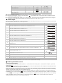
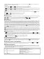
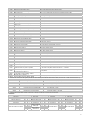
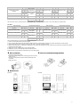
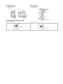
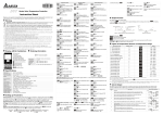
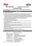
Series Valve Temperature Controller Instruction Sheet Thanks you very much for choosing Delta DTV series valve temperature controller. Please read this instruction sheet before using your DTV to ensure proper operation. Keep this instruction handy for quick reference. Warning DANGER! CAUTION! ELECTRIC SHOCK! When the power is on, DO NOT touch the AC terminals in case an electric shock may occur. Make sure the power is disconnected when you check the input power. DTV is an OPEN-TYPE device. If it will cause serious injury to workers or damage on other equipments when used in a dangerous environment, please make sure it is installed in an automatic safety protection device. 1. Always use recommended solder-less terminals: Fork terminal with isolation (M3 screw, Max. width 7.2mm). Please be sure to tighten them properly and make sure the wire is connected to the correct terminal. 2. Prevent dust or metallic debris from falling into the device and cause malfunction. DO NOT modify or uninstall DTV series without being permitted. DO NOT use empty terminals. 3. Keep away from high-voltage and high-frequency environment during installation in case of interference. Prevent using DTV in premises which contain: (a) dust or corrosive gas; (b) high humidity and high radiation; (c) shock and vibration 4. The power has to be switched off when wiring or changing temperature sensor. 5. Make sure to use compensation wire which matches the thermocouple when extending or connecting the thermocouple wire. 6. Use wires with resistance when extending or connecting the platinum resistance sensor. 7. Keep the wire as short as possible when wiring a sensor to the temperature controller. Separate the power cable and load wire in order to prevent interference and induced noise. 8. DTV is an open-type device. Make sure to install it in an enclosure which prevents dust and humidity in case of an electric shock. 9. Make sure the power cables and signal device are installed correctly before switching on the power; otherwise serious damage may occur. 10. DO NOT touch the terminals or repair the device when the power is on; otherwise an electric shock may occur. 11. Please wait for one minute after the power is switched off to allow the capacitor to discharge. DO NOT touch the internal wiring within this period. 12. DO use dry cloth and DONOT use acid or alkaline liquid to clean the device. Display, LED & Pushbuttons PV: Present value SV: Set value %: Output percentage AT: Auto-tuning indicator A/M: Manual control indicator OUT1/OUT2: Output indicator ALM1/ALM2: Alarm output indicator Manual/auto mode switch key Selection/setup key Ordering information DTV 1 Series name 1 2 3 4 Panel size (W × H) 5 2 3 4 5 DTV: Delta V series valve temperature controller 4896: 1/8 DIN W48 × H96 mm 9696: 1/4 DIN W96 × H96 mm R: Valve, relay output SPST (250VAC, 5A) Switching page key Left-shifting the digit Specifications Power input Input power range Power consumption Display Input temperature sensor Control method Control output type Display scale Sampling cycle Vibration resistance Shock resistance Ambient temperature Storage temperature Operation altitude Ambient humidity AC100 ~ 240V, 50/60Hz 85% ~ 110%, rated voltage Less than 5VA 2-line, 7-segment LED, 4bits and 2 bits of valve openness display PV in red, SV and valve openness in green. Thermocouple: K, J, T, E, N, R, S, B, L, U, TXK Platinum resistance: Pt100, JPt100 Analog input: 0 ~ 5V, 0 ~ 10V, 0 ~ 20mA, 4 ~ 20mA, 0 ~ 50mA PID, PID programmable control, manual, On/Off Relay output: SPST, Max. load 250V, 5A resistive load 1 digit after the decimal point, or no decimal point Analog input: 0.15 sec; thermocouple/platinum resistance: 0.4 sec 10 ~ 55Hz 10m/s2 3 axes 10 min. Max. 300m/s2 3 axes 6 directions, 3 times each 0°C ~ +50°C -20°C ~ +65°C Less than 2,000m 35% ~ 80% RH (non-condensing) 1 Setting up Parameters Switching Modes: DTV is in the operation mode when the power is switched on, displaying PV and SV. Press initial setting mode. Press for less than 3 seconds in the operation mode to enter the regulation mode. Press mode to return to the operation mode. Selecting parameters: In the operation, regulation or initial setting mode, press to select parameters for setup. to modify the settings. Press Setting up number parameters: Find the parameters to be set up or modified. Use be modified and the digit will flash. Press to complete and save the setting. Setting up non-number parameters: Find the parameter to be set up or modified and use to complete and save the setting. Press Regulation Mode Press for less than 3 secs Operation Mode Press Use for more than 3 secs PD control offset Press Heating hysteresis setting (Set up when in On/Off control) Press Cooling hysteresis setting (Set up when in On/Off control) Press Set up input type Press Press Start setting up patterns (Set up when in PID programmable control mode) Press Upper limit for the temperature range Set up the position of decimal point (Not for thermocouple B, R, S type) Press Lower limit for the temperature range Press Press Press Select control mode (Enter step editing when PID programmable control is selected. See the next table) Press Press Press Press Press Set up alarm mode 1 Press Set up alarm mode 2 Press Key-locked mode Set up system alarm Press Enable/disable communication write-in Press Upper limit adjusting with feedback Output percentage of valve feedback output (Displayed when there is valve feedback) (Displayed when in valve feedback mode) Press Press Select ASCII/RTU communication format Lower limit adjusting with feedback D/A value of valve feedback output (Displayed when there is valve feedback) (Displayed when in valve feedback mode) Press Press Back to top Press Set up communication address Press Press Press Set up baud rate Adjusting PV offset Press Upper limit for control output Press Set up data length Lower limit for control output Press Press Displaying and adjusting output percentage (Displayed when in PID mode and manual RUN) Press Valve DeadBand Setting Select heating or cooling open Press Lower limit for alarm 2 (Adjustable when ALA2 is enabled) Upper limit for alarm 1 (Adjustable when ALA1 is enabled) Time from valve fully closed to fully Press Set up temperature unit (Not displayed when in analog input mode) Press Upper limit for alarm 2 Switch for valve feedback setting (Adjustable when ALA2 is enabled) Press Press Control loop RUN/STOP Heating/cooling control cycle Lower limit for alarm 1 (Adjustable when ALA1 is enabled) Press Auto adjusting feedback value (Displayed when in valve feedback mode and STOP) Press Initial Setting Mode Initial Setting Mode to set up SV Select the PID group (0 ~ 4) (4 groups of PID are available in PID control. n = 4: PID is auto-selected. See the next table.) Press / to modify the setting. The parameter will flash at this time. Operation Mode Auto-tuning (Set up when in PID control and RUN) Press to move to the desired digit to Press Press Regulation Mode for more than 3 seconds to enter the once in the regulation or initial setting Back to top Set up stop bit Press Back to top Select the PID group: The user can select one of the 4 groups. When n = 4, the program will automatically select the PID group that is the closest to the SV. 2 Regulation Mode Operation Mode Select the PID group (n = 0~4) Set up the temperature SV for PID group 3 Press PID group 0 ~ 3 Press Initial Setting Mode Set up the temperature SV for PID group 0 Press Set up the proportion band for PID group 0 Set up the proportion band for PID group 3 Press Press Set up the Ti value for PID group 0 Set up the Ti value for PID group 3 Press Press Set up the Td value for PID group 0 Set up the Td value for PID group 3 Press Press Set up the integration offset for PID group 0, Set up the integration offset for PID group 3, AT auto-setting AT auto-setting PD control offset Pres Editing patterns and steps: In parameter , select Regulation Mode for editing. Take pattern 0 for example: Operation Mode Select the pattern No. to be edited Select OFF Press Leave pattern and step editing Initial Setting Mode Select the actual number of steps in the Edit the temperature in step 0 Select No. PD control offset Press program Press Edit the time for step 0 (unit: hour/minute) Continue the setup in Press Set up the number of additional cycles (0 ~ 99) Press Press Press Set up the link pattern. OFF = end of program Set up from step 0 ~ step 7 in order Edit the temperature in step 7 Press Press Return to “select the pattern No. to be edited” Edit the time for step 7 (unit: hour/minute) Following the actual number of steps Output Control DTV offers heating and cooling outputs. In parameter , you can select either to operate heating control or cooling control. Select Heating hysteresis Cooling hysteresis for heating output and for cooling output. Output ON Heating Cooling PV OFF Heating Cooling Set point PV Set point Figure 1: Output operation when in On/Off control Figure 2: PID control Key-locked Function : Lock all the keys on the panel. : Only SV can be modified. : Only SV and auto/manual mode can be modified (The control mode has to be PID control). Press and at the same time to unlock the keys. Types of Temperature Sensors & Temperature Range Input Sensor Type Register Value Display Range 0 ~ 50mV analog input 17 -999 ~ 9,999 4 ~ 20mA analog input 16 -999 ~ 9,999 0 ~ 20mA analog input 15 -999 ~ 9,999 0V ~ 10V analog input 14 -999 ~ 9,999 0V ~ 5V analog input 13 -999 ~ 9,999 Platinum resistance (Pt100) 12 -200 ~ 600°C Platinum resistance (JPt100) 11 -20 ~ 400°C Thermocouple TXK type 10 -200 ~ 800°C Thermocouple U type 9 -200 ~ 500°C Thermocouple L type 8 -200 ~ 850°C Thermocouple B type 7 100 ~ 1,800°C Thermocouple S type 6 0 ~ 1,700°C 3 Thermocouple R type Input Sensor Type Register Value 5 Display Range 0 ~ 1,700°C Thermocouple N type 4 -200 ~ 1,300°C Thermocouple E type 3 0 ~ 600°C Thermocouple T type 2 -200 ~ 400°C Thermocouple J type 1 -100 ~ 1,200°C Thermocouple K type 0 -200 ~ 1,300°C Note 1: The current input is built-in with a 249Ω precision resistor. See “How to Set up Current Input” section. Note 2: The default setting is Pt100 input. Note 3: To display the decimal point, you have to set up the parameter (in the operation mode). The decimal point display is available for all modes except for thermocouple B, R, and S type. Note 4: The range for analog input is -999 ~ 9,999. Take 0 ~ 20mA for example, -999 refers to 0mA input and 9,999 refers to 20mA input. If we change the range into 0 ~ 2,000, 0 will thus refer to 0mA input and 2,000 refers to 20mA input (1 display scale = 0.01mA). Alarm Output DTV offers 2 groups of alarm outputs and 17 modes for each group under the initial setting mode. When the PV exceeds or falls below SV, the alarm output will be enabled. See the table below for the 17 alarm output modes. Mode 0 Alarm Type Alarm Output Operation Off No alarm 1 Alarm output is enabled when the temperature reaches upper and lower limits. Alarm will be enabled when the PV exceeds SV + AL-H or falls below SV - AL-L. 2 Alarm output will be enabled when the temperature reaches the upper limit. Alarm will be enabled when the PV exceeds SV + AL-H. 3 Alarm output is enabled when the temperature reaches the lower limit. Alarm will be enabled when the PV falls below SV – AL-L. ON OFF AL-L SV AL-H SV AL-H ON OFF ON OFF AL-L SV AL-L SV ON OFF 4 Alarm output will be enabled when the PV is between SV + AL-H and SV – AL-L. 5 Alarm output is enabled when the temperature reaches the absolute value of the upper and lower limits. Alarm will be enabled when the PV exceeds AL-H or falls below AL-L. 6 Alarm output is enabled when the temperature reaches the absolute value of the upper limit. Alarm will be enabled when the PV exceeds AL-H. 7 Alarm output is enabled when the temperature reaches the absolute value of the lower limit. Alarm will be enabled when the PV falls below AL-L. 8 Standby upper/lower limit alarm: Alarm will be enabled when the PV reaches SV and exceeds SV + AL-H or falls below SV – AL-L. AL-H ON OFF AL-L AL-H ON OFF AL-H ON OFF AL-L ON OFF AL-L SV AL-H SV AL-H ON 9 Upper limit standby alarm: Alarm will be enabled when the PV reaches SV and exceeds SV + AL-H. OFF ON 10 Lower limit standby alarm: Alarm will be enabled when the PV reaches SV and falls below SV – AL-L. OFF AL-L 11 Upper limit hysteresis alarm: Alarm will be enabled when the PV exceeds SV + AL-H. Alarm will be disabled when the PV falls below SV + AL-L. 12 Lower limit hysteresis alarm: Alarm will be enabled when the PV falls below SV – AL-H. Alarm will be disabled when the PV exceeds SV – AL-L. 14 15 Programmable STOP: Alarm will be enabled when the program is in STOP status. Programmable RAMP UP: Alarm will be enabled when the program is in RAMP UP status. 16 Programmable RAMP DOWN: Alarm will be enabled when the program is in RAMP DOWN status. 17 18 Programmable SOAK: Alarm will be enabled when the program is in SOAK status. Programmable RUN: Alarm will be enabled when the program is in RUN status. SV ON OFF AL-L AL-H ON OFF AL-H AL-L Note: AL-H and AL-L include AL1H, AL2H and AL1L, AL2L. There is no mode 13 (reserved for CT function). PID Programmable Control Functions and Parameter Setting: The PID programmable control includes 8 patterns (Pattern 0 ~ 7). Each pattern contains 8 steps (Step 0 ~ 7) and parameters: link pattern, cycle and the number of steps. Start Pattern : This parameter can be set in the operation mode. The user can set up which pattern is the start pattern for the programmable control. This function is only available when the program is in STOP status. Step: Includes the settings of the two parameters, set point X and execution time T, indicating that the set point (SV) has to rise to temperature X after the period of execution time T. If the result of the set point X is the same as that of the previous setting, the process is called Soak; otherwise, it is called Ramp. Therefore, the programmable control is also known as Ramp/Soak control. The default setting of the first step program is Soak control. The temperature will first rise to the set point X and remain at X. The total execution time is T. Link Pattern: For example, if the parameter is set as is set as 2, it refers to the execution of pattern 2 will follow the execution of pattern 0. If the link pattern , it refers to the program will end after the execution of the pattern is completed and the temperature will remain at the SV for the last step. Cycle: The additional number of cycles for a pattern. For example, if the parameter additionally, totaling the executions to 3 times including the original one. is set as 2, it refers to pattern 4 has to execute twice 4 The Number of Steps: The number of steps in each pattern (range: 0 ~ 7). For example, if the parameter execute step 0 ~ step 2 and other steps will not be executed. is set as 2, it refers to pattern 7 will The Execution: 1. When the parameter is set as 2. When the parameter is set as , the program will stop and the control output will be disabled. 3. When the parameter is set as , the program will stop and the temperature will stop at the SV before the program stops. When you select , the program will start its execution from step 0 of the start pattern. again, the program will execute again from step 0 of the start pattern. 4. When the parameter is set as , the program will stop and the temperature will stop at the SV before the program stops. When you select again, the program will resume the step before the program stops and execute by the remaining time. Display: In PID programmable control, some SVs are re-set as P-XX. P refers to the current pattern and XX refers to the current step. Press display. Select and press . SV will display the target temperature for the current step. Select and press . SV will display the remaining time of the current step. to modify the PID Control In PID control, you can select any one of the 4 groups of PID parameter (P, I, D, IOF). After auto-tuning, the PID value and the temperature SV will be stored into the selected PID parameter. ~ : PIDn, n = 0 ~ 4. 0 ~ 3 are the corresponding selected PID parameter. refers to auto-selected PID and the program will ~ corresponding to n = 0 ~ 3. automatically select a most useful PID parameter based on the current SV. SV displays will be ~ : The SV for the selected PID parameter, can be set by the user or auto-generated by auto-tuning. Valve Control Heaters and coolers can be used to control the temperature and the openness of the valve in order to control the flow of the medium. Current and voltage can control the openness of the valve; however, the most direct and economic way to control the openness of the valve is the relay. To control the valve by voltage and current, you can use the DTB series analog output controller. If you tend to use relay for the control output, you have to choose the valve function in DTV series. The two control outputs are relay output for the forward/reverse running of the motor to drive the opening and closing of the valve. Control output1 controls the opening of the valve and control output 2 controls the closing of the valve in order to adjust the position of the valve. In order to detect the position of the valve, DTV is able to receive “feedback signal” and “no feedback signal”. When there is no feedback signal and the valve is fully open, control output 1 will output continuously. If at the moment the valve is fully closed, control output 2 will output continuously. If the valve you use is with feedback output, you can connect the output of the valve to the feedback part of DTV and set to On to precisely control the openness of the valve. If there is no feedback signal or the feedback signal is incorrect, and the pre-set openness of the valve is not reached after twice as long as the time set in the , the program will automatically switch back to the no feedback state. To ensure the correctness of the valve control, please make sure parameter that you have set up the parameters below: : Time required from the valve fully closed to fully open. This parameter has to be correct when the valve is without feedback signal; otherwise, the accuracy for the temperature control will be affected. The PID control will correspond to the openness of the valve according to the setting of this parameter. : DeadBand value of the valve. The parameter is to prevent frequent movement of the valve. For example, assume the DeadBand is 4%, PID control will correspond to the openness of the valve within 4% and the valve will not move within the range unless the value is accumulated and exceeds 4%. If the Deadband value is too small and the valve is set to have feedback signals, moving back and forth of the valve will shorten the life of the valve motor. : With or without feedback signals. When a) is set as “On”, it refers to “with feedback signals” and the following parameters will be displayed. : Automatically adjusting the upper/lower limit of the valve feedback. This parameter will only be displayed when is set as . When this parameter is set as On, the relay will enable the forward and reverse running of the motor in order to calculate the time needed from the valve fully closed to fully open and the feedback signal of fully closed and open. The feedback signal is the hardware D/A value of the valve control, which is for the calculation of the valve controller. b) : Upper limit of the valve signal. Set as “On”, can be set automatically or manually. c) : Lower limit of the valve signal. Set as ”On”, can be set automatically or manually. Auto/Manual Mode Switch A/M indicator On refers to manual mode; A/M indicator Off refers to auto mode. Besides On/Off, PID, programmable and manual controls, the valve control is also able to forcibly switch to manual control (fixing the openness of the valve, unit: % from valve fully closed to fully open) when in PID control mode. You simply need to press in PID control mode to switch to manual mode and A/M indicator will be On. Press again to return to PID control and A/M indicator will be Off. Upper/Lower Limits of Valve Openness Assume we would like the maximum openness of the valve to be 80% and the minimum to be 20%, set the parameter and the valve openness of PID control, programmable control and manual control will fall within this range. as 80 and as 20, RS-485 Communication 1. Supports transmission speed 2,400bps, 4,800bps, 9,600bps, 19,200bps and 38,400bps; does not support communication format 7, N, 1/8, E, 2/8, O, 2. Communication protocol: Modbus (ASCII or RTU). Function: 03H (able to read max. 8 words in the register), 06H (able to write 1 word into the register), 01H (able to read max. 16 bits of data), 05H (able to write 1 bit into the register). 2. Address and content of the data register. Address Content 1000H Present temperature value (PV) 1001H Set point (SV) Explanation Unit: 0.1 degree, updated every 0.4 second. The read values below indicate the occurrence of errors: 8002H: temperature not acquired yet 8003H: temperature sensor not connected 8004H: wrong sensor type 8006H: unable to acquire temperature, ADC input error 8007H: unable to read/write the memory Unit: 0.1 degree 5 Address 1002H 1003H 1004H 1005H 1006H 1009H 100AH 100BH 100CH 100DH 1010H 1012H 1014H 1015H 1016H 1017H 1018H 1019H 101AH 101BH 101CH 101DH 101EH 101FH 1020H 1021H 1023H 1024H 1025H 1026H 1027H 102AH 102BH 102CH 102FH 1030H 1040H ~ 1047H 1050H ~ 1057H 1060H ~ 1067H Content Upper limit of temperature range Lower limit of temperature range Input sensor type Control method Selecting heating/cooling control Proportion band value Ti value Td value Default integration value Offset compensation value for proportional control (when Ti = 0) SV of output hysteresis Read/write of output percentage Upper limit regulation for analog linear output Lower limit regulation for analog linear output Temperature offset regulation value Analog decimal point setting Time from valve fully closed to fully open DeadBand setting of valve Upper limit for valve feedback signal Lower limit for valve feedback signal PID group setting SV for the corresponding PID setting Upper limit for control output Lower limit for control output Output mode for alarm 1 Output mode for alarm 2 System alarm setting Upper limit for alarm 1 Lower limit for alarm 1 Upper limit for alarm 2 Lower limit for alarm 2 Read/write LED status Read/write key status Panel lock status Software version No. of start pattern Explanation The content shall not be bigger than the range. The content shall not be smaller than the range. See “Types of Temperature Sensors and Temperature Range" table. 0: PID; 1: On/Off; 2: manual control; 3: PID programmable control 0: heating; 1: cooling 0.1 ~ 999.9 0 ~ 9,999 0 ~ 9,999 0 ~ 100%, unit: 0.1% 0 ~ 9,999 Unit: 0.1%, only applicable in manual control mode 1 scale = 2.8μA = 1.3mV 1 scale = 2.8μA = 1.3mV -99.9 ~ +99.9, unit: 0.1 0~3 0.1 ~ 999.9 0 ~ 100%, unit: 0.1% 0 ~ 1,024 0 ~ 1,024 0~4 In valid range. Unit: 0.1 Lower limit for control output ~ 100%, unit: 0.1% 0 ~ Upper limit for control output, unit: 0.1% See “Alarm Output” section. See “Alarm Output” section. 0: None (default); 1 ~ 2: Set alarm 1 ~ alarm 2 See “Alarm Output” section. See “Alarm Output” section. See “Alarm Output” section. See “Alarm Output” section. b0: °F; b1: °C; b2: ALM2; b3: x; b4: OUT1; b5: OUT2; b6: AT; b7: ALM1 b0: Set; b1: Select; b2: Up; b3: Down; 0 refers to push. 0: normal; 1: lock all; 11: SV adjustable; 111: SV adjustable, A/M available V1.00 refers to 0x100 0~7 Number of steps in a pattern 0 ~ 7 = N refers to the pattern will be executed from step 0 to step N. Additional number of cycles for a pattern 0 ~ 99 refers to the pattern will be executed for 1 ~ 100 times. No. of the link pattern for the current pattern 0 ~ 8. 8 refers to end of the program; 0 ~ 7 refers to the next pattern No. following the current pattern. 0 ~ 100%, unit: 0.1% SV temperature for pattern0 ~ 7 -999 ~ 9,999 SV for pattern 0 is set in 2000H ~ 2007H Execution time for pattern 0 ~ 7 2080H ~ 0 ~ 900 (Every scale = 1 minute) 20BFH Time for pattern 0 is set in 2080H ~ 2087H 3. Address and content of the bit register (read bits are stored starting from LAB and written data is FF00H, set the bit as 1. 0000H sets the bit data as 0.) 0810H Selecting communication write-in Communication write-in forbidden: 0 (default), allowed: 1 0811H Selecting temperature unit 0: °F; 1: °C/linear input (default) 0812H Position of the decimal point 0 or 1. Available for all modes except for thermocouple type B, S, R. 0813H Read/write auto-tuning (AT) 0: AT stops (default); 1: AT starts 0814H RUN/STOP of the control 0: stop; 1: run (default) 0815H Programmable control RUN/STOP 0: run (default); 1: stop 0816H Programmable control RUN/PAUSE 0: run (default); 1: pause 0817H Read/write valve feedback 0: without feedback (default); 1: with feedback 0818H Read/write AT of valve feedback 0: AT stops (default); 1: AT starts 4. Communication transmission format: command 01: read bit, 05: write bit, 03: read word, 06: write word. ASCII Mode Read Command Read Response Message Write Command Write Response Message ’:’ ’:’ ’:’ ’:’ ’:’ ’:’ ’:’ ’:’ Start word Start word Start word Start word 2000H ~ 203FH Machine address 1 Machine address 0 Command 1 Command 0 Read start address of data/bit ‘0’ ‘1’ ‘0’ ‘3’ ‘1’ ‘0’ ‘0’ ‘0’ ‘0’ ‘1’ ‘0’ ‘1’ ‘0’ ‘8’ ‘1’ ‘0’ Machine address 1 Machine address 0 Command 1 Command 0 Length of response data (byte) Data content in 1000H/081xH ‘0’ ‘1’ ‘0’ ‘3’ ‘0’ ‘4’ ‘0’ ‘1’ ‘0’ ‘1’ ‘0’ ‘1’ ‘0’ ‘2’ ‘1’ ‘7’ Machine address 1 Machine address 0 Command 1 Command 0 Write data address ‘0’ ‘1’ ‘0’ ‘6’ ‘1’ ‘0’ ‘0’ ‘1’ ‘0’ ‘1’ ‘0’ ‘5’ ‘0’ ‘8’ ‘1’ ‘0’ Machine address 1 Machine address 0 Command 1 Command 0 Write data address ‘0’ ‘1’ ‘0’ ‘6’ ‘1’ ‘0’ ‘0’ ‘1’ ‘0’ ‘1’ ‘0’ ‘5’ ‘0’ ‘8’ ‘1’ ‘0’ 6 Read Command Read Response Message Write Command Write Response Message ‘F’ ‘0’ ‘0’ ‘F’ ‘0’ ‘4’ ‘1’ ‘3’ ‘F’ ‘3’ Read length of data/bit Write data content Write data content (word/bit) ‘0’ ‘E’ ‘0’ ‘E’ ‘0’ ‘8’ ‘0’ ‘8’ Data content in 1001H LRC1 check ‘0’ LRC1 ‘F’ ‘E’ LRC1 ‘F’ LRC0 check ‘0’ LRC 0 ‘D’ ‘3’ LRC 0 ‘D’ End word 1 LRC1 check ‘0’ ‘E’ End word 1 CR CR End word 1 CR End word 0 LRC0 check ‘3’ ‘3’ End word 0 LF LF End word 0 LF End word 1 CR CR End word 0 LF LF LRC check: Sum up from “machine address” to “data content”, e.g. 01H + 03H + 10H + 00H + 00H + 02H = 16H. Obtain 2’s complement EA. ‘0’ ‘0’ ‘0’ ‘2’ ‘E’ ‘A’ CR LF ‘0’ ‘0’ ‘0’ ‘9’ ‘D’ ‘C’ CR LF Data content in 1000H/081xH ‘F’ ‘F’ ‘0’ ‘0’ ‘E’ ‘3’ CR LF RTU Mode Read Command Machine address Command Read start address of data Read length of data (bit/word) CRC low byte CRC high byte 01H 03H 10H 00H 00H 02H C0H CBH Read Response Message 01H Machine address 01H 01H 01H Command 03H 01H 08H Length of response 04H 02H data (byte) 10H 00H 01H 17H Data content 1 09H F4H 01H BBH 03H Data content 2 A9H 20H CRC low byte BBH 77H CRC high byte 15H 88H Write Command Machine address 01H Command 06H 10H Write data address 01H 03H Write data content 20H CRC low byte DDH CRC high byte E2H 01H 05H 08H 10H FFH 00H 8FH 9FH Write Response Message Machine address 01H 01H Command 06H 05H 10H 08H Write data address 01H 10H 03H FFH Write data content 20H 00H CRC low byte DDH 8FH CRC high byte E2H 9FH CRC (Cyclical Redundancy Check) is obtained by the following steps. 1. Load in a 16-bit register FFFFH as the CRC register. 2. Do an exclusive OR operation of the first byte of the data and low byte of CRC register, and place the operation result back to the CRC register. 3. Right shift the bits in the CRC register and fill the high bits with “0”. Check the removed lowest bit. 4. If the removed lowest bit is “0”, repeat step 3. Otherwise, do an exclusive OR operation of the CRC register and the value A001H and place the operation result back to the CRC register. 5. Repeat step 3 and 4 until the 8 bits (1 byte) are all right shifted. 6. Repeat step 2 and 5 and calcualte all the bits to obtain CRC check. Please be aware of the high/low byte transmission order in the CRC register. How to Mount How to Install Mounting Bracket 1. Insert DTV into the panel cutout 2. Insert the mounting bracket into the mounting groove at the top and bottom of DTV. 3. Push the mounting bracket forward until the bracket stops at the panel wall. 4. Tighten the screw. Dimensions DTV4896 DTV9696 7 Panel Cutout DTV4896/DTV9696 96*96 +0.6 120.0 min. 110.0 min. 91 0 91.5 0 120.0 min. 60.0 min. +0.6 48*96 Terminals DTV4896R/DTV9696R +0.6 44.5 0 +0.6 91 0 How to Set up Current Input For normal input (default) Current input (4 ~ 20mA, 0 ~ 20mA) JU MP ER JP1 PIN HEA DE R J UMP ER JP1 PIN HE A DE R DEFAU LT SE TTI NG 8