1
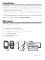
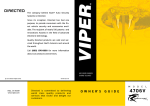
The company behind Viper® Auto Security Systems is Directed Electronics. Vista, CA 92081 www.viper.com Since its inception, Directed Electronics has had one purpose, to provide consumers with the finest vehicle security and car stereo products and accessories available. The recipient of nearly 100 patents and Innovations Awards in the field of advanced electronic technology, Directed Electronics is ISO 9001 registered. NO ONE DARES COME CLOSE Quality Directed Electronics products are sold and serviced throughout North America and around the world. Call (800) 876-0800 for more information about our products and services. © 2009 Directed Electronics, All rights reserved. Directed Electronics is an ISO 9001 registered company. G3303V 2009 11 Directed Electronics is committed to delivering world class quality products and services that excite and delight our customers. O W N E R’ S GUIDE M O D E 3303 L Congratulations Congratulations on the purchase of your state-of-the-art security system. Reading this owner’s guide prior to using your system will help maximize the use of your system and its many features. For more information please visit the below website: http://www.viper.com – For general and additional guide information. For any additional questions please contact your authorized Directed dealer or contact Directed at 1-800-753-0600. What you get Welcome to the best generation of vehicle security. Your system contains everything you need. s s s s s s Responder LC remote control 1-way companion remote control AC adapter for charging your remote control This owner’s guide Quick reference card Warranty card AUX er’s Own e u G id Warranty Card Quick Reference Card G3303V 2009-11 Important information Your Warranty Your system comes with a warranty. Please make sure you receive the warranty registration card and proof of purchase from your dealer indicating the product was installed by an authorized Directed dealer. Your product warranty must be validated within 10 days of purchase. You can validate it online at www.prodregister.com/directed or complete and return the warranty registration card. Quick Reference Card Carry this card with you to reference your system’s many features. Replacement Remote Controls If additional remote controls are desired, please see your authorized dealer or visit us at www.directedstore.com to order. Part numbers are: 7351V for Responder LC 2-way remote control and 7153V for the 1-way companion remote control. Contents Getting Started.................................................................................................... 4 Charging the Remote Control ................................................................ 4 Keys to using this Manual ..................................................................... 5 Responder LC 2-Way........................................................................................... 6 Status Screen Icons .............................................................................................. 8 Using your System ............................................................................................. 11 Commands and Confirmations ............................................................ 11 Performing Commands ....................................................................... 11 Responder LC Command table ............................................................ 12 Basic Commands (Direct Access) ........................................................................ 13 Arm ................................................................................................. 13 Disarm ............................................................................................. 13 AUX/Trunk........................................................................................ 14 Remote Start /AUX 1/ AUX 4 ............................................................. 14 Advanced Commands: (Level 1) ......................................................................... 15 Silent Arm ......................................................................................... 15 AUX 1 .............................................................................................. 15 Advanced Commands: (Level 2) ......................................................................... 16 Sensor Bypass ................................................................................... 16 Remote Valet .................................................................................... 16 AUX 2 .............................................................................................. 16 Advanced Commands: (Level 3) ......................................................................... 17 Sensor Silent Arm* ............................................................................ 17 AUX 3 .............................................................................................. 17 Alarm Report* ................................................................................... 18 Advanced Commands: (Level 4) ......................................................................... 19 Full Silent Arm* ................................................................................. 19 AUX 4 .............................................................................................. 19 Responder LC Configuration............................................................................... 20 Navigating Menus and Options .......................................................... 20 Button Operation ............................................................................... 20 Access Menu Items ............................................................................ 20 Main Menu ....................................................................................................... 21 Setup Remote Menu: .......................................................................... 21 Remote Start Info ............................................................................... 22 Runtime Alert..................................................................................... 22 Car 2 ............................................................................................... 23 BackLight .......................................................................................... 23 Temp Unit ......................................................................................... 23 Button Beep....................................................................................... 23 System Type ...................................................................................... 23 Clock Set .......................................................................................... 24 Review ............................................................................................. 24 Exit .................................................................................................. 24 Sensor Adjust: ................................................................................... 24 Pair a Responder LC remote control: .................................................... 24 Demo Mode: ..................................................................................... 25 Power Off: ........................................................................................ 26 Exit: ................................................................................................. 26 Alarm Features ................................................................................................. 27 Normal Arm Protection ....................................................................... 27 Sensor Silent Arm Protection................................................................ 27 Full Silent Arm Protection .................................................................... 28 Sensor Warn-away Messages ............................................................. 28 Full Trigger Messages ......................................................................... 28 Emergency Override .......................................................................... 28 Trigger Zone Fault Report.................................................................... 29 Alarm Report when Disarming ............................................................. 29 Alarm Report when Requested ............................................................. 30 Nuisance Prevention (NPC) ................................................................. 30 Remote and System Operations .......................................................................... 31 Passive Arming* ................................................................................ 31 Auto Re-arming* ................................................................................ 31 Valet Mode ....................................................................................... 32 Power Save....................................................................................... 32 Rapid Resume ................................................................................... 32 Automatic Remote Updates ................................................................. 32 Out of Range .................................................................................... 33 No Remote Output ............................................................................. 33 Car Select ......................................................................................... 33 Vehicle Recovery System (VRS) ............................................................ 34 1-way Companion Remote Control ..................................................................... 35 Accessing Commands ........................................................................ 36 Button Auto Lock ................................................................................ 36 Car Select ......................................................................................... 36 Programming .................................................................................... 37 Battery Information (1-way) ................................................................. 38 Low Battery Alerts .............................................................................. 38 Battery Replacement........................................................................... 38 System Expansion Options ................................................................................. 39 Battery Information (Responder LC) ..................................................................... 41 Low Battery ....................................................................................... 41 Battery Life ........................................................................................ 42 Battery Disposal ................................................................................ 43 Glossary of Terms.............................................................................................. 44 Government Regulations .................................................................................... 46 Additional information....................................................................................... 47 Interference ....................................................................................... 47 Upgrades and Batteries ...................................................................... 47 Water/Heat Resistance ...................................................................... 47 Limited lifetime consumer warranty ..................................................................... 48 Getting Started Your remote control is powered by an internal rechargeable battery that can only be serviced by an authorized Directed dealer. Due to transit and storage time prior to your purchase, the battery charge may have depleted. To ensure proper operation, check the battery level and connect the battery charger if not fully charged. See Battery Information and Status Screen Icons sections for more information about the battery. Charging the Remote Control 1. 2. 3. Plug the AC adapter into a 110V AC outlet. Insert the mini-USB connector into the mini-USB port located on the side of the remote control (see diagram under Responder LC 2-way). The text field will display CHARGE to indicate the remote control is charging (The remote remains operational while charging and can command the system). Once fully charged the text field will display FULL . The remote control is then ready for use. Disconnect the miniUSB end from the remote control first and then the AC adapter from the AC outlet. Note 4 The remote control remains operational while charging and can command the system. If the battery is excessively depleted when the charger is connected, functionality may be delayed while it charges to the minimum voltage required to operate the display, after which normal charging resumes. © 2009 Directed Electronics. All rights reserved. Keys to using this Manual Specific actions (in bold type) and style conventions are used consistently throughout this manual, they are as follows: s s s s s Press: implies pushing in and releasing a button. Hold: is used after “press” actions when a button needs to be held in position for an extended period of time, typically several seconds. ARMED this style denotes the text which appears in the text field portion of the display during operations described in the manual. If the text string is too long for the text field, it then plays and loops sequentially word by word. Italicized words denote section/sub headings in this guide and can be located through the table of contents. An asterisk (*) when used after a word or phrase denotes that additional details can be found in related sections usually noted at the bottom of the page or end of the section. © 2009 Directed Electronics. All rights reserved. 5 Responder LC 2-Way Internal Antenna Display Command Buttons Function Button Mini-USB Port Feature Description Internal Antenna Used for transmitting and receiving information Display Status screen - the upper portion of the display contains status icons for the system, siren, alarm zones, and remote control Text field - the lower portion of display shows the clock, command confirmations, page messages and programming menus 6 Command Buttons (4) Used to perform arming, disarming and auxiliary channel commands Function Button Used to access function levels for commands, configuration menus for programming, and car selection Mini-USB Port The battery charger plugs into this port © 2009 Directed Electronics. All rights reserved. Control Center Control Center Button Control Center LED The control center, typically located on the upper part of the front windshield sends and receives commands or messages to and from your system. It consists of: s s s The In-vehicle system antenna, for 2 way communication. The control center LED, as a visual indicator of the system’s status. The control center button, for placing the system into valet mode* and to perform the emergency override** operation. * See Remote and System Operations section for details. ** See Alarm Features for details. © 2009 Directed Electronics. All rights reserved. 7 Status Screen Icons Status Screen Icons ALL 1 Text Field The table below describes all the status screen icons. Icon Description System Status Armed: The system is armed, the alarm is enabled Locked: The system is locked in valet, the alarm is disabled Disarmed: The system is disarmed, the alarm is disabled Siren Status Unlocked: The system is unlocked in valet, the alarm is disabled Siren is disabled for sensor triggers; remote is paged for all triggers (sensor silent arm) + ALL Siren is disabled for all triggers; remote is paged for all triggers (full silent arm) Zone Status On during warn-away and full trigger message output 8 On during trunk zone full trigger output and aux/trunk channel activation On during fault report to indicate the trunk is open and bypassed when arming © 2009 Directed Electronics. All rights reserved. Icon Description On during a sensor zone full trigger output Zone Status On during fault report to indicate a sensor is active and bypassed when arming On during the door zone full trigger output On during fault report to indicate a door is open and bypassed when arming On during a hood zone full trigger output On during fault report to indicate the hood is open and bypassed when arming On when remote is set to command the system programmed as car 1* On when remote is set to command the system programmed as car 2* Bars indicate battery level is full, ¾,½,¼ or empty On while the remote control is transmitting a command Remote Control Status On while the remote control is receiving a message On with out of range fault tone to indicate the remote failed to receive a command confirmation Pager on: The remote will wake up to listen for messages Pager off: The remote will not wake up to listen for messages The remote will vibrate when messages are received The remote will emit beeps and tones when messages are received © 2009 Directed Electronics. All rights reserved. 9 Icon Description Text field Displays the clock, message text and feature menus On after the garage open** message has been received On after the garage closed** message has been received Remote start is active, the engine is running (with optional remote start module only) * This icon not present until the car 2 is turned on in the Setup Remote configuration menu. ** This icon not present until the remote is paired with an optional garage door opener. 10 © 2009 Directed Electronics. All rights reserved. Using your System Commands and Confirmations Commands, basic or advanced, are used to activate system features and are performed by pressing one of the command buttons. Basic commands control the most often used security features while advanced commands control more specialized features and request reports. Confirmations for basic or advanced commands are indicated first by siren chirps and parking light flashes, and then by text, icons and beeps or tones on the remote control. A description of each feature confirmation is found in the Basic Commands and Advanced Commands sections. Performing Commands Perform basic commands by pressing one of the command buttons while in the direct access level. Direct access is available while the text field displays the clock. Perform advanced commands by first accessing one of the function Levels and then pressing one of the command buttons while within a level. Function Levels are available when the text field displays LEVEL 1,2,3 or 4. Advanced Command example: Silent Arm 1. Press the button once to access function level 1, the text field will display LEVEL 1 . 2. Press the button while LEVEL 1 text is still on to perform the silent arm command. 3. The Responder LC remote will display SILENT ARMED in the text field and update the status screen icons. © 2009 Directed Electronics. All rights reserved. 11 Responder LC Command table Level Direct Access Button x1 LEVEL 1 Arm/Lock Silent Arm x3 LEVEL 3 x4 LEVEL 4 Sensor Sensor Silent Full Silent Bypass Arm Arm Silent Disarm Remote Valet Car Finder AUX 1 AUX 2 AUX 3 (Panic) Disarm/Unlock x2 LEVEL 2 Remote Start*/ Aux 1/4** AUX Aux/Trunk Advance Level Alarm Change Car Report AUX 4 (3s), Enter programming (8s) * Available only with optional remote start module installation ** This button can command either aux 1 or aux 4 if turned on by an authorized Directed dealer. 12 © 2009 Directed Electronics. All rights reserved. Basic Commands (Direct Access) Arm Press and release 6:30 The alarm arms, doors lock (if connected), and the siren chirps and parking lights flash once. The ARMED text and beeps play to confirm and the system status icons update. If valet mode* is on, the doors lock and the VALET text and tone play. Exit valet mode to arm the alarm normally. If a trigger zone fault is detected the siren chirps once again and the trigger zone fault report** plays. To Arm and Panic Press and hold The alarm arms (or locks in valet) and, after 2 seconds, sounds the siren and flashes the parking lights. The PANIC text and siren tones play to confirm. Press the or button to stop the output. Disarm Press and release The alarm disarms, doors unlock (if connected), and the siren chirps and parking lights flash twice. The DISARM text and beeps play to confirm and the system status icons update. If valet mode* is on, the doors unlock and the VALET text and tone play. More than 2 siren chirps and remote beeps indicate a trigger has occurred. The DISARM text is replaced by the alarm report.** © 2009 Directed Electronics. All rights reserved. 13 AUX/Trunk Press and hold AUX The trunk opens (if connected) when this button is pressed for 2 seconds. The TRUNK text and tones play to confirm. Remote Start /AUX 1/ AUX 4 Press and release Remote Start*** Activates (or if on, deactivates) the remote starter. The engine and parking lights turn on or off accordingly. The REMOTE START ON text and tones play, or the REMOTE START OFF text and tones play to confirm. The icon is displayed in the status screen while the engine is running. AUX 1/AUX 4**** Activates (or if on, deactivates) the aux 1 or aux 4 output. The programmed text and on tones or off tones play to confirm, (See System Expansion Options). * ** *** **** 14 See Remote and System Operations for details. See Alarm Features for details. Available only with optional Remote Start module installation. This feature must be turned on by an authorized Directed dealer. © 2009 Directed Electronics. All rights reserved. Advanced Commands: (Level 1) Press and release the button 1 time. level 1 Silent Arm Press and release The alarm arms, doors lock (if connected), and the parking lights flash once. The SILENT ARMED text plays to confirm and the system status icons update. Valet mode* or trigger zone fault report** messages may be received. Silent Disarm Press and release The alarm disarms, doors unlock (if connected), and the parking lights flash twice. The SILENT DISARM text plays to confirm and the system status icons update. The alarm report** may replace the silent disarm text. AUX 1 Press and release AUX Activates (or if on, deactivates) the aux 1 output. The programmed text and on tones or off tones play to confirm, (See System Expansion Options). * See Remote and System Operations section for details. ** See Alarm Features for details. © 2009 Directed Electronics. All rights reserved. 15 Advanced Commands: (Level 2) Press and release the Sensor Bypass button 2 times. level 2 Press and release Performing the sensor bypass command will incrementally bypass sensor operations and be confirmed as follows: s Warn-away bypass: The parking lights flash 2 times, BYPASS WARN 1 beep and 1 fault tone play to confirm. Sensors will be activated for full trigger levels of impact only. s Warn-away full trigger bypass: The parking lights flash 3 times, BYPASS FULL , 1 beep and 2 fault tones play to confirm. Sensors will not be activated for any level of impact. s Sensor Bypass off: The parking lights flash 1 time BYPASS OFF and 1 beep play to confirm. Sensors are fully operational. If disarmed, NOT AVAILABLE and a fault tone will play. Remote Valet Press and release Enters (or if on, exits) valet mode. The VALET text and beeps (1 for on, 2 for off) play to confirm and the system status icons update. See Valet Mode for more details AUX 2 Press and release AUX Activates (or if on, deactivates) the aux 2 output. The programmed text and on tones or off tones play to confirm, (See System Expansion Options). 16 © 2009 Directed Electronics. All rights reserved. Advanced Commands: (Level 3) Press and release the button 3 times. Sensor Silent Arm* level 3 Press and release The alarm arms, doors lock, the siren chirps and parking lights flash 3 times. The SENSOR SILENT ARM text and beeps play to confirm and the system and siren status icons update. Car finder Press and release The siren emits one long chirp and the parking lights flash for 10 CAR FINDER seconds. The text and beeps play to confirm. The parking light flashes stop if armed or disarmed while car finder is in progress. AUX 3 Press and release AUX Activates (or if on, deactivates) the aux 3 output. The programmed text and on tones or off tones play to confirm, (See System Expansion Options). © 2009 Directed Electronics. All rights reserved. 17 Alarm Report* Press and hold the button Requests a report of the most recent triggers and temporarily displays it in the text field. The report clears when the ignition is turned on. * See Alarm Features for more details. 18 © 2009 Directed Electronics. All rights reserved. Advanced Commands: (Level 4) Press and release the button 4 times. Full Silent Arm* level 4 Press and release The alarm arms, doors lock, and the siren chirps and parking lights flash 4 times. The FULL SILENT ARM text and beeps play to confirm and the system and siren icons update. AUX 4 Press and release AUX Activates (or if on, deactivates) the aux 4 output. The programmed text and on tones or off tones play to confirm (See System Expansion Options). * See Alarm Features for more details. © 2009 Directed Electronics. All rights reserved. 19 Responder LC Configuration Operations of the Responder LC and how it communicates messages are set in the configuration main menu. Navigating Menus and Options Navigating menus and features, changing options, and exiting are performed using the remote control buttons. The following instructions discuss how to access and configure the settings. Button Operation s s s To access menus, set options, and to perform actions that are displayed in the text field, use the button. To scroll the menu lists in the text field use the or buttons. To exit configuration: use the or buttons. AUX Access Menu Items 1. 2. 3. Press and hold the button for 8 seconds, the remote will beep once, MAIN MENU is displayed. (If car 2 is on, ignore the car select text and beep after 3 seconds). Release the button to display the main menu item list, SETUP REMOTE is displayed. The main menu has been accessed and configuring can begin. Use the following process to view the main menu features, options and settings in the text field. The following actions are commonly used throughout the configuration operation. s Press the or buttons to change the feature or option that is displayed in the text field. s Press the button to choose the feature in the text field and view its options. Press it when the desired feature or option is in the text field to set it as the new setting. AUX 20 © 2009 Directed Electronics. All rights reserved. Main Menu The following main menu list of features is available for configuration of the remote control. Setup Remote Menu: Keypad Lock Options: OFF , AUTO When OFF , the buttons do not lock and always perform a command when pressed. When set to AUTO , the buttons lock after a 20 second lapse between buttons presses to prevent unintentional operations. If a button is pressed when locked a fault tone plays as an alert followed by unlock instructions in the text field. To unlock the buttons, press the button followed by the button. The unlock tones play and READY is displayed in the text field, a command can now be performed. Auto unlocking After turning the ignition off, a message to the remote will unlock the buttons until a command is performed. If auto unlocking is not desired this feature can be turned off by an authorized Directed dealer. Page Mode Options: POWER SAVE , OFF , ON Paging is how the Responder LC remote control monitors your system’s messages. POWER SAVE extends battery life by turning paging off after 72 hours if the remote control is not used during © 2009 Directed Electronics. All rights reserved. 21 this period. Just press any button to resume system monitoring. When set to ON it wakes up every few seconds to listen for pages from the system. When set to OFF it does not wake up to receive alarm trigger pages. Note: When OFF , responses are still received when a command is performed but alarm trigger pages will not be received. Page Alert Options: TONE VIBE , TONE , VIBE , SCREEN ONLY There are several ways for the Responder LC to alert you when it has received a message from the system. TONE VIBE will alert by both emitting tones and vibrating the remote. Select TONE to be alerted by tones that are unique for each message. Select VIBE and the Responder LC will silently alert you with a gentle vibration, or select SCREEN ONLY when you don’t want to be interrupted. Remote Start Info Options: RUNTIME , TEMP , CLOCK These options are only available when paired to a Directed Electronics remote start or remote start and security system. Runtime Alert Options: ON , OFF These options are only available when paired to a Directed Electronics remote start or remote start and security system. 22 © 2009 Directed Electronics. All rights reserved. Car 2 Options: OFF , ON , HOME This remote can control two systems independently. When set to OFF , the car 2 select option is not available. When set to ON the remote can be set to control 2 systems. The HOME option is for pairing to a home security system. BackLight Options: OFF , ON The status screen backlighting can be illuminate during remote operations. OFF , or when ON will Temp Unit Options: F ,C These options are only available when paired to a Directed Electronics remote start or remote start and security system. Button Beep Options: ON , OFF When set to ON , the remote will emit a beep as confirmation of a button press. When set to OFF , beeps are not emitted for button presses. System Type Options: SEC , RKE © 2009 Directed Electronics. All rights reserved. 23 Selects the type of system, namely; security or remote keyless entry to which the remote has been paired, and adjusts the text and main menu accordingly. This has been pre-set by the factory for your system. Clock Set Options: HOUR , MIN The clock is formatted for 12 hour mode with AM or PM indicated. Once the desired time is set return to one of the text displays ( HOUR / MIN / BACK ) before exiting to save the new time. Exiting clock set while time is still in the display will revert to the previous setting. Review Displays firmware version Exit Exits and returns to the main menu Sensor Adjust: If you feel your security system shock sensor is too sensitive or not sensitive enough, it is highly recommended that you contact your authorized Directed dealer/professional and have the sensor adjusted for optimized security detection performance. Pair a Responder LC remote control: Pairing is a process where the Responder LC and the system in the vehicle learn each others encrypted identification, securing their communication from intruders. Please note that your remote controls come pre-programmed from the factory. 24 © 2009 Directed Electronics. All rights reserved. Prepare the system 1. Open a door. 2. Turn the ignition on. 3. Press and release then press and hold the control center button. The control center LED flashes and the siren chirps one time to confirm the system is prepared. 4. Release the control center button and proceed below. Note: Begin pairing within 60 seconds or the system will exit (indicated by a long siren chirp) and will need to be prepared again. Prepare the remote control Select the desired Car 1 (Default) or Car 2 operation before proceeding. 1. 2. 3. 4. 5. Press and hold the button of the remote control until a long beep is emitted and MAIN MENU is displayed (If programmed to operate two systems, confirm the correct car 1 or car 2 text and beeps at 3 seconds). Release the button to view the main menu. REMOTE SETUP is displayed. PAIR REMOTE Press and release the button two times. is displayed. Press and hold the button until PAIR is displayed, and then release it. Press and hold the button until the siren emits a long chirp. SUCCESS is displayed with a sequence of chimes. Note: If FAILED is displayed, make sure the system is still prepared and repeat step 5 until successful. © 2009 Directed Electronics. All rights reserved. 25 Demo Mode: Demo mode plays a pre-selected group of animations as a demonstration tool to show friends or family. Running demo mode shortens the battery life over time if used excessively SINGLE SILENT : The remote will display a selection of icons on s the status screen without beeps and tones then stop s SINGLE SOUND : The remote will display a selection of icons on the status screen with beeps and tones then stop LOOP SILENT : The remote will display a selection of icons on s the status screen without beeps and tones in an endless loop until the battery charger is disconnected. LOOP SOUND : The remote will display a selection of icons on s the status screen with beeps and tones in an endless loop until the battery charger is disconnected. Note: Loop silent and loop sound are not available and will not appear in the demo mode menu unless the battery charger is connected. Power Off: When an extended period of non-operation is anticipated, turning the power off will preserve the battery charge. Press the button while POWER OFF is displayed. The status screen icons clear as the power off tones play, the remote is turned off. To turn the remote on, Press and hold the button for 3 seconds, the status screen icons refresh as the power on tones play. The remote also turns itself on and begins charging when the battery charger is connected. Exit: To return to normal operation, press the played. 26 button while EXIT is dis- © 2009 Directed Electronics. All rights reserved. Alarm Features Normal Arm Protection Control center LED: The control center LED flashes as a visual indicator that your vehicle’s security system is active. Starter Kill: The failsafe starter kill relay prevents the engine from starting Note May require additional parts and installation Sensor triggers: The onboard shock sensor can distinguish minor impacts from major impacts to the vehicle exterior. Minor impacts causes the system to emit a warn-away output by chirping the siren and flashing the parking lights for 3 seconds. Major impacts caused for example by a forcible entry attempt, results in a full trigger output. The siren sounds and the parking lights flash for 30 seconds or longer. Both warn-away and full triggers send a message to the remote control. Point of entry triggers: Opening the hood or trunk causes a full trigger output, while opening a door or turning on the Ignition causes the siren to chirp 3 seconds before beginning the full trigger output. This 3 second delay allows time to disarm and silence the siren in case of accidental trigger. The full trigger message is still sent to the remote. Sensor Silent Arm Protection Sensor warn-away and sensor full trigger activations only send messages to the remote, while the parking light flash and siren outputs are defeated. Point of entry triggers will activate the parking light flash, siren, and send messages normally. © 2009 Directed Electronics. All rights reserved. 27 Full Silent Arm Protection Sensor warn-away, sensor full trigger and point of entry activations will only send messages to the remote, with parking light flash and siren outputs defeated. Sensor Warn-away Messages When the remote receives a sensor warn-away message it emits 10 beeps (if on) and displays a sensor zone specific SENSOR WARN text for 30 seconds. Warn-away messages cannot be reviewed or displayed in reports. Full Trigger Messages A full trigger message generates a full trigger output of siren tones and zone specific TRIGGER text followed by an alert that consists of 1 long beep per minute for 10 minutes. To stop the output and alert, press a command button to perform a command, or Press the button. Emergency Override The following procedure disarms the system when a programmed remote is not available. Number of presses__________ 1. Turn the ignition on. 2. Press the control center button the correct number of times (the default is 1 press). 3. After a few seconds the siren output ceases and the system is disarmed. Note 28 As a precaution, if programmed for passive arming or auto re-arming the system should be placed into valet mode until a remote is available . © 2009 Directed Electronics. All rights reserved. Trigger Zone Fault Report When armed by remote command the system runs a status check of the alarm trigger zones. Faulty zones (usually caused by dome light delay or open trunk) are bypassed and reported via the control center LED and remote, while all other trigger zones remain active and are monitored to protect the vehicle. Should a faulty zone self correct (dome light turns off) it becomes active and is then monitored normally. The siren chirps once again a few seconds following the arming chirps as an audible alert, the control center LED flashes in groups to indicate the zone number. The remote will emit a single fault tone and play zone specific text that identifies the faulty zones. Alarm Report when Disarming The most recent alarm triggers (if any) are reported when the alarm is disarmed via the remote control, siren chirps, parking light and control center LED flashes. The siren chirps 4 times (or 5 times if NPC on*), the parking lights flash 3 times, and the control center LED flashes in groups to indicate the last two zones that were triggered (see Table of Zones). The DISARM text is replaced by ALARM REPORT and text identifying the triggers. The report output will repeat for each disarm operation until the vehicle is driven. * See Nuisance Prevention (NPC) for more details. © 2009 Directed Electronics. All rights reserved. 29 Table of Zones Zone # (led flashes) Zone Name 1 Trunk 2 Shock Sensor 3 Door 4 Sensor 2 5 Ignition 6 Hood 7 Sensor 3 Alarm Report when Requested The alarm report displays the two most recent alarm triggers depending on the system state when requested. When disarmed, the report will display text to identify the two most recent triggers since the vehicle was last driven. When armed, the report will display text to identify the two most recent triggers since the system was armed. Note The Alarm Report clears when ignition is turned on. Nuisance Prevention (NPC) NPC monitors all alarm zones and, if any are triggered excessively, bypasses them until corrected. If a point of entry (trunk, hood, door) is left open following a forced entry, it is bypassed. It becomes active again only after being closed. Bypassed sensors automatically reset after one hour and after the vehicle is driven. Disarming then re-arming the alarm does not reset bypassed sensors. 30 © 2009 Directed Electronics. All rights reserved. Remote and System Operations Passive Arming* Park and exit the vehicle, after the doors are closed the passive arming countdown begins. The control center LED flashes quickly and upon reaching 20 seconds the siren then chirps once. At 30 seconds the system arms itself. Anytime before the system arms you can re-enter the vehicle or open the trunk to load or unload items and, after closing passive arming resumes. To stay secure in the case of accidentally disarming the system, if a door is not opened within 30 seconds the system re-arms itself and locks the doors. Auto Re-arming* Auto re-arm ensures the vehicle stays protected if it is not entered after disarming by remote control. After disarming by remote, the alarm automatically re-arms itself (and locks the doors if programmed on) in 30 seconds. Open any point of entry to stop the re-arm until the next disarm by remote. Onetime Bypass* Turn the ignition on for one to three seconds and then off. The siren chirps once to confirm one-time bypass is enabled. One-time bypass can be used to temporarily bypass the passive arming operation for one cycle. It also bypasses the comfort closure and auxiliary channel outputs programmed to activate when arming. After the next disarm all operations return to normal. * These features must be turned on by an authorized Directed dealer. © 2009 Directed Electronics. All rights reserved. 31 Valet Mode Valet mode can be entered and exited by performing the remote valet command or manually using the vehicle key and the control center button. When entered, the alarm functions are defeated while the convenience features still operate normally. Arm and disarm commands lock and unlock the doors while the VALET text and beeps play to confirm. Use 1. 2. 3. the following steps to manually enter and exit valet mode: Turn the ignition switch on and then off Immediately press and release the control center button once The control center LED turns on when entering and off when exiting. Power Save To reduce power consumption the control center LED modifies its output if the vehicle is parked for an extended period. If armed the flashing is reduced after 24 hours. When valet mode is on the control center LED will turn off after 1 hour and will reset each time the ignition is turned off. Rapid Resume If power is ever disconnected by a mechanic or thief, the system will resume the state it was in at the time of disconnection, when power is reconnected. Automatic Remote Updates The system sends a silent message to all remote controls after any major action has occurred. When the remote receives this message it updates the status screen icons. This way all users are able to quickly review the system status just by accessing the status screen. 32 © 2009 Directed Electronics. All rights reserved. Out of Range Each time a command is performed the remote will expect a command confirmation from the system. If a command confirmation is not received the out-of-range icon ( ) and a fault tone will play as an alert. No Remote Output Occasionally when a command is performed the remote may not generate a command confirmation output or out of range output. This indicates that the system received the command but it was an incomplete command (e.g. aux button pressed too short to activate the trunk release) or it was an illegal message (e.g. the command was corrupted due to local RF interference). These are temporary normal functions of the system and remote, perform the command again within 10 seconds to return to normal operation. Car Select Car 2 must first be turned on (See Responder LC Configuration and Main Menu sections to turn on). Two Way Remote 1. Press and hold the button for 3 seconds or until the remote beeps. The or icon flashes and the text CAR 1 or CAR 2 is displayed. 2. Change car: While in this mode press the button to switch between cars and the or icon changes accordingly indicating which car the remote currently operates. 3. Select the car you want to operate and then press any command to operate the system. The selected car remains selected until the setting is changed. © 2009 Directed Electronics. All rights reserved. 33 Vehicle Recovery System (VRS) In case your vehicle is stolen or carjacked, VRS sounds the siren and flashes the parking lights to persuade the thief to abandon the vehicle, and when the ignition is turned off, activates the starter kill to prevent the engine from restarting. To arm VRS, perform the silent arm command while driving, or while the ignition is turned on. The siren chirps and parking lights flash once to confirm arming. The ARMED text and beeps play, and the system status icons update to confirm arming. If valet mode is on, the NOT AVAILABLE text and tone plays, exit valet mode before arming VRS. Once armed, VRS triggers if any door is opened then closed while the ignition remains on, and if the vehicle is parked while armed, VRS triggers when driving resumes. See trigger description below. When triggered, the control center LED begins flashing after fifteen seconds. Within 45 seconds perform the silent disarm command to disarm VRS. If not disarmed, the siren begins chirping for 60 seconds and then becomes a constant siren blast with flashing parking lights for several minutes. This output will continue and be repeated each time the ignition is turned on until VRS is disarmed. To disarm, perform the silent disarm command anytime before VRS has been triggered, or within one minute after it has triggered and before the siren begins to chirp. If not disarmed before the siren begins to chirp, the emergency override procedure must be used to disarm VRS. 34 © 2009 Directed Electronics. All rights reserved. 1-way Companion Remote Control Transmit LED Command Buttons AUX Function Button Level Direct Access x1 Button LEVEL 1 Arm/Lock Silent Arm x2 LEVEL 2 x3 LEVEL 3 x4 LEVEL 4 Sensor Sensor Silent Full Silent Bypass Arm Arm Silent Disarm Remote Valet Car Finder Aux/Trunk AUX 1 AUX 2 AUX 3 Not Used Used to access function levels for advanced commands (Panic) Disarm/ Unlock Remote Start*/Aux 1/4** AUX ( AUX 4 with multiplier in top row implies button presses) * Available only with optional remote start module installation ** This feature must be turned on by an authorized Directed dealer. © 2009 Directed Electronics. All rights reserved. 35 Using the 1-way Companion remote The 1-way companion remote commands the system features as shown in the previous table, but only transmits and does not provide feedback as with the 2-way remote control. Siren chirps and parking light flashes are used to indicate that a command has been received and activated as described in the Basic Commands and Advanced Commands sections. Accessing Commands Similar to the Responder LC remote, basic commands are performed when a command button is pressed directly. To perform advanced commands press the button one to four times to access function levels. For example; x4 in the table implies pressing four times to reach level 4. The transmit LED flashes in groups of 1 to 4 for a few seconds to indicate the respective level. Press the desired command button while the transmit LED is flashing to perform the command. Button Auto Lock When on, the remote control buttons lock if more than 20 seconds lapses between button presses. If a button is pressed when locked, the remote control appears to be non-operational and will not transmit a command or illuminate the transmit LED. To unlock the buttons; press the button followed by the button. Car Select Car 2 must first be turned on (See Remote Features menu under Programming section below to turn on). Press and hold the button for 3 seconds. The remote flashes the transmit LED once or twice to indicate the selected car is 1 or 2. Release the button, then press and release while the transmit LED flashes to perform car select. Once the car is selected a command 36 © 2009 Directed Electronics. All rights reserved. can be performed by pressing one of the command buttons. Programming To enter; hold the button for 8 seconds until the transmit LED turns on, the programming main menu has been accessed (If programmed to operate two systems, ignore the transmit LED flashes at 3 seconds). To exit; press and release the button to go back and repeat to exit. The transmit LED turns off when programming is exited. Sensor Adjust The button is used for sensor adjustment, to avoid unintended alarm triggers, it is recommended that an authorized Directed dealer perform all sensor adjustments. Remote Features Menu Press and release the button, 2 transmit LED flashes indicate the remote features menu is accessed and can be set. Press the buttons indicated below, 1 flash turns the feature on, 2 flashes turns the feature off. s Autolock feature: Press s Car 2 feature: Press to turn on/off. to turn on/off. Remote Learning Press the button,3 transmit LED flashes indicates the remote is ready to program to the system. Per the instruction in Pair the Responder LC remote control under the Main Menu section of this guide, following step 3 of Prepare the system. Press and hold the button, the siren emits one long chirp to confirm the remote has been learned. © 2009 Directed Electronics. All rights reserved. 37 Battery Information (1-way) The 1way companion remote is powered by one 3V coin cell lithium battery (PN CR-2032) that will last approximately one year under normal use. Low Battery Alerts When disarming the system using a remote with a low battery the siren will emit one additional chirp as an alert. If confirmation chirps are programmed off, the system will still emit one chirp as an alert when disarming. Battery Replacement 1. Using a small flathead screwdriver, insert into slot located at the bottom of the keypad and carefully pry the front of the unit open. 3. 38 + + 2. Turn both the unit front and circuit board over, remove battery from clip and replace while observing the correct polarity . With the front and circuit board still turned over, turn back portion of unit onto both parts, reposition all parts and snap together. © 2009 Directed Electronics. All rights reserved. System Expansion Options Controlling Two Vehicles (car select) The Responder LC and 1way companion remote can control systems in two different vehicles saving the need for multiple remote controls. This feature also allows for customized system configurations on each vehicle that has more than one driver. See following Owner Recognition for details. Owner Recognition The system can be configured to recognize the remote used when disarming and change selected features to match the remote users preferences. Memory seat adjustment, siren chirps, passive arming, remote button auto unlocking, alarm output duration can all be custom set for each remote user at the time of installation. Comfort Closure Comfort closure emulates turning the key in the door cylinder or holding the lock button of an OEM keyless entry. It will automatically close the windows and sunroof on vehicles with this type of OEM convenience feature. Alarm Output Duration The length of time the siren sounds can be adjusted from 1 to 180 seconds at the time of installation. Arming and Warn-away Chirp Control The system arm, disarm and sensor warn-away chirps can be configured for those that prefer a custom silent alarm operation. © 2009 Directed Electronics. All rights reserved. 39 Driver Door Priority Unlocking The door unlocking operation can be configured to emulate an OEM style of driver priority unlocking for added security during disarming. Auxiliary Channels The auxiliary channel outputs of this system can activate many of the convenience features found in today’s vehicles. Once a command is performed to activate a convenience feature the Responder LC displays text that matches the feature. The system installer can clarify if any of the below listed features are compatible with your vehicle. s s s s s s s s 40 Trunk release Widows open/close Left sliding door open/close Right sliding door open/close Rear hatch open/close Sunroof open/close Audio system Headlights © 2009 Directed Electronics. All rights reserved. Battery Information (Responder LC) The Responder LC remote control is powered by an internal rechargeable battery that can be serviced only through an authorized Directed Electronics dealer. The information and precautions in this section can help maximize your battery’s life and usage in providing your Responder LC remote control with many years of trouble free operation. The battery information for the 1way companion remote control can be found in the 1-way Companion Remote Control section of this manual. Warnings! NEVER connect the supplied AC adapter to products other than the Responder LC remote control. It is a high current device designed specifically for rapid charging of the Responder LC battery and may cause severe damage or explosion when connected to any other products. Charging the battery when the temperature is below 32°F (0°C) or above 113°F (45°C) may cause severe battery damage and/or reduce battery life. Avoid placing the remote control in areas exposed to extreme cold or heat (direct sunlight) when charging the battery. Low Battery After a command is performed the Responder LC and 1way companion remote controls check their battery level and, when the level requires attention, will begin generating alerts. Once the alerts begin they will continue to command the system for several days but should be charged at the earliest opportunity or failure to control the system © 2009 Directed Electronics. All rights reserved. 41 may occur. Low Battery Alerts When disarming the system using a remote with a low battery the siren will emit one additional chirp as an alert. If confirmation chirps are programmed off, the system will still emit one chirp as an alert when disarming. After performing a command, LOWBAT and several beeps play on the Responder LC remote to indicate the battery needs to be charged. Important To preserve power at critically low battery levels the Responder LC turns the pager off and stops receiving messages from the system. It will continue to command the system until the battery can be charged. Battery Life The Responder LC remote control has many features that make it one of the most unique remote controls on the market today. The default feature settings provide for excellent battery charge duration. However, to maximize this duration between charges, the following suggestions will help: s s s 42 Turn the remote off: When not in use and/or out of range of the vehicle the remote can be turned off in the main menu. Turn Paging off: The remote will not wake up to check for messages with paging off in the setup remote menu. Note: The remote will not receive trigger messages from the system. Turn Beeps off: The button beeps can be turned off in the setup remote menu. The command beeps still play normally. © 2009 Directed Electronics. All rights reserved. Battery Disposal Directed Electronics cares about the environment. If you need to dispose of the battery, please do so in accordance with your municipal requirements for battery disposal. © 2009 Directed Electronics. All rights reserved. 43 Glossary of Terms Document Terminology 44 Control Module The “brain” of your system. Usually hidden underneath the dash area of the vehicle. It houses the microprocessor which monitors your vehicle and controls all of the system’s functions. Responder LC (2-way Remote Control) A hand-held, remote control which operates the various functions of your system and receives messages and pages from the system. Companion Remote (1-way Remote Control) A hand-held, remote control which operates the various functions of your system but does not provide message display.. Control Center The control center contains the system’s radio-frequency antenna, the control center button and LED. For maximum remotecontrol range, the control center is usually located at the top of the windshield, centered near the rear-view mirror. Control Center LED A light used to indicate the status of your system. It is located on your system’s control center. Control Center Button A small push button located on your system’s control center. It is used to override (disarm) the alarm when a remote is not available or to enter or exit valet mode. © 2009 Directed Electronics. All rights reserved. © 2009 Directed Electronics. All rights reserved. 45 Government Regulations This device complies with Part 15 of FCC rules. Operation is subject to the following two conditions: (1) This device may not cause harmful interference, and (2) This device must accept any interference received, including interference that may cause undesirable operation. This equipment has been tested and found to comply with the limits for a class B digital device, pursuant to Part 15 of the FCC Rules. These limits are designed to provide reasonable protection against harmful interference in a residential installation. This equipment generates and can radiate radio frequency energy and, if not installed and used in accordance with the instruction manual, may cause harmful interference to radio communications. However, there is no guarantee that interference will not occur in a particular installation. If this equipment does cause harmful interference to radio or television, which can be determined by turning the equipment OFF and ON, the user is encouraged to try to correct the interference by one or more of the following measures: s2EORIENTORRELOCATETHERECEIVINGANTENNA s)NCREASETHESEPARATIONBETWEENTHEEQUIPMENTANDRECEIVER s#ONNECTTHEEQUIPMENTINTOANOUTLETONACIRCUITDIFFERENTFROMTHATTOWHICH the receiver is connected. s#ONSULTTHEDEALERORANEXPERIENCEDRADIO46TECHNICIANFORHELP This device complies with the Industry Canada Radio Standards Specification RSS 210. Its use is authorized only on a no-interference, no-protection basis; in other words, this device must not be used if it is determined that it causes harmful interference to services authorized by IC. In addition, the user of this device must accept any radio interference that may be received, even if this interference could affect the operation of the device. WARNING! Changes or modifications not expressly approved by the party responsible for compliance could void the user’s authority to operate this device. 46 © 2009 Directed Electronics. All rights reserved. Additional information Interference All radio devices are subject to interference which could affect proper performance. Upgrades and Batteries Any upgrades to this product and/or installation of batteries must be performed by an authorized dealer. Do not attempt to perform any unauthorized modifications to this product. Water/Heat Resistance This product is not designed to be water and/or heat-resistant. Please take care to keep this product dry and away from heat sources. Any damage from water or heat will void the warranty. © 2009 Directed Electronics. All rights reserved. 47 Limited lifetime consumer warranty Directed Electronics. (“Directed”) promises to the original purchaser to repair or replace (at Directed’s election) with a comparable reconditioned model any Directed unit (hereafter the “unit”), excluding without limitation the siren, the remote transmitters, the associated sensors and accessories, which proves to be defective in workmanship or material under reasonable use during the lifetime of the vehicle provided the following conditions are met: the unit was purchased from an authorized Directed dealer, the unit was professionally installed and serviced by an authorized Directed dealer; the unit will be professionally reinstalled in the vehicle in which it was originally installed by an authorized Directed dealer; and the unit is returned to Directed, shipping prepaid with a legible copy of the bill of sale or other dated proof of purchase bearing the following information: consumer’s name, telephone number and address; the authorized dealers name, telephone number and address; complete product description, including accessories; the year, make and model of the vehicle; vehicle license number and vehicle identification number. All components other than the unit, including without limitation the siren, the remote transmitters and the associated sensors and accessories, carry a one-year warranty from the date of purchase of the same. ALL PRODUCTS RECEIVED BY DIRECTED FOR WARRANTY REPAIR WITHOUT PROOF OF PURCHASE WILL BE DENIED. This warranty is non-transferable and is automatically void if: the original purchaser has not completed the warranty card and mailed it within ten (10) days from the date of purchase to the address listed on the card; the unit’s date code or serial number is defaced, missing or altered; the unit has been modified or used in a manner contrary to its intended purpose; the unit has been damaged by accident, unreasonable use, neglect, improper service, installation or other causes not arising out of defects in materials or construction. The warranty does not cover damage to the unit caused by installation or removal of the unit. Directed, in its sole discretion, will determine what constitutes excessive damage and may refuse the return of any unit with excessive damage. TO THE MAXIMUM EXTENT ALLOWED BY LAW, ALL WARRANTIES, INCLUDING BUT NOT LIMITED TO EXPRESS WARRANTY, IMPLIED WARRANTY, WARRANTY OF MERCHANTABILITY, FITNESS FOR PARTICULAR PURPOSE AND WARRANTY OF NON-INFRINGEMENT OF INTELLECTUAL PROPERTY, ARE EXPRESSLY EXCLUDED; AND DIRECTED NEITHER ASSUMES NOR AUTHORIZES ANY PERSON OR ENTITY TO ASSUME FOR IT ANY DUTY, OBLIGATION OR LIABILITY IN CONNECTION WITH ITS PRODUCTS. DIRECTED DISCLAIMS AND HAS ABSOLUTELY NO LIABILITY FOR ANY AND ALL ACTS OF THIRD PARTIES INCLUDING ITS AUTHORIZED DEALERS OR INSTALLERS. DIRECTED SECURITY SYSTEMS, INCLUDING THIS UNIT, ARE DETERRENTS AGAINST POSSIBLE THEFT. DIRECTED IS NOT OFFERING A GUARANTEE OR INSURANCE AGAINST VANDALISM, DAMAGE OR THEFT OF THE AUTOMOBILE, ITS PARTS OR CONTENTS; AND HEREBY EXPRESSLY DISCLAIMS ANY 48 © 2009 Directed Electronics. All rights reserved. LIABILITY WHATSOEVER, INCLUDING WITHOUT LIMITATION, LIABILITY FOR THEFT, DAMAGE AND/OR VANDALISM. THIS WARRANTY DOES NOT COVER LABOR COSTS FOR MAINTENANCE, REMOVAL OR REINSTALLATION OF THE UNIT OR ANY CONSEQUENTIAL DAMAGES OF ANY KIND. IN THE EVENT OF A CLAIM OR A DISPUTE INVOLVING DIRECTED OR ITS SUBSIDIARY, THE VENUE SHALL BE SAN DIEGO COUNTY IN THE STATE OF CALIFORNIA. CALIFORNIA STATE LAWS AND APPLICABLE FEDERAL LAWS SHALL APPLY AND GOVERN THE DISPUTE. THE MAXIMUM RECOVERY UNDER ANY CLAIM AGAINST DIRECTED SHALL BE STRICTLY LIMITED TO THE AUTHORIZED DIRECTED DEALER’S PURCHASE PRICE OF THE UNIT. DIRECTED SHALL NOT BE RESPONSIBLE FOR ANY DAMAGES WHATSOEVER, INCLUDING BUT NOT LIMITED TO, ANY CONSEQUENTIAL DAMAGES, INCIDENTAL DAMAGES, DAMAGE TO VEHICLE, DAMAGES FOR THE LOSS OF TIME, LOSS OF EARNINGS, COMMERCIAL LOSS, LOSS OF ECONOMIC OPPORTUNITY AND THE LIKE. NOTWITHSTANDING THE ABOVE, THE MANUFACTURER DOES OFFER A LIMITED WARRANTY TO REPLACE OR REPAIR THE CONTROL MODULE SUBJECT TO THE CONDITIONS AS DESCRIBED HEREIN. THIS WARRANTY IS VOID IF THE UNIT HAS NOT BEEN PURCHASED FROM DIRECTED, OR AN AUTHORIZED DIRECTED DEALER, OR IF THE UNIT HAS BEEN DAMAGED BY ACCIDENT, UNREASONABLE USE, NEGLIGENCE, ACTS OF GOD, NEGLECT, IMPROPER SERVICE, OR OTHER CAUSES NOT ARISING OUT OF DEFECT IN MATERIALS OR CONSTRUCTION. Some states do not allow limitations on how long an implied warranty will last or the exclusion or limitation of incidental or consequential damages. This warranty gives you specific legal rights and you may also have other rights that vary from State to State. This warranty is only valid for sale of product(s) within the United States of America. Product(s) sold outside of the United States of America are sold “AS-IS” and shall have NO WARRANTY, express or implied. This product may be covered by a Guaranteed Protection Plan (“GPP”). See your authorized Directed dealer for details of the plan or call Directed Customer Service at 1-800-876-0800. Make sure you have all of the following information from your authorized Directed dealer: A clear copy of the sales receipt, showing the following: s Date of purchase s Your full name and address s Authorized dealer’s company name and address s Type of alarm installed s Year, make, model and color of the automobile s Automobile license number s Vehicle identification number s All security options installed on automobile s Installation receipts © 2009 Directed Electronics. All rights reserved. 920-0003 06-06 49 The company behind this system is Directed Electronics Since its inception, Directed Electronics has had one purpose, to provide consumers with the finest vehicle security and car stereo products and accessories available. The recipient of nearly 100 patents and Innovations Awards in the field of advanced electronic technology. Directed is ISO 9001 registered. Quality Directed Electronics products are sold and serviced throughout North America and around the world. Call (800) 274-0200 for more information about our products and services. G3303V 2009-11 Vista, CA 92081 www.directed.com © 2009 Directed Electronics—All rights reserved 50 © 2009 Directed Electronics. All rights reserved.