1
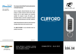
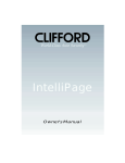
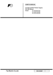
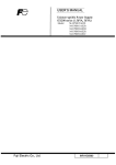
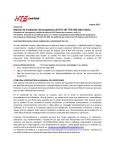
APS-700
Installation Guide
Remote Control Security System
With Pager/Satellite Control Interface
Installation Instructions
Kit Contents
APS-700 Control Module
4 Channel Code Learning Receiver
2 Three Button Anti-Code Grabbing Transmitters
Six Tone Multi-Tone Siren
Starter Inhibit Relay w/Socket
Main Wiring Harness
Auxiliary Wiring Harness
Plug In Valet
Plug In 2/Pin Door Lock Harness
Plug In LED
2 Pin Accessory VSS Harness
4 Pin Shock Sensor Harness
Plug In Two Stage Shock Sensor
Pin Switch Hardware Bag
Installation Guide
Owners Guide
Prestige Platinum Warranty
Consumer Activation Form
Window Warning Decals
The APS-700 is a full featured security system with on board paging technology that provides the consumer a direct link to
their vehicle from anywhere in the world. This patent pending technology allows the user to operate the vehicle from any
land or mobile telephone. The vehicle's owner can command the security system to arm or disarm, release the trunk, start
the vehicle, and in case of a carjacking, can put the APS-700 in a special carjack mode that will flash the lights, sound the
siren and prevent restarting of the vehicle.
NOTE: Many of the paging features available to the consumer are part of the alarm functions of the unit. Features such as
lock / unlock, arm, disarm, carjack, and reset will be available after installation with no special consideration on the part of
the installing technician. There are three additional auxiliary outputs accessible by paging the APS-700 that will require
some consideration. The Alarm's receiver channels 2, 3, and 4, are the same as paging auxiliary functions 1, 2, and 3.
These outputs, when connected to the vehicle, MUST BE NOTED on the Owners Guide, Rear Page Of This Manual and on
the Paging Registration Guide. Additionally, access from the RF transmitter may provide a latched output from these
channels however access from the paging network will only provide a 800 ms pulsed output. Please note this as it may
effect the options that you connect to these output wires. Each wire is referenced individually later in this manual.
MOUNTING THE COMPONENTS:
CONTROL MODULE:
Select a mounting location inside the passenger compartment up and behind the dashboard. The mounting location
selected must consider routing of the antenna to allow it to be fully extended, away from metal which may shield it, and as
high as possible to insure the best RF reception and operating range. Additional consideration should be made to keep the
control module away from on-board computers. These devices have local oscillators which may produce RF and inhibit or
limit reception.
Be certain that the chosen location will not interfere with proper operation of the vehicle. Avoid mounting the module to or
routing the wiring around the steering shaft/column, as the module's wiring may wrap around or block the steering wheel
preventing proper control of the vehicle. Secure the module in the chosen location using cable ties or screws as necessary.
Do Not Mount The Module In The Engine Compartment, it is not waterproof.
SIREN:
Select a location in the engine compartment that is not accessible from below the vehicle. The selected location must be
clear of hot or moving parts within the engine compartment. The siren must be pointed downward to prevent water retention
and the flared end must be pointed away and out of the engine compartment for maximum sound distribution. Before
securing the siren, check behind your chosen location to assure that the mounting screws will not penetrate any factory
wiring or fluid lines. Secure the siren mounting bracket using #8 self taping screws or, by first using the mounting bracket as
a template, scribe or mark the three bracket mounting holes. Drill the three marked holes using a 1/8" drill bit, then mount
the siren using #8 sheet metal screws.
HOOD AND TRUNK PIN SWITCHES:
The pin switches included in this package are intended for protecting the hood and trunk areas of the vehicle. In all cases,
the switch must be mounted to a grounded metal surface. When the pin switch is activated, (hood/trunk open), it will supply
a ground to the input wire activating the alarm. Mount the switches under the hood and in the trunk compartment in
locations away from water drain paths. If necessary, the included brackets may be used to move the switch away from rain
gutters or allow mounting to the firewall behind the hood seal. In both cases the switch must be set up to allow the hood or
trunk to depress the switch at least 1/4 inch when the hood or trunk is closed and fully extended when the hood or trunk is
opened. For direct mounting, a 1/4 inch hole must be drilled. Carefully check behind the chosen location to insure the drill
will not penetrate any existing factory wiring or fluid lines. Drill a 1/4" hole in the desired location and thread the pin switch
into it using a 7/16" nut driver or deep well socket. If using the mounting bracket, first secure the bracket to the desired
location and secure the pin switch in the pre-threaded mounting bracket hole.
DASH MOUNTED L.E.D:
The small red LED included in the kit will serve as a visual indicator of the alarm's status and provide a visual deterrent to
a potential thief. The LED also provides important feed back information during the transmitter and feature program modes.
The LED should be installed in the dash in an area highly visible so that it may be seen from the driver's seat as well as from
outside the vehicle. Inspect behind the chosen location to insure that the drill will not penetrate any existing factory wiring
or fluid lines. Carefully drill a 1/4" hole in the desired location and pass the connector end of the LED through the hole and
toward the control module. Press the LED firmly into place until it is fully seated in the mounting hole.
2
VALET/PROGRAM SWITCH:
Select a mounting location that is easily accessible to the operator of the vehicle. The switch can be mounted to the lower
dash panel in the driver's area. Inspect behind the chosen location to insure that adequate clearance is allowed for the
body of the switch, as well that the drill will not penetrate any existing factory wiring or fluid lines. Drill a 1/4" hole in the
desired location and mount the switch by passing it through the panel from the underside. Secure the switch using the nut,
star washer, and on/off face plate. It is suggested that the switch be oriented to allow the on position to be up toward the
driver and the off position to be down or away from the driver. Route the switches's connector toward the control module.
SHOCK SENSOR:
Select a centrally located, solid mounting surface for the shock sensor that will allow consistent operation from all areas of
the vehicle. The selected location must be within 18" of the control module to allow routing and connecting of the 4 pin
harness. Secure the shock sensor to the chosen location using two #8 self taping sheet metal screws. The sensor can
also be secured to an existing dash brace using cable tie straps. Whichever mounting method is used, be sure to allow
access to the sensitivity adjustment potentiometer for use later in the installation.
STARTER INHIBIT RELAY:
Select a mounting location within 12" of the ignition switches low current start solenoid wire. Secure the relay to an existing
harness in the chosen location using a cable tie around the relay's wiring harness. Caution! Do not wire tie the metal
bracket to an existing wiring harness as vibration may cause chaffing and shorting damaging the factory wiring. If an
existing harness is not available then secure the relay's metal mounting tab to an under dash metal brace with a #8 self
taping sheet metal screw. Wire the relay as per the diagram found later in this manual.
NOTE: Before connecting the module, pre-select all the wires in the vehicle. First, using a digital VOM, test all the wires
you intend to connect to in the vehicle. Disconnect the vehicle battery and complete all wiring to the vehicle before
connecting the control module to the harness connectors. This will prevent the pager from activating during the installation. Once all wiring is complete and the module is connected, disarm the unit immediately before proceeding with the
testing of the unit.
WIRING THE CONTROL MODULE:
8 Pin Main Wiring Harness
Red w/White Trace: + 12 volts Battery Source
Connect this wire to a constant + 12 VDC source found at the vehicles ignition switch using the 5 Amp fuse and holder
provided.
Orange Wire: Ground When Armed Output
This wire provides a 300 mA ground output when the alarm circuit is armed to control the starter inhibit relay. Connect the
Orange wire to terminal #86 (orange wire) of the previously installed starter interrupt relay. Connect terminal #85 (red wire)
of the relay to an ignition wire in the vehicle that is live when the ignition switch is turned to the on and start positions and
off when the key is off. Locate and cut the low current start solenoid wire found at the vehicles ignition switch harness. This
wire will have + 12 volts when the ignition key is moved to the start (crank) position and will have 0 volts in all other key
positions. Connect one side of the cut wire to terminal #87a ( Black wire) of the relay. Connect the other side of the cut wire
to terminal #30 (White/Black wire) of the relay.
Green w/ White trace Wire: Entry Illumination Ground Output
This wire provides a 30 second ground output (300 mA Max.) whenever the remote is used to disarm the alarm or to unlock
the doors and provides a continuous pulsed output whenever the alarm is triggered. This wire should be connected to an
external relay and wired to the vehicles interior entry lighting whenever the optional Interior Illumination circuit is desired.
Dark Blue Wire: Delayed 300mA Pulsed Channel 2 Output
The Dark Blue channel 2 output wire supplies a 300mA ground pulsed output whenever channel two of the receiver is
accessed. Pressing the pre-programmed transmitter button for three seconds will access channel two. Channel 2 is also
considered auxiliary output 1 available by satellite paging to the vehicle. Whether accessing this output form the key chain
transmitter or via the satellite paging network, the Dark Blue wire will provide a 800ms pulsed ground output. This is a low
current output and must be connected to a relay to supply power to the trunk release or the circuit you wish to control.
Connect the Dark Blue wire to terminal # 86 of a VF45F11 P&B relay or equivalent. Connect terminal # 85 of the relay to
a fused + 12 volt battery source. Connect the common, normally open, and normally closed contacts of the relay to
perform the selected function of channel 2.
3
White w/ Black Trace Wire: Positive (+) Siren Output
This is the positive siren feed wire. Route this wire through a grommet in the firewall to the siren location. Connect the White
w/ Black Trace wire to the Red wire of the Siren. Secure the Black wire of the Siren to a known chassis ground or solid clean
metal surface.
Black Wire: Chassis Ground Source
Connect the Black wire to a known vehicle ground source or to a solid clean metal part of the chassis. Be certain to remove any
paint or grease and secure this wire with a self taping screw and ring terminal.
2 White Wires: Low Current Directional Light Flash Output Wires
The APS-700 provides two different and distinguishable light flash patterns. During normal arming and disarming, a standard
alarm flash pattern is observed. When the unit is placed in a theft mode, from the paging network, a special light flash pattern,
(S.O.S.) is observed. This highly recognizable and very different flash pattern is necessary to distinguish a vehicle theft from a
vehicle break-in.
You must consider that the parking lights may be in the on position if the vehicle is carjacked or stolen, In this application
special consideration for wiring of the light flash circuit must be made. Audiovox advises that the directional element of the
bulbs be used in all cases to insure that this light flash pattern will be operational in all situations.
The two White wires provide, ( 300mA) low current pulsed ground outputs to control the light flash patterns. In all cases relays
must be used.
Three of the most common directional circuits available in today's vehicles are:
1. Four Independent Bulbs, LF,LR,RF,RR.
2. Left Front And Rear Common / Right Front And Rear Common
3. Rear Common Front Independent.
Wiring for these circuits are shown later in this manual.
10 Pin Mini Wiring Harness:
Light Blue Wire: Low Current Latching Output / Channel 4
The Light Blue, channel 4 output wire latches to ground via an independent RF channel from the keychain transmitter. Channel
4 is also considered the Auxiliary 3 output available by satellite paging to the vehicle. When operating this channel from the
paging network, this output will be a pulsed 800ms output. Consider this when connecting to an accessory in the vehicle. Be
certain to list the function of this output in the Owners Manual, Owners Paging Manual, and on the rear page of this manual.
This wire provides an immediate ground signal, and remains grounded as long as the transmitter button(s) is held. This is a low
current (300mA) output and in all cases will be used to drive an external relay coil. To use the Light Blue wire, connect it to
terminal # 86 of a P&BVF45F11 or equivalent relay. Connect terminal # 85 of the relay to a fused + 12 volt battery source.
Connect terminal # 30 of the relay to ground or a fused + 12 volt battery source, dependent upon the device in the vehicle you
wish to control. Connect terminal # 87 to the vehicle's switched device's control wire.
Dark Green w/ Black Trace Wire: low Current Latching Output / Channel 3
The Dark Green w/ Black trace, channel 3 output wire latches to ground via an independent RF channel from the keychain
transmitter. Channel 3 is also considered the Auxiliary 2 output available by satellite paging to the vehicle. When operating this
channel from the paging network, this output will be a pulsed 800ms output. Consider this when connecting to an accessory in
the vehicle. Be certain to list the function of this output in the Owners Manual, Owners Paging Manual, and on the rear page of
this manual.
This wire provides an immediate ground signal, and remains grounded as long as the transmitter button(s) is held. This is a low
current (300mA) output and in all cases will be used to drive an external relay coil. To use the Dark Green w/ Black Trace wire,
connect it to terminal # 86 of a P&BVF45F11 or equivalent relay. Connect terminal # 85 of the relay to a fused + 12 volt battery
source. Connect terminal # 30 of the relay to ground or a fused + 12 volt source, dependent upon the device in the vehicle you
wish to control. Connect terminal # 87 to the vehicle's switched device's control wire.
Black w/ White Trace Wire: 300mA Ground Horn Output
The Black w/ White Trace wire will provide a pulsed ground output which can be used to sound the vehicle's horn. This is a low
current (300mA) output and must be connected to a relay for proper operation. Most vehicles have a horn relay connected to
the horn switch. If the existing relay requires less than 300 mA then direct connection to the horn wire is possible. If the vehicle
horn does not switch a existing low current relay or if the horn circuit is + 12 volts switched, you must connect the Black w/ White
Trace wire to a external relay coil. When connecting to an external relay, connect the Black w/ White Trace wire to terminal #
86 of a P&B VF45F11 or equivalent relay. Connect terminal # 85 to a fused +12 volt battery source. Arrange terminals # 30 &
# 87 to switch ground or + 12 volts as necessary for the horn circuit you are connecting to.
Orange w/ White Trace Wire: Low Current Ground When Disarmed Output
The Orange w/ White Trace wire provides a ground output when the security system is disarmed. This low current (300mA),
output may be used to control a normally open Starter Inhibit Circuit where desired. To use the Orange w/ White Trace wire,
Connect the Orange w/ White Trace wire to terminal # 86 of a P&BVF45F11 or equivalent relay. Connect terminal # 85 of the
relay to an ignition wire in the vehicle that has + 12 volts when the ignition key is in the on and start positions and has 0 volts in
the off and accessory positions. Locate and cut the low current start solenoid wire found at the vehicles ignition switch harness.
Connect terminal # 30 of the relay to the ignition switch side of the cut wire. Connect terminal # 87 of the relay to the starter side
of the cut wire.
NOTE: This normally open starter cut relay arrangement will prevent the vehicle from starting if the control module or wiring to
the control module is disconnected or removed. Audiovox does not recommend the use of this circuit to interrupt anything but
the starting circuit of the vehicle.
4
Dark Green Wire: (-) Instant Trigger Zone 2
The Dark Green wire is the instant on ground trigger input wire. This wire must be connected to the hood and trunk pin
switches previously installed. Note: This wire will be shunted when remote control channel 2 is accessed, (trunk release).
This wire will remain shunted all the while there is ground present, and for 5 seconds after the ground is removed. This allows
the operator to open the trunk via the remote transmitter without having to first disarm the alarm system.
Brown Wire: (-) Negative Door Trigger Input
If the vehicle's door courtesy light switches ground when the door is opened, (Most GMs and Imports), you must connect this
wire to the negative output from one of the vehicle's door pin switches. In most cases the Brown wire will need to be connected
to only one door switch no matter how many doors the vehicle has as most door lighting circuits are wired in parallel.
Purple Wire: (+) Positive Door Trigger Input
If the vehicle's door courtesy light switches + 12 volts when the door is opened, (Most Fords and some Imports), you must
connect this wire to the positive output from one of the vehicle's door pin switches. In most cases, the Purple wire will need to
be connected to only one door switch no matter how many doors the vehicle has as most door lighting circuits are wired in
parallel.
Yellow Wire: (+) 12 Volts Ignition Switch Input
Connect this wire to a source in the vehicle that is live when the ignition switch is in the on and start positions, and has 0 volts
in all other switch positions.
White w/ Blue Trace Wire: Low Current (-) Ground Headlight Output
The White w/ Blue Trace wire is provided to operate the optional headlamp illumination feature of the system. This is a low
current (300mA) output and must be connected to an external relay to control the high current switching circuit of the vehicle's
headlamps. To use this option, Connect the White /w Blue Trace wire to terminal # 86 of a P&B VF45F11 relay or equivalent.
Connect Terminals #85 and # 30 to a fused + 12 Volts source with a current capability equal to or in excess of the factory
headlamp fuse. Connect terminal # 87 of the relay to the switched + 12 volt wire feeding the vehicle's headlamp circuit.
NOTE: For ground switched headlamp circuits, Connect the White /w Blue Trace wire to terminal # 86 of a P&B VF45F11
relay or equivalent. Connect Terminal #85 to a fused + 12 Volts source. Connect terminal # 30 to a clean chassis ground.
Connect terminal # 87 to the ground switched headlamp control wire in the vehicle.
Light Green Wire: (-) Instant Trigger Zone 1
This is a instant on ground trigger input intended for the connection of optional triggering devices. The ground trigger output
wire of motion detectors, microwave detectors, or glass break detectors, can be connected to this Light Green trigger input
wire.
2 Pin Valet/Program Switch: (Blue Connector)
The Black & Grey twin lead wires loaded in the two pin blue connector are the ground supply and program/valet input of the
APS-700. When the Grey wire is grounded, under certain conditions, the unit will enter the valet mode. When the Grey wire
is sequentially grounded under other conditions, the unit will enter the various program modes. Route the twin lead Black and
Grey wires from the valet/Program switch to the APS-700 and plug the two pin connector into the mating blue connector shell
of the control module. Refer to the remote programming, feature programming and function programming shown later in this
installation guide for operation of the valet/program switch.
2 Pin Door Lock/Unlock Harness: (White Connector)
The Red & Green Door Lock/Unlock output wires provide either a pulsed ground or pulsed + 12 volts to control the vehicle door
lock / unlock circuits. The output of these wires has a maximum switching capability of 300mA. Many vehicles today have
factory door lock relays which can be connected directly to these outputs, however always confirm that the factory relays in
your particular vehicle do not exceed the rated 300mA output of the unit's door lock/unlock circuit. Plug the two pin connector
of the door lock/unlock harness into the mating connector shell of the control module. Determine the door lock circuit of the
vehicle you are working on and wire according to the diagrams shown.
3 Wire Ground Switched Door Lock Circuits:
In this application, the Red wire of the two pin harness provides a ground pulse during the arming sequence, or pulsed ground
lock output. Connect the Red wire to the low current ground signal from the factory door lock switch to the factory door lock
relay.
The Green wire of the two pin harness provides a ground pulse during the disarming sequence, or pulsed ground unlock
output. Connect the Green wire to the low current ground signal from the factory door unlock switch to the factory door unlock
relay.
3 Wire Positive Switched Door Locks:
In this application, the Red wire of the two pin harness provides a + 12 volt pulse during the disarming sequence, or pulsed
12 volt unlock output. Connect the Red wire to the low current 12 volt signal from the factory door unlock switch to the factory
door unlock relay.
The Green wire of the two pin harness provides a + 12 volt pulse during the arming sequence, or pulsed 12 volts lock output.
Connect the Green wire to the low current 12 volt signal from the factory door lock switch to the factory door lock relay.
Note: For connection to Four Wire Polarity Reversal, 5 Wire Alternating 12 Volts, And All Other Door Lock Circuits the
Audiovox AS-9159 Door Lock Interface, (or equivalent 30 A automotive Relay must be used. Refer to the Audiovox Door Lock
Wiring Supplement for proper wiring of these circuits.
5
2 Pin Auxiliary Harness: (Red Connector)
The two pin auxiliary connector is used to control vehicle shut down from a paging theft command. See supplement for wiring
information.
Connecting The Dash Mounted LED:
Plug the two pin white connector from the previously installed LED into the mating two pin white female connector shell of the
control module.
Connecting The APS-700 Module:
Re-connect the vehicle's battery then plug the main and mini connectors into the mating connector shells of the control module.
Immediately disarm the system with the hand-held transmitter to prevent the pager board from activating.
Programming The APS-700:
The transmitter programming is pre-set from the factory so that Button 1 controls Arm/Disarm, Button 2 controls Channel 2
output, Button 3 controls Channel 3 output, Button 2&3 controls Channel 4. If the consumer wishes a different configuration,
see separate transmitter programming guide packaged with this kit.
Keep in mind that Alarm Channel 2 = Pager Auxiliary output 1, Alarm Channel 3 = Pager Auxiliary output 2, and Alarm Channel
4 = Pager Auxiliary output 3.
The alarm features are pre-programmed at the factory for the most common configuration. If you wish to change any of these
settings, refer to the Alarm Selectable Feature programming later in this manual.
Testing The APS-700:
Testing The Unit's Outputs Via The On Board Test Switch:
IMPORTANT! Do not fax the activation sheet until the system has been thoroughly tested, and all functions that have been
connected are operating properly.
Note: Make sure that you have at least 1 window open and the keys out of the vehicle before operating the test switch or the
paging test sequence.
1. Slide open the access door of the module case and locate the push button test switch.
2. Using the rubber end of a pencil eraser, depress the push button one time.
The APS-700 will simulate the following events sequencing through each command with a 5 second interval between each
sequence:
A. Auxiliary Output 1
C. Auxiliary Output 3
E. Arm Alarm
G. Carjack
B. Auxiliary Output 2
D. Door Unlock
F. Disarm Alarm
H. Reset All
After the push button test is complete and you've confirmed the proper operation of all functions, proceed with the Radio
Frequency Test.
3. From a touch tone phone, dial the appropriate test phone number and request a test signal for the serial number of the unit
being tested.
4. The signal will be received at the vehicle and the following sequence of events will be observed. There will be a 5 second
interval between each sequence:
A. Auxiliary Output 1
C. Auxiliary Output 3
E. Arm Alarm
G. Carjack
B. Auxiliary Output 2
D. Door Unlock
F. Disarm Alarm
H. Reset All
After confirming that all options connected to the APS-700 are operating properly, complete the activation form supplied with
the unit. Make sure all selectable auxiliary options are clearly identified on the application sheet, owners manual and on the
last page of this manual.
NOTE: After verifying that the RF test was successful, you will need to specifically test the theft / hijack command for two
functions.
1. During this portion of the test, the vehicle must be running. From a touch tone phone, dial the appropriate test phone number
and request a theft signal for the serial number of the unit being tested. Once the signal is received, turn the engine off.
Attempt to restart the vehicle. If the engine starts, check your connections to the starter inhibit relay. After verifying that the
engine will not start after receiving the RF theft command, reset the system by calling the test telephone number and request
a reset command for the unit being tested.
2. During this portion of the test, be sure that the vehicle is started and moving. You must confirm that the vehicle will not shut
down until 5 seconds after the vehicle comes to a complete stop. This will confirm that the VSS connection and ignition
interrupt circuits are operating properly. Failure to complete this portion of the test could result injury to the occupant(s) of
the vehicle. This test may require the use of an assistant to place the call if you do not have a cellular phone available.
While driving above 3 MPH, call the test telephone number and request a theft/hijack signal be sent. Once the signal has
been received, wait 10 seconds, then allow the vehicle to come to a complete stop. After 5 seconds, the vehicle should stall.
If the vehicle continues to run, you will need to recheck your connections to the ignition control relay. First call the test center
and request a reset, confirm your connections to the VSS circuit and the ignition control relay, then repeat the above test until
the vehicle stalls as described. Upon completion call the test center and request a reset.
6
Connecting And Adjusting The Shock Sensor:
Route the 4 pin cable from the previously installed shock sensor to the control module. Plug it into the mating 4 pin white
connector shell located along side the 8 pin main harness connector of the control unit.
Pre- adjust the previously installed Shock Sensor by first accessing the potentiometer setting screw and carefully turn this
adjustment all the way counterclockwise. Now Turn the adjuster clockwise to the first notch on the module case.
CAUTION! Use caution when striking the vehicle and around the glass panels. Impact tolerances of vehicle glass differs from
vehicle to vehicle. This test can also be made by striking the vehicle bumpers providing you consider the amount of force
required to break a window.
Exit the vehicle, close all doors, hood and trunk and arm the alarm system.
Firmly strike the windshield pillar with the open palm of your hand. If the alarm system triggers, disarm then re-arm the
system and make the same test on the rear window support. If the system triggers, no further adjustment is necessary.
If in the above test the sensor did not trigger the alarm system, carefully move the adjustment potentiometer in a clockwise
direction and re-test in the same manner until the desired results are achieved.
Confirm the Alarm's operation by arming the alarm, testing an entry point then disarming. Follow this sequence until all
protected areas have been tested. While testing, observe the operation of the parking lights for proper operation, confirm that
the siren chirp patterns for arm, disarm, disarm after intrusion and arm while a door is open are operating properly. If
headlight illumination is used, check to insure proper operation.
ALARM SELECTABLE FEATURES
RF Programmable Features:
Feature Selection
1 Chirp
2 Chirp
Default
First
1 Second Door Locks
3.5 Second Door Lock
1 Second
Second
Auto Lock On
Auto Lock Off
Auto Lock Off
Third
Auto Unlock On
Auto Unlock Off
Auto Unlock Off
Fourth
Headlight Output On
Headlight Output Off
Headlights On
Fifth
Passive Door Locks
Active Door Locks
Active Door Locks
Sixth
Passive Arming
Active Arming
Passive Arming
To Program The Alarm's Selectable Features:
Action
Turn the ignition switch on
Flip the valet/program switch on then off 3 times
Within 3 seconds, turn the ignition switch off,
then on
Press transmitter button 1 to change.
Or
Flip valet/program switch on then off
Second Press transmitter button 1 to change.
Or
Flip valet/program switch on then off
Press transmitter button 1 to change.
Third
Or
Flip valet/program switch on then off
Fourth Press transmitter button 1 to change.
Or
Flip valet/program switch on then off
Press transmitter button 1 to change.
Fifh
Or
Flip valet/program switch on then off
Press transmitter button 1 to change.
Sixth
Or
Flip valet/program switch on then off
Or
Turn ignition switch off.
First
System Response
LED Flash Pattern
No Response
1 Chirp-LED 1 Flash
Short Chirp, then Long Chirp
1 Chirp = 1 second Locks
2 Chirps = 3.5 second Locks
1 Flash Pause etc.
2 Chirps = auto locks off
1 Chirp = auto locks on
2 Falsh Pause etc.
2 Chirps = auto unlock off
1 Chirp = auto unlock on
3 Flash Pause etc.
1 Chirps = headlight o/p On
2 Chirp = headlight o/p Off
4 Flash Pause etc.
2 Chirps = Active Locks
1 Chirp = Passive Locks
5 Flash Pause etc.
1 Chirp = passive arming
2 Chirps = active arming
6 Flash Pause ect.
Exit Program Mode
Exit Program Mode
NOTE: Once you've entered the program mode DO NOT allow more than 15 seconds to pass between steps, or the programming mode will be terminated.
7
LEFT FRONT & REAR COMMON
RIGHT FRONT & REAR COMMON
RIGHT
SIDE
8
THE FOLLOWING OPTIONS HAVE BEEN INSTALLED AND ARE CONNECTED TO THE ALARM
AND PAGER OUTPUTS AS SHOWN
ALARM
PAGER
CHANNEL 2
CHANNEL 3
CHANNEL 4
AUXILIARY OUTPUT 1 IS CONNECTED TO
AUXILIARY OUTPUT 2 IS CONNECTED TO
AUXILIARY OUTPUT 3 IS CONNECTED TO
PRODUCT INFORMATION
SERIAL #
COUNTRY CODE
DLR/DIST ID#
INSTALLATION DATE
VEHICLE INFORMATION
VEHICLE YEAR
VEHICLE MFG.
VEHICLE COLOR
LICENSE PLATE#
VIN#
9
VEHICLE MOD.
SHOCK SENSOR
RED, BLACK, BLUE AND GREEN WIRES
TO PLUG IN SHOCK SENSOR
+12 VOLT BATTERY
CONNECT TO A +12 VOLTS
FULL TIME BATTERY SOURCE
RED w/WHITE
MODULE
APS-700
Cut
Existing Low Current
To +12 Volt
IGN. / CRANK
Start Solenoid
Wire
ORANGE
RED
LOW CURRENT OUTPUT
LEFT SIDE LIGHT FLASHER
SEE SPECIAL NOTES REGARDING
APPLICATION
WHITE
GREEN w/WHITE
10
To Entry Illumination
Wire of Vehicle
Vehicle's Entry Lighting Circuit Switch +12 Volts?
Connect To a Fused +12 Volts Source
LOW CURRENT OUTPUT
RIGHT SIDE LIGHT FLASHER
SEE SPECIAL NOTES REGARDING
APPLICATION
WHITE
Vehicle's Entry Lighting Circuit Switch Ground?
Connect to Chassis Ground
Clean Non-Painted
Metal Surface
To Fused
Battery Source
DARK BLUE
BLACK
CHASSIS GROUND
CHANNEL 2 / AUXILIARY 1 OUTPUT
To Vehicle Trunk Release
Solenoid
RED
WHTIE w/BLACK
SIREN
Vehicle's Trunk Release Circuit Switch
+12 Volts?
Connect to a Fused +12 Volts Source
Vehicle's Trunk Release Circuit Switch
Ground?
Connect to Chassis Ground
To Fused
Battery Source
BLACK
APS - 700
DOOR LOCK OUTPUTS
(+) LOCK PULSE
(-) UNLOCK PULSE
CAUTION:
Data Connection For
Upgrade Vehicle
Tracking Module Only
GREEN
(+) UNLOCK PULSE
(-) LOCK PULSE
RED
LED
RED
VSS IGNITION CONTROL
SEE SPECIAL NOTE
CONCERNING THIS
APPLICATION
VALET/PROGRAM
SWITCH
BLACK
BLUE
RED
BLACK
GRAY
ZONE 1
Connect to Optional
Negative Triggering Devices
CHANNEL 4 /AUXILIARY 3
Negative Latching Output For
Optional Window Roll-Up or
Remote Start
CHANNEL 3/AUXILIARY 2
Negative Latching Output For
Optional AccessoryWindow
Roll-Up or Remote Start
HORN OUTPUT
Connect to Negative
Low Current Wire From
Horn Switch
GROUND WHEN
DISARMED OUTPUT
Connect To Relay For
Normally Opened
Starter-Cut Feature
LIGHT BLUE
LIGHT GREEN
HEADLIGHT OUTPUT
30 Second Output During
Arm and Disarm.
Relay Required
WHITE w/BLUE
GREEN w/BLACK
IGNITION SOURCE
Connect to a Source that has
+12 with the Key in the ON
and Start Modes
BLACK w/WHITE
YELLOW
ORANGE w/WHITE
PURPLE (DOOR +)
HOOD/TRUNK
PIN SWITCH
NEGATIVE TRIGGER
DARK GREEN
BROWN (DOOR -)
11
FROM DOME
LIGHT FUSE
VSS WIRING SUPPLEMENT
The two pin auxiliary harness with the red connector shell provides a input signal to the control module from the vehicle's
Speed Sensor ( VSS), and provides a low current ground switched output to control a shut down relay.
The relay can be used to interrupt any circuit in the vehicle which will cause the vehicle's engine to stop running.
Typically the contacts of this relay can be used to interrupt the primary (+) feed wire of the ignition coil or the positive feed
wire controlling the electric fuel pump.
Whichever circuit you choose to interrupt, be certain that you fully test the operation of the shut down circuit as described
on page 6 of the installation manual.
TO INSTALL THE VSS SHUT DOWN CIRCUIT:
1. Locate the VSS signal wire found in the vehicle at the ECM or the signal generator.
2. Connect the Black wire of the two pin connector to the previously located VSS signal wire.
3. Connect the Red wire of the two pin connector to terminal #86 of a P&B VF45F11 or equivalent 12 volt automotive
relay.
4. Connect terminal # 85 of the relay to a + 12 volt ignition source. This wire will have + 12 volts with the ignition
switch turned to the on and start positions and will have 0 volts with the ignition switch in the off or accessory positions.
5. Connect the common contact (#30), and normally closed contact (87a) to the circuit you wish to interrupt as shown
below.
NOTE: Be certain to follow the test procedure as outlined on page 6 of the installation manual.
Form No. 128-5030C
12
Modelo APS-700
Guía de instalación
Sistema de seguridad a control remoto con sistema
de aviso/interfaz de control de satélite
Instrucciones de instalación
Contenido del kit:
Módulo de control APS-700
Receptor con captación de código de 4 canales
2 transmisores de 3 botones con escalonamiento de frecuencias de código
Sirena de seis tonos
Relé para bloquear el arranque con casquillo adaptador
Arnés de cableado principal
Arnés de cableado auxiliar
Connecte el Valet
Arnés de trabado de puertas con dos clavijas enchufables
Indicador LED enchufable
Arnés del VSS para accesorios de 2 clavijas
Arnés para el detector de choque con 4 clavijas
Detector de choque enchufable de dos etapas
Bolsa con piezas y componentes para interruptores de clavija
Guía de instalación
Guía para el propietario
Garantía Platinum Prestige
Forma para Activacción para el Consumidor
Calcomanías de advertencia para las ventanillas
El sistema APS 700 es un sistema de seguridad de múltiples funciones con la tecnología de aviso incorporada que
proporciona al consumidor en enlace directo con su vehículo desde cualquier lugar del mundo. Esta nueva tecnología,
cuya patente se encuentra pendiente, permite al usuario operar el vehículo desde cualquier teléfono común o móvil. El
propietario del vehículo puede enviar una orden al sistema de seguridad para activarlo o desactivarlo, desenganchar el
baúl, arrancar el vehículo y, en el caso de un intento de robo del automóvil, puede poner al APS-700 en un modo especial
anti-robo que hará destellar las luces, sonar la bocina e impedir que se arranque el vehículo.
NOTA: Muchas de las funciones de aviso que tiene el consumidor forman parte de las funciones de alarma de la unidad.
Funciones tales como trabar / destrabar, activar, desactivar, anti- robo y reposición podrán usarse después de la instalación
sin consideración especial alguna de parte del técnico de instalación. Hay tres otras salidas auxiliares a las que se puede
tener acceso mediante un llamado al APS-700 que requerirá algo de atención especial. Los canales 2, 3, y 4 de recepción
de la alarma son iguales que las funciones auxiliares de aviso 1, 2 y 3. Estas salidas, al estar conectadas al vehículo,
TIENEN QUE ESTAR INDICADAS en la Guía del Propietario, la página de atrás de este manual y la Guía de inscripción
del sistema de aviso. Además, el acceso del transmisor RF puede proporcionar una salida bloqueada de estos canales,
pero el acceso de la red del sistema de aviso proporcionará solamente una salida pulsada de 800 ms. Sírvase tener en
cuenta esto dado que puede llegar a afectar las opciones que conecte a estos cables de salida. Cada cable tiene una
referencia individual más adelante en este manual.
INSTALACIÓN DE LOS COMPONENTES PRINCIPALES
MÓDULO DE CONTROL:
Elija un lugar de montaje adentro del compartimiento del pasajero, arriba y detrás del tablero de instrumentos. El lugar de
montaje elegido debe tener en cuenta el recorrido de la antena para permitir que se pueda extender totalmente, lejos de
partes metálicas que puedan escudarla, y lo más alto posible para asegurar la mejor recepción de RF y rango operativo.
Se debe tener mucho cuidado también para mantener el módulo de control alejado de las computadoras que tenga el
vehículo. Estos aparatos tiene osciladores locales que pueden producir RF y bloquear o limitar la recepción.
Asegúrese de que el lugar elegido no interfiera con la operación adecuada del vehículo. Evite montar el módulo o encaminar
los cables alrededor del eje/la columna de la dirección, dado que el módulo o los cables pueden estorbar o bloquear el
volante e impedir el control del vehículo. Asegure el módulo en el lugar elegido usando amarres para cables o tornillos si
es necesario.No monte el módulo en el compartimiento del motor dado que no es impermeable.
SIRENA:
Elija un lugar en el compartimiento del motor que no sea accesible desde abajo del vehículo. El lugar elegido debe estar
alejado o separado de las piezas calientes o móviles que hay en el compartimiento del motor. La sirena tiene que estar
apuntando hacia abajo para evitar la retención de agua y el extremo ancho debe apuntar hacia afuera del compartimiento
del motor para lograr una máxima distribución del sonido. Antes de fijar la sirena, fíjese detrás del lugar elegido para
asegurarse de que los tornillos de montajes no penetren en ningún cable instalado en fábrica o en los conductos de los
líquidos o fluidos. Sujete el soporte de montaje de la sirena con tornillos #8, o bien use primero el soporte de montaje como
plantilla, y marque los tres orificios para el soporte de montaje. Perfore los tres orificios marcados con una mecha de
taladro de 1/8 pulgadas y luego coloque la sirena usando tornillos de metal #8.
INTERRUPTORES DE CLAVIJA PARA EL CAPÓ Y BAÚL:
Los interruptores de clavija que se incluyen en este paquete tienen por objeto proteger el capó y el baúl del vehículo. En
todos los casos, se debe montar el interruptor en una superficie metálica conectada a tierra. Cuando se activa el interruptor
de clavija (se abre el capó / baúl), proporcionará una conexión a tierra al cable de entrada que activa la alarma. Además,
se requiere el interruptor del capó para apagar la unidad de arranque remoto. Si se está trabajando en el vehículo, este
interruptor de capó previene la activación del arranque remoto aun cuando se emita el comando RF para arrancar. Este
interruptor debe instalarse en todas las aplicaciones. Si no se lo instala, se puede provocar lesiones personales o daños
físicos. Instale los interruptores en el capó y el baúl lejos de los desagües de agua. Si es necesario, se puede usar los
soportes provistos para mover al interruptor lejos de las canaletas de agua o permitir el montaje en el muro contrafuego
detrás del sellante del capó. En ambos casos, se debe colocar el interruptor como para permitir que el capó o la puerta del
baúl oprima el interruptor ¼ de pulgada, por lo menos, al cerrar el capó o el baúl y que quede totalmente extendido cuando
se abre el capó o el baúl. Para un montaje directo, se debe perforar un orificio de ¼ pulgada. Fíjese bien detrás del lugar
elegido para asegurarse de que el taladro no penetre ningún cable o conducto para líquido que ya venga instalado de
fábrica. Perfore un orificio de ¼ pulgada en el lugar deseado y coloque el interruptor de clavija usando una llave para
tuercas de 7/16 pulg. o un encastre profundo. Si usa el soporte de montaje, coloque primero el soporte en el lugar deseado
e instale el interruptor de clavija en el orificio del soporte de montaje roscado.
INDICADOR L.E.D. PARA EL TABLERO DE INSTRUMENTOS:
El pequeño indicador LED rojo que viene en el kit sirve como indicador visual del estado de la alarma y proporciona una
elemento de disuasión visual para un posible ladrón. El indicador LED proporciona también información importante durante
los modos de programación del transmisor y de las funciones. Se debe instalar el LED en el tablero de instrumentos, en un
lugar que sea bien visible para que se pueda ver fácilmente desde el asiento del conductor así como desde afuera del
vehículo. Fíjese bien detrás del lugar elegido para asegurarse de que el taladro no penetre ningún cable o conducto para
líquidos o fluidos que ya venga instalado de fábrica. Perfore un orificio de ¼ pulgada en el lugar deseado y pase el
extremos del conector del LED por el orificio y hacia el módulo de control. Apriete con firmeza el LED hasta que quede bien
asentado en el orificio de montaje.
14
INTERRUPTOR VALET / PROGRAMACIÓN :
Elija un lugar de montaje al que el operador del vehículo tenga fácil acceso. Se puede montar el interruptor en el panel
inferior del tablero en el área del conductor. Asegúrese de fijarse detrás del tablero para comprobar si hay el suficiente
espacio para la caja del interruptor y para confirmar que el taladro no vaya a dañar ninguno de los componentes existentes
cuando pase a través del tablero de instrumentos. Perfore un orificio de ¼ pulgadas en el lugar deseado e instale el
interruptor pasándolo por el panel desde la parte de abajo. Fije el interruptor con una tuerca, una arandela estrella y una
placa con la inscripción “on/off”. Se sugiere que el interruptor quede colocado de manera tal que la posición “on” (encendido)
esté hacia arriba o hacia el conductor y la posición “off” (apagado) hacia abajo o más lejos del conductor. Ponga el conector
del interruptor hacia el módulo de control.
DETECTOR DE CHOQUE:
Elija un lugar de montaje que sea sólido y esté ubicado en el centro para que el detector de choque permita una operación
uniforme desde todas las áreas del vehículo. El lugar elegido debe estar a 18 pulgadas del módulo de control para permitir
pasar y conectar el arnés de 4 clavijas. Fije el detector de choque al lugar elegido usando dos tornillos metálicos #8. Se
puede colocar el detector sobre un soporte que ya tenga el tablero, usando correas para atar cables. En cualquiera de los
dos métodos de montaje, asegúrese de dejar acceso al potenciómetro de ajuste de sensibilidad para usarlo más adelante
en la instalación.
RELÉ DE BLOQUEO DEL ARRANCADOR:
Elija un lugar de montaje que esté a 12 pulgadas del cable de solenoide de arranque con poca corriente del interruptor de
encendido. Fije el relé a un arnés que ya exista en el lugar elegido usando un amarre para cables alrededor del arnés de
cables del relé. Cuidado: no ate con cable el soporte de metal a un arnés de cables que ya exista, dado que la vibración
puede ocasionar fricción y corto circuitos que dañen el cableado de fábrica. Si no hay un arnés de cables, entonces fije la
aleta de montaje metálica del relé a un soporte metálico debajo del tablero con un tornillo metálico #8. Conecte el relé
siguiendo el diagrama que se encuentra más adelante en este manual.
NOTA: Antes de conectar el módulo, preseleccione todos los cables del vehículo. Primero, con un VOM digital, pruebe
todos los cables a los que quiere conectar algo en el vehículo. Desconecte la batería del vehículo y termine con todo el
tendido de cables hacia el vehículo antes de conectar el módulo de control a los conectores del arnés. De esta forma se
evitará que el sistema de aviso se active durante la instalación. Una vez terminado todo el cableado y conectado el módulo,
desactive la unidad de inmediato antes de proseguir con las pruebas de la unidad.
CABLEADO DEL MÓDULO DE CONTROL:
Conexiones de cableado del arnés de alimentación principal de 6 clavijas
Cable testigo rojo y blanco: Fuente Batería 1 de +12 V CC
Conecte este cable a la fuente constante de +12 V CC que hay en el interruptor de encendido del vehículo con el fusible de
5 Amp y el soporte provistos.
Cable anaranjado: Salida de conexión a tierra cuando está activado
Este cable proporciona una salida de conexión a tierra de 300 mA cuando se activa el circuito de alarma para controla el
relé de bloqueo del arrancador. Conecte el cable anaranjado al terminal 86 (cable anaranjado) del relé provisto. Conecte el
terminal 85 (cable rojo) del relé a un cable de encendido del vehículo que sea +12 voltios cuando el interruptor de encendido
pase a las posiciones “on” (encendido) y “start” (arranque) y “off” (apagado) cuando la llave esté en “off”. Ubique y corte
elcable de solenoide de arranque de poca corriente que se encuentra en el arnés del interruptor de encendido del vehículo.
Este cable tendrá +12 voltios cuando se mueva la llave de contacto a la posición de arranque (start) y tendrá 0 voltios en
todas las otras posiciones de la llave. Conecte un lado del cable cortado al terminal 87a (cable negro) del relé. Conecte el
otro lado del cable cortado al terminal 30 (cable negro y blanco) del relé.
Cable testigo verde y blanco: Salida de conexión a tierra para la iluminación del acceso
Este cable proporciona una salida a tierra de 30 segundos (300 mA máx.) cuando se usa el control remoto para desactivar
la alarma o destrabar las puertas y proporciona una salida pulsadora constante siempre que se activa la alarma. Se debe
conectar este cable a un relé externo y a las luces interiores de acceso del vehículo cuando se desea un circuito opcional
de iluminación interior.
Cable azul oscuro: Salida con impulsos y demorada del canal 2 de 300 mA
El cable azul oscuro proporciona una salida a tierra con impulsos de 300 mA cuando se accede al canal dos del receptor.
Al oprimir el botón del transmisor preprogramado durante tres segundos, se accederá al canal dos. Se trata de una salida
de poca corriente y debe conectarse a un relé para alimentar al desenganche del baúl o el circuito que desee controlar.
Conecte el cable azul oscuro al terminal 86 de un relé VF45F11 P&B o equivalente. Conecte el terminal 85 del relé a una
fuente de +12 voltios con fusibles. Conecte los contactos comunes, normalmente abiertos y normalmente cerrados del relé
para realizar la función elegida del canal 2.
15
Cable testigo blanco y negro: Salida positiva de la sirena (+)
Es una cable de alimentación positiva de la sirena. Pase este cable por un ojal del muro contrafuego hacia el lugar de la
sirena. Conecte el cable testigo blanco y negro de la sirena. Fije el cable negro de la sirena a una conexión a tierra del
chasis o a una superficie metálica limpia y sólida.
Cable negro: Fuente de conexión a tierra del chasis
Conecte el cable negro a una fuente de conexión a tierra del vehículo o a otra parte metálica limpia y sólida del chasis.
Asegúrese de quitar toda pintura o grasa que haya y fije este cable con un tornillo y un terminal de aro.
2 cables blancos: Cables de salida de destello de luz direccional de poca corriente
El sistema APS-700 proporciona dos patrones de destello de luz que son distintos y distinguibles. Durante la activación y
desactivación normal, se observa un patrón de destello de alarma normal. Cuando se coloca la unidad en un modo de robo,
desde la red de aviso, se observa un patrón especial de destello de luz (S.O.S.). Este patrón de destello de luz es muy
reconocible y diferente y es necesario para distinguir entre un robo de vehículo de una entrada al vehículo para robar.Tiene
que tener en cuenta que las luces de estacionamiento pueden estar encendidas si se arrebata o roba el vehículo. En esta
aplicación, se tiene que prestar especial atención al cableado del circuito del destello de luz. Audiovox aconseja que el
elemento direccional de las bombillas se use en todos los casos para asegurar que este patrón de destello de luz funcione
en todas las situaciones. Los dos cables blancos proporcionan salidas a tierra pulsadas de poca corriente (200 mA) para
controlar los patrones de destello de luz. En todos los casos, se debe usar relés. Los tres circuitos direccionales más
comunes que tienen los vehículos actualmente son:
1. Cuatro bombillas independientes: delantera izquierda, trasera izquierda, trasera derecha, delantera derecha.
2. Delantera y trasera izquierdas en común / Delantera y trasera derechas en común.
3. Traseras en común y delanteras independientes.
Más adelante en este manual se ilustra la forma de cablear estos circuitos.
Miniarnés de cables de 10 clavijas:
Cable celeste: Salida de enganche de poca corriente / Canal 4
El cable celeste de salida del canal 4 se engancha a la conexión a tierra mediante un canal de RF independiente del
transmisor de llavero. El canal 4 se considera también la salida Auxiliar 3 que está disponible mediante el sistema de aviso
por satélite dirigido al vehículo. Al operar este canal desde la red del sistema de aviso, esta salida será de 800 ms pulsada.
Tenga en cuenta esto al conectar a un accesorio del vehículo. Asegúrese de anotar la función de esta salida en el Manual
del Propietario, el Manual del Sistema de Aviso del Propietario y la última página de este manual. Este cable proporciona
una señal a tierra inmediata y permanece conectado a tierra mientras se mantenga apretado el botón del transmisor. Se
trata de una salida de poca corriente (300 mA) y, en todos los casos, se usará para impulsar una bobina de relé externa.
Para usar el cable celeste, conéctelo con al terminal Nro. 86 de un relé P&BVF45F11 o equivalente. Conecte el terminal
Nro. 85 del relé a una fuente de batería de +12 voltios con fusibles. Conecte el terminal Nro. 30 del relé a una conexión a
tierra o una fuente de batería de +12 voltios, en función del aparato del vehículo que desee controlar. Conecte el terminal
Nro. 87 al cable de control del aparato conmutado del vehículo.
Cable testigo verde oscuro con negro: Salida de enganche de poca corriente / Canal 3
El cable testigo verde oscuro con negro, canal 3, se engancha a la conexión a tierra mediante un canal de RF independiente
del transmisor de llavero. El canal 3 se considera también la salida Auxiliar 2 que está disponible mediante el sistema de
aviso por satélite dirigido al vehículo. Al operar este canal desde la red del sistema de aviso, esta salida será de 800 ms
pulsada. Tenga en cuenta esto al conectar a un accesorio del vehículo. Asegúrese de anotar la función de esta salida en el
Manual del Propietario, el Manual del Sistema de Aviso del Propietario y la última página de este manual. Este cable
proporciona una señal a tierra inmediata y permanece conectado a tierra mientras se mantenga apretado el botón del
transmisor. Se trata de una salida de poca corriente (300 mA) y, en todos los casos, se usará para impulsar una bobina de
relé externa. Para usar el cable verde oscuro con negro, conéctelo con al terminal Nro. 86 de un relé P&BVF45F11 o
equivalente. Conecte el terminal Nro. 85 del relé a una fuente de batería de +12 voltios con fusibles. Conecte el terminal
Nro. 30 del relé a una conexión a tierra o una fuente de batería de +12 voltios, en función del aparato del vehículo que desee
controlar. Conecte el terminal Nro. 87 al cable de control del aparato conmutado del vehículo.
Cable testigo negro con blanco: Salida de la bocina a tierra de 300 mA
El cable testigo negro con blanco proporcionará una salida a tierra con impulsos que puede usarse para hacer sonar la
bocina del vehículo. Se trata de una salida de poca corriente (300 mA) y debe conectarse a un relé para una operación
adecuada. La mayoría de los vehículos tienen un relé de bocina conectado al interruptor de la bocina. Si el relé existente
requiere menos de 300 mA, entonces es posible hace una conexión directa al cable de la bocina. Si la bocina del vehículo
no conmuta un relé de poca corriente existente, o bien si el circuito de la bocina es de +12 voltios conmutado, debe conectar
el cable testigo negro y blanco a una bobina de relé externo. Al conectar a un relé externo, conecte el cable testigo negro y
blanco al terminal Nro. 86 de un relé P&BVF45F11 o equivalente. Conecte el terminal Nro. 85 del relé a una fuente de
batería de +12 voltios con fusibles. Arregle los terminales Nro. 30 y Nro. 87 para conmutar entre conexión a tierra y +12
voltios, según sea necesario para el circuito de la bocina al que esté haciendo la conexión.
Cable testigo anaranjado con blanco: Salida a tierra de poca corriente al estar desactivado
El cable testigo anaranjado y blanco proporciona una salid a tierra cuando el sistema de seguridad está desactivado. Esta
salida de poca corriente (300 mA) puede usarse para controlar un circuito de bloque del arrancador, que normalmente esté
abierto, cuando se desee. Para usar un cable testigo anaranjado y blanco, conecte el cable anaranjado y blanco al terminal
Nro. 86 de un relé P&BVF45F11 o equivalente. Conecte el terminal Nro. 85 del relé a un cable de encendido del vehículo
que tenga +12 voltios cuando la llave de contacto se encuentre en “on” y en la posición de arranque y que tenga 0 voltios en
las posiciones “off” y de accesorios. Ubique y corte el cable de solenoide de arranque con poca corriente que se encuentra
en el arnés de la llave de contacto del vehículo. Conecte el terminal Nro. 30 del relé al lado de la llave de contacto del cable
cortado. Conecte el terminal Nro. 87 del relé al lado del arrancador del cable cortado.
NOTA: Esto impedirá que el vehículo se arranque si se desconecta o quita el módulo de control o el cableado del módulo de
control. Audiovox no recomienda el uso de este circuito para interrumpir algo más que no sea el circuito de arranque del
vehículo.
16
Cable verde oscuro: Entrada (-) de activación instantánea Zona 2
Es el cable de entrada de activación instantánea o conexión a tierra. Este cable tiene que estar conectado a los interruptores
de clavija del capó o baúl que se instalaron antes. Nota: Este cable se derivará cuando se acceda al canal 2 del control
remoto (desenganche del baúl). Este cable quedará derivado mientras hay una conexión a tierra y durante 5 segundos
después de que se quite la conexión a tierra. Esto permite al operador abrir el baúl por medio de un transmisor remoto sin
tener que desactivar primero el sistema de la alarma.
Cable marrón: Entrada de activación negativa (-) de las puertas
Si la luz de estribo de la puerta del vehículo conmuta a tierra cuando se abre la puerta (la mayoría de los automóviles GM
e importados), debe conectar este cable a una salida negativa de uno de los interruptores de clavija de la puerta del
vehículo. En la mayoría de los casos, el cable marrón tendrá que estar conectado solamente a un interruptor de puerta,
independientemente de cuántas puertas tenga el vehículo, ya que la mayoría de los circuitos de iluminación de puertas
están conectados en paralelo.
Cable violeta: Entrada (+) de activación de puertas
Si la luz de estribo de la puerta del vehículo conmuta +12 voltios cuando se abre la puerta (la mayoría de los automóviles
Ford y algunos importados), debe conectar este cable a una salida positiva de uno de los interruptores de clavija de la
puerta del vehículo. En la mayoría de los casos, el cable violeta tendrá que estar conectado solamente a un interruptor de
puerta, independientemente de cuántas puertas tenga el vehículo, ya que la mayoría de los circuitos de iluminación de
puertas están conectados en paralelo.
Cable amarillo: Entrada de (+) 12 voltios del interruptor de encendido
Conecte este cable a una fuente del vehículo que esté activa cuando el interruptor de encendido se encuentre en las
posiciones “on” (encendido) y “start” (arranque), y tenga 0 voltios en todas las demás posiciones.
Cable testigo blanco y azul: Salida (-) a tierra de poca corriente para los faros
El cable blanco y azul sirve para operar la función de iluminación opcional con los faros que tiene el sistema. Se trata de
una salida de poca corriente (300 mA) y debe conectarse a un relé externo para controlar el circuito de conmutación de alta
corriente de los faros del vehículo. Para usar esta opción, conecte el cable testigo blanco y azul al terminal Nro. 86 de un
relé P&BVF45F11 o equivalente. Conecte los terminales Nro. 85 y 30 a un cable de +12 voltios que alimente al circuito de
los faros del vehículo.
NOTA: Para los circuitos de faros conmutados a tierra, conecte el cable testigo blanco y azul al terminal Nro. 86 de un relé
P&BVF45F11 o equivalente. Conecte el terminal Nro. 85 a una fuente de +12 voltios. Conecte el terminal Nro. 30 a una
conexión a tierra del chasis. Conecte el terminal Nro. 87 a un cable de control de los faros conmutado a tierra que tenga
el vehículo.
Cable verde claro: Activación instantánea (-) Zona 1
Se trata de una entrada de activación instantánea a tierra destinada a la conexión de aparatos opcionales de activación. El
cable de salida de activación a tierra de los detectores de movimientos, los detectores de microondas o los detectores de
vidrios rotos, pueden conectarse a este cable de entrada de activación de color verde claro.
Interruptor valet / programación de 2 clavijas: (Conector azul)
Los cables negro y gris del conector azul de dos clavijas representan la alimentación de conexión a tierra y la entrada
programación / valet de la unidad de arranque remoto. Cuando el cable gris está conectado a tierra, en ciertas condiciones,
la unidad entrará en el modo valet. Cuando el cable gris está conectado a tierra en otras condiciones, la unidad entrará en
los diversos modos de programación. Pase los cables negro y gris del interruptor valet / programación a la unidad de
arranque remoto y enchufe el conector de dos clavijas en el correspondiente conector azul del módulo de control. Consulte
la programación remota, la programación de características y la programación de funciones que se ilustran más adelante
en esta guía de instalación para obtener información sobre la operación del interruptor valet / programación.
Arnés para trabar / destrabar puertas de 2 clavijas: (Conector blanco)
Los cables de salida para trabar / destrabar puertas de color rojo y verde proporcionan +12 voltios con impulsos o una
conexión a tierra con impulsos para controlar los circuitos para trabar / destrabar las puertas del vehículo. La salida de
estos cables tiene una capacidad máxima de conmutación de 300 mA. Actualmente, muchos vehículos tienen relés para
trabar las puertas que pueden conectarse directamente a estas salidas, sin embargo, confirme siempre que los relés de
fábrica del vehículo no excedan la salida nominal de 300 mA de los circuitos para trabar / destrabar puertas de la unidad.
Enchufe el conector de dos clavijas del arnés para trabar / destrabar puertas en el correspondiente conector del módulo de
control. Determine cómo es el circuito para trabar puertas del vehículo en el que se encuentra trabajando y tienda los
cables de acuerdo con los diagramas que se ilustran.
Circuitos conmutados a tierra de 3 cables para trabar puertas:
En esta aplicación, el cable rojo del arnés de dos clavijas proporciona un impulso a tierra durante la secuencia de activación
o una salida a tierra con impulsos para trabar puertas. Conecte el cable rojo al cable de señal a tierra de poca corriente del
interruptor para trabar las puertas que viene instalado de fábrica al relé para trabar puertas de fábrica.El cable verde del
arnés de dos clavijas proporciona un impulso a tierra durante la secuencia de desactivación o una salida a tierra con
impulsos para destrabar puertas. Conecte el cable rojo al cable de señal a tierra de poca corriente del interruptor para
destrabar las puertas que viene instalado de fábrica al relé para destrabar puertas de fábrica.
Trabas de puertas con conmutación positiva de 3 cables
En esta aplicación, el cable rojo del arnés de dos clavijas proporciona un impulso de +12 voltios durante la secuencia de
desactivación o una salida con impulsos de 12 voltios para destrabar. Conecte el cable rojo al cable que proporciona una
señal positiva de poca corriente del interruptor para destrabar las puertas que viene de fábrica al relé de control de
destrabado de puertas de fábrica.
El cable verde del arnés de dos clavijas proporciona un impulso de +12 voltios durante la secuencia de desactivación o una
salida con impulsos de 12 voltios para trabar. Conecte el cable verde al cable que proporciona la señal a tierra de poca
corriente del interruptor para trabar las puertas que viene de fábrica al relé de control de trabado de puertas de fábrica.
Nota: Para la conexión de los circuitos de inversión de polaridad de cuatro cables, de 12 voltios alternados de 5 cables y
todos los demás circuitos de trabado de puertas, se debe usar la interfaz de trabado de puertas Audiovox AS-9159 (o relés
para automóviles de 30 A equivalentes). Consulte del Suplemento de Cableado para trabado de puertas de Audiovox para
obtener información sobre el cableado correcto de estos circuitos.
17
Arnés auxiliar de 2 clavijas (conector rojo):
Se usa el conector auxiliar de 2 clavijas para controlar el apagado del vehículo con un comando de robo enviado por el
sistema de aviso. Ver suplemento para obtener información de cableado.
Conexión del indicador LED que va montado en el tablero:
Enchufe el conector blanco de dos clavijas del indicador LED ya instalado en conector hembra blanco de dos clavijas del
módulo de control.
Conexión del Módulo APS-700:
Vuelva a conectar la batería del vehículo y luego enchufe los conectores principales y miniconectores en las correspondientes
cubiertas de los conectores en el módulo de control. A continuación, desactive el sistema con el transmisor de mano para
impedir que se active la placa del sistema de aviso.
Programación del sistema APS-700:
La programación del transmisor está predeterminada en fábrica de manera tal que el Botón 1 controle la activación y
desactivación, el Botón 2 controle la salida del Canal 2, el Botón 3 controles la salida del Canal 3, los Botones 2 y 3
controlen el Canal 4. Si el usuario desea una configuración distinta, ver la guía de programación del transmisor que viene
con este kit.Tenga en cuenta que el Canal 2 de la alarma = salida 1 del auxiliar de sistema de aviso, el Canal 3 de la alarma
= salida 2 del auxiliar de sistema de aviso, y el Canal 4 de la alarma = salida 3 del auxiliar del sistema de aviso.Las
funciones de la alarma están preprogramadas en la fábrica para la configuración más común. Si desea cambiar cualquiera
de estos valores, consulte la programación de Funciones seleccionables de la alarma que aparece más adelante en este
manual.
Pruebas del APS-700:
Pruebas de las salidas de la unidad por medio del interruptor de prueba incorporado:
IMPORTANTE: No envíe por fax la hoja de activación hasta que se hayan hecho todas las pruebas del sistema y se hayan
conectado todas las funciones, comprobándose que funcionan en la forma adecuada.
Nota: Cerciórese de tener 1 ventanilla abierta, como mínimo, y que las llaves no estén adentro del vehículo, antes de
operar el interruptor de prueba o la secuencia de prueba del sistema de aviso.
1. Abra la puerta de acceso de la caja del módulo y ubique el interruptor de prueba del botón pulsador.
2. Con el extremo de goma de un lápiz con goma de borrar, oprima el botón pulsado una vez. El sistema APS-700 simulará
los siguientes eventos siguiendo una secuencia por cada uno de los comandos con un intervalo de 5 segundos entre cada
secuencia:
A. Salida auxiliar 1
C. Salida auxiliar 3
E. Alarma de activación
G. Secuestro del vehículo
B. Salida auxiliar 2
D. Destrabado de puertas
F. Alarma de desactivación
H. Restablecer todo
Después de terminar con la prueba del botón pulsador y de confirmar la operación correcta de todas las funciones, proceda
con la prueba de frecuencias de radio.
3. Desde un teléfono de tonos, marque el número de teléfono de prueba que corresponda y solicite una señal de prueba
para el número de serie de la unida que esté probando.
4. La señal se recibirá en el vehículo y se observará la siguiente secuencia de eventos. Habrá un intervalo de 5 segundo
entre cada secuencia:
A. Salida auxiliar 1
C. Salida auxiliar 3
E. Alarma de activación
G. Secuestro del vehículo
B. Salida auxiliar 2
D. Destrabado de puertas
F. Alarma de desactivación
H. Restablecer todo
Después de confirmar que todas las opciones conectadas al sistema APS-700 funcionan como corresponde, llene el
formulario de activación provisto con la unidad. Cerciórese de que todas las opciones auxiliares seleccionables estén bien
identificadas en la hoja de solicitud, el manual del propietario y la última página de este manual.
NOTA: Después de verificar que la prueba RF haya salido bien, tendrá que probar específicamente el comando de robo /
secuestro para verificar dos funciones.
1. Durante esta parte de la prueba, el vehículo debe estar en funcionamiento. Desde un teléfono de tonos, marque el
número de teléfono de prueba que corresponda y solicite una señal de robo para el número de serie de la unidad que se
esté probando. Una vez que reciba la señal, apagar el motor. Intente arrancar el vehículo. Si el motor arranca, verifique
las conexiones al relé de bloqueo del arrancador. Después de verificar que el motor no arranca después de recibir el
comando de robo por RF, restablezca el sistema llamando al número de teléfono de prueba y solicitando un comando de
restablecimiento para la unidad objeto de las pruebas.
2. Durante esta parte de la prueba, el vehículo tiene que estar en funcionamiento y moviéndose. Debe confirmar que el
vehículo no se apagará hasta 5 segundos después de que el vehículo se detenga totalmente. Esto confirmará que la
conexión del VSS (detector de velocidad) y los circuitos de interrupción del encendido funcionan correctamente. Si no se
puede realizar completamente esta parte de la prueba, los ocupantes del vehículo podrían sufrir lesiones. Es probable
que para esta prueba necesite la ayuda de un asistente para realizar la llamada si no tiene un teléfono celular a mano.
Mientras maneja a más de 53 MPH, llame a un número de teléfono de prueba y solicite una señal de robo / secuestro.
Una vez recibida la señal, espere 10 segundos, luego deje que el vehículo se detenga totalmente. Después de 5 segundos,
el vehículo habrá de pararse. Si el vehículo sigue en funcionamiento, tendrá que revisar todas las conexiones hechas al
relé de control del encendido. Primero, llame al centro de pruebas y solicite un comando de restablecimiento, confirme
que las conexiones al circuito del VSS y el relé de control de encendido, luego repita la prueba anterior hasta que el
vehículo se pare como se indica. Al terminar con la prueba, llame al centro de pruebas para que envíen una orden de
restablecimiento.
18
Conexión y ajuste del detector de choque:
Pase el cable de 4 clavijas del detector de choque ya instalado hacia el módulo de control. Enchúfelo en el conector blanco
de 4 clavijas ubicado al lado del conector de 8 clavijas del conector del arnés de la unidad de control.
Ajuste el detector de choque ya instalado accediendo primero al tornillo de ajuste del potenciómetro y girando cuidadosamente
este ajuste completamente en dirección contraria a las agujas del reloj. A continuación, gire el ajuste en dirección horaria
hasta el primer punto de la caja del módulo.
PRECAUCIÓN: Tenga cuidado al golpear el vehículo y los paneles de vidrio. Las tolerancias al impacto del vidrio del
vehículo difiere entre un vehículo y otro. Esta prueba se puede hacer también golpeando los paragolpes del vehículo,
siempre que tenga en cuenta la cantidad de fuerza que se requiere para romper una ventanilla.
Salga del vehículo, cierre todas las puertas, el baúl y el capó y active el sistema de alarma.
Golpee con firmeza el pilar del parabrisas con la palma abierta de la mano. Si se activa el sistema de alarma, desactive y
luego vuelva a activar el sistema y realizar la misma prueba en el soporte de la ventanilla trasera. Si el sistema se activa,
no es necesario hacer ningún otro ajuste. Si en la prueba anterior no se disparó el detector del sistema de alarma, mueva
cuidadosamente el potenciómetro de ajuste en dirección horaria y vuelva a probarlo de la misma manera hasta tanto
obtener los resultados deseados.
Confirme la operación de la alarma activando la alarma, probando algún punto de entrada y luego desactivando. Siga la
secuencia hasta que haya probado todas las partes protegidas. Al efectuar las pruebas, observe la operación de las luces
de estacionamiento para comprobar que funcionen bien, confirmar que funcionen bien todos los patrones de chirridos de
la sirena para activar, desactivar, desactivar después de una intrusión y activar mientras hay una puerta abierta. Si se usa
la iluminación de los faros, verifíquela para asegurar que funciona correctamente.
FUNCIONES SELECCIONABLES DE LA ALARMA
Funciones RF programables:
Selección de función
1 chirrido
2 chirridos
Primera
Trabado de puertas de 1 segundo Trabado de puertas de 3,5 segundos
Trabado automático “off”
Segunda
Trabado automático “on”
Destrabado automático “off”
Tercera
Destrabado automático “on”
Salida de faros "off"
Cuarta
Salida de faros "on"
Trabado activo de puertas
Quinta
Trabado pasivo de puertas
Activación activa
Sexto
Activación pasiva
Para programar las funciones seleccionables de la alarma:
Acción
Respuesta del sistema
Primero
Segundo
Tercero
Cuarto
Quinto
Sexto
Encienda la llave de contacto.
Mueva el interruptor valet / programación a la
posición “on” y uego “off” 3 veces.
A los 3 segundos, ponga la llave de contacto en
“off” y luego en “on”.
Oprima el botón del transmisor para cambiar.
O bien,
Mueva el interruptor valet / programación a la
posición “on” y luego “off”.
Oprima el botón del transmisor para cambiar.
O bien,
Mueva el interruptor valet / programación a la
posición “on” y luego “off”.
Oprima el botón del transmisor para cambiar.
O bien,
Mueva el interruptor valet / programación a la
posición “on” y luego “off”.
Oprima el botón del transmisor para cambiar.
O bien,
Mueva el interruptor valet / programación a la
posición “on” y luego “off”.
Oprima el botón del transmisor para cambiar.
O bien,
Mueva el interruptor valet / programación a
la posición “on” y luego “off”.
O bien,
Apague la llave de contacto.
Valor por defecto
1 segundo
Trabado automático “off”
Destrabado automático “off”
Salida de faros "on"
Trabado activo de puertas
Activación pasiva
Destellos del LED
Ninguna respuesta
1 chirrido LED 1 destello
Chirrido corto, luego chirrido largo
1 chirrido = trabas de 1 seg.
2 chirridos = trabas de 3.5 seg.
1 destello pausa etc.
2 chirridos = trabado automático “off”
1 chirrido = trabado automático “on”
2 destello pausa etc.
2 chirridos = destrabado automático “off”
1 chirrido = destrabado automático. “on” 3 destello pausa etc.
1 chirridos = salida de faros "on"
2 chirrido = salida de faros "off"
4 destello pausa etc.
1 chirridos = trabas activas
2 chirrido = trabas pasivas
5 destello pausa etc.
1 chirridos = activación pasiva
2 chirrido = activación activa
Salga del modo de programación
6 destello pausa etc.
Salga del modo de programación
Nota: Una vez que entre al modo de programación de funciones, NO deje pasar más de 15 segundos entre un paso y el
otro, en caso contrario se terminará la programación.
19
DELANTERA Y TRASERA IZQUIERDAS EN COMÚN
DELANTERA Y TRASERA DERECHAS EN COMÚN
A LA FUENTE DE +12 VOLTIOS CON FUSIBLES
LADO
IZQUIERDO
AL PRIMER CABLE BLANCO
DEL MÓDULO DE CONTROL
LADO
DERECHO
AL SEGUNDO CABLE BLANCO
DEL MÓDULO DE CONTROL
Corte
DEL INTERRUPTOR
DIRECCIONAL DEL VEHÍCULO
A LA FUENTE DE
+12 VOLTIOS CON FUSIBLES
TRASERAS EN COMÚN Y
DELANTERAS INDEPENDIENTES
LADO
IZQUIERDO
LADO
DERECHO
AL PRIMER CABLE BLANCO
DEL MÓDULO DE CONTROL
BOMBILLAS
TRASERAS
AL SEGUNDO CABLE BLANCO
DEL MÓDULO DE CONTROL
DEL INTERRUPTOR
DIRECCIONAL DEL VEHÍCULO
20
TODAS LAS 4 BOMBILLAS INDEPENDIENTES
A LA FUENTE DE +12 VOLTIOS CON FUSIBLES
delantera
izquierda
delantera
derecha
AL PRIMER CABLE BLANCO
DEL MÓDULO DE CONTROL
trasera
izquierda
trasera
derecha
AL SEGUNDO CABLE
BLANCO DEL MÓDULO
DE CONTROL
Corte
DEL INTERRUPTOR DIRECCIONAL DEL VEHÍCULO
SE HAN INSTALADO Y CONECTADO LAS SIGUIENTES OPCIONES A LAS SALIDAS DE
LA ALARMA Y EL SISTEMA DE AVISO SEGÚN SE ILUSTRA
ALARMA
CANAL 2
CANAL 3
CANAL 4
SISTEMA DE AVISO
SALIDA AUXILIAR 1 ESTÁ CONECTADA A __________
SALIDA AUXILIAR 2 ESTÁ CONECTADA A __________
SALIDA AUXILIAR 3 ESTÁ CONECTADA A __________
INFORMACIÓN SOBRE EL PRODUCTO
NÚMERO DE SERIE
CÓDIGO DE PAÍS
ID REPRESENTANTE / DISTRIBUIDOR
FECHA DE INSTALACIÓN
INFORMACIÓN SOBRE EL VEHÍCULO
AÑO DEL VEHÍCULO
COLOR DEL VEHÍCULO
FABRICANTE DEL VEHÍCULO
CHAPA PATENTE
VIN#
21
MODELO DEL VEHÍCULO
DETECTOR DE CHOQUE
CABLES ROJO, NEGRO, AZUL Y VERDE
PARA ENCHUFAR EL DETECTOR DE
CHOQUE
BATERÍA DE +12 VOLTIOS
CONECTAR A UNA BATERÍA DE
+12 VOLTIOS CONSTANTES
ROJO Y BLANCO
Corte
Baja corriente existente
Al ENCENDIDO / ARRANQUE
+12 voltios
Rojo
MÓDULO
APS-700
Cable solenoide
de arranque
NARANJA
BLANCO
SALIDA DE BAJA CORRIENTE
DESTELLADO DE LUCES DEL LADO
IZQUIERDO VER NOTAS ESPECIALES
CON RESPECTO A LA APLICACIÓN
BLANCO
SALIDA DE BAJA CORRIENTE
DESTELLADO DE LUCES DEL LADO
DERECHO VER NOTAS ESPECIALES
CON RESPECTO A LA APLICACIÓN
VERDE Y BLANCO
22
Al cable de iluminación
de entrada del vehículo
Interruptor del circuito de iluminación de acceso
del vehículo es de +12 voltios: Conectar a una
fuente de +12 voltios con fusibles
Interruptor del circuito de iluminación de acceso
del vehículo tiene conexión a tierra: Conectar
al cable a tierra del chasis
A una fuente de
batería con fusibles
AZUL OSCURO
NEGRO
CONEXIÓN A TIERRA
DEL CHASIS
Superficie metálica
limpia y sin pintura
SALIDA CANAL 2 / AUXILIAR 1
Al solenoide de desenganche
del baúl del vehículo
BLANCO Y NEGRO
Rojo
Interruptor
del
circuito
de
desenganche del baúl del vehículo es
de +12 voltios: Conectar a una fuente
de +12 voltios con fusibles
Interruptor
del
circuito
de
desenganche del baúl del vehículo
tiene conexión a tierra: Conectar al
cable a tierra del chasis
A una fuente de
batería con fusibles
SIRENA
Negro
APS - 700
SALIDAS DE TRABADO
DE PUERTAS
IMPULSO (+) DE TRABADO
IMPULSO (-) DE DESTRABADO
IMPULSO (+) DE DESTRABADO
IMPULSO (-) DE TRABADO
PRECAUCIÓN:
Conexión de datos para
actualizar el módulo de
rastreo del vehículo
solamente.
VERDE
ROJO
ROJO
CONTROL DE
ENCENDIDO DEL VSS
NEGRO
VER NOTAS ESPECIALES CON
RESPECTO A LA APLICACIÓN
ROJO
INTERRUPTOR
VALET /
PROGRAMACIÓN
NEGRO
LED
AZUL
GRIS
ZONA 1
Conectar a los aparatos de
activación negativa opcional
CANAL 4 / AUXILIAR 3
Salida de enganche negativa
para subir las ventanillas o
arranque remoto opcional
CANAL 3 / AUXILIAR 2
Salida de enganche negativa
para accesorios, subir las
ventanillas o arranque remoto
opcional
SALIDA DE LA BOCINA
Conectar al cable de baja
corriente
negativo
del
interruptor de la bocina
SALIDA A TIERRA CUANDO
ESTÁ DESACTIVADO
Conectar al relé para la función
de corte del arrancado
normalmente abierto
CELESTE
VERDE CLARO
SALIDA DE FAROS
Saluda a tierra de 30
segundos durante la
activación y desactivación
Se requiere un relé
BLANCO Y AZUL
VERDE Y NEGRO
FUENTE DE ENCENDIDO
Conectar a una fuente que
tenga +12 voltios cuando
la llave esté en los modos
“on” y “start”.
NEGRO Y BLANCO
AMARILLO
NARANJA Y BLANCO
VIOLETA (puerta +)
Activación negativa del
interruptor de clavija del
capó / baúl
VERDE OSCURO
MARRÓN (puerta -)
23
Del fusible
de luces
SUPLEMENTO DE CABLEADO DEL VSS
El arnés de cableado auxiliar de dos clavijas que tiene el conector rojo proporciona una señal de entrada al módulo de control
del Detector de velocidad del vehículo (VSS por las siglas en inglés) y proporciona una salida conmutada de conexión a tierra
de baja corriente para controlar un relé de apagado.
Se puede usar el relé para interrumpir cualquier circuito del vehículo que haga parar al motor del vehículo. Normalmente, los
contactos de este relé pueden usarse para interrumpir el cable de alimentación (+) primaria de la bobina de encendido o el
cable de alimentación positiva que controla la bomba eléctrica de combustible.Independientemente del circuito que elija para
interrumpir, cerciórese de probar completamente la operación del circuito de apagado según se describe en la página 6 del
manual de instalación.
PARA INSTALAR EL CIRCUITO DE APAGADO DEL VSS:
1. Ubique el cable de señal del VSS que se encuentra en el vehículo en el ECM o el generador de señales.
2. Conecte el cable negro del conector de dos clavijas al cable de señales del VSS que ubicó antes.
3. Conecte el cable rojo del conector de dos clavijas al terminal Nro. 86 de un relé P&B VF45F11 o relé equivalente para
automóviles de 12 voltios.
4. Conecte el terminal Nro. 85 del relé a una fuente de batería de +12 voltios. Este cable tendrá +12 voltios cuando la llave de
contacto esté en la posición “on” y tendrá 0 voltios cuando la llave de contacto esté en la posición “off” o “accessory”.
5. Conecte el contacto común (Nro. 30) y el contacto normalmente cerrado (87a) al circuito si desea interrumpir como se ilustra
a continuación.
Lado de la fuente del
circuito de interrupción
Lado del componente del
cable de interrupción
Cable rojo del arnés
de 2 clavijas del VSS
Al ENCENDIDO / ARRANQUE
de +12 voltios
NOTA: Cerciórese de seguir el procedimiento de prueba como se indica en la página 6 del manual de instalación.
Form No. 128-5030C
24