1
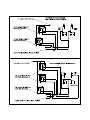
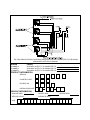
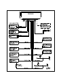
PRO-9600
Installation Guide
Remote Control Security System
With Pager/Satellite Control Interface
Installation Instructions
Kit Contents
PRO-9600 Control Module
4 Channel Code Learning Receiver
2 Three Button Anti-Code Grabbing Transmitters
Six Tone Multi-Tone Siren
Starter Inhibit Relay w/Socket
Main Wiring Harness
Auxiliary Wiring Harness
Plug In Valet
Plug In 2/Pin Door Lock Harness
Plug In LED
2 Pin Accessory VSS Harness
4 Pin Shock Sensor Harness
Plug In Two Stage Shock Sensor
Pin Switch Hardware Bag
Installation Guide
Owners Guide
Prestige Platinum Warranty
Consumer Activation Form
Window Warning Decals
The PRO-9600 is a full featured security system with on board paging technology that provides the consumer a direct link
to their vehicle from anywhere in the world. This patent pending technology allows the user to operate the vehicle from any
land or mobile telephone. The vehicle's owner can command the security system to arm or disarm, release the trunk, start
the vehicle, and in case of a carjacking, can put the PRO-9600 in a special carjack mode that will flash the lights, sound the
siren and prevent restarting of the vehicle.
NOTE: Many of the paging features available to the consumer are part of the alarm functions of the unit. Features such as
lock / unlock, arm, disarm, carjack, and reset will be available after installation with no special consideration on the part of
the installing technician. There are three additional auxiliary outputs accessible by paging the PRO-9600 that will require
some consideration. The Alarm's receiver channels 2, 3, and 4, are the same as paging auxiliary functions 1, 2, and 3.
These outputs, when connected to the vehicle, MUST BE NOTED on the Owners Guide, Rear Page Of This Manual and on
the Paging Registration Guide. Additionally, access from the RF transmitter may provide a latched output from these
channels however access from the paging network will only provide a 800 ms pulsed output. Please note this as it may
effect the options that you connect to these output wires. Each wire is referenced individually later in this manual.
MOUNTING THE COMPONENTS:
CONTROL MODULE:
Select a mounting location inside the passenger compartment up and behind the dashboard. The mounting location
selected must consider routing of the antenna to allow it to be fully extended, away from metal which may shield it, and as
high as possible to insure the best RF reception and operating range. Additional consideration should be made to keep the
control module away from on-board computers. These devices have local oscillators which may produce RF and inhibit or
limit reception.
Be certain that the chosen location will not interfere with proper operation of the vehicle. Avoid mounting the module to or
routing the wiring around the steering shaft/column, as the module's wiring may wrap around or block the steering wheel
preventing proper control of the vehicle. Secure the module in the chosen location using cable ties or screws as necessary.
Do Not Mount The Module In The Engine Compartment, it is not waterproof.
SIREN:
Select a location in the engine compartment that is not accessible from below the vehicle. The selected location must be
clear of hot or moving parts within the engine compartment. The siren must be pointed downward to prevent water retention
and the flared end must be pointed away and out of the engine compartment for maximum sound distribution. Before
securing the siren, check behind your chosen location to assure that the mounting screws will not penetrate any factory
wiring or fluid lines. Secure the siren mounting bracket using #8 self taping screws or, by first using the mounting bracket as
a template, scribe or mark the three bracket mounting holes. Drill the three marked holes using a 1/8" drill bit, then mount
the siren using #8 sheet metal screws.
HOOD AND TRUNK PIN SWITCHES:
The pin switches included in this package are intended for protecting the hood and trunk areas of the vehicle. In all cases,
the switch must be mounted to a grounded metal surface. When the pin switch is activated, (hood/trunk open), it will supply
a ground to the input wire activating the alarm. Mount the switches under the hood and in the trunk compartment in
locations away from water drain paths. If necessary, the included brackets may be used to move the switch away from rain
gutters or allow mounting to the firewall behind the hood seal. In both cases the switch must be set up to allow the hood or
trunk to depress the switch at least 1/4 inch when the hood or trunk is closed and fully extended when the hood or trunk is
opened. For direct mounting, a 1/4 inch hole must be drilled. Carefully check behind the chosen location to insure the drill
will not penetrate any existing factory wiring or fluid lines. Drill a 1/4" hole in the desired location and thread the pin switch
into it using a 7/16" nut driver or deep well socket. If using the mounting bracket, first secure the bracket to the desired
location and secure the pin switch in the pre-threaded mounting bracket hole.
DASH MOUNTED L.E.D:
The small red LED included in the kit will serve as a visual indicator of the alarm's status and provide a visual deterrent to
a potential thief. The LED also provides important feed back information during the transmitter and feature program modes.
The LED should be installed in the dash in an area highly visible so that it may be seen from the driver's seat as well as from
outside the vehicle. Inspect behind the chosen location to insure that the drill will not penetrate any existing factory wiring
or fluid lines. Carefully drill a 1/4" hole in the desired location and pass the connector end of the LED through the hole and
toward the control module. Press the LED firmly into place until it is fully seated in the mounting hole.
2
VALET/PROGRAM SWITCH:
Select a mounting location that is easily accessible to the operator of the vehicle. The switch can be mounted to the lower
dash panel in the driver's area. Inspect behind the chosen location to insure that adequate clearance is allowed for the
body of the switch, as well that the drill will not penetrate any existing factory wiring or fluid lines. Drill a 1/4" hole in the
desired location and mount the switch by passing it through the panel from the underside. Secure the switch using the nut,
star washer, and on/off face plate. It is suggested that the switch be oriented to allow the on position to be up toward the
driver and the off position to be down or away from the driver. Route the switches's connector toward the control module.
SHOCK SENSOR:
Select a centrally located, solid mounting surface for the shock sensor that will allow consistent operation from all areas of
the vehicle. The selected location must be within 18" of the control module to allow routing and connecting of the 4 pin
harness. Secure the shock sensor to the chosen location using two #8 self taping sheet metal screws. The sensor can
also be secured to an existing dash brace using cable tie straps. Whichever mounting method is used, be sure to allow
access to the sensitivity adjustment potentiometer for use later in the installation.
STARTER INHIBIT RELAY:
Select a mounting location within 12" of the ignition switches low current start solenoid wire. Secure the relay to an existing
harness in the chosen location using a cable tie around the relay's wiring harness. Caution! Do not wire tie the metal
bracket to an existing wiring harness as vibration may cause chaffing and shorting damaging the factory wiring. If an
existing harness is not available then secure the relay's metal mounting tab to an under dash metal brace with a #8 self
taping sheet metal screw. Wire the relay as per the diagram found later in this manual.
NOTE: Before connecting the module, pre-select all the wires in the vehicle. First, using a digital VOM, test all the wires
you intend to connect to in the vehicle. Disconnect the vehicle battery and complete all wiring to the vehicle before
connecting the control module to the harness connectors. This will prevent the pager from activating during the installation. Once all wiring is complete and the module is connected, disarm the unit immediately before proceeding with the
testing of the unit.
WIRING THE CONTROL MODULE:
8 Pin Main Wiring Harness
Red w/White Trace: + 12 volts Battery Source
Connect this wire to a constant + 12 VDC source found at the vehicles ignition switch using the 5 Amp fuse and holder
provided.
Orange Wire: Ground When Armed Output
This wire provides a 300 mA ground output when the alarm circuit is armed to control the starter inhibit relay. Connect the
Orange wire to terminal #86 (orange wire) of the previously installed starter interrupt relay. Connect terminal #85 (red wire)
of the relay to an ignition wire in the vehicle that is live when the ignition switch is turned to the on and start positions and
off when the key is off. Locate and cut the low current start solenoid wire found at the vehicles ignition switch harness. This
wire will have + 12 volts when the ignition key is moved to the start (crank) position and will have 0 volts in all other key
positions. Connect one side of the cut wire to terminal #87a ( Black wire) of the relay. Connect the other side of the cut wire
to terminal #30 (White/Black wire) of the relay.
Green w/ White trace Wire: Entry Illumination Ground Output
This wire provides a 30 second ground output (300 mA Max.) whenever the remote is used to disarm the alarm or to unlock
the doors and provides a continuous pulsed output whenever the alarm is triggered. This wire should be connected to an
external relay and wired to the vehicles interior entry lighting whenever the optional Interior Illumination circuit is desired.
Dark Blue Wire: Delayed 300mA Pulsed Channel 2 Output
The Dark Blue channel 2 output wire supplies a 300mA ground pulsed output whenever channel two of the receiver is
accessed. Pressing the pre-programmed transmitter button for three seconds will access channel two. Channel 2 is also
considered auxiliary output 1 available by satellite paging to the vehicle. Whether accessing this output form the key chain
transmitter or via the satellite paging network, the Dark Blue wire will provide a 800ms pulsed ground output. This is a low
current output and must be connected to a relay to supply power to the trunk release or the circuit you wish to control.
Connect the Dark Blue wire to terminal # 86 of a VF45F11 P&B relay or equivalent. Connect terminal # 85 of the relay to
a fused + 12 volt battery source. Connect the common, normally open, and normally closed contacts of the relay to
perform the selected function of channel 2.
3
White w/ Black Trace Wire: Positive (+) Siren Output
This is the positive siren feed wire. Route this wire through a grommet in the firewall to the siren location. Connect the White
w/ Black Trace wire to the Red wire of the Siren. Secure the Black wire of the Siren to a known chassis ground or solid clean
metal surface.
Black Wire: Chassis Ground Source
Connect the Black wire to a known vehicle ground source or to a solid clean metal part of the chassis. Be certain to remove any
paint or grease and secure this wire with a self taping screw and ring terminal.
2 White Wires: Low Current Directional Light Flash Output Wires
The PRO-9600 provides two different and distinguishable light flash patterns. During normal arming and disarming, a standard
alarm flash pattern is observed. When the unit is placed in a theft mode, from the paging network, a special light flash pattern,
(S.O.S.) is observed. This highly recognizable and very different flash pattern is necessary to distinguish a vehicle theft from a
vehicle break-in.
You must consider that the parking lights may be in the on position if the vehicle is carjacked or stolen, In this application
special consideration for wiring of the light flash circuit must be made. Audiovox advises that the directional element of the
bulbs be used in all cases to insure that this light flash pattern will be operational in all situations.
The two White wires provide, ( 300mA) low current pulsed ground outputs to control the light flash patterns. In all cases relays
must be used.
Three of the most common directional circuits available in today's vehicles are:
1. Four Independent Bulbs, LF,LR,RF,RR.
2. Left Front And Rear Common / Right Front And Rear Common
3. Rear Common Front Independent.
Wiring for these circuits are shown later in this manual.
10 Pin Mini Wiring Harness:
Light Blue Wire: Low Current Latching Output / Channel 4
The Light Blue, channel 4 output wire latches to ground via an independent RF channel from the keychain transmitter. Channel
4 is also considered the Auxiliary 3 output available by satellite paging to the vehicle. When operating this channel from the
paging network, this output will be a pulsed 800ms output. Consider this when connecting to an accessory in the vehicle. Be
certain to list the function of this output in the Owners Manual, Owners Paging Manual, and on the rear page of this manual.
This wire provides an immediate ground signal, and remains grounded as long as the transmitter button(s) is held. This is a low
current (300mA) output and in all cases will be used to drive an external relay coil. To use the Light Blue wire, connect it to
terminal # 86 of a P&BVF45F11 or equivalent relay. Connect terminal # 85 of the relay to a fused + 12 volt battery source.
Connect terminal # 30 of the relay to ground or a fused + 12 volt battery source, dependent upon the device in the vehicle you
wish to control. Connect terminal # 87 to the vehicle's switched device's control wire.
Dark Green w/ Black Trace Wire: low Current Latching Output / Channel 3
The Dark Green w/ Black trace, channel 3 output wire latches to ground via an independent RF channel from the keychain
transmitter. Channel 3 is also considered the Auxiliary 2 output available by satellite paging to the vehicle. When operating this
channel from the paging network, this output will be a pulsed 800ms output. Consider this when connecting to an accessory in
the vehicle. Be certain to list the function of this output in the Owners Manual, Owners Paging Manual, and on the rear page of
this manual.
This wire provides an immediate ground signal, and remains grounded as long as the transmitter button(s) is held. This is a low
current (300mA) output and in all cases will be used to drive an external relay coil. To use the Dark Green w/ Black Trace wire,
connect it to terminal # 86 of a P&BVF45F11 or equivalent relay. Connect terminal # 85 of the relay to a fused + 12 volt battery
source. Connect terminal # 30 of the relay to ground or a fused + 12 volt source, dependent upon the device in the vehicle you
wish to control. Connect terminal # 87 to the vehicle's switched device's control wire.
Black w/ White Trace Wire: 300mA Ground Horn Output
The Black w/ White Trace wire will provide a pulsed ground output which can be used to sound the vehicle's horn. This is a low
current (300mA) output and must be connected to a relay for proper operation. Most vehicles have a horn relay connected to
the horn switch. If the existing relay requires less than 300 mA then direct connection to the horn wire is possible. If the vehicle
horn does not switch a existing low current relay or if the horn circuit is + 12 volts switched, you must connect the Black w/ White
Trace wire to a external relay coil. When connecting to an external relay, connect the Black w/ White Trace wire to terminal #
86 of a P&B VF45F11 or equivalent relay. Connect terminal # 85 to a fused +12 volt battery source. Arrange terminals # 30 &
# 87 to switch ground or + 12 volts as necessary for the horn circuit you are connecting to.
Orange w/ White Trace Wire: Low Current Ground When Disarmed Output
The Orange w/ White Trace wire provides a ground output when the security system is disarmed. This low current (300mA),
output may be used to control a normally open Starter Inhibit Circuit where desired. To use the Orange w/ White Trace wire,
Connect the Orange w/ White Trace wire to terminal # 86 of a P&BVF45F11 or equivalent relay. Connect terminal # 85 of the
relay to an ignition wire in the vehicle that has + 12 volts when the ignition key is in the on and start positions and has 0 volts in
the off and accessory positions. Locate and cut the low current start solenoid wire found at the vehicles ignition switch harness.
Connect terminal # 30 of the relay to the ignition switch side of the cut wire. Connect terminal # 87 of the relay to the starter side
of the cut wire.
NOTE: This normally open starter cut relay arrangement will prevent the vehicle from starting if the control module or wiring to
the control module is disconnected or removed. Audiovox does not recommend the use of this circuit to interrupt anything but
the starting circuit of the vehicle.
4
Dark Green Wire: (-) Instant Trigger Zone 2
The Dark Green wire is the instant on ground trigger input wire. This wire must be connected to the hood and trunk pin
switches previously installed. Note: This wire will be shunted when remote control channel 2 is accessed, (trunk release).
This wire will remain shunted all the while there is ground present, and for 5 seconds after the ground is removed. This allows
the operator to open the trunk via the remote transmitter without having to first disarm the alarm system.
Brown Wire: (-) Negative Door Trigger Input
If the vehicle's door courtesy light switches ground when the door is opened, (Most GMs and Imports), you must connect this
wire to the negative output from one of the vehicle's door pin switches. In most cases the Brown wire will need to be connected
to only one door switch no matter how many doors the vehicle has as most door lighting circuits are wired in parallel.
Purple Wire: (+) Positive Door Trigger Input
If the vehicle's door courtesy light switches + 12 volts when the door is opened, (Most Fords and some Imports), you must
connect this wire to the positive output from one of the vehicle's door pin switches. In most cases, the Purple wire will need to
be connected to only one door switch no matter how many doors the vehicle has as most door lighting circuits are wired in
parallel.
Yellow Wire: (+) 12 Volts Ignition Switch Input
Connect this wire to a source in the vehicle that is live when the ignition switch is in the on and start positions, and has 0 volts
in all other switch positions.
White w/ Blue Trace Wire: Low Current (-) Ground Headlight Output
The White w/ Blue Trace wire is provided to operate the optional headlamp illumination feature of the system. This is a low
current (300mA) output and must be connected to an external relay to control the high current switching circuit of the vehicle's
headlamps. To use this option, Connect the White /w Blue Trace wire to terminal # 86 of a P&B VF45F11 relay or equivalent.
Connect Terminals #85 and # 30 to a fused + 12 Volts source with a current capability equal to or in excess of the factory
headlamp fuse. Connect terminal # 87 of the relay to the switched + 12 volt wire feeding the vehicle's headlamp circuit.
NOTE: For ground switched headlamp circuits, Connect the White /w Blue Trace wire to terminal # 86 of a P&B VF45F11
relay or equivalent. Connect Terminal #85 to a fused + 12 Volts source. Connect terminal # 30 to a clean chassis ground.
Connect terminal # 87 to the ground switched headlamp control wire in the vehicle.
Light Green Wire: (-) Instant Trigger Zone 1
This is a instant on ground trigger input intended for the connection of optional triggering devices. The ground trigger output
wire of motion detectors, microwave detectors, or glass break detectors, can be connected to this Light Green trigger input
wire.
2 Pin Valet/Program Switch: (Blue Connector)
The Black & Grey twin lead wires loaded in the two pin blue connector are the ground supply and program/valet input of the
PRO-9600. When the Grey wire is grounded, under certain conditions, the unit will enter the valet mode. When the Grey wire
is sequentially grounded under other conditions, the unit will enter the various program modes. Route the twin lead Black and
Grey wires from the valet/Program switch to the PRO-9600 and plug the two pin connector into the mating blue connector shell
of the control module. Refer to the remote programming, feature programming and function programming shown later in this
installation guide for operation of the valet/program switch.
2 Pin Door Lock/Unlock Harness: (White Connector)
The Red & Green Door Lock/Unlock output wires provide either a pulsed ground or pulsed + 12 volts to control the vehicle door
lock / unlock circuits. The output of these wires has a maximum switching capability of 300mA. Many vehicles today have
factory door lock relays which can be connected directly to these outputs, however always confirm that the factory relays in
your particular vehicle do not exceed the rated 300mA output of the unit's door lock/unlock circuit. Plug the two pin connector
of the door lock/unlock harness into the mating connector shell of the control module. Determine the door lock circuit of the
vehicle you are working on and wire according to the diagrams shown.
3 Wire Ground Switched Door Lock Circuits:
In this application, the Red wire of the two pin harness provides a ground pulse during the arming sequence, or pulsed ground
lock output. Connect the Red wire to the low current ground signal from the factory door lock switch to the factory door lock
relay.
The Green wire of the two pin harness provides a ground pulse during the disarming sequence, or pulsed ground unlock
output. Connect the Green wire to the low current ground signal from the factory door unlock switch to the factory door unlock
relay.
3 Wire Positive Switched Door Locks:
In this application, the Red wire of the two pin harness provides a + 12 volt pulse during the disarming sequence, or pulsed
12 volt unlock output. Connect the Red wire to the low current 12 volt signal from the factory door unlock switch to the factory
door unlock relay.
The Green wire of the two pin harness provides a + 12 volt pulse during the arming sequence, or pulsed 12 volts lock output.
Connect the Green wire to the low current 12 volt signal from the factory door lock switch to the factory door lock relay.
Note: For connection to Four Wire Polarity Reversal, 5 Wire Alternating 12 Volts, And All Other Door Lock Circuits the
Audiovox AS-9159 Door Lock Interface, (or equivalent 30 A automotive Relay must be used. Refer to the Audiovox Door Lock
Wiring Supplement for proper wiring of these circuits.
5
2 Pin Auxiliary Harness: (Red Connector)
The two pin auxiliary connector is used to control vehicle shut down from a paging theft command. See supplement for wiring
information.
Connecting The Dash Mounted LED:
Plug the two pin white connector from the previously installed LED into the mating two pin white female connector shell of the
control module.
Connecting The PRO-9600 Module:
Re-connect the vehicle's battery then plug the main and mini connectors into the mating connector shells of the control module.
Immediately disarm the system with the hand-held transmitter to prevent the pager board from activating.
Programming The PRO-9600:
The transmitter programming is pre-set from the factory so that Button 1 controls Arm/Disarm, Button 2 controls Channel 2
output, Button 3 controls Channel 3 output, Button 2&3 controls Channel 4. If the consumer wishes a different configuration,
see separate transmitter programming guide packaged with this kit.
Keep in mind that Alarm Channel 2 = Pager Auxiliary output 1, Alarm Channel 3 = Pager Auxiliary output 2, and Alarm Channel
4 = Pager Auxiliary output 3.
The alarm features are pre-programmed at the factory for the most common configuration. If you wish to change any of these
settings, refer to the Alarm Selectable Feature programming later in this manual.
Testing The PRO-9600:
Testing The Unit's Outputs Via The On Board Test Switch:
IMPORTANT! Do not fax the activation sheet until the system has been thoroughly tested, and all functions that have been
connected are operating properly.
Note: Make sure that you have at least 1 window open and the keys out of the vehicle before operating the test switch or the
paging test sequence.
1. Slide open the access door of the module case and locate the push button test switch.
2. Using the rubber end of a pencil eraser, depress the push button one time.
The PRO-9600 will simulate the following events sequencing through each command with a 5 second interval between each
sequence:
A. Auxiliary Output 1
C. Auxiliary Output 3
E. Arm Alarm
G. Carjack
B. Auxiliary Output 2
D. Door Unlock
F. Disarm Alarm
H. Reset All
After the push button test is complete and you've confirmed the proper operation of all functions, proceed with the Radio
Frequency Test.
3. From a touch tone phone, dial the appropriate test phone number and request a test signal for the serial number of the unit
being tested.
4. The signal will be received at the vehicle and the following sequence of events will be observed. There will be a 5 second
interval between each sequence:
A. Auxiliary Output 1
C. Auxiliary Output 3
E. Arm Alarm
G. Carjack
B. Auxiliary Output 2
D. Door Unlock
F. Disarm Alarm
H. Reset All
After confirming that all options connected to the PRO-9600 are operating properly, complete the activation form supplied
with the unit. Make sure all selectable auxiliary options are clearly identified on the application sheet, owners manual and on
the last page of this manual.
NOTE: After verifying that the RF test was successful, you will need to specifically test the theft / hijack command for two
functions.
1. During this portion of the test, the vehicle must be running. From a touch tone phone, dial the appropriate test phone number
and request a theft signal for the serial number of the unit being tested. Once the signal is received, turn the engine off.
Attempt to restart the vehicle. If the engine starts, check your connections to the starter inhibit relay. After verifying that the
engine will not start after receiving the RF theft command, reset the system by calling the test telephone number and request
a reset command for the unit being tested.
2. During this portion of the test, be sure that the vehicle is started and moving. You must confirm that the vehicle will not shut
down until 5 seconds after the vehicle comes to a complete stop. This will confirm that the VSS connection and ignition
interrupt circuits are operating properly. Failure to complete this portion of the test could result injury to the occupant(s) of
the vehicle. This test may require the use of an assistant to place the call if you do not have a cellular phone available.
While driving above 3 MPH, call the test telephone number and request a theft/hijack signal be sent. Once the signal has
been received, wait 10 seconds, then allow the vehicle to come to a complete stop. After 5 seconds, the vehicle should stall.
If the vehicle continues to run, you will need to recheck your connections to the ignition control relay. First call the test center
and request a reset, confirm your connections to the VSS circuit and the ignition control relay, then repeat the above test until
the vehicle stalls as described. Upon completion call the test center and request a reset.
6
Connecting And Adjusting The Shock Sensor:
Route the 4 pin cable from the previously installed shock sensor to the control module. Plug it into the mating 4 pin white
connector shell located along side the 8 pin main harness connector of the control unit.
Pre- adjust the previously installed Shock Sensor by first accessing the potentiometer setting screw and carefully turn this
adjustment all the way counterclockwise. Now Turn the adjuster clockwise to the first notch on the module case.
CAUTION! Use caution when striking the vehicle and around the glass panels. Impact tolerances of vehicle glass differs from
vehicle to vehicle. This test can also be made by striking the vehicle bumpers providing you consider the amount of force
required to break a window.
Exit the vehicle, close all doors, hood and trunk and arm the alarm system.
Firmly strike the windshield pillar with the open palm of your hand. If the alarm system triggers, disarm then re-arm the
system and make the same test on the rear window support. If the system triggers, no further adjustment is necessary.
If in the above test the sensor did not trigger the alarm system, carefully move the adjustment potentiometer in a clockwise
direction and re-test in the same manner until the desired results are achieved.
Confirm the Alarm's operation by arming the alarm, testing an entry point then disarming. Follow this sequence until all
protected areas have been tested. While testing, observe the operation of the parking lights for proper operation, confirm that
the siren chirp patterns for arm, disarm, disarm after intrusion and arm while a door is open are operating properly. If
headlight illumination is used, check to insure proper operation.
ALARM SELECTABLE FEATURES
RF Programmable Features:
Feature Selection
1 Chirp
2 Chirp
Default
First
1 Second Door Locks
3.5 Second Door Lock
1 Second
Second
Auto Lock On
Auto Lock Off
Auto Lock Off
Third
Auto Unlock On
Auto Unlock Off
Auto Unlock Off
Fourth
Headlight Output On
Headlight Output Off
Headlights On
Fifth
Passive Door Locks
Active Door Locks
Active Door Locks
Sixth
Passive Arming
Active Arming
Passive Arming
To Program The Alarm's Selectable Features:
Action
Turn the ignition switch on
Flip the valet/program switch on then off 3 times
Within 3 seconds, turn the ignition switch off,
then on
Press transmitter button 1 to change.
Or
Flip valet/program switch on then off
Second Press transmitter button 1 to change.
Or
Flip valet/program switch on then off
Press transmitter button 1 to change.
Third
Or
Flip valet/program switch on then off
Fourth Press transmitter button 1 to change.
Or
Flip valet/program switch on then off
Press transmitter button 1 to change.
Fifh
Or
Flip valet/program switch on then off
Press transmitter button 1 to change.
Sixth
Or
Flip valet/program switch on then off
Or
Turn ignition switch off.
First
System Response
LED Flash Pattern
No Response
1 Chirp-LED 1 Flash
Short Chirp, then Long Chirp
1 Chirp = 1 second Locks
2 Chirps = 3.5 second Locks
1 Flash Pause etc.
2 Chirps = auto locks off
1 Chirp = auto locks on
2 Falsh Pause etc.
2 Chirps = auto unlock off
1 Chirp = auto unlock on
3 Flash Pause etc.
1 Chirps = headlight o/p On
2 Chirp = headlight o/p Off
4 Flash Pause etc.
2 Chirps = Active Locks
1 Chirp = Passive Locks
5 Flash Pause etc.
1 Chirp = passive arming
2 Chirps = active arming
6 Flash Pause ect.
Exit Program Mode
Exit Program Mode
NOTE: Once you've entered the program mode DO NOT allow more than 15 seconds to pass between steps, or the programming mode will be terminated.
7
8
THE FOLLOWING OPTIONS HAVE BEEN INSTALLED AND ARE CONNECTED TO THE ALARM
AND PAGER OUTPUTS AS SHOWN
ALARM
PAGER
CHANNEL 2
CHANNEL 3
CHANNEL 4
AUXILIARY OUTPUT 1 IS CONNECTED TO
AUXILIARY OUTPUT 2 IS CONNECTED TO
AUXILIARY OUTPUT 3 IS CONNECTED TO
PRODUCT INFORMATION
SERIAL #
COUNTRY CODE
DLR/DIST ID#
INSTALLATION DATE
VEHICLE INFORMATION
VEHICLE YEAR
VEHICLE MFG.
VEHICLE COLOR
LICENSE PLATE#
VIN#
9
VEHICLE MOD.
10
PRO-9600
MODULE
PRO-9600
11
VSS WIRING SUPPLEMENT
The two pin auxiliary harness with the red connector shell provides a input signal to the control module from the vehicle's
Speed Sensor ( VSS), and provides a low current ground switched output to control a shut down relay.
The relay can be used to interrupt any circuit in the vehicle which will cause the vehicle's engine to stop running.
Typically the contacts of this relay can be used to interrupt the primary (+) feed wire of the ignition coil or the positive feed
wire controlling the electric fuel pump.
Whichever circuit you choose to interrupt, be certain that you fully test the operation of the shut down circuit as described
on page 6 of the installation manual.
TO INSTALL THE VSS SHUT DOWN CIRCUIT:
1. Locate the VSS signal wire found in the vehicle at the ECM or the signal generator.
2. Connect the Black wire of the two pin connector to the previously located VSS signal wire.
3. Connect the Red wire of the two pin connector to terminal #86 of a P&B VF45F11 or equivalent 12 volt automotive
relay.
4. Connect terminal # 85 of the relay to a + 12 volt ignition source. This wire will have + 12 volts with the ignition
switch turned to the on and start positions and will have 0 volts with the ignition switch in the off or accessory positions.
5. Connect the common contact (#30), and normally closed contact (87a) to the circuit you wish to interrupt as shown
below.
Red Wire Of 2
Pin VSS Harness
NOTE: Be certain to follow the test procedure as outlined on page 6 of the installation manual.
Form No. 128-5167
12