1
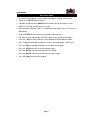
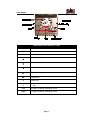
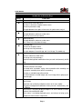
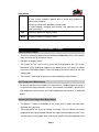
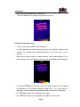
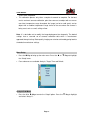
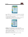
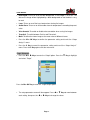
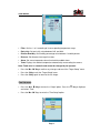
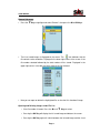
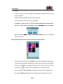
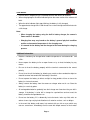
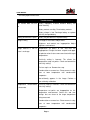
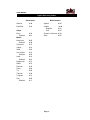
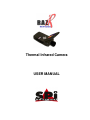
Thermal Infrared Camera
USER MANUAL
USER MANUAL
Sierra Pacific Innovations Corp
6620 S Tenaya Way, Bldg #100-110
Las Vegas, NV 89113 USA
(702) 369-3966
(702) 369-3977 Fax
www.imaging1.com
® SPI Corp
Products mentioned herein are not available for export from the USA.
Publication No: raz9959 M4 UM 008
Notices:
The RAZ-IR is an ISO9001:2000 certified instrument based upon its design,
manufacture, in-house repair support, warranty practices, and other criteria that are of
importance to those that will depend on the quality of this equipment.
Sierra Pacific Innovations, hereafter SPI, reserves the right to make
changes and improvements on any of the products described in this
manual without prior notice.
RAZ-IR thermal cameras comply with current European directives relating to
electromagnetic compatibility and safety. (EMC directive 89/336/EEC; Low voltage
directive 73/23/EEC)
Copyright
© SPI - All rights reserved worldwide. No SPI products may be reproduced in whole or in
part or transmitted, transcribed or translated into any language or converted into any
computer language in any form or by any means, electronic, magnetic, optical, manual
or otherwise, without the prior written permission of SPI. This manual cannot, in whole or
part, be copied, photocopied, reproduced, translated or otherwise converted to any
electronic medium or machine readable form without the prior written consent of SPI.
Page 2
USER MANUAL
Table of Contents
Introduction .................................................................................................................. 4
Precautions.................................................................................................................. 4
Maintenance ................................................................................................................ 5
Calibration and Repair Philosophy .............................................................................. 5
Technical Support ........................................................................................................ 6
Feedback to Us ........................................................................................................... 6
System overview ......................................................................................................... 6
Customer Benefits ....................................................................................................... 7
System Configuration .................................................................................................. 7
Technical Specifications .............................................................................................. 8
Camera Features......................................................................................................... 9
Quick Start Guide ...................................................................................................... 11
Control Keys Quick Reference Table ........................................................................12
Introduction to Selection Keys...................................................................................13
Using the Camera – In Detail ....................................................................................14
Battery Charging........................................................................................................35
Troubleshooting .........................................................................................................37
Emissivity...................................................................................................................38
Typical Emissivity Values...........................................................................................40
Page 3
USER MANUAL
Introduction
This publication provides the necessary information required to safely operate the
RAZ-IR thermal camera.
Compared to previous publications, this edition has been revised based upon recent
camera modifications, such as the extended temperature range improvements up to
℃,
250
the procedure for choosing and displaying temperatures in Celsius and
Fahrenheit, the background modification function and other improvements.
This equipment should only be used, maintained and serviced by properly trained
personnel, capable of carefully following the procedures and guidelines given in this User
Manual.
This User Manual and other operating instructions provided should be thoroughly read
and understood before proceeding with the operation of this equipment. Be sure to save
and retain all such operating instructions for other users and for your future reference.
Precautions
The following precautions must be adhered to at all times and must be considered in
addition to any advised precautions issued at the relevant worksite or work area in order
to protect the thermal camera from damage.
•
Do not direct the RAZ-IR thermal camera at very high intensity radiation sources
such as the sun, carbon dioxide lasers, arc welders, etc.
•
Always replace the lens cap when the unit is not in operation.
•
Never point the RAZ-IR thermal camera at high-temperature sources or objects
when powering the unit on.
•
Wait for 10 seconds or longer to restart the camera after turning it off.
•
Protect the RAZ-IR thermal camera from rough handling situations that may cause
physical damage to the camera’s external housing, lenses and internal
components.
•
The RAZ-IR thermal camera should only be operated when the ambient temperature
is between -10 and +50 degrees Celsius.
•
When the RAZ-IR thermal camera is not in use or is to be transported, ensure that the
unit and its accessories are properly stored in the protective carrying case.
Page 4
USER MANUAL
•
The RAZ-IR thermal camera incorporates precision optical equipment and
static-sensitive electronics which should be protected from shock and vibration at all
times.
•
Do not cover, impede or otherwise block the air ventilation ports on the RAZ-IR
thermal camera body.
•
Do not attempt to open the camera body as this action will void the manufacturer’s
warranty.
The RAZ-IR thermal camera is powered by a Lithium Ion (Li-Ion) rechargeable battery
pack. The following safety precautions must be adhered to at all times to ensure the safe
use of this equipment:
•
•
•
Do not disassemble or attempt to open these batteries under any circumstances.
Do not expose these batteries to fire or other high temperature sources.
Do not short circuit these batteries intentionally or inadvertently by allowing metal
objects to come into contact with the battery terminals.
•
•
Do protect the batteries from water and other sources of moisture.
The batteries should only be charged using the recommended and supplied charging
device.
Maintenance
To ensure that the RAZ-IR thermal camera is kept in good working condition and remains
fully operational, the following guidelines should be adhered to at all times:
Non-optical surfaces
The non-optical surfaces of the camera can be cleaned, when required, with a soft cloth
dampened with water and a mild detergent.
Optical surfaces
The optical surfaces of the camera lens should only be cleaned when visibly dirty. Care
should be taken to avoid touching the exposed lens surface because skin acid left behind
from fingerprints can be damaging to coatings and lens substrates. Use only a proprietary
lens cleaning tissue when necessary.
Calibration and Repair
To ensure the accuracy and reliability of the RAZ-IR thermal camera, it is highly
recommended that the instrument be calibrated annually.
Page 5
USER MANUAL
If your camera needs repair or servicing, contact SPI to arrange for the instrument to be
returned.
Caution
The RAZ-IR thermal camera does not incorporate any user serviceable parts. Never
attempt to disassemble or modify the camera. Opening the unit housing voids the
warranty.
Technical Support
Technical support for your RAZ-IR thermal camera system can be obtained by either
contacting the address / telephone number on the cover of this User Manual or by Email
to the following address: [email protected]
Feedback to Us
We have tested and verified the information in this manual to the best of our abilities. In
that we are committed to continuous development and progress, you might find features
of the product have been changed since the time of printing. Please let us know about
any error you find and your suggestions for improvements for future editions by either
contacting us at the address/telephone number on the cover of this User Manual or by
Email to the following address: [email protected]
System Overview
SPI’s RAZ-IR thermal camera leads another breakthrough in today’s Infrared Thermal
Imaging industry.
Emerging as the first mobile phone like IR camera in the world, the RAZ-IR thermal
camera is sized, configured and priced to open the door to many new uses of Thermal IR
Imaging. It provides a wide assortment of unique new features enabling professional
thermographers to work with efficiency and productivity greater than ever before: crisp
thermal and visual imaging, efficient voice annotation, fully onboard image processing,
large capacity in-field storage, fast image download via USB connectivity, low power
dissipation, long durability, and much more.
The RAZ-IR thermal camera is the only IR camera that offers all the possibilities of a high
range camera at an unanticipated affordable price, enabling high-performance thermal
Page 6
USER MANUAL
imaging where never possible before.
Options Available:
-Direct live real-time Camera to PC USB interface module available for digital snapshot
or video image capture.
-Telephoto Afocal Germanium Long Range NFOV optics lens.
Customer Benefits
As an ultra-portable IR camera with big-camera power, the RAZ-IR thermal camera
provides outstanding thermal imaging of the highest quality and presents a range of
benefits to the customer such as:
•
•
•
•
•
•
•
•
•
Ultra-compact, lightweight & fully integrated
Ease of operation and light-weight design
Precision non-contact temperature measurement
Ultra large capacity in-field image storage
Plug-and-play connectivity
Low power dissipation and long durability
Robust post-processing software
Affordable price & high reliability
License free & rapid delivery
System Configuration
Check that the following items have been correctly supplied:
•
•
•
•
•
•
•
•
•
•
•
•
RAZ-IR Thermal Camera
13mm IR lens
Rechargeable Li-ion batteries
Battery charger
USB extension cable
Earphone
USB driver
Post-analysis SPI Analysis Software®
User manual
Leather Case
Soft carry bag
Packing case
Page 7
USER MANUAL
Technical Specifications
Image Performance
Thermal:
Detector type:
Spectral Range:
Field of View/ Focus:
Thermal Sensitivity:
Image display:
Electronic Zoom:
Microbolometer UFPA (160 x 120 pixels, 35µm)
8-14µm
25° x 19°/12.6mm
℃
≤120mk @30
256 level, 8 palettes (Rainbow, iron, B&W, etc)
2×
Visual:
Built-in Digital Video:
Image Presentation:
External Display:
Measurement:
Temperature Range:
Accuracy:
Measurement Modes:
CMOS Sensor, 640 x 480 pixels, 224 colors
2.2” TFT & 1.2” CSTN high resolution color LCD
℃
℃
-20 -+250
±2oC or ± 2%of reading
Auto hot-spot trace, 4 moveable spots,
4 moveable areas (min, max, mean), sound
Measurement Correction:
,
alarm isotherm
Emissivity variable from 0.01 to 0.99 (in 0.01
increments), automatic correction based on
optics transmission, ambient temperature,
distance, relative humidity, etc.
Image Storage:
Type:
File Format:
Built-in Flash memory (8G bit capacity)
IRI (An individual file consists of Infrared image,
visual image and voice notation saved, if any)
Voice Annotation:
System Status Indication:
LCD Display:
Sound Alarm:
Laser Locator:
Classification:
Battery System:
Type:
Operating time:
Charging System:
30 seconds per image
status of battery, indication of power
Automatic alarm for power shortage
Semiconductor A1GaInP Diode Laser
Li-ion battery, rechargeable, field replaceable
Over 2 hours continuous operation
In camera via USB interface from AC adapter or
Page 8
USER MANUAL
using external battery charger
2W
Power consumption:
Environmental Specification:
Operating Temperature:
℃-+50℃
-20℃-+60℃
-10
Storage Temperature:
Humidity:
Operating and storing 10% to 95%, noncondensing
IP54
Operational: 25g, IEC 68-2-29
Operational: 2g, IEC 68-2-6
Encapsulation:
Shock:
Vibration:
Interfaces:
USB1.1:
Image (thermal & visual), measurement, and
voice transfer to PC
Physical Characteristics:
120mm x 60mm x 30mm (Standard Model)
0.265Kg (including battery)
Black
Size:
Weight:
Color:
Camera Features
Image
• Images may be displayed on the camera’s LCD screen in black & white and color
(256 levels).
• Live images being viewed can be frozen on the camera and captured on the flash
memory device installed in the camera.
• Live images being viewed can be enlarged using the electronic 2× digital zoom
(provided that the menu is not being displayed on the screen).
• Saved images can be transferred to a computer via the USB extension cable.
Freeze and Save
• Live images can be captured on the camera display screen.
• Captured images can be saved using the flash memory feature of the camera.
• Up to 600 images can be saved and up to 30-seconds of voice annotation can be
saved for each image.
• Voice annotation, visual image and thermal image can be captured using the flash
memory feature simultaneously.
• Frozen or saved images can be further processed right in the camera.
Page 9
USER MANUAL
Replay
• Saved images can be replayed on the camera or externally on your computer.
• Voice annotation and saved images can be simultaneously replayed on the camera
and on a computer monitor.
• Replayed images on the camera can also be processed right in the camera.
• Saved images can be transferred to a computer via the USB extension cable for post
processing using the analysis software.
Temperature Measurement
• Automatic trace for hot spot on the screen;
• Automatic indication of temperature for the center of the screen;
• Measurement of any spot within the screen;
• Simultaneous measurement of four user selectable spots within the image showing
max, min or mean temperature of these areas;
• Measurement of any lines showing temperature profiles;
• Isotherm measurement which displays all spots from the image within a defined
temperature range in the same color;
• Automatic non-uniformity calibration ensures temperature measurements which are stable
and accurate.
Menu Setup
• Allows the user to set up temperature measurement parameters and the camera
functions;
• Provides automatic measurement correction based on user input for emissivity,
distance, relative humidity, atmospheric transmission and external optics.
Page 10
USER MANUAL
Quick Start Guide
• Be certain that the battery is fully charged and properly installed in the camera;
• Power on the RAZ-IR thermal camera;
• Flip open the top half of the RAZ-IR thermal camera to view the display screen;
• Wait for 15 seconds and remove the lens cap;
• Non-uniformity Correction (NUC) is performed automatically when the camera is
powered on;
• Point the RAZ-IR thermal camera at any object to be analyzed;
• Use the lens focal ring and adjust the focus to get a clear image on the display;
• Press the
• Press
• Key for three seconds to switch between Auto and Manual modes;
• Key and then adjust brightness, contrast and color palette, if necessary;
◄ Key to display and view a visual image of the target;
Press the ◄ Key to return to the live thermal image;
• Press the
•
• Press the OK Key to freeze and capture the live image;
• Press the OK Key again to save and store the frozen image;
• Press the C Key to resume live imaging.
Page 11
USER MANUAL
Control Keys Quick Reference Table
ABBREVIATION
DESCRIPTION
On/Off
Power Key
M
Menu Key
▲
▼
◄
►
Up Arrow Key
Down Arrow Key
Left Arrow Key
Right Arrow Key
OK
Confirm Key
C
Cancel Key
•
• Key
Left
To lighten or darken the display screen
Right
To lighten or darken the display screen
Page 12
USER MANUAL
Introduction to Selection Keys
KEYS
On/ Off
M
▲
▼
◄
►
FUNCTION
Power on/off
To enter menus and sub-menus
To select a sub-menu or option under a menu
To confirm parameter setup
To toggle between four spots or four areas for spot or area analysis
Up Arrow Key
To toggle between sub-menus under menu
To turn on or turn off laser locator
Down Arrow Key
To toggle between sub-menus under menu
To 2× zoom in the live thermal image
Left Arrow Key
To return to the parent menu
To change value of parameters
To switch between infrared image and visual image, Pro model only
Right Arrow Key
To enter sub-menus under menu
To change value of parameters
To perform background modification when pressed simultaneously with C
Key
OK
To select one sub-menu or option under menu
To freeze and store live image
To record voice annotation, replay voice annotation after recording and
bring up the recording menu when re-recording
To replay a selected image after preview
To switch between infrared image and visual image when replaying the
stored images
C
To cancel one sub-menu or option under menu
To exit menu
To perform non-uniformity calibration (when not in menu mode)
To perform background modification when pressed simultaneously with
the ► Key
When menu is not being displayed, depress for three seconds to switch
between Auto and Manual mode
When menu is not being displayed, press and release to bring up the
temperature measurement setup menu
•
Page 13
USER MANUAL
To stop recording a voice annotation
To save a voice annotation together with an image after recording or
replaying the recording
To delete an image when previewing saved images
To switch between “changing area location” and “adjusting area size”
under area analysis
Left
To lighten or darken the display screen
Right
To lighten or darken the display screen
Using the Camera – In Detail
Powering on the camera
• Turn on the camera by depressing and holding the Power Key until the two indicator
lights on the top half of the camera are on;
• Flip open the display screen;
• The “Power on Test” results of the system will be displayed on the LCD screen.
Meanwhile, a blue loading bar appears at the bottom of the LCD screen to indicate
the camera initialization progress. After fully loading, the camera will cycle into auto
startup mode;
• The camera is now ready for dynamic real time temperature measurement.
Basic Temperature Measurement
For basic temperature measurement, first ensure that a suitable temperature range is
set and that the image selected is in focus. Two methods are available, “dynamic real
time temperature measurement” and “static temperature measurement” as explained
below.
Dynamic Real Time Temperature Measurement
• The palette is shown at the bottom of the screen with its upper and lower limits
displayed at the two ends.
• Two temperatures are shown just above the palette. The first indicates the lowest
temperature limit and the second indicates the highest scene temperature limit. There
are two arrows on the palette which indicate the specific color corresponding to the
Page 14
USER MANUAL
lowest and highest temperatures, respectively.
• The center temperature is displayed at the top of the screen.
Setting the temperature range
• There are two modes available - Auto and Manual.
• To switch between one mode and the other, press and hold the
• Key for three
seconds. The selected mode is displayed briefly on the screen after the key is
released.
• Within Auto or Manual mode, the setup parameters menu can be displayed. This is
achieved by pressing the
• Key. The item which can be modified will be highlighted.
• Press ▲ and ▼ Keys to change values when the upper or lower limits of the palette
are highlighted, to shift between different palettes from 1 to 8 when palette is
highlighted, and to shift between Auto Mode and Manual Mode when highlighted.
• Press ► Key to display and shift between each option.
• Press ◄ Key to display and shift between each option in reverse order.
Page 15
USER MANUAL
• In Auto Mode, if you highlight the upper or lower limits of the palette and press
and
▼
▲
Keys to change its value, the mode will change to Manual Mode
automatically.
• Press either OK or C Keys to confirm the selection.
Static Temperature Measurement
• Hold the camera as steady as possible with the image in focus. Press the OK Key
to freeze the live image. The word “Frozen” will appear on the screen to indicate the
current status of the image.
• Press any Key except OK to cancel this operation, if necessary.
• Press the ▲,
▼, ◄ or ► Keys to position the center cursor.
• The value displayed at the top of the screen shows the temperature of the moving
cursor.
• Imaging performance varies based upon temperature ranges and palettes selected.
• Setting the temperature range is the same as explained in the dynamic real time
temperature measurement section above.
Main Menu Introduction
• This section covers the main menu options and their sub-menus. The main menu is
brought up on the screen by pressing the M Key.
• The menus can be navigated by pressing the▲,
▼, ◄ or ►
Keys and the
highlighted option is confirmed by pressing the M or OK Keys.
• Setup Analysis: Allows for the camera functions to be set.
• Setup Target: Allows for temperature measurement parameters to be set.
• Setup Time: Allows for the date and time to be set.
• Setup Default: Restore the factory configured value of all the parameters.
• File Browse: To preview and open saved images.
• File Delete All: To delete all of the saved images.
Page 16
USER MANUAL
• Analysis Spot: Allows up to four spot measurements to take place on saved or
frozen images.
• Analysis Line: Allows line profile measurement to take place on saved or frozen
images
• Analysis Area: Allows up to four rectangular area measurements to take place on
saved or frozen images, displaying maximum, minimum and mean temperatures.
• Analysis Isotherm: Allows for an isotherm to be placed on live, saved or frozen
images.
• To exit the menu system at any time and return to the image press C Key.
Switching Between Infrared Image and Visual Image
• You can toggle between the infrared image and visual image
• When there is no menu on display screen, press the
◄
Key to switch between
thermal and visual images.
• For replayed images, press the OK Key to switch between infrared image and visual
image.
Adjusting the Exposure and Gain of the Visual Image
• There are two modes available - Auto Mode and Manual Mode.
• Press
• Key to switch between Auto Mode and Manual Mode. The current mode is
displayed in the left corner at the bottom of the display screen.
• In Manual Mode, exposure control (EC) and gain control (GC) is available on the
screen.
• Press the
▲ or ▼Keys to adjust the value of the highlighted item and press ►
Key to shift between EC and GC.
• In Auto mode, EC and GC will be defined automatically by the system.
Laser Locator
• To turn on the laser locator option, press the M Key to display the main menu. Press
the
▲, ▼, ◄
or
►
Keys to highlight the “Setup Analysis” option. Select by
pressing the M or OK Keys.
• Under the heading named “Laser”, you can toggle between “on” and “off” by pressing
the ◄ and
► Keys. The selection “on” is confirmed by pressing the M or OK Keys.
• When there is no menu on the display screen, press the ▲ Key to turn the laser on
Page 17
USER MANUAL
or off.
• To turn off the laser locator option, press the M Key to bring up the main menu, then
press the ▲,
▼, ◄ or ► Keys to highlight the “Setup Analysis” option, then select
by pressing the M or OK Keys.
• Under the heading named “Laser”, you can toggle between “on” and “off” by pressing
the ◄ and ► Keys. Press the M or OK Keys to confirm your selection.
Caution – Laser Safety Warning:
This product incorporates a Class II laser rated at 1mW output at 635nM. Laser
radiation is emitted from the aperture on the front of the product where labeled.
Never point the laser at people or animals – lasers can cause physical injury and
eye damage! DO NOT STARE INTO BEAM! Notify everyone in the area before
operating the laser. Be aware of all surfaces that may reflect laser radiation prior
to use.
Do not use this laser with any device that may magnify the laser’s
radiation output such as optical devices. This product complies with IEC60625-1
2001. This product is labeled for safety – DO NOT REMOVE OR OBSCURE
SAFETY WARNING LABELS.
Pausing Live Images and Saving Images
• To store and save an image, press the OK Key to freeze the live image and
temporarily capture the visual image into the built-in flash memory. Pressing the OK
Key again will store both the infrared image and visual image into the built-in flash
memory.
• The frozen image can be defined as the mean (or average of multiple images) of 1, 4,
8, or 16 image frames, which is designed to reduce or eliminate image noise
(distortions) so as to ensure better image quality.
• The image storage begins when the
symbol appears on the screen. When the
image is saved, “Saved as IMAGE006” (or similar) will appear on the screen
temporarily before the camera returns to the live image display mode selected.
• If voice annotation is required with the image, make sure that the “Voice Annotat” is
toggled ON before saving and storing the image. To do this, press the M Key to bring
up the main menu, then press the
▲, ▼, ◄
or
► Keys to highlight the “Setup
Analysis” option, and then select the option by pressing the M or OK Keys
Page 18
USER MANUAL
• Under the heading named “Voice Annotat”, you can toggle between “on” and “off” by
using the
◄
or
► Keys. The selection “on” is confirmed by pressing the M or OK
Keys.
• Once the voice annotation option is selected and set, it will remain as selected until
changed by the operator.
• Press the OK Key to begin a voice recording, the recording time is recorded
automatically. Press the
● Key to stop recording. Pressing the C Key will cancel the
recording.
• Press the OK Key to playback your recording. Pressing the C Key will cancel the
recording. The process can be repeated until an acceptable recording has been
saved.
• Pressing the
• Key will confirm the recording and save both the image and the
recording. The
symbol will appear temporarily on the screen. The screen will
display “Saved as IMAGE006” for example, to confirm that the process has been
completed.
• To turn off the voice annotation option, press the M Key to bring up the main menu,
then press the ▲,
▼, ◄
or
► Keys to highlight the “Setup Analysis” option, then
select by pressing the M or OK Key.
• Under the heading named “Voice Annotat”, you can toggle between “on” and “off” by
pressing the
◄
or
► Keys. The selection “off” is confirmed by pressing The M or
OK Keys.
Note:
Recording will automatically stop when it reaches 30 seconds for any image.
Non-uniformity Calibration (NUC)
• Non-uniformity Calibration allows the automatic adjustment of the camera’s detector
to ensure normalization and sharpness of the image.
• Non-uniformity Calibration can be performed on live images.
• To perform a Non-uniformity Calibration (NUC), press and hold the C Key for two
seconds.
• The live image will pause temporarily while internally a shutter is placed in front of the
detector image automatically by the camera.
• If the image quality is still not acceptable, press and hold the ► Key and at the same
time press the C Key to modify the background. “Calibrating…” is displayed on the
screen when the calibration process takes place and “Finished” is displayed on the
Page 19
USER MANUAL
screen when completed.
• This calibration process only takes a couple of seconds to complete. For the best
results and most accurate calibration, point the camera at an object with an even or
consistent temperature range throughout the image (no hot or cold spots) and an
object with an ambient temperature range similar to the area where the camera is
being used, such as a wall, ceiling or floor.
Note: It is advisable not to modify the image background too frequently. The default
settings have a reserved set of accurate calibration data which is manufacturer
approved through testing. Better quality imaging can also be achieved by going back to
the default manufacturer settings.
Menu Setup
• Press the M Key to bring up the main menu. Press the
▲
or
▼ Keys to highlight
the “Setup” menu.
• Four sub-menus are available: Analysis, Target, Time and Default.
Analysis Sub-Menu
• Press the M or
► Keys to enter the “Setup” option. Press the ▼ Key to highlight
and select “Analysis”.
Page 20
USER MANUAL
• Press the
► Key to go to the Analysis option, then select by pressing the M or OK
Keys.
• Press the ▲ and
▼ Keys to switch between each option. Press the ◄ or ► Keys
to change the setting of the highlighted option.
• The following options are selectable: Iso Color, Mul Spot/Area, Area, Menu Trans,
Data Bkgrd, Laser, Audio Alarm, Voice Annotat, Temp Unit and Mean.
• Iso Color: 3 colors are available, black, white and green for the isotherm.
• Mul Spot/Area: Used to toggle between one and four spots/areas. Four moveable
spots and areas are available for simultaneous analysis by setting “on”. Only one spot
and no area is used in the “off” position.
• Area: To activate the four moveable areas to display the Maximum, Mean or
Minimum temperatures under area analysis.
• Menu Trans: 5 levels of transparency are available for the menu display.
Page 21
USER MANUAL
• Data Bkgrd: To turn on or off the data background. If Data Bkgrd is set to “on”, the
data on the image will be highlighted by a black background so that the data is easy
to read.
• Laser: To turn on or off the laser locator when viewing live images.
• Audio Alarm: To turn on or off the audio alarm for temperatures exceeding the preset
value.
• Voice Annotat: To enable or disable voice annotation when saving live images.
• Temp Unit: To switch between Celsius and Fahrenheit.
• Mean: To define the frozen image as the mean value of different frames.
• Press the M or OK Keys to confirm the parameter setting and to exit the “Setup
Analysis” menu.
• Press the C Key to cancel the parameter setting and to exit the “Setup Analysis”
menu. Press the C Key again to exit the main menu.
Target Sub-menu
• Press the M or
► Keys to enter the “Setup” option. Press the ▼ Key to highlight
and select “Target”.
Press the M or OK Key to enter the “Target Setup” option.
• The setup parameters menu will then appear. Press ▲ or
each setting, then press the
▼ Keys to move between
◄ or ► Keys to change the values.
Page 22
USER MANUAL
• Filter: Set it as 1 or 2 according to its corresponding temperature range.
• Emissivity: Set emissivity value between 0.01 and 0.99.
• Relative Humidity: Set humidity percentage value between 1 and 99 percent.
• Distance: Set distance from target in meters.
• Alarm: Set scene temperature alarm threshold for audible alarm.
• Tamb: Displays the ambient temperature automatically measured by the camera.
Note: Tamb value is automatic and cannot be changed by the operator.
• Press the M or OK Key to confirm any changes and to exit the “Target Setup” menu.
• Press the C Key to exit the “Target Setup” menu.
• Press the C Key again to return to the live image.
Time Sub-menu
• Press the M or
► Keys to enter the “Setup” option. Press the ▼ Key to highlight
and select “Time”.
• Press the M or OK Keys to enter the “Time Setup” option.
Page 23
USER MANUAL
• The setup parameters menu will be displayed. Press
between each setting, then press the
▲
and
▼
Keys to move
◄ or ► Keys to alter the values.
• Press the M or OK Keys to confirm the changes for the “Time Setup” menu.
• Press the C Key to exit the “Time Setup” menu.
• Press the C Key again to return to the live image.
Note:
• Time refreshes in real time when the camera is operating. Resetting the
parameters under the menu above interrupts refreshing. After setup, time goes
on to refresh in real time.
• Resetting the time is essential when it takes more than half an hour to replace
the battery.
Default Sub-menu
• The camera settings chosen by the operator remain the same after powering off and
powering on the camera, but they can be restored back to the manufacturer’s default
settings at any time, as explained below.
• Press the M or
► Keys to enter the “Setup” option. Press the ▼ Key to highlight
and select “Default”.
Page 24
USER MANUAL
• Press the M or OK Key. Then a NUC is performed automatically.
• After NUC, all settings are restored to the manufacturer’s default settings.
Analysis Menu
• Press the M Key to bring up the main menu. Press the ▲ and
▼ Keys to highlight
and select the “Analysis” menu.
• You may then select from four-sub menus: Spot, Line, Area and Isotherm.
Spot Sub-Menu
• Spot analysis is only available on saved/captured images.
• Press the M or ► Keys to enter the “Analysis” menu. Press the ▼ Key to highlight
and select the “Spot” sub-menu, then press the M or OK Keys to access the option.
• Five temperature spots are shown on the display screen. Four of these spots are
marked as A, B, C, and D, corresponding spot temperatures are shown respectively
Page 25
USER MANUAL
at the top of the screen. The one without any mark indicates the point with maximum
temperature on the screen, and its temperature is shown in the right corner above the
palette.
• Press the ▲,
▼, ◄
or
► Keys to move the spot indicator to the desired position
on the display screen - the corresponding spot temperature is shown at the top of the
screen.
• Press the M Key to move to the next active spot indicator on the display screen and
repeat the previous procedure until all spot indicators are in the desired positions.
• The operator may choose between displaying one or four measurement spots. This
is accomplished by pressing the M Key to bring up the main menu, then pressing the
▼ Key to highlight the Setup option, and then selecting “Analysis” by pressing the M
or OK Keys.
• Under the heading “Mul Spot/Area”, you can select between “on” or “off” by pressing
the
◄
or
► Keys, then select your choice by pressing the M or OK Keys. Note,
only one spot is displayed in the “off” position.
• Press the C Key to exit and return to the saved image.
Line Sub-menu
• Line analysis is only available on saved images.
• Press the M or
► Keys to enter the “Analysis” menu. Press the ▼ Key to highlight
and select “Line”, then press the M or OK Key.
Page 26
USER MANUAL
• The first point of the line can be positioned by the operator to the desired position by
pressing the ▲,
▼, ◄ or ► Keys. Confirm the starting position by pressing the M
Key.
• To position the second point of the line, press the
▲, ▼, ◄
or
► Keys in the
same manner as previously described.
• This can be repeated until the line is in the desired position.
• Press the M Key to confirm the location and the selected profile will be displayed on
the image indicating the minimum and maximum temperatures of the line.
• Press the C Key to exit the analysis option for this line.
• Repeat the above procedure to analyze new line selections.
• Press the C Key again to exit and return to the saved image.
Area Sub-menu
• Area analysis is only available on saved images.
Page 27
USER MANUAL
• Press the M or
► Keys to enter the “Analysis” menu. Press the ▼
Key to highlight
and select “Area”, then press the M or OK Keys.
• Areas A, B, C, and D will appear. Four corresponding temperatures will be shown
respectively at the top of the screen as well as the temperature measurement type,
Minimum, Mean or Maximum.
• To position and move the rectangular measurement areas, press the ▲,
▼, ◄
or
► Keys to move area “A” to the desired position. Press the M Key to position and
move area “B” and press the ▲, ▼, ◄ or ► Keys to move area B to the desired
position. Repeat this procedure until all areas are in the desired position.
• To change the size of the rectangular measurement areas, press the ▲,
▼, ◄
► Keys
or
► Keys to select area “A”, then press the • Key. Press the ▲ and
to
enlarge the area and the ▼and ◄ Keys to reduce the area. Press the • Key to
confirm the new size. Press the M Key to move to area “B” and repeat the procedure
above to adjust this area. Repeat this procedure for all areas.
Page 28
USER MANUAL
• Rectangular areas can be set to display the Maximum, Mean or Minimum
temperatures. Press the M Key to bring up the main menu, then press the ▼ Key to
highlight and select the Setup option, then select “Analysis” by pressing the M or OK
Keys.
• Under the heading named “Area”, you can toggle between “Min”, “Mean” and “Max”
by pressing the◄ or
► Keys and confirm the selection by pressing the M or OK
Keys.
• It is possible to toggle between one and four measurement areas. Choose the
heading named “Mul Spot/Area” and toggle between “on” and “off” by pressing the ◄
or
► Keys, then confirm the selection by pressing the M Key. Note, only one area is
present in the “off” position.
• Press the C Key to exit and return to the saved image.
Note:
• Pressing the
•
Key
switches between two modes, for changing area location
and for adjusting area size. Under each mode, pressing the
•
Key
will switch
back to the other.
• The beginning size of the rectangular temperature measurement areas
displayed is the minimum size available and cannot be reduced by the
operator.
Isotherm Sub-menu
• The Isotherm procedure can be performed on live, captured and saved images.
• Press the M or
► Keys to enter the “Analysis” menu. Press the ▼ Key to highlight
and select “Isotherm”, then confirm the selection by pressing the M or OK Keys.
Page 29
USER MANUAL
▲ and ▼ Keys to set the maximum temperature of the isotherm band,
then press the ◄ or ► Keys to set the minimum temperature of the isotherm band.
• Press the
• There are three Isotherm colors to choose from. To select them, press the M Key to
bring up the main menu, then press the
▼ Key to highlight and select the “Setup”
option, then select “Iso” by pressing the M or OK Keys.
• Under the heading named “Iso Color”, you can switch between Black, White and
Green by pressing the
◄
or
► Keys. The selection is confirmed by pressing the M
or OK Keys.
• Press the C Key to exit and return to the saved image.
File Menu
• Press the M Key to bring up the main menu. Press the ▲ and
and select the “File” menu.
• Two sub-menus are available, “Browse” and “Delete All”.
Page 30
▼ Keys to highlight
USER MANUAL
Browse Sub-menu
• Press the ▼ Key to highlight and select “Browse”, then press the M or OK Keys.
• The list of saved images is displayed on the screen. The
icon indicates that the
file contains voice annotation. Displayed in the lower right corner of the screen is the
file number selected followed by the total number of files stored. Displayed in the
upper right corner is the date and time stamp of the file selected.
• Now you can open or delete the highlighted file, or view the file’s thumbnail image.
Opening and Deleting Images under File List
If the file number is known, Press the ▲ and
▼ Keys to select.
Pressing the OK Key will display the full saved image and data on the screen.
Pressing the OK Key again will switch between the infrared image and the visual
Page 31
USER MANUAL
image.
If voice annotation has been recorded, it will playback automatically when a saved
image is opened.
Repeat the above operation to open other file images.
To exit and return to the file list, press the C Key.
To delete a file, press the ▲ and ▼ Keys to highlight and select the desired file.
Press the • Key to confirm the selection. Press the
to confirm and delete
OK Key
the file. Press the
C Key
to cancel the deletion procedure. Press the C Key to
return to the file list.
Opening and Deleting Images from the Thumbnail Image Gallery
From the file list screen, press the M Key to switch to the thumbnail image gallery.
The file number selected is displayed in the lower left corner of the screen and the
file name is displayed in the upper left corner of the screen. For files with voice
annotation, the
Press the
icon shows at the right bottom of its thumbnail image.
▲, ▼, ◄ or ► Keys to highlight and select the file to be opened.
Pressing the OK Key will display the full saved image and data on the screen.
Page 32
USER MANUAL
Pressing the OK Key again will switch between the infrared image and the visual
image.
If voice annotation has been recorded it will playback automatically when a saved
image is opened.
Repeat the above procedures to open other image files.
To exit and return to the image gallery, press the C Key.
to highlight and select the desired file.
Press the • Key to confirm the selection. Press the
to confirm and delete
To delete a file, press the ▲ and
▼
Keys
OK Key
the file. Press the
C Key
to cancel the deletion procedure. Press the C Key to
return to the image gallery.
Delete All Sub-Menu
• All files saved and stored in the built-in flash memory can be deleted using this
procedure.
• Press the M or
► Keys to enter the “File” menu. Press the ▼ Key to highlight and
select “Delete All”, then press the M or OK Keys. When the dialog box is displayed,
press the OK Key to to delete all files or C Key to cancel the operation.
Page 33
USER MANUAL
• Pressing the C Key will exit the sub-menu.
Transferring Files from the Camera to a Computer
• Before transferring files to your computer, confirm that the Operating System of your
computer is Microsoft® Windows 2000 or higher and that the USB driver and SPI
Analysis Software® are properly installed.
• When there is no menu displayed on the screen, connect the camera and your
computer using the USB extension cable.
• The prompt “USB Mode!” will appear on the display screen.
• Run the SPI Analysis Software®. Select the sub-menu RAZ-IR Device under the File
menu and use the Device Manager command to access images from the camera.
Operation Instruction for Video Output
Composite video output (PAL or NTSC mode) option is available with this RAZ-IR
camera. With this option you can view the live image captured by the camera on a
monitor or other recording device. Before using this option, ensure that the RAZ-IR
camera is switched off.
• Properly connect the camera to the monitor (or recording device) with the video
cable supplied with the camera.
• Power on the monitor.
• Power on the camera.
• Enter the “Analysis” sub-menu under the “Setup” menu, then choose the Video
Output option and set its value to “ON”.
• Press the M or OK Keys to save the selection and return to the live image.
• In PAL mode, the live image is displayed on both the camera’s screen and the
monitor (or other recording device); In NTSC mode, the live image is only available
on the monitor (or other recording device).
• When viewing the live image on an external monitor, you can still use the camera
Keys to control the displayed image.
Page 34
USER MANUAL
• After viewing the live image, power off the camera, the monitor (or other recording
device) and disconnect the cable.
Note:
• Caution - power off the camera before connecting it to a monitor or a
recording device to avoid damaging the camera.
• Until the video output option is selected on the camera, the image quality
displayed on an external monitor may be of poor quality.
Power Alarm
• The power status for the camera is displayed at the top right corner of the outer
screen.
• When power is low, an audible sound alarm will automatically notify the operator
every five minutes. A visual power status indicator is displayed as “
” on the right
top of the screen to show a low power condition.
Battery Charging
Two methods are available to charge the battery.
• Charging using the external battery charger.
• Charging using the camera’s built-in battery charger.
Charging Using the External Battery Charger
• Insert the battery into the battery charger.
• Plug the charger into a standard electrical wall outlet (96-250VAC).
• The charge lamp (orange) will light and charging will begin.
• When the charge lamp changes to green, charging is completed.
• If a fault condition occurs during charging, the charge lamp will change to red.
• Once the battery is fully charged it can be used with the camera.
• The approximate charge time is 300 minutes for normal charge and 360 minutes for a
full charge.
Charging Using the Built-in Battery Charger
• Connect the 5VDC plug of the AC adapter to the converter supplied with the AC
adapter.
• Insert the USB plug of the converter into the USB interface of the camera.
Page 35
USER MANUAL
• Connect the AC adapter plug to a standard electrical wall outlet (96-250VAC).
• When charging begins the white indicator light on the outer screen of the camera will
blink.
• When the white indicator light stops blinking, the battery is fully charged.
• The approximate charge time is 360 minutes for a normal charge and 420 minutes for
a full charge.
Note:
When charging the battery using the built in battery charger, the camera’s
Power switch is disabled.
Charging time may vary based on the battery’s general physical condition
and the environmental temperature in the charging area.
It is normal for the battery and the charger to feel warm during the charging
process.
Additional Information
• Batteries should only be charged when ambient temperatures are between 0
+45
℃.
℃ and
• Never expose the battery to fire or open flames or try to heat the battery by any
means.
• Be sure to insert the battery properly with the terminals connected to the correct
polarity.
• Do not short circuit the battery by allowing any metal or other conductive object or
material to come into contact with the battery’s terminals.
• Do not expose the battery to direct sunlight for long periods of time or leave the
battery in a hot environment.
• Always remove the battery from the camera or charger when not in use. Store the
battery in a cool, dry place.
• All rechargeable batteries gradually lose their charge over time when they are left in
storage. If the battery is to be left in storage for a period time and not used, the
battery should be charged before use.
• Do not use the battery if it is abnormally hot to the touch, leaks any fluid, emits an
odor or shows signs of physical distortion to its exterior surfaces, such as bulges.
• In the event that battery acid comes into contact with you skin or eyes which may
cause a severe burn, immediately flush the area with ample amounts of fresh water
Page 36
USER MANUAL
and seek proper medical care.
Troubleshooting
The camera does not turn
Battery improperly installed. Remove battery and
on
install correctly.
Battery contacts are dirty. Clean battery contacts.
Battery charge is low. Recharge battery or replace
with fully charged battery.
Battery performance is poor
Battery may be defective. Replace battery.
Image is blurry
The target is not in focus. Adjust focus.
Brightness and contrast are inappropriate. Adjust
brightness and contrast.
Image contrast is low or
Temperature set points of min and max are
there is no image
inappropriate. Change the lower set point and upper
set point to values that are more consistent with target
temperatures.
Emissivity setting is incorrect. This affects the
temperature range set points. Check and amend the
emissivity setting.
The lens cap is on. Remove lens cap.
Condensation on camera lens. Place camera in a dry
area
at
room
temperature
until
condensation
evaporates.
Non-uniformity appears in the image. Perform a
non-uniformity calibration.
Temperature measurement
Emissivity setting is incorrect. Check and amend the
is inaccurate
emissivity setting.
Temperature set points are inappropriate for this
temperature measurement. Select min and max
settings that are closer to the target temperature
being measured.
Condensation on camera lens. Place camera in a dry
area
at
room
evaporates.
Page 37
temperature
until
condensation
USER MANUAL
Emissivity
What Is Emissivity?
The standard of radiation is "blackbody" radiation which exists in any enclosure whose
walls are at a uniform temperature. The shape of the enclosure and the wall material
have no effect on this radiation, it being a function of temperature alone.
A small hole in such an enclosure only affects this radiation level very slightly. The area of
the hole should not exceed 5% of the area of the walls of the enclosure, when the
radiation passing through the hole is within about one part in a thousand of the blackbody
radiation level defined by the wall temperature. Such a device is fairly easy to build and
forms the source for which all thermometers are calibrated.
A surface always emits less radiation than would a black body at the same temperature
by a factor called the "emissivity" of the surface.
Emissivity = Radiation emitted by surface
Radiation emitted by black body
How Do We Deal With Emissivity?
If we ignore the emissivity altogether and infer a temperature from the thermometer
output, we shall get a temperature lower than the true temperature by an amount
depending on the value of emissivity and the characteristics of the thermometer. This
temperature is known as the "apparent" or "brightness" temperature of the surface. If the
emissivity is constant, this temperature rises and falls in exactly the same way as the true
temperature and this may be sufficient for some purposes.
More often the true surface temperature is required. We have:
Actual output = E x output when viewing blackbody
To obtain the true surface temperature we must divide the actual output by the emissivity
value E before we convert to temperature.
This is done by setting the emissivity control to the appropriate value.
It is therefore necessary to know the value of the emissivity. There is a vast amount of
data available, unfortunately much of it is confusing because substantially different
values are quoted. This is because emissivity depends upon:
a) The basic material
b) Surface condition - roughness and oxidation
Page 38
USER MANUAL
c) Temperature
d) Angle of view
e) Wavelength
For materials with smooth, clean (no oxidation) surfaces, emissivities are usually in the
range 0.05 to 0.50 and are usually very wavelength dependent, being higher at shorter
wavelengths. The appropriate settings for the RAZ-IR thermal camera are given in the
following tables. It must be remembered that these are only guideline figures. They can
be substantially increased if the surface is rough or even slightly oxidised.
The values quoted for oxidized metals assume that the metal is heavily oxidized. Thin
oxide layers will give an emissivity value between this and the value for an unoxidised
surface.
If a more precise emissivity value is needed or more information is required on how to
obtain the emissivity value of a specific material, please contact us.
Page 39
USER MANUAL
Typical Emissivity Values
Refractories
Alumina
Red Brick
Alloys
Brass
Oxidized
Metals
Aluminium
Oxidized
Chromium
Cobalt
Gold
Iron & Steel
Oxidized
Lead
Oxidized
Magnesium
Nickel
Platinum
Silver
Tin
Titanium
Tungsten
Zinc
Oxidized
0.40
0.93
0.10
0.61
Miscellaneous
Asphalt
Carbon
Graphite
Soot
Cement & Concrete
Cloth
0.05
0.30
0.15
0.18
0.02
0.18
0.85
0.16
0.63
0.12
0.15
0.10
0.03
0.09
0.30
0.13
0.05
0.11
Page 40
0.90
>0.90
0.85
0.95
0.90
0.85
USER MANUAL
© SPI Corp.
Specifications subject to change without notice.
This product is restricted from exportation outside the United States of America.
Page 41