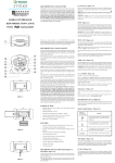
1
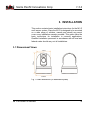
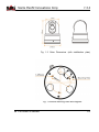
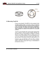
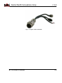
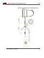
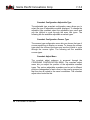
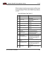
M1-D MANUAL REVISION 1.3.2 SIERRA PACIFIC INNOVATIONS 6620 S. TENAYA WAY 100 LAS VEGAS, NV 89113 702-369-3966 WWW.X20.ORG [email protected] CORP Sierra Pacific Innovations Corp 1.3.2 TABLE OF CONTENTS 1. SAFETY NOTES – IMPORTANT ............................................................... 4 2. ABOUT THE M1-‐D ................................................................................. 5 2.1 FEATURES .............................................................................................. 5 2.2 FUNCTIONS ............................................................................................ 6 Thermal Imaging Sensor .................................................................... 6 Visual CCD Sensor .............................................................................. 6 Laser Indicator ................................................................................... 6 Thermal Zoom .................................................................................... 6 Inverted Operation ............................................................................. 7 Auto Tours .......................................................................................... 7 On Screen Display Symbology ............................................................ 7 2.3 TECHNICAL SPECIFICATIONS ...................................................................... 8 3. INSTALLATION ...................................................................................... 9 3.1 DIMENSIONAL VIEWS ............................................................................... 9 3.2 MOUNTING THE M1-‐D ......................................................................... 11 Mounting Steps ................................................................................ 12 3.3 ELECTRICAL CONNECTIONS ..................................................................... 13 Electrical Steps ................................................................................. 13 Electrical Connections Overview Diagram Fig. 1.6 ........................... 15 4. OPERATION ........................................................................................ 16 4.1 BASIC OPERATION ................................................................................. 16 Pelco-‐D Specialty Command Mapping ............................................. 16 Power On the M1-‐D ......................................................................... 17 Pan Tilt The M1-‐D ............................................................................ 17 Select Video Source .......................................................................... 17 Trigger The Laser Pointer ................................................................. 18 Thermal Imaging Sensor Zoom ........................................................ 18 Thermal Imaging Color Palletes ....................................................... 19 4.2 ONSCREEN SYMBOLOGY ......................................................................... 21 Heading Indicator ............................................................................ 21 Numeric Pan Tilt Indicator ............................................................... 22 Cross Hairs ....................................................................................... 22 Zoom Indicators ............................................................................... 22 Logo ................................................................................................. 22 Text String ........................................................................................ 22 Accessing The On Screen Display Menu ........................................... 23 Navigating The OSD Menus ............................................................. 23 M1-D User’s Guide 2 Sierra Pacific Innovations Corp 1.3.2 Symbology OSD Menu ...................................................................... 24 Symbology Crosshair Menu ............................................................. 24 Symbology Zoomer Menu ................................................................ 25 Symbology Pan Position Menu ......................................................... 25 Symbology Numeric Position Menu ................................................. 25 Symbology Text Menu ...................................................................... 25 Symbology Logo Menu ..................................................................... 26 Crosshair Configuration Menu ......................................................... 26 Crosshair Configuration Fixed Type ................................................. 26 Crosshair Configuration Adjustable Type ......................................... 28 Crosshair Configuration Zoomer Type ............................................. 28 Crosshair Adjust Menu ..................................................................... 28 Cross Grouping ................................................................................. 29 Crosshair Adjust Setting Crosshair Positions .................................... 29 Crosshair Adjust Reset All Submenu ................................................. 30 4.3 ADVANCED OPERATION ......................................................................... 30 Setting Preset Positions ................................................................... 31 Calling Preset Positions .................................................................... 31 Advanced Preset Call Number Codes ............................................... 31 Preset Call Number Code Table 1.5 .................................................. 32 Preset 81 Video Switch ..................................................................... 33 Preset 82 Auto Scan ......................................................................... 33 Preset 84 Pattern Scan 1 .................................................................. 33 Preset 85 Pattern Scan 2 .................................................................. 33 Preset 86 Pattern Scan 3 .................................................................. 34 Preset 87 Pattern Scan 4 .................................................................. 34 Preset 89 Clear Presets .................................................................... 34 Preset 90 OSD On/Off ...................................................................... 34 Preset 94 Remote Reboot ................................................................ 34 Preset 96 180 Degree Continuous Scan ........................................... 35 Preset 97 360 Degree Random Scna ................................................ 35 Preset 98 90 Degree Continuous Scan ............................................. 35 Preset 99 OSD .................................................................................. 35 M1-D User’s Guide 3 Sierra Pacific Innovations Corp 1.3.2 1. SAFETY NOTES – IMPORTANT The following safety precautions must be followed carefully. Please take the time to review the entire manual before operation. Before installing the M1-D camera system please read this manual carefully and familiarize yourself with its features and operations. The installation of the M1-D must be performed by qualified service or system integrators and shall comply with all local codes. Before powering on the camera verify the power voltage, current and polarity are correct. Route the power, video and control cables in an appropriate manner to avoid damage to the cable. Make sure the cable is not a trip hazard. Do not operate the camera outside of the systems specified environmental range. The M1-D’s working temperature range is -25°C - 70°C. The ambient humidity limit is <95% non-condensing. During transportation avoid violent shock and/or vibration to the camera system. To prevent electric shock and avoid permanent damage to the M1-D, do not remove any screws or attempt to disassemble the system housing. There are no user serviceable parts inside. Contact SPI Corp for service at 702-3693966. Video and RS-485 control cables should be separated from other cables. Shielding may be necessary in some cases to avoid interference. NEVER aim the lens of the M1-D at the sun or extremely hot objects. This may damage the precision thermal sensor. To clean the M1-D use a soft cloth. For extreme dirt utilize a weak solution of water and household dish soap. Use only quality lens care tissue or lens cloth to wipe the windows of the M1-D. Do not rotate the camera housing manually. Do not hold the camera module while in operation or try to stop the rotation while in operation. This may result in a malfunction of the camera. M1-D User’s Guide 4 Sierra Pacific Innovations Corp 1.3.2 Shield the camera from radiation, X-Ray, Radar or other strong electromagnetic sources. 2. ABOUT THE M1-D The M1-D is an intelligent Pan Tilt Zoom multisensor imaging platform designed for all weather operation on a variety of platforms. The M1-D is ideally suited for Vehicle, Vessel or stationary mounting configurations. The M1-D features a thermal day/night sensor, a visual light CCD sensor and a laser indicator. The M1-D PTZ is remotely controlled via optional accessory keyboards or via user supplied devices that communicate via RS/485 utlizing the Pelco-D protocol. 2.1 Features § Fully weatherized housing for outdoor operation, antivibration, anti-corrosion IP66 rated. § Thermal imaging sensor for detailed imagery in any lighting condition. § CCD Visual sensor for target identification. § Laser indicator for team security and object tracking. § Continuous 360° pan with 90° tilt range. § 12VDC operation with vehicle cigarette lighter support. § User adjustable preset positions with auto tour. § Digital Zoom. § Compact 4.5” gimbal ball design with a light weight of approximately 2 lbs. for easy integration into a variety of platforms. M1-D User’s Guide 5 Sierra Pacific Innovations Corp 1.3.2 2.2 Functions Thermal Imaging Sensor The M1-D is equipped with a next generation LWIR (Long Wave InfraRed) thermal imaging sensor operating in the 8-12 micron wavelength. This sensor “sees” heat energy not light. This unique capability allows you to visualize the world around you regardless of ambient lighting. Visual CCD Sensor The M1-D is equipped with a visual imaging sensor that sees in the visual light spectrum. This sensor is ideally suited for object identification and for reading vehicle tags, ship or aircraft numbers. Laser Indicator The M1-D is equipped with a red dot visible light laser pointing device. The laser can be triggered to pin point areas of interest to other personal working together as a team. Thermal Zoom The M1-D incorporates the latest in Digital thermal zoom technology. The zoom level can be triggered from the remote control and increases awareness by factors of 2x, 4x, 8x (depending on model). M1-D User’s Guide 6 Sierra Pacific Innovations Corp 1.3.2 Inverted Operation The standard orientation for the M1-D is in the upright position with the base plate resting on a surface below (such as a vehicle roof). The system is capable of inverted operation wherin the base plate is mounted above (such as in a UAV or Aircraft). Inverted operation must be ordered from the factory. Please contact SPI CORP 702-369-3966 to switch to inverted operation. Auto Tours The M1-D can be configured to automatically scan between selected preset stops. The user defines the stops so that you can set the system to continuously scan certain areas of interest. In addition the M1-D can be setup to automatically pan 90°, 180° or 360°. On Screen Display Symbology The M1-D has a variety of user adjustable on screen display symbols that greatly aid in scene visualization. The symbology includes multiple crosshairs (boresightable to the laser indicator), zoom FOV indicators, pan position indicator, user input text string, laser firing indicator and logos. The symbology is controlled via the onscreen menu system. M1-D User’s Guide 7 Sierra Pacific Innovations Corp 1.3.2 2.3 Technical Specifications 160x120 320x240 640x480 Thermal Performance Detector Microbolometer Long Wave InfraRed 320x240 640x480 Resolution 160x120 Spectral Response 8-12 microns (LWIR) 19mm or 25mm 19mm or 25mm Thermal Optics 19mm or 25mm 24° HFOV 32° HFOV 19mm FOV 12° HFOV 18° HFOV 25° HFOV 25mm FOV 9° HFOV Visual Performance Sensor Resolution FOV 1/3” CMOS 520 TV Lines 20° HFOV Pan Tilt Pan Range Tilt Range P/T Speed Auto Cruise Pattern Scans Presets Interface Video Communication Environmental Size Weight Operating Temp. M1-D User’s Guide 360° Continuous Rotation 90° Tilt Range PAN:0.05o~240o/sec;TILT:0.03o~160o/sec 1-39 preset positions scan in sequential order 4 programable routes. Up to 100 Single channel NTSC RS/485 2400bps Pelco-D protocol 4.5” Gimbal (130mm x 116mm x 163mm) 2lbs. (19mm system) -25°C to +60°C 8 Sierra Pacific Innovations Corp 1.3.2 3. INSTALLATION This section contains basic installation instructions for the M1-D multi sensor system. Since the M1-D is designed to be mounted on a wide range of vehicles, vessels and aircraft we cannot cover every installation scenario possible. This guide offers the basic instructions for installation in common applications. Qualified installation personnel in accordance with all local and federal codes should carry out all installations. 3.1 Dimensional Views Fig. 1 Outer dimensions (no stabilization plate) M1-D User’s Guide 9 Sierra Pacific Innovations Corp 1.3.2 Fig. 1.2 Outer Dimensions (with stabilization plate) Fig. 1.3 Bottom mounting holes and magnets. M1-D User’s Guide 10 Sierra Pacific Innovations Corp 1.3.2 Fig. 1.4 Stabilization plate mounting holes 3.2 Mounting The M1-D First you must decide if the M1-D is to be mounted in the standard upright position or inverted. In order to mount the unit inverted you must specify inverted operation at time of order or send the unit back to SPI Corp for modification. Inverted operation is normally associated with UAV usage when mounted to the bottom of Aircraft. M1-D is not aircraft certified. The M1-D comes standard with a high strength magnetic base mount consisting of three high power magnets embedded into the base of the unit. These magnets are suitable for mounting the M1-D on metallic surfaces (such as a vehicle roof) for on road use in non violent conditions. For a more permanent mount or for use in extreme motion environments you will want to use the bolt holes on the bottom of the unit to affix the M1-D to a bracket (of your own fabrication). SPI Corp offers a vibration mitigation stabilization plate which also acts as a hard mounting plate for the M1-D. Contact SPI Corp at 702-369-3966 to purchase this accessory. M1-D User’s Guide 11 Sierra Pacific Innovations Corp 1.3.2 Mounting Steps 1. Find a suitable flat location that is free from obstruction on all sides. You will want this area to be parallel with the ground so as not to skew the image as you pan. Make sure that the area is firm and not flexible since flexing of the mounting surface will cause jitter in the video image during use. 2. If using the magnetic mounts carefully tilt the M1-D into position. DO NOT PINCH YOUR FINGERS. The magnets will grab with some force. 3. If using the mounting holes first mount the M1-D to your mounting fixture then mount the fixture to your surface. We recommend fabricating a “spider” type bracket that extends out beyond the edge of the M1-D (see Fig. 1.4.1). If you have access to the underside of your mounting platform you can mark and drill holes to mount your bolts through the mounting plate and up into the bottom of the M1-D. 4. Route the main system cable into the vehicle or other protected area. Be careful to not put undue strain on the cable or bend the cable severely. Fig. 1.4.1 Sample spider mount design. Not to scale. M1-D User’s Guide 12 Sierra Pacific Innovations Corp 1.3.2 3.3 Electrical Connections The M1-D operates on 12VDC power typical of most vehicles. The M1-D is a negative ground system so verify that your vehicle outputs the correct voltage and polarity. The M1-D outputs standard NTSC video signal and responds to commands via 2 wire RS/485 serial interface utilizizing the Pelco-D protocol at 2400bps. Electrical connections should always be performed by qualified personel in accordance with local and federal codes. Electrical Steps 1. Review Electrical Connections Overview Diagram (Fig. 1.6) 2. Route main system cable into protected area. 3. Connect the pigtail cable extender (Fig. 1.5) to 12VDC power. The included pigtail cable extender utilizes a phono plug type connector and includes a cigarette lighter adapter. For more permanent installation this connector can be cut off and hard wired to the vehicle. OBSERVE POLARITY OR SYSTEM DAMAGE WILL OCCUR. CONSULT A QUALIFIED ELECTRICIAN. 4. Connect the RS/485 cables to the appropriate port of your controller. The RS485 leads are red and black in color. The red wire is RS485 + and the black wire is RS485 -. 5. Connect the BNC video plug to a suitable NTSC video monitor. 6. Connect the pigtail cable extender to the main system cable. The unit will power on when this connection is made. There is no ON/OFF switch on the M1-D main system cable. The system is powered off by removing power from the cable or disconnecting the M1-D pigtail cable extender from the main cable. To install a dash mounted or other power switch make your connection or relay in line with the 12VDC power connections after the pigtail cable extender. M1-D User’s Guide 13 Sierra Pacific Innovations Corp 1.3.2 Fig. 1.5 Pigtail Cable Extender. M1-D User’s Guide 14 Sierra Pacific Innovations Corp 1.3.2 Electrical Connections Overview Diagram Fig. 1.6 M1-D User’s Guide 15 Sierra Pacific Innovations Corp 1.3.2 4. OPERATION This section contains the information required to operate the M1-D mult-sensor pan tilt zoom system. Please read and familiarize yourself with the entire manual before operating the M1-D system. 4.1 Basic Operation The M1-D multi sensor pan tilt zoom system is comprised of the following subsystems. 1. Thermal infrared imaging sensor with dgital zoom and fixed focus optics. 2. Visual light CMOS sensor with focus free optics. 3. Laser pointer 4. Pan Tilt remote controlled positioning housing. The M1-D is a remote controlled imaging system that provides the user with thermal imaging video, daytime video and laser pointer technology. The system is controlled via joystick or keyboard controls allowing the user to operate the system remotely. Pelco-D Specialty Command Mapping The various subsystems are controlled via buttons on standard Pelco-D compliant controllers, DVR’s or computer software. Special commands exclusive to the M1-D are mapped to specific Pelco-D commands in order to maximize compatiblitiy. The M1-D uses the following Pelco-D commands to directly access specialized features of the system. M1-D User’s Guide 16 Sierra Pacific Innovations Corp 1.3.2 IRIS OPEN – The [IRIS OPEN] command (typically labelled as [OPEN] on keyboard controllers) is used to control the thermal imaging sensor zoom. IRIS CLOSE – The [IRIS CLOSE] command (typically labelled as [CLOSE] on keyboard controllers) is used to control the thermal imaging sensor color palletes. FOCUS FAR – The [FOCUS FAR] command (typically labelled as [FAR] on keyboard controllers) is used to activate the laser pointer. FOCUS NEAR – The [FOCUS NEAR] command (typically labelled as [NEAR] on keyboard controllers) is used switch between the visible and thermal imaging sensors. Power On the M1-D To power on the M1-D you need to connect power to the system by plugging in the cigarette lighter vehicle adapter. If you have installed a remote power switch use that to turn on the system. Once turned on the M1-D will begin its self test routine. You will see the unit spin and tilt as it runs the self test. Once it stops moving the M1-D will be ready for operation. Pan Tilt The M1-D Using a joystick controller you can remotely position the M1-D in the pan and tilt access by using the joystick on your control keyboard. Pushing the joystick to the right will cause the unit to pan to the right. Pushing the joystick up will cause it to tilt upward. You can invert these operations with a special menu command (see Advanced Settings Menu Preset Commands). Select Video Source The M1-D has both a thermal imaging sensor and a visual light sensor. Video is output from the M1-D via a single video line. By sending a command to the M1-D you can switch between the M1-D User’s Guide 17 Sierra Pacific Innovations Corp 1.3.2 visual video and the thermal imaging video being output on the M1-D video output line. To switch between thermal imaging and visual video use the FOCUS NEAR command (typically labelled [NEAR] on keyboard controllers). Each time you push the button it sill switch between visual and thermal video. Trigger The Laser Pointer The M1-D has a visible light red dot laser pointer integrated into the system. WARNING LASER RADIATION EMITTED FROM THE FRONT OF THE SYSTEM. DO NOT FIRE LASER WHEN ANY PERSON IS STANDING IN FRONT OF THE SYSTEM. DO NOT LOOK INTO LASER APERATURE. DO NOT FIRE LASER AT ANY PERSONS FACE. The laser is triggered using the FOCUS FAR command (typically labelled [FAR] on a keyboard controller). The laser will fire only as long as you send the command (by computer or by holding the [FAR] button). While the laser is firing the word LASER will appear on screen in the top right corner. The cross hair symbology onscreen can be bore sighted to the laser for your individual application. Please see Advanced Symbology Menu Settings for more information. Thermal Imaging Sensor Zoom The M1-D has an electronic zoom on the thermal imaging video channel. You can cycle through the various zoom levels via the IRIS OPEN command (typically labelled [OPEN] on keyboard controllers). Each time you push the [OPEN] button the system cycles to the next zoom level. When you reach maximum electronic zoom the next push of the [OPEN] button returns to normal 1x no zoom imaging. The amount of electronic zoom is dictated by the thermal sensor inside the M1-D. The following outlines part number and corresponding sensor / zoom levels. PART # M1-D-XX-16 M1-D-XX-32 M1-D-XX-64 M1-D User’s Guide SENSOR 160X120 320X240 640X480 ZOOM 2X 2X, 4X 2X, 4X, 8X 18 3—Basic Operation of the Tau 640 and GUI Sierra Pacific Innovations Corp 1.3.2 Polarity/LUT: The Tau 640 camera detects an temperatures in a given scene. Within the camera, T are mapped (as determined by the AGC algorithm se 0 to 255 values. In a black and white display mode, Part # Sensor and Zoom level Table 1.3 converted to shades of grey with, for example, 0 be Polarity/LUT: The Taubeing 640 totally camera detects the 255 white. The and 0 toimages 255 grayshades r temperatures in a given scene. Within the camera, these temperatures referenced to a Look-Up Table (LUT) permanently st 3—Basic OperationThermal of the TauImaging 640 and GUI Tau 640 User’s Manua Color Palletes are mapped (as determined by the algorithm selected) a range LUT of to convert theAGC scene to a video image.toDifferent 0 to 255 values. In achange black and white display mode, this range is the appearance of the displayed image. The The M1-Dconverted thermal to imaging isisaeither full color thermal imager shades sensor of grey with, for example, 0 being totally black and selection White objects 3—Basic Operation of theHot Tau(hotter 640 and GUI appear Polarity/LUT: The Tau 640 camera detects and images the 255 being totally white. The 0 to 255 grayshades range sensed is obje capable of black and white objects and multiple thermal color profiles. inthese the video display) or Black Hot (hotter temperatures in a given scene. Within the camera, temperatures referenced to a Look-Up Table (LUT) permanently stored in the camera 3—Basic Operation of the Tau 640 and GUIcycle through the various Tauobjects). 640 User’s Manual You can color profiles in the thermal between t than cooler are mapped (as determined by the AGC algorithm selected) toDifferent a Since range the of difference to convert the scene tothe a video image. LUTs are or available to imaging sensor by pushing IRIS CLOSE button (typically simply reverses the choice of darker lighter foran te Polarity/LUT: 640most camera detects 0 to 255 values. In achange black and display mode, this rangeThe is TauThe thewhite appearance of the displayed image. common extremes, this to ascamera, Polarity. on for keyboard controllers). Each time you push temperatures inis asometimes given scene. Within the converted labelled to shades[CLOSE] of grey with, example, 0 being totally black andreferred selection is either White Hot (hotter objects appear brighter than cooler Polarity/LUT: The Tau 640 camera detects and images the are available as shown below. the [CLOSE] button the M1-D will cycle through color profiles are mapped (as determined by the AGC algorithm 255 being totally white. The 0 to 255 grayshades range sensed is objects appear darker se objects in the video display) or Black Hot (hotter temperatures in a given scene. Within the camera, these permanently temperatures to 255 values. In aand black and white display mode, referenced to a you Look-Up (LUT) stored in the camera until get back around to 0 the original black white pallete. thanTable cooler objects). Since the difference between these two modes are mapped (as determined by the AGC algorithm selected) to a range of Figure 3-7 shows each of the LUTs as displayed converted to shades of grey with, for example, 0inbeT to convert The the scene to a video image. Different LUTs arepalletes available to following outlines the available color and theFusion, order Rainbow, simply reverses the choice of darker or lighter forHot, temperature 0 to 255 values. In achange black and white display mode, this range is upper left: White Hot, Black G 255table being totally white. Theonly). 0 to 255color grayshades ra the(color appearance of the displayed image. The most extremes, this is sometimes referred to as Polarity. Other LUTs palletes may change this is for common reference converted to shades selection of grey with, for example, 0 being totally black and Color2, Ice Fire, Rain, Red Hot, and Green Hot. Sele referenced to a Look-Up Table (LUT) permanently sto is either White (hotter appear brighter than cooler are Hot available asobjects shown below. 255 being totally white. The 0 grayshades is menu to view image using the LUTLUT yo to convert theyour scene to a displayed video image. Different objects in to the255 video display) orrange Black sensed Hot (hotter objects appear darker referenced to a Look-Up Table (LUT) permanently stored in the camera mode will not affect the digital data output. change appearance of the displayed image. than cooler objects). Figure Since the between these twodisplayed modes 3-7difference shows each ofto thethe LUTs as in Test Pattern RampThe Mo to convert the scene simply to a video image. Different LUTs are or available selection is either White Hot (hotter objects appear reverses the choice of darker lighter for temperature upper left: White Hot, Black Hot, Fusion, Rainbow, Globow, Ironbow1, Iron change the appearance of the displayed image. The most common in Other the display) or Black obje extremes, this is sometimes referred to asobjects Polarity. color LUTs Color2, Icebrighter Fire, Rain, Red Hot, andvideo Green Hot.Cold Select oneHot of (hotter these Cold LUTs Cold selection is either White Hot (hotter objects appear than cooler WHITE HOT than cooler objects). Since the difference between t are available as shown below. menu to view your image displayed using the LUT you choose. The setting objects in the video display) or Black Hot (hotter objects appear darker simply reverses the choice of darker or lighter for te mode willthese not affect the digital data output. than cooler objects). Figure Since the between twodisplayed modes extremes, thisPattern is sometimes referred to as with Polarity. 3-7difference shows each of the LUTs as in Test Ramp Mode starting the simply reverses the choice darker lighter forHot, temperature are available as shown below. upper of left: WhiteorHot, Black Fusion, Rainbow, Globow, Ironbow1, Ironbow2, Sepia, Hot HotColor1, extremes, this is sometimes referred to as Red Polarity. color LUTs Color2, Ice Fire, Rain, Hot,Other and Green Hot.Cold Select one of these LUTs from the pull-down Cold BLACK HOT Cold White Hot Cold Black Hot are available as shown below. Figure each the LUTs as Polarity/LUT displayed in T menu to view your image displayed using the LUT3-7 youshows choose. Theofsetting of the 3—Basic Operation of the Tau 640 and GUI PALLETE DESCRIPTION Cold Cold G Cold left: White Hot, Black Hot, Fusion, Rainbow, mode will not affect the digital data output.upper Figure 3-7 shows each of the LUTs as displayed in Test PatternColor2, Ramp Mode starting with the Ice Fire, Rain, Red Hot, and Green Hot. Sele upper left: White Hot, Black Hot, Fusion, Rainbow, Globow, Ironbow1, Ironbow2, Hot HotColor1, HotLUT yo menu to view yourSepia, image displayed using the Color2, Ice Fire, Rain, Red Hot,FUSION and Green Hot. Select one of these LUTs from the pull-down Cold Cold Cold Cold mode will notBlack affect the digital data output. White Hot Hot Fusion Hot Hot menu to view your image displayed using the LUT you choose. The setting of the Polarity/LUT Cold Cold Cold Cold mode will not affect the digital data output. Globow Ironbow1 Hot Cold Cold RAINBOW White Hot Cold Hot Hot Cold Globow Cold Hot Hot Globow Cold Ironbow1 Cold Cold Cold Hot Color2 Cold Hot Fusion Hot Cold Ironbow1 Hot Cold Cold Cold Color1 Cold Hot Ironbow2 Color2 Hot Fusion Cold Cold Hot Hot Ironbow2 Hot Cold Cold Cold Cold Hot Hot Hot Cold Black Hot Color2 Cold Hot Sepia GlobowHot Hot Red Hot Cold Sepia Ice Fire Ironbow2 Cold Cold Hot Color2 Hot Hot Rainbow White Hot Cold Color1 Hot Hot Cold Cold Cold Hot Ironbow1 Hot Cold Cold Rainbow Cold Cold Hot Color1 Globow Cold Cold M1-D User’sColdGuide Cold Black Hot Hot Cold Hot Color1 Cold Cold Cold GLOWBOW Black Hot Hot White Hot Cold Hot Ice Fire Hot Hot Ironbow1 Hot Green Hot Cold Figure 3-7: Hot Look-Up T Rain 19 Simple experimentation Hot Hotwith this feature while viewin Hot click the Save Settings Hot Remember that you must bu Red Hot Green Hot Color1 Color2 settings as the default at power-up. Hot Hot Ice Fire Cold Figure 3-7: Look-Up Table Options Cold Rain Simple experimentation Hot Hotwith this feature while viewing the video image wi Remember that you must Setup tab June 2011 Red Hot Green Hot3-18 click the Save Settings button on the settings as the default at power-up. Figure 3-7: Look-Up Table Options Hot Red Hot Hot Green Hot mode not affect the digital data output. to 255 values. In abetween black will and white display mode, this range is than cooler objects). 0 Since the these two modes change appearance of the displayed image. most common Figure 3-7difference shows each of thethe LUTs as displayed in Test Ramp Mode starting with the extremes, thisPattern is sometimes referred to as Polarity. Polarity/LUT: The TauThe 640 camera detects an converted to shades of grey with, for example, 0 being totally black and simply reverses the choice of darker or lighter for temperature selection is either White Hot (hotter objects appear brighter thancamera, cooler upper left: White Hot, Black and Hot,images Fusion, the Rainbow, Globow, Ironbow1, Ironbow2, Color1, are available asinshown temperatures a givenbelow. scene. WithinSepia, the Polarity/LUT: The Tau 640 camera detects 255 being totallyto white. The 0 255color grayshades sensed is objects appear darker extremes, this is sometimes referred asobjects Polarity. Other LUTs in to the display) orrange Black Hot (hotter Color2, IceWithin Fire, Rain, Red Hot, andvideo Green Hot. Select one of these LUTs from thealgorithm pull-down mapped determined by the AGC Cold Cold Cold Coldse temperatures in a given scene. the 3—Basic camera, these temperatures Operation ofare the Tau 640(as and GUI T referenced to a Look-Up Table (LUT) permanently stored in the camera are available as shown below. than displayed cooler objects). Since the difference between these two modes menu to view your algorithm image using the LUT youvalues. choose. The of the Polarity/LUT 0 to 255 In a black and white display mode, Figure 3-7 shows each ofsetting the LUTs as displayed in T are mapped (as determined by the AGC selected) to a range of to convert the scene simply to a video image. Different LUTs are or available to reverses the choice of darker lighter forHot, temperature converted to shades ofBlack grey with, for example, 0 be not affect the digital data output. upper left: White Hot, Fusion, Rainbow, G 0 to 255 values. In amode black will and white display mode, this range is change the appearance of the displayed image. The most common Figure 3-7 shows each of the LUTs as displayed in Test Ramp Mode starting with the extremes, thisPattern is sometimes referred to as Polarity. Other color LUTs 255 being white. TheHot, 0 to 255 grayshades r Color2, Ice totally Fire, Rain, Red and Green Hot. Sele converted to shades selection of grey with, for example, 0 being totally black and Polarity/LUT: The Tau 640 camera detects and images the is either White (hotter appear brighterSepia, than cooler upper left: White Hot, Black Hot, Fusion, Rainbow, Globow, Ironbow1, Ironbow2, are Hot available asobjects shown below. Hot HotColor1, HotLUT yo referenced to your a Look-Up Table (LUT)using permanently st menu to view image displayed the 255 being totally white. The 0 to 255 grayshades range sensed is temperatures in a given scene. Within the camera, these temperatures in the display) or Black Hot (hotter objects appear darker Color2, Ice Fire, Rain,objects RedCold Hot, andvideo Green Hot.Cold Select one of these LUTs from the pull-down Cold to convert the scene to digital a Cold video image. mode will not affect the data output. White Black Hot Fusion referenced to a Look-Up Table (LUT) permanently stored indetermined theHot camera are mapped (as bythese the AGC algorithm selected) toDifferent a range LUT of than cooler objects). Since the difference between two modes menu to view your image displayed using the LUT3-7 you shows choose. The setting of the Polarity/LUT Figure each of the LUTs as displayed in Test Pattern RampThe Mo change the appearance of the displayed image. to convert the scene simply to a video image. Different LUTs are available to 0 to 255 values. In a black and white display mode, this range is Cold Cold Cold Cold reverses the choice of darker lighter forHot, temperature IRONBOW 1 mode will not affect the digital data output. upper left: WhiteorHot, Black Fusion, Rainbow, Globow, Ironbow1, Iron selection is either White Hot (hotter objects appear change the appearance of the displayed image. The most common converted to shades grey with, for color example, 0 being totally black and extremes, this is sometimes to asofRed Polarity. Other LUTs Color2, referred Ice Fire, Rain, Hot, andvideo Green Hot. Select oneHot of these LUTs Cold Cold Cold objects in to the display) orrange Black (hotter obje selection is either White Hot (hotter objects appear brighter than cooler 255 being totally white. The 0 255 grayshades sensed is are available as shown below. Hot Hot displayed using the HotLUT you choose. The Hot setting menu to view your image than cooler objects). Since the difference between t objects in the video display) or Black Hot (hotter objects appear darker referenced to a Look-Up Table (LUT) permanently stored in the camera Cold Cold Cold Cold data mode will notBlack affect the digital output. White Hot Hot Fusion Rainbow simply reverses the choice of darker or lighter for te Hot Hot to Hota video than cooler objects). Figure Since the difference between these two modes to convert the scene to image. Different LUTs are available 3-7 shows each of the LUTs as displayed in Test Ramp Mode starting the extremes, thisPattern is sometimes referred to aswith Polarity. Cold darker or lighter the appearance ofCold theGlobow, displayed image.Cold The most common simply reverses the choice forHot, temperature Globow Ironbow1 Ironbow2 2 Cold upper of left: IRONBOW White Hot,change Black Fusion, Rainbow, Ironbow1, Ironbow2, Sepia, Color1, Hotbelow. Hot are available asobjects shown either White Hot (hotter appear than cooler extremes, this is sometimes to asselection Polarity. color LUTs Cold Cold Cold Cold Color2, referred Ice Fire, Rain, Red Hot,isOther and Green Hot. Select one of Hot these LUTsbrighter from the pull-down Cold Cold Cold Cold White Black Hot objects in the video display) or Black Hot (hotter objects appear darker are available as shown below. Hot Hot displayed using the HotLUT you choose. The Hot setting of the Polarity/LUT menu to view your image Figure 3-7difference shows each ofCold the these LUTs as in T Cold than cooler objects). the between twodisplayed modesCold White Hot Hot Fusion Rainbow mode will notBlack affect the digital data output.Since Hot Hot Hot Hot upper left: White Hot, Black Hot, Fusion, Rainbow, G simply in reverses the choice darker or lighter Figure 3-7 shows each of the LUTs as displayed Test Pattern RampofMode starting withfor thetemperature Cold Cold Cold Cold Color2, Ice Fire, Rain, Red Hot, and Green Hot. Sele Globow Ironbow1 Ironbow2 Sepia color Hot extremes, this isIronbow1, sometimes referred to asHot Polarity. LUTs upper left: White Hot, Black Hot,SEPIA Fusion, Rainbow, Globow, Ironbow2, Sepia, Color1, Other Hot Hot Hot Hot menu to view your image displayed using the LUT yo are available as shown below. Color2, Ice Fire, Rain, RedCold Hot, and Green Hot.Cold Select one of Hot these Cold LUTs from the pull-down Cold White Black Hot Fusion Color1 Color2 Ice Fire mode will not affect the digital data output. Hot Hot menu to view your image displayed using the LUT you choose. The setting of the Polarity/LUT Cold Cold ColdMo Cold Cold Cold Figure 3-7 shows each of the LUTs as displayed in Test Pattern Ramp Globow Ironbow1 mode will not affect the digital data output.Hot Hot Hot Hot upper left: White Hot, Black Hot, Fusion, Rainbow, Globow, Ironbow1, Iron Cold Cold Cold Cold Cold Cold Globow Ironbow11Color2, COLOR IceIronbow2 Fire, Rain,Hot Red Hot, Sepia and GreenHot Hot. Select one of these Hot Hot LUTs Cold Cold Cold menu to viewBlack yourHot image Cold displayed using LUT you choose. The setting White Hot Fusion Rainbow Color1 Color2 Ice Fire the Rain Hot Hot Hot mode will not affect the digital data output. Sierra Pacific Innovations Corp Cold Cold Cold COLOR 2Hot Hot White Hot Color1 Cold Cold Cold Cold Black Hot Color2 Hot Cold Cold Cold 1.3.2 GlobowHot Cold Red Hot Fusion Ice Fire Ironbow1 Hot Cold Ironbow2 Hot Hot Hot Green Hot Hot Cold Cold Cold Color1 Color2 White Hot Black Hot Cold Hot Cold Hot Cold Figure 3-7: Look-Up Table Options Cold Cold Cold Rainbow Cold Cold Rain Hot Hot Hot Simple experimentation with feature while viewing the video image wi ColdthisIronbow2 GlobowHot Cold Ironbow1 Hot Sepia Hot click the Hot Remember that you must Save Settings button on the Hot Setup tab Red Hot Green Hot Hot Hot Hot Cold as the default Color1 at Cold Ice Fire power-up.Color2 Hot Cold ICE FIREsettings Hot White Black Hot Fusion Figure 3-7:Hot Look-Up Table Options Hot Cold Globow Ironbow1 Hot Cold Hot Cold Hot Cold Hot Red Hot Green Hot Simple experimentation with this feature while viewing the video image Cold Coldwill give you familiarity. Cold GlobowHot Ironbow1 Hot Ironbow2 Sepia Hot click the Save Settings Hot Hot Hot Remember that you button on the Setup tabFigure to save theLook-Up LUT 3-18 June 2011 TAU-064 3-7: T Red Hot Green Hotmust Cold asRAIN Cold settings the default power-up.Color2 Color1 at Cold Ice Fire Rain Figure 3-7: Look-Up Table OptionsSimple Hotwith this feature while Hot viewin Hot experimentation Cold Hot Cold Cold Cold Cold Hot Hot Hot click the Hot Remember that you must Save Settings bu Globow Ironbow1 Ironbow2 Hot Green Hot Simple experimentation with this feature while viewing theRed video image will give you familiarity. settings as the default at power-up. Color1 Color2 Cold Cold Cold Hot click the Save Settings Hot Coldbutton on the Hot Hot Remember that you must Setup tabFigure to save theLook-Up LUT 3-18 June 2011 TAU-0640-00-10, version 110 3-7: Table Options Cold Cold settings as the default RED HOT Color1 at power-up. Color2 Ice Fire Rain Cold 3-18 Cold Simple experimentation with this feature while viewing the video image wi Hot Hot Remember that you must button on the Setup tab 3-18 June Red Hot Green Hot Hot click the Save Settings Hot Hot2011 settings as the default at power-up. June 2011 FigureColor1 TAU-0640-00-10, version 110 Ice Fire 3-7: Look-Up Table Color2 Options Hot Cold GREEN HOT Cold Red Hot Hot Green Hot Simple experimentation Hot Hotwith this feature while viewing the video image will give you familiarity. 3-7: T 3-18 June 2011 TAU-064 Remember that you must click the Save Settings button on the Setup tabFigure to save theLook-Up LUT Red Hot Green Hot settings as the default at power-up. Figure 3-7: Look-Up Table OptionsSimple experimentation with this feature while viewin Hot Hot click the Save Settings bu Remember that you must Hot Green Hot Simple experimentation with thisPallette feature Description while viewing Table theRed video image will give you familiarity. 1.4 settings as the default at power-up. Remember that you must Setup tab to save the LUT 3-18 click the Save Settings button on the June 2011 TAU-0640-00-10, version 110 Figure 3-7: Look-Up Table Options settings as the default at power-up. M1-D User’s Guide 3-18 20 Simple experimentation with this feature while viewing the video image wi 3-18 June 2011 Remember that you must click the Save Settings button on the Setup tab settings as the default at power-up. June 2011 3-18 TAU-0640-00-10, version 110 June 2011 TAU-064 Sierra Pacific Innovations Corp 1.3.2 4.2 Onscreen Symbology The M1-D user interface screen contains a variety of useful symbology to aid in your mission. All symbology can be turned on or off based on user preference. Heading Indicator The heading indicator shows the position of the M1-D in relative pan axis. The pie shaped symbol will rotate around circle indicating the direction that the imaging sensors pointing. Take care when installing the M1-D so that heading indicator points to the front of the vehicle. M1-D User’s Guide the the are the 21 Sierra Pacific Innovations Corp 1.3.2 Numeric Pan Tilt Indicator The numeric pan/tilt indicator reads out the position of the pan tilt unit in degrees. The pan rotation is the first number on the left and reads from 0-365 degrees. The tilt axis is the second nember and reads from -15 (down) to +90 degrees (up). Cross Hairs The M1-D is equipped with a number of user selectable cross hair symbols. These symbols fall into two main groups (moveable and fixed). Moveable cross hair symbols can be adjusted in the X, Y axis to align the cross hair with the laser pointer at a given distance (AKA Bore Sight the laser). Fixed cross hairs remain in the center of the image. Zoom Indicators The M1-D is equipped with zoom indicator lines that appear to the outer edge of the cross hairs. The zoom indicator lines help to give the operator a reference as to the field of view of the next zoom level. Objects that are within the zoom lines should remain within the zoom lines after the zoom button is pushed. Logo The M1-D displays the SPI Logo in the bottom right corner of the screen. Text String The M1-D gives the user the ability to input a custom text string that will be displayed on the screen. This is useful for labelling individual cameras in multiple camera setups. M1-D User’s Guide 22 Sierra Pacific Innovations Corp 1.3.2 Accessing The On Screen Display Menu To adjust the settings of on screen symbology you need to access the OSD Menu (On Screen Display Menu). To access the OSD enter the Pelco-D command [CALL] + 99 + [ENTER] or [PRESET] + 99 + [ENTER]. Or 99 + [PRESET] or other variation depending on the setup of your keyboard. (For technical assistance contact SPI Corp 702-369-3966). Once you enter the OSD Menu you should have the following screen open. MAIN ∗∗∗∗∗∗∗∗∗∗∗∗∗∗∗∗∗∗∗∗∗∗∗∗∗∗ ∗ <SYMBOL> <CROSSHAIR CONFIG> EXIT OSD Menu Main Fig. 2.0 Navigating The OSD Menus To navigate through onscreen display (OSD) menus you utilize the joystick and keyboard buttons. The currently selected menu item is indicated by the presence of an asterisk (∗) symbol next to that menu item. To move to the next menu item you move the (∗) symbol up and down with the joystick. To select a menu item you push the IRIS OPEN (typically labelled [OPEN] on keyboard controllers). To change a menu selection use the joystick up and down commands. To back out of a menu option use the IRIS CLOSE command (typically labelled [CLOSE] on keyboard controllers). M1-D User’s Guide 23 Sierra Pacific Innovations Corp 1.3.2 Symbology OSD Menu The symbology OSD Menu allows you to turn on or off the various symbology items available in the M1-D system. The symbology menu also allows you to select between Fixed and Moveable Crosshairs. When you access the Symbology OSD Menu you will see the following choices. SYMBOLOGY ∗∗∗∗∗∗∗∗∗∗∗∗∗∗∗∗∗∗∗∗∗∗∗∗∗∗ ∗ CROSSHAIR FIXED ZOOMER ON PAN POSITION ON NUMERIC POSITION ON TEXT ENTERTEXT LOGO ON EXIT OSD Symbology Menu Fig. 2.1 Symbology Crosshair Menu The crosshair symbology menu lets you choose between a fixed crosshain, adjustable crosshair or no crosshair. There are three choices [FIXED] [ADJUST] [OFF]. [FIXED] crosshair setting activates the last selected fixed crosshair. [FIXED] crosshairs remain in the center of the image and cannot be moved. You can change the type of fixed crosshair in the CROSSHAIR CONFIGURATION MENU. [ADJUSTABLE] crosshairs can be boresighted to the laser or other devices as per your requirements. Adjustable crosshairs can be adjusted in the CROSSHAIR CONFIGURATION MENU. Selecting the Adjustable crosshair activates the last selected adjustable crosshair. You can select different adjustable crosshairs in the CROSSHAIR CONFIGURATION MENU. [OFF] Crosshairs turns all crosshairs off. M1-D User’s Guide 24 Sierra Pacific Innovations Corp 1.3.2 Symbology Zoomer Menu The Zoomer Menu controls the zoom Field Of View indicator which gives you an indication of what the field of view will be when you activate the thermal zoom. Objects that are within these boundries should appear in image when zoom is activated. The Symbology Zoomer Menu lets you turn this feature on or off. You can select the type of zoomer in the CROSSHAIR CONFIGURATION MENU. Symbology Pan Position Menu The pan position menu lets you turn on or off the pan position indicator located in the bottom left corner of the screen. Symbology Numeric Position Menu The numeric position menu lets you turn on or off the numeric pan tilt position indicator in the top left corner of the screen. Symbology Text Menu The text menu give you the option to enter a custom text string to be displayed on screen. The text string is limited to 12 characters (A-Z and 0-9). The text menu has three options; [ENTERTEXT] [ON] [OFF]. [ENTERTEXT] Allows you to enter the desired text string using the joystick keyboard controller. Select the desired character with the joystick and then press the [OPEN] button on the keyboard to select. To backspace and erase a character use the [CLOSE] button on the keyboard. When the desired text string is entered use the joystick to select SAVE AND EXIT then press the [OPEN] button to select and save. To cancel select the CANCEL AND EXIT option and press the [OPEN] button. [ON] Turns on the text string entered in the ENTERTEXT menu so that it appears on screen. [OFF] Turns off the text string. M1-D User’s Guide 25 Sierra Pacific Innovations Corp 1.3.2 Symbology Logo Menu The symbology logo menu allows you turn the on or off the SPI logo embedded in the bottom right corner of the screen. Crosshair Configuration Menu The crosshair configuration menu allows you to select the various crosshair and zoomer types of symbology inside the M1-D system. With the crosshair configuration menu you can choose different fixed and movable types of crosshairs as well as different types of zoomer brackets. The crosshair configuration menu is also where you adjust the position of movable crosshair types. When you enter the crosshair configuration menu screen it should look like this. CROSSHAIR CONFIGURATION ∗∗∗∗∗∗∗∗∗∗∗∗∗∗∗∗∗∗∗∗∗∗∗∗∗∗∗ ∗ FIXED TYPE CROSS BLUE ADJUSTABLE TYPE RED DOT ZOOMER TYPE ZOOMER BLUE <ADJUST> EXIT Crosshair Configuration Menu Fig. 2.2 Crosshair Configuration Fixed Type The fixed type crosshair configuration menu allows you to select the type of fixed crosshair displayed. To change the fixed type crosshair select the fixed type menu and use the joystick to cycle through the cross hair types. The following are the available crosshair and zoomer types. M1-D User’s Guide 26 Sierra Pacific Innovations Corp 1.3.2 Crosshair type chart Fig. 2.3 Zoomer type chart Fig. 2.4 M1-D User’s Guide 27 Sierra Pacific Innovations Corp 1.3.2 Crosshair Configuration Adjustable Type The adjustable type crosshair configuration menu allows you to select the type of adjustable crosshair displayed. To change the adjustble type crosshair select the adjustable type menu and use the joystick to cycle through the cross hair types. The following are the available adjustable crosshair types. Crosshair Configuration Zoomer Type The zoomer type configuration menu lets you choose the type of zoomer symbology to display on screen. To change the zoomer type select the zoomer type menu and use the joystick to cycle through the zoomer types. The following are the available zoomer types. Crosshair Adjust Menu The crosshair adjust submenu is accessed through the CROSSHAIR CONFIGURATION MENU. The crosshair adjust menu lets you adjust the position of the adjustable crosshair types. The various adjustable crosshairs can be set to different positions (independent of each other) or they can be grouped so that they are all locked to the same coordinates. The crosshair adjust menu looks like this. M1-D User’s Guide 28 Sierra Pacific Innovations Corp 1.3.2 CROSSHAIR ADJUST ∗∗∗∗∗∗∗∗∗∗∗∗∗∗∗∗∗∗∗∗∗∗∗∗∗∗∗ ∗ CROSS GROUPING YES CROSS ADJUST CROSS FULL ADJUST CROSS SQUARE ADJUST CROSS THICK ADJUST CROSS HALF ADJUST CHEVRON BLUE ADJUST CHEVRON RED ADJUST CROSS RED DOT ADJUST RED DOT ADJUST <RESET ALL> EXIT Crosshair adjust menu Fig. 2.5 Cross Grouping The cross grouping menu lets you set the adjustable crosshairs to be grouped or independent of each other. When grouped all adjustable crosshairs will align to the same point when you adjust one of them the others will also be aligned to that same point. To group all cross hairs set CROSS GROUPING to YES. When the crosshairs are not grouped you can set different adjustable crosshairs to different independent positions. To set crosshair positions independently set CROSS GROUPING to NO. Crosshair Adjust Setting Crosshair Positions The crosshair adjust sub menu allows you to set the position of the adjustable crosshair types. Once set the M1-D will remember the position until you change the position or reset the position. To adjust crosshairs independently make sure CROSS GROUPING is set to OFF. To make adjustments to the adjustable crosshair type on screen positions select the desired adjustable crosshair type with the joystick and press [OPEN]. M1-D User’s Guide 29 Sierra Pacific Innovations Corp 1.3.2 Each adjustable crosshair type has two options, ADJUST or RESET. To adjust the crosshair position select the ADJUST option with the joystick and press [OPEN]. The selected crosshair will appear onscreen and you can adjust its relative position by using the joystick up, down, left and right commands. Once the crosshair is in the desired position onscreen press the [OPEN] button to save that position and return to the Crosshair Adjust submenu. If you do not wish to save the position press the [CLOSE] button to return to the crosshair adjust submenu without saving the crosshair position. To reset a crosshair position to the center of the screen choose the RESET command with the joystick and press the [OPEN] button. Crosshair Adjust Reset All Submenu To reset all crosshairs to the center position select the <RESET ALL> submenu from the crosshair adjust menu and press the [OPEN] button. You will see a screen that asks you to CONFIRM AND EXIT or CANCEL AND EXIT. Select your desired choice and press the [OPEN] button to complete the command. 4.3 Advanced Operation The M1-D is a simple to operate multi sensor pan tilt zoom system. However, many unique advanced features are integrated into the system in order to expand on its capabilities. Advanced operation involves the use of On Screen Menu’s and Advanced Preset Call Number Codes. Advanced operation allows the user to set the pan tilt auto tours, pan tilt preset positions, remote reboot the system and control the On Screen Symbology. M1-D User’s Guide 30 Sierra Pacific Innovations Corp 1.3.2 Setting Preset Positions The M1-D allows you to “preset” positions of the system for either direct recall or for use in Auto Scan or Pattern Scan features. The M1-D can maintain up to 80 preset postions (Presets 0-79). Please refer to the Preset Call Number Code Table 1.5 for information on which prests are used with Auto Scan and Pattern Scan. To set a preset on typical keyboard controllers use the following syntax. [SET] + ## + [ENTER]. Keyboard controllers vary so the exact syntax may differ. On some controllers the syntax may be [PRESET] + ## + [ENTER]. Contact SPI Corp for assistance 702-369-3966. Calling Preset Positions The M1-D is capable of remembering up to 80 preset positions (Presets 0-79). These positions can be instantly recalled using the PELCO-D commands for CALL or PRESET. These commands are typically labelled [CALL] [PRESET] [PRE] on most keyboard controllers. The typical syntax for calling a preset postion is [CALL] + ## or [PRESET] + ##. This can vary with your keyboard controller and you may have to input ## + [CALL] or [PRE] + [ENTER]. Presets are also used for advanced preset call number codes during Auto Scan and Pattern Scan functions as outlined in the Preset Call Number Code Table 1.5. Contact SPI CORP for technical assistance with presets 702-369-3966. Advanced Preset Call Number Codes The M1-D utilizes custom preset call number codes to trigger advanced operation of the system. These commands can be sent to the system via Pelco-D protocol or via keyboard controller. Cades are triggered by utilizing the CALL or PRESET (depending on your keyboard) buttons. The typical syntax for entering the commands is CALL + ## + ENTER or PRESET + ## + ENTER M1-D User’s Guide 31 Sierra Pacific Innovations Corp 1.3.2 Different keyboard controllers send commands in different ways so you may have to experiment with the order of the commands. You may find that ## + CALL or ## + PRESET works with your controller. Preset Call Number Code Table 1.5 # 81 82 84 85 86 87 89 90 94 96 97 98 99 M1-D User’s Guide Function Desc Video Switch Switch video between thermal and visual Auto Scan Scan from presets 0~39 sequentially Pattern Scan 1 Pattern scan from presets 40~49 Pattern Scan 2 Pattern scan from presets 50~59 Pattern Scan 3 Pattern scan from presets 60~69 Pattern Scan 4 Pattern scan from presets 70~79 Clear General Clear all the position settings Presets of all general presets OSD On/Off Turn on/off On Screen Display (logos etc.) Remote Reboot Reboot The M1-D 180 Degree Continuously scan the area Continuous Scan 90 degrees to the right and left of the start position. (+/90Degree) 360 Degree Random Pan randomly in 360 Degrees Scan 90 Degree Continuously scan the area Continuous Scan 45 degrees to the right and left of the start position. (+/45Degree) Call OSD Call the On Screen Display Menu 32 Sierra Pacific Innovations Corp 1.3.2 Preset 81 Video Switch This command is another method of switching between the thermal sensor and the visual imaging sensor. Preset 82 Auto Scan The auto scan preset feature lets the M1-D automatically scan between preset points that you define. The Auto Scan feature will quickly pan and tilt between each point that you have preset and then dwell at each of those points for approximately 8 seconds before moving to the next point. You can preset up to 40 points (presets 0-39) for the M1-D to stop at during auto scan. The M1-D will scan through presets you have configured in numeric order from 0-39. Preset 84 Pattern Scan 1 The pattern scan preset feature lets the M1-D scan between preset points. This differs from Auto Scan in that the M1-D slowly and continually scans between the preset positions without stopping at any position. Pattern scan continuosly scans between positions in numeric order from low to high. Pattern scan 1 covers preset positions 40-49. Preset 85 Pattern Scan 2 The pattern scan preset feature lets the M1-D scan between preset points. This differs from Auto Scan in that the M1-D slowly and continually scans between the preset positions without stopping at any position. Pattern scan continuosly scans between positions in numeric order from low to high. Pattern scan 2 covers preset positions 50-59. M1-D User’s Guide 33 Sierra Pacific Innovations Corp 1.3.2 Preset 86 Pattern Scan 3 The pattern scan preset feature lets the M1-D scan between preset points. This differs from Auto Scan in that the M1-D slowly and continually scans between the preset positions without stopping at any position. Pattern scan continuosly scans between positions in numeric order from low to high. Pattern scan 3 covers preset positions 60-69. Preset 87 Pattern Scan 4 The pattern scan preset feature lets the M1-D scan between preset points. This differs from Auto Scan in that the M1-D slowly and continually scans between the preset positions without stopping at any position. Pattern scan continuosly scans between positions in numeric order from low to high. Pattern scan 4 covers preset positions 70-79. Preset 89 Clear Presets You can clear all preset positions by entering the preset 89 command. BE CAREFUL WITH THIS COMMAND. THERE IS NO CONFIRMATION. ONCE ENTERED ALL PRESETS ARE RESET IMMEDIATELY. Preset 90 OSD On/Off The preset 90 command turns on or off the On Screen Display symbology. By activating the Preset 90 command all symbology will be turned off (crosshair, zoomer, numeric position indicator, heading indicator, text string and logo). To turn the OSD back on press preset 90 again. Preset 94 Remote Reboot Sending the Preset 94 command to the M1-D will cause the system to restart remotely. M1-D User’s Guide 34 Sierra Pacific Innovations Corp 1.3.2 Preset 96 180 Degree Continuous Scan The Preset 96 command tells the M1-D to pan back and forth through 180 degrees of motion. The 180 degrees of motion is 90 degrees to either side of the current position the M1-D is in when the command is triggered. It is NOT based on the home position. Preset 97 360 Degree Random Scna The Preset 97 command tells the M1-D to scan continuously 360 degrees in the same direction. The M1-D will stop briefly at about every 45 degrees while in this mode and continue rotating in the same direction continuously until stopped. Preset 98 90 Degree Continuous Scan The Preset 98 command tells the M1-D to scan continuously in a 90 degree pan. The 90 degrees of pan is 45 degrees to either side of the position of the M1-D when the command is sent. It is NOT based on the home position. Preset 99 OSD The Preset 99 command calls up the M1-D On Screen Display Symbology menu. This menu allows you to modify the individual elements of the M1-D On Screen Display Symbology. M1-D User’s Guide 35