1
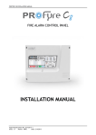
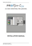
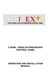
INFINITY 8 INSTALLATION MANUAL FIRE ALARM CONTROL PANEL INSTALLATION MANUAL Approved Document No. GLT-201-7-1 Issue: 1.6 Author: NRPJ Date: 27/7/2012 INFINITY 8 INSTALLATION MANUAL CONTENTS 1. INTRODUCTION............................................................................................................................................................................. 1.1 HANDLING THE PCBS................................................................................................................................................... 1.2 USING THIS MANUAL................................................................................................................................................... 1.3 ABOUT THE INFINITY FIRE ALARM CONTROL PANEL & INTEGRAL PSE........................................................................ 1.4 DESIGNING THE SYSTEM.............................................................................................................................................. 1.5 EQUIPMENT GUARANTEE............................................................................................................................................ 1.6 DEFINITION OF ACCESS LEVELS ON THE INFINITY PANEL............................................................................................. 1.7 FUNCTIONS REQUIRED BY EUROPEAN STANDARD EN 54 PART 2................................................................................ 2. FIRST FIX........................................................................................................................................................................................ 2.1 RECOMMENDED CABLE TYPES AND THEIR LIMITATIONS............................................................................................. 2.2 MAINS WIRING RECOMMENDATIONS......................................................................................................................... 2.3 DETECTOR CIRCUIT WIRING DIAGRAM........................................................................................................................ 2.4 SOUNDER CIRCUIT WIRING DIAGRAM......................................................................................................................... 2.5 AUXILIARY OUTPUT WIRING (VOLTAGE FREE CHANGEOVER CONTACTS).................................................................... 2.6 EXTRA RELAYS.............................................................................................................................................................. 3. MOUNTING THE FIRE ALARM PANEL............................................................................................................................................. 3.1 PLANNING CABLE ENTRY.............................................................................................................................................. 3.2 FIXING THE BACK BOX TO THE WALL........................................................................................................................... 4. CONNECTING MAINS & BATTERY POWER..................................................................................................................................... 4.1 CONNECTING THE MAINS POWER............................................................................................................................... 4.2 CONNECTING THE BATTERIES...................................................................................................................................... 5. FIELD DEVICE TERMINATION......................................................................................................................................................... 5.1 TERMINATING THE DETECTION AND ALARM (SOUNDER) CIRCUITS............................................................................ 5.2 AUXILIARY OUTPUT TERMINATIONS............................................................................................................................ 6. SOUNDER ACTIVATION DELAY........................................................................................................................................................ 6.1 DECIDING TO USE A DELAY........................................................................................................................................... 6.2 TO SET A DELAY............................................................................................................................................................ 6.3 WIRING CONSIDERATIONS WHEN USING A DELAY....................................................................................................... 6.4 DELAY INDICATION AND OVERRIDE............................................................................................................................. 7. ZONE DISABLEMENT...................................................................................................................................................................... 7.1 WHY USE ZONE DISABLEMENT.................................................................................................................................... 7.2 TO PROGRAMME ZONE (OR SOUNDERS) AS DISABLED............................................................................................... 7.3 IDENTIFYING DISABLED ZONES ON A PANEL SHOWING MULTIPLE EVENTS................................................................ 8. ZONE TEST..................................................................................................................................................................................... 8.1 WHY USE ZONE TEST.................................................................................................................................................... 8.2 TO PROGRAMME ZONE IN TEST................................................................................................................................... 8.3 IDENTIFYING ZONES IN TEST MODE ON A PANEL SHOWING MULTIPLE EVENTS......................................................... 9. GENERAL FAULT FINDING.............................................................................................................................................................. 9.1 ZONE FAULTS…............................................................................................................................................................. 9.2 SYSTEM FAULT.............................................................................................................................................................. 9.3 SUPPLY FAULTS............................................................................................................................................................. 9.4 EARTH FAULTS.............................................................................................................................................................. 9.5 SOUNDER FAULTS........................................................................................................................................................ 10. STANDBY BATTERY CALCULATION................................................................................................................................................ 11. PCB TERMINATION CONNECTIONS.............................................................................................................................................. 11.1 CONNECTIONS........................................................................................................................................................... 11.2 FUSES......................................................................................................................................................................... 12. PANEL SPECIFICATIONS................................................................................................................................................................ 12.1 ENCLOSURE SPECIFICATIONS..................................................................................................................................... 12.2 ELECTRICAL SPECIFICATIONS...................................................................................................................................... 13. ENGINEER OPTIONS (8 WAY CONFIG DIP SWITCH)...................................................................................................................... Approved Document No. GLT-201-7-1 Issue: 1.6 Author: NRPJ Date: 27/7/2012 2 2 2 2 2 3 3 3 4 4 4 4 5 5 5 7 7 7 8 8 8 9 9 9 10 10 10 10 10 12 12 12 12 13 13 13 13 14 14 14 14 15 15 15 16 16 17 17 17 17 18 PAGE 1 INFINITY 8 INSTALLATION MANUAL 1. INTRODUCTION THIS FIRE ALARM CONTROL PANEL IS CLASS 1 EQUIPMENT AND MUST BE EARTHED. This equipment must be installed and maintained by a qualified and technically experienced person. 1.1 HANDLING THE PCBS If the PCBs are to be removed to ease fitting the enclosure and cables, care must be taken to avoid damage by static. The best method is to wear an earth strap, but touching any earth point (e.g. building plumbing) will help to discharge any static. Hold PCBs by their sides, avoiding contact with any components. Always handle PCBs by their sides and avoid touching the legs of any components. Keep the PCBs away from damp dirty areas, e.g. in a small cardboard box. 1.2 USING THIS MANUAL This manual explains, in a step-by-step manner, the procedure for the installation of the Infinity 8 Range of Fire Alarm Control Panels. For full operational and maintenance information, please refer to document GLT.MAN- (USER MANUAL, MAINTENANCE GUIDE & LOG BOOK). It also contains a System set-up table, and Installation Certificate, that must be completed by the Commissioning Engineer prior to system handover. Unlike the User Manual, this Installation Manual must not be left accessible to the User. 1.3 ABOUT THE INFINITY FIRE ALARM CONTROL PANEL & INTEGRAL PSE The Infinity Fire alarm control panel is available in 1,2,4,6 or 8 Zone sizes. The 1 & 2 zone panels have 2 x 250mA sounder circuits. The 4, 6 & 8 zone panels have 4 x 150mA sounder circuits. It has a set of fire relay contacts (voltage free) rated at 1A SELV. It has a set of fault relay contacts (voltage free) rated at 1A SELV. This relay is normally powered to allow a fault output in the case of total power failure. It has the ability to disable any zone or the sounder circuits. It has a one man test mode, which resets the Zone in test after 5 seconds (EN54 option with requirements). It has a sounder delay facility (0-10 minutes in 1 minute steps)(EN54 option with requirements). It has a maximum battery capacity of 3.4Ah. It has an in built capability of operating with Diode bases (for line continuity on head removal). It will operate in ambient temperatures of -5 to 40°C. It will operate in a relative humidity of up to 93% (non-condensing). It will withstand vibrations between 5 & 150 Hz. It has a maximum capacity of 32 devices per zone. The PSE is a 35W Switch Mode cage with a nominal output of 30V. The battery is fused at 2A (quick blow). The PSE will draw a maximum of 30uA from the battery in the event of mains failure (the FACP will continue to take around 60mA). The FACP & PSE should be maintained as described in section 3 of the User Manual, Maintenance Guide & Log Book. 1.4 DESIGNING THE SYSTEM This manual is not designed to teach Fire Alarm System design. It is assumed that the installer has an understanding of Fire Alarm System components and their use. We strongly recommend consultation with a suitably qualified, competent person regarding the design of the Fire Alarm System. The System must be commissioned and serviced in accordance with our instructions and the relevant National Standards. Contact the Fire Officer concerned with the property at an early stage in case he has any special requirements. If in doubt, read BS 5839: Pt 1: 2002 “Fire Detection and Fire Alarm Systems for buildings (Code of Practice for System Design, Installation, Commissioning and Maintenance)” available from the BSI, or at your local reference library. 1.5 EQUIPMENT GUARANTEE If this equipment is not fitted and commissioned according to our guidelines, and the relevant National Standards, by an approved and competent person or organisation, the warranty may become void. Approved Document No. GLT-201-7-1 Issue: 1.6 Author: NRPJ Date: 27/7/2012 PAGE 2 INFINITY 8 INSTALLATION MANUAL 1.6 DEFINITION OF ACCESS LEVELS ON THE INFINITY PANEL ACCESS LEVEL ACCESSED BY ACCESS METHOD FUNCTIONS ACCESSED 1 General public Default state View panel Override delay (if used) LED test 2 Responsible person Access code entered Start/stop sounders Silence buzzer Reset panel Enable/disable sections of system Test mode 3a Installer/Engineer Access code entered & Installer password Set sounder delay time 3b Installer/Engineer Open enclosure Connect wiring during install Battery check during Maintenance Set configuration switches 4 Authorised Service Engineer Open enclosure & PC programming software Update panel firmware 1.7 FUNCTIONS REQUIRED BY EUROPEAN STANDARD EN 54 PART 2 The Premier Quatro fire alarm control panel provides the following mandatory and optional functions as prescribed by the European standard EN 54 Part 2. (a) Mandatory Functions The mandatory functions and corresponding indications provided by this panel are: fire alarm fault warning disabled, quiescent (b) Optional Functions The options with requirements provided by this panel are: output to fire alarm devices (i.e. sounders) delays to outputs Test Mode Approved Document No. GLT-201-7-1 Issue: 1.6 Author: NRPJ Date: 27/7/2012 PAGE 3 INFINITY 8 INSTALLATION MANUAL 2. FIRST FIX All wiring must be installed to meet BS5839: Pt1: 2002 and BS 7671 (Wiring Regs) standards. Other National standards of fire alarm system installation should be adhered to where applicable. 2.1 RECOMMENDED CABLE TYPES AND THEIR LIMITATIONS Screened cables should be used throughout the installation to help shield the Panel from outside interference and ensure EMC compatibility. The two categories of cable according to BS5839: Pt1: 2002, Clause 26 “Fire Detection and Alarm Systems for Buildings (Code of Practice for System Design, Installation and Servicing)” are: Standard fire resisting cable – to PH30 classification of EN 50200 Enhanced fire resisting cable – to PH120 classification of EN 50200 (Note that all cables should be at least 1mm2 cross section On the Infinity Panel the general recommendation would be to use standard fire resistant cable, such as Fire Defence, Firetuff™ , FP200 or an equivalent. These cables are screened, and will provide good ECM shielding when properly grounded at the panel. Certain system specifications may demand the use of a particular type of cable and due regard should be paid to this fact. Depending on the environment, the cables may need mechanical protection (such as a conduit). 2.2 MAINS WIRING RECOMMENDATIONS The Mains supply to the FACP is fixed wiring, using Fire resisting 3-core cable (Between 1 mm² and 2.5mm²) or a suitable 3conductor system, fed from an isolating double pole switch fused spur, fused at 3A. This should be secure from unauthorised operation and be marked ‘FIRE ALARM: DO NOT SWITCH OFF’. The supply must be exclusive to the Fire Panel. For information on how to connect Mains to the Panel’s Power Supply PCB, see page 8. Also refer to rating information inside the FACP. 2.3 DETECTOR CIRCUIT WIRING DIAGRAM The Infinity comes with one, two, four, six or eight Detection circuits (Zones). A maximum of 32 devices (i.e. smoke detectors, heat detectors, or Manual Call Points) can be fitted to each circuit. ALL DEVICES MUST BE POLARISED. Typical detector circuit wiring: An End of Line diode (provided in the Panel) must be connected across the terminals of the last device on each circuit to allow the wiring to be monitored. It is polarity sensitive, and connected cathode (STRIPE) to +ve Using detector bases with continuity diodes fitted will allow all devices, including Manual Call Points to remain operational if a detector is removed from its base. Old Manual call points, which just cause a short circuit, are not directly compatible, as they would cause a short circuit fault. Fitting a 470R resistor in line with the call point will allow it to work. (Wired in a similar way to non-polarised bells shown at the foot of this Approved Document No. GLT-201-7-1 Issue: 1.6 Author: NRPJ Date: 27/7/2012 PAGE 4 INFINITY 8 INSTALLATION MANUAL page). Other makes of detector will have different connections, but in general they are wired +IN & +OUT to same terminal, -IN to stripe side of continuity diode, -OUT to non-stripe side of continuity diode. Some makes will connect the +ve to a 470R load resistor, or a polarisation diode, to enable the detector to work correctly. If detectors other than Fyreye MK II are used the panel may need to be put into compatibility mode (See section 13) For more specific device wiring information, please refer to the manufacturers’ own instructions. The termination of each detection circuit must be as indicated on the main PCB (See page 15). The Earthing of the cable screens should be as shown on page 9. 2.4 SOUNDER CIRCUIT WIRING DIAGRAM Note: If non-polarised alarm devices (e.g. some types of old mechanical bell, or a relay) are used, then a diode will have to be placed in line with the device to enable fault monitoring. They may also need a back EMF protection diode. 2.5 AUXILIARY OUTPUT WIRING (VOLTAGE FREE CHANGEOVER CONTACTS) Auxiliary Fire Output (AUX): Changes over in any fire condition, and be used for driving local fire fighting equipment such as sprinkler systems, magnetic door holders, air conditioning shut off, etc. Fault Output (FAULT): This Output is energised in the quiescent condition. In a fault condition, the output relay turns off, to ensure fail-safe operation even in the event of total power loss. That is, the normally open contact will be closed when there is no fault, and open when there is a fault. This should be taken into account when any device is connected to the fault relay. 2.6 EXTRA RELAYS EN54-2 requires a fire panel to have a fault output. However, if the fault output is not being used, the infinity panel has the option to configure the fault relay as a second fire relay. See Engineering options (Section 13). Typical auxiliary output wiring: Approved Document No. GLT-201-7-1 Issue: 1.6 Author: NRPJ Date: 27/7/2012 PAGE 5 INFINITY 8 INSTALLATION MANUAL The termination for the above inputs must be as indicated on the main PCB (See page 15). The Earthing of the cable screens should be as shown on page 9. Approved Document No. GLT-201-7-1 Issue: 1.6 Author: NRPJ Date: 27/7/2012 PAGE 6 INFINITY 8 INSTALLATION MANUAL 3. MOUNTING THE FIRE ALARM PANEL It is recommended that the panel’s door be removed to avoid accidental damage. Also, the termination PCB could be removed and stored in a safe place, while fixing the back box to the wall. 3.1 PLANNING CABLE ENTRY Fig.2 below shows the location of the cable entries to facilitate planning of wiring (home runs) to be brought to the panel. The grommets can be easily removed by a push from inside the control panel box. If a grommet is removed, fill the hole with a brass cable gland. If any knockout is removed, but subsequently not used, it should be covered up. The 230Va.c. Mains cable must be fed into the enclosure via one of the cable entries at the top right corner of the back box. (Refer to “Connecting the Mains” on Page 8). 3.2 FIXING THE BACK BOX TO THE WALL Figure 2: Plan view inside the enclosure without PCBs. Side view for surface / flush installation. Fix the enclosure to the wall using the mounting holes provided. Check the build & condition of the wall to decide a suitable screw fixing. The mounting holes are designed for No 8 roundhead or countersunk woodscrews (or similar). Remove any debris from the enclosure. Take care not to damage the FACP during installation. Approved Document No. GLT-201-7-1 Issue: 1.6 Author: NRPJ Date: 27/7/2012 PAGE 7 INFINITY 8 INSTALLATION MANUAL 4. CONNECTING MAINS & BATTERY POWER 4.1 CONNECTING THE MAINS POWER Figure 3: Power Supply PCB layout and Mains connection details Figure 3 4.2 CONNECTING THE BATTERIES Figure 4: Battery location and connection details CAUTION: RISK OF EXPLOSION IF BATTERY IS REPLACED BY AN INCORRECT TYPE. DISPOSE OF USED BATTERIES ACCORDING TO BATTERY MANUFACTURERS INSTRUCTIONS Figure 4 Approved Document No. GLT-201-7-1 Issue: 1.6 Author: NRPJ Date: 27/7/2012 PAGE 8 INFINITY 8 INSTALLATION MANUAL 5. FIELD DEVICE TERMINATION 5.1 TERMINATING THE DETECTION AND ALARM (SOUNDER) CIRCUITS All cables entering the enclosure should use cable glands. The Detector and Sounder circuits should be connected to the appropriate connector block on the Termination PCB as shown in Figure 6 below. All screens should be fed through the gland to make electrical contact with it, and be terminated at the brass earthing strip as shown below (see Figure 6) (For detailed detector and alarm circuit wiring diagrams, please refer to pages 6 and 7.) 5.2 AUXILIARY OUTPUT TERMINATIONS Connect auxiliary output cables to the appropriate connector block terminals on the Termination PCB (See Page 15). Screened cables should be terminated as per figure 6. For a full description of the inputs and outputs available on the Infinity range of Fire Panels, including typical wiring diagrams please refer to pages 6 & 7. Approved Document No. GLT-201-7-1 Issue: 1.6 Author: NRPJ Date: 27/7/2012 PAGE 9 INFINITY 8 INSTALLATION MANUAL 6. SOUNDER ACTIVATION DELAY 6.1 DECIDING TO USE A DELAY A delay of up to ten minutes from the Fire Alarm Panel being triggered, to its Alarm sounder outputs being activated, can be programmed into the panel by the Engineer. This is a particularly useful feature for schools, nightclubs and other public places where the nuisance and panic caused by a false alarm must be avoided. It should be noted that the delay period will apply to ALL DETECTOR zones. Call point Zones will not be delayed. When a sounder delay is used, zone 1 is designated as a call point zone, and an alarm in this zone will not be delayed. There is an option to define the last zone as a call point zone also (see section 13: Engineer Options). All other zones will be designated as detector zones. When an Alarm occurs on any detector zone, it is processed as normal. However, the activation of the sounders is postponed until the delay period has expired, thus allowing the cause of the Alarm to be investigated by the User. If the alarm is false the alarm can be cancelled. 6.2 TO SET A DELAY 1. Enter the access code (default 1245) and press 2. Enter access level 3 (1246) and press 3. Hold 4. Type in the number of minutes you require the delay to be: . . for 3 seconds. 1-8 minutes type the number with the keypad. 0 minutes type nothing. 9 minutes type 81. 10 minutes type 82. Press . 5. The panel will flash a confirmation of the selected delay. 6. Press 3 times to exit access level 3. 6.3 WIRING CONSIDERATIONS WHEN USING A DELAY A delay is not usually applied to manual call points, unless there are exceptional circumstances to be taken into consideration. In order to meet this requirement, call points should be connected to a zone that is not delayed. On the infinity panel, zone 1 is never delayed, so call points should be connected to zone 1. If more than one 'call point zone' is needed, the last zone on the panel can also be set as non-delayed by setting configuration dip switch 8 to the on position. 6.4 DELAY INDICATION AND OVERRIDE If a delay is set, the fire panel will light the Delay (SOUNDER DELAY) LED to indicate that the sounders are delayed. If an alarm occurs, the fire LEDs will light as usual, but the sounders will not start until the delay period has expired. After the delay period, the Delay LED will extinguish & the sounders will start. Pressing the switch will override the delay at any time and results in the sounders being turned on immediately. If on investigation, the panel was activated by a false alarm, enter the access code to enable the Controls, and press the reset button. This will return the system to normal, without the sounders being activated. (Assuming the cause of the false alarm has been removed). The delay can be toggled on/off: 1. Enter access code (1245) press . 2. Press . 3. Press again to deactivate sounder delay. Approved Document No. GLT-201-7-1 Issue: 1.6 Author: NRPJ Date: 27/7/2012 PAGE 10 INFINITY 8 INSTALLATION MANUAL 7. ZONE DISABLEMENT 7.1 WHY USE ZONE DISABLEMENT To aid commissioning and assist routine maintenance checks, any of the zones or the sounder circuits can be disabled. When a zone (or sounder cct) is disabled, the panel will not respond to any fault or fire signals it receives from that zone. This might be used if the system requires routine maintenance, and the customer needs the system to continue running, but doesn’t want spurious false alarms. The panel will respond in the usual manner to any events in any non-disabled zones. 7.2 TO PROGRAMME ZONE (OR SOUNDERS) AS DISABLED Any number of zones (or the sounders) can be disabled, but it is good practice to only disable one zone at a time. 1. Enter access code (default 1245) and press 2. Press 3. Type the number of the zone you want to disable. If you wish to disable the sounders press 4. Press 5. To leave disable mode hold the 6. The Zone and Disable LED’s will be lit to show the disablement. 7. To re-enable the zone enter the access (1245) press 8. Press and hold 9. Type the zone number again and press Press and hold . for 3 seconds. . to disable the selected zone or sounders. button for 3 seconds. . for 3 seconds. . for 3 seconds, Zone is now re-enabled. 7.3 IDENTIFYING DISABLED ZONES ON A PANEL SHOWING MULTIPLE EVENTS On the infinity panel, Zones or sounder disablements are indicated by a steady GENERAL DISABLEMENT LED, along with a specific Disablement LED. But to allow the user to be 100% certain of the disablements if the panel is showing multiple events, momentarily pressing the button at Access Level 2 will hide all other events for a few seconds, leaving only the Disablements visible Approved Document No. GLT-201-7-1 Issue: 1.6 Author: NRPJ Date: 27/7/2012 PAGE 11 INFINITY 8 INSTALLATION MANUAL 8. ZONE TEST 8.1 WHY USE ZONE TEST To aid commissioning and assist routine maintenance check, a non-latching ‘one man test’ facility is available. When a detector or manual call point is triggered on any zone in Test, the Alarm sounders operate for approximately five seconds on and seven seconds off. This cycle continues until the cause of the Alarm is removed (either by the test smoke clearing from the detector or the manual call point being reset), at which point, the detector circuit also automatically resets. Should an Alarm occur on a zone that is not programmed to test, the Alarm will be processed in the normal way. The testing of the zone in test will temporarily be suspended until the Alarm(s) from the other zones are reset. At this point, zone retesting may resume. 8.2 TO PROGRAMME ZONE IN TEST NOTE: Only one zone can be programmed in test at any one time. 1. Enter access code (1245) press 2. Press and hold 3. Select the zone you wish to put into test mode by typing the number with the keypad. The Zone & test LEDs will be flashing with a pattern 4 flashes then a pause (repeated). The zone is not in test mode at this point. 4. Press to start test mode. The Zone & test LEDs will be flashing with a pattern 12 flashes then a pause (repeated). The zone is now in test mode. 5. To set a different zone into test mode, press the zone number, followed by the original zone returns to normal operation. To end test mode press . for 3 seconds. . The new zone is now in test mode, and for 3 seconds. For safety reasons, it is not possible to leave a zone in test while performing other maintenance functions (Such as disablement). This stops the possibility of leaving a section in test mode while another part of the system is being investigated. Trying to select disablement mode while test mode is active will result in the panel giving a warning tone, and a reminder that the panel is in test mode. Test mode must then be exited (By pressing accessed. for 3 seconds) before disablement mode can be If a panel does need both disablements & test mode to be applied at the same time, the disablement should be performed first. 8.3 IDENTIFYING ZONES IN TEST MODE ON A PANEL SHOWING MULTIPLE EVENTS On the infinity panel, a Zone in test is indicated by a fast flashing GENERAL TEST LED, along with a specific zone test LED. But to allow the user to be 100% certain of any zones in test mode if the panel is showing multiple events, momentarily pressing the button at Access Level 2 will hide all other events for a few seconds, leaving only the Zone in test visible. Approved Document No. GLT-201-7-1 Issue: 1.6 Author: NRPJ Date: 27/7/2012 PAGE 12 INFINITY 8 INSTALLATION MANUAL 9. GENERAL FAULT FINDING 9.1 ZONE FAULTS To assist in fault finding, the infinity panel will display zone faults as follows. The general fault LED will flash if a fault is present. On the first flash, any zones showing O/C will flash. The second time the General fault LED flashes, any zones with a Short Circuit fault will flash in conjunction with the General S/C LED. The cycle then repeats, showing O/C & S/C faults on alternate flashes. (The internal fault buzzer will also sound, and the fault relay will operate) The Zone Faults are non-latching faults. That is, if the fault disappears, the panel will automatically reset itself. Suggested Action a) Disconnect the wiring for the zone showing fault, and refit the end of line diode at that zone terminal in the panel. (Stripe to Zone +ve) If the fault condition for that zone clears, this confirms there is a wiring fault. b) Double-check the wiring and the end of line diode on the zone. Trace the fault with consideration for the type of fault indicated.(HINT: splitting the cable half way down the zone, and fitting the end of line diode to the new end point helps to determine which section of cable is giving the fault) Note: A possible fault is a detector head badly seated in a base that is not making the connection. c) A short circuit on a zone could be caused by the end of line diode being fitted backwards. d) Check that the detectors are compatible with this FACP. Note that some makes of detector will require a series resistor or diode to be fitted to work properly. There is usually a spare connector on the base to accommodate this (check instructions that came with the detector). 9.2 SYSTEM FAULT A system fault is an abnormal microprocessor running condition due to various unexpected phenomena This will result in the panel attempting to correct itself. Should this fault occur, the System Fault LED, General Fault LED, General Fault relay and fault internal buzzer will be constantly active To reset a system fault, enter the access code, and press reset. If the system fault does not clear, the panel has been damaged, and will need to be repaired or replaced. 9.3 SUPPLY FAULTS The Infinity panel indicates supply faults with one long flash, followed by a number of shorter flashes. The number of short flashes indicates the type of fault:1 FLASH Mains Fault or Cage Fault 2 FLASHES Battery not present 3 FLASHES Battery voltage too low 4 FLASHES Battery internal resistance too high 5 FLASHES Charger fault 1 Flash - Mains Fault or Cage fault a. Check that main power is present. b. Check that cage voltage is set to 30.5 V DC 2 Flashes - Battery not present a. Check that 2 x 12V SLA batteries are fitted b. Check battery fuse FS6. c. Check that battery connections are secure. 3 Flashes - Battery voltage too low. Approved Document No. GLT-201-7-1 Issue: 1.6 Author: NRPJ Date: 27/7/2012 PAGE 13 INFINITY 8 INSTALLATION MANUAL a. The batteries have reached their final voltage. If the panel is not charging them, they will need to be replaced. 4 Flashes - Battery internal resistance too high a. The batteries have a high internal resistance, and will need to be replaced. 5 Flashes - Charger fault a. Check that the charger disable link J2 has not been removed b. If (a) is OK, then the charger circuit on the PCB has been damaged, and the PCB will need to be repaired or replaced 9.4 EARTH FAULTS An EARTH fault indicates that something is shorting to earth (usually through the cable screen). Disconnect the earth screens one at a time to determine the problem line. (Note: connecting other equipment , e.g. an oscilloscope , to the panel can give an earth fault) 9.5 SOUNDER FAULTS Similar to the zone faults, the infinity panel will display sounder faults as either O/C or S/C (in conjunction with the gen S/C LED). The infinity panel monitors each circuit separately, so it is possible that one circuit has an O/C fault, and another circuit has a S/C fault. To track down the problem:Check that the correct END of Line resistor has been fitted. (10K – brown, black, orange, gold) If working on an existing installation, check that the devices are polarised. (See Page 5) Check cable continuity (remove from panel and measure continuity. Should read 10K The Infinity 8 panel uses resettable fuses, which 'open' in the event of a fault, and reset when the fault clears. They do not need replacing. Approved Document No. GLT-201-7-1 Issue: 1.6 Author: NRPJ Date: 27/7/2012 PAGE 14 INFINITY 8 INSTALLATION MANUAL 10. STANDBY BATTERY CALCULATION In order to calculate the standby battery size required, the following formula can be used:Battery Size (Standby time in Amp Hours) = 1.25 x [(TALM x IALM) + (TSBY x (IQP + IQZ))] Where: TALM = Maximum time in hours required for the alarm [½ hour is most common time] IALM = Total Alarm Current in amps for all alarm devices connected to the alarm circuits TSBY = Standby time in hours for the system after mains failure [normally 24, 48 or 72 hr] IQP = Quiescent current in amps of control panel in fault condition [because of mains failure] IQZ = Quiescent current in amps of all detection zones. E.g. Ion detector 0.00005 Amp (50 μA) , Optical Detector = 0.0001 Amp (100 μA) Typical Example: A system comprises of 20 ionisation detectors, 14 bells and the required standby is 24 hours. It will need to operate in alarm for ½ hour. Calculate the battery size required. TALM = 0.5 Hr IALM = 14 x 0.025 =0.35A [This assumes the bell current is 25 mA. Most alarm Devices show their operating current] TSBY = 24 Hr IQP = 0.085A IQZ = 20 x 0.00005 =0.001A [the quiescent current for an ionisation detector is 50 μA] Therefore using the equation: Battery Size (Standby time in Amp Hours) = 1.25 x [(TALM x IALM) + (TSBY x (IQP + IQZ))] Battery Size (Standby time in Amp Hours) = 1.25 x [(0.5 x 0.35) + (24 x (0.048 + 0.001))] Battery Size (Standby time in Amp Hours) = 1.25 x [0.175 + (24 x 0.049)] Battery Size (Standby time in Amp Hours) = 1.25 x [0.175 + 1.176] Battery Size (Standby time in Amp Hours) = 1.25 x 1.351 Battery Size (Standby time in Amp Hours) = 1.69 Amp Hours This system would require a minimum of 1.69Ah batteries. Approved Document No. GLT-201-7-1 Issue: 1.6 Author: NRPJ Date: 27/7/2012 PAGE 15 INFINITY 8 INSTALLATION MANUAL 11. PCB TERMINATION CONNECTIONS 11.1 CONNECTIONS CONNECTION NO. DESCRIPTION USE 1 ZONE 1 +&- Connect to Zone 1 2 ZONE 2 +&- Connect to Zone 2 3 ZONE 3 +&- Connect to Zone 3 4 ZONE 4 +&- Connect to Zone 4 5 ZONE 5 +&- Connect to Zone 5 6 ZONE 6 +&- Connect to Zone 6 7 ZONE 7 +&- Connect to Zone 7 8 ZONE 8 +&- Connect to Zone 8 9 SND 1 +&- Connect to sounder circuit 1 (sirens/bells) 10 SND 2 +&- Connect to sounder circuit 2 (sirens/bells) 11 SND 3 +&- Connect to sounder circuit 3 (sirens/bells) 12 SND 4 +&- Connect to sounder circuit 4 (sirens/bells) 13 FAULT RELAY NC/CM/NO Normally powered i.e. NO is closed with no fault 14 FIRE RELAY NO/CM/NC Normally open, Activates on Fire condition 15 24V DC IN CONNECTION FROM CAGE 16 BATTERY +&- STANDBY BATTERY TERMINALS 17 RS485 COMMS FOR REPEATER (FUTURE) DESCRIPTION RATING FS2 Sounder circuit 1 150mA thermal fuse FS3 Sounder circuit 2 150mA thermal fuse FS4 Sounder circuit 3 150mA thermal fuse FS5 Sounder circuit 4 150mA thermal fuse FS6 Battery Fuse 2A quick 5 x 20mm glass 11.2 FUSES FUSE NO. Approved Document No. GLT-201-7-1 Issue: 1.6 Author: NRPJ Date: 27/7/2012 PAGE 16 INFINITY 8 INSTALLATION MANUAL 12. PANEL SPECIFICATIONS 12.1 ENCLOSURE SPECIFICATIONS DESCRIPTION VALUE ENCLOSURE SIZE 364 X 302 X 90 mm TOP CABLE ENTRIES 15 x 20 mm DIA knock outs 12.2 ELECTRICAL SPECIFICATIONS ELECTRICAL DESCRIPTION VALUE MAINS VOLTAGE 100-240V AC +/-10% @ 50/60 Hz BATTERY VOLTAGE 24V DC (2 X 12V SLA BATTERY) SYSTEM VOLTAGE 24V DC NOMINAL (18 – 32 V) SYSTEM VOLTAGE RIPPLE 2V PK-PK MAX CHARGER SIZE UP TO 3.4AH in 24 Hours ZONE VOLTAGE 22.5V DC NOMINAL SOUNDER ALARM OUTPUTS 2 x 150mA @ 24V DC (1 & 2 zone panel) 4 x 150mA @ 24V DC (4, 6, & 8 zone panel) AUXILIARY FAULT OUTPUT 1 x RELAY SELV (1A MAX) AUXILIARY FIRE OUTPUT 1 x RELAY SELV (1A MAX) NUMBER OF ZONES 1/2/4/6/8 MAXIMUM ZONE CAPACITY 32 DEVICES PER ZONE SOUNDER ACTIVATION DELAY 0-10 MINUTES - IN 1 MIN INCREMENTS ZONE END OF LINE DEVICE 1N4002 DIODE (CATHODE STRIPE TO +) SOUNDER END OF LINE DEVICE 10 K RESISTOR CHARGER VOLTAGE 28.6V @ 25 C (NO BATTERY CONNECTED) ZONE SHORT CIRCUIT PROTECTION 40mA CHARGER SHORT CIRCUIT PROTECTION Batteries less than 20V TOTAL CHARGER OUTPUT 1.15 Amp o MAX CURRENT DRAIN FROM BATTERY (DURING MAINS FAILURE) 1.0 Amp WHEN PSE LOAD IS I MAX A I MAX A 1 Amp I MAX B 1 Amp RI MAX 2.8 Ω Approved Document No. GLT-201-7-1 Issue: 1.6 Author: NRPJ Date: 27/7/2012 PAGE 17 INFINITY 8 INSTALLATION MANUAL 13. ENGINEER OPTIONS (8 WAY CONFIG DIP SWITCH) The Infinity FCP has the following configuration options: Switch 1 ON = Compatibility Mode – use if Fyreye II Detectors are NOT used Switch 2 ON = Zone 2 non latching Switch 3 ON = Sounder circuit 3 active giving a power output Switch 4 ON = Sounder circuit 4 active giving a power output Switch 5 ON = DUTCH MARKET ONLY Switch 6 ON = Fault relay activates on a fire condition (Giving 2 fire relays) Switch 8 ON = Makes the last zone on the panel a call point zone (alarms from that zone not delayed) Note: The above options my not comply with local regulations. Please check with the relevant codes of practice in your region. 0086 Zeta Alarm Systems by GLT Exports Ltd, 72-78 Morfa Road, Swansea SA1 2EN 12 0086-CPD-575041 EN54-2:1997+A1:2002 + A2: 2006 EN54-4:1997+A1:2002 + A2: 2006 Control and indicating equipment for fire detection and fire alarm systems for buildings Infinity Conventional Fire Panel IN1, IN2, IN4, IN6, IN8 Provided options: Output to fire alarm devices Delays to outputs Test Condition Other Technical Data: See Doc: “Infinity 8 Product file” held by the manufacturer Approved Document No. GLT-201-7-1 Issue: 1.6 Author: NRPJ Date: 27/7/2012 PAGE 18