1
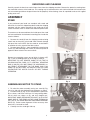
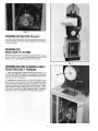
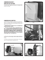
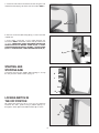
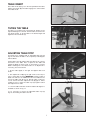
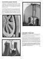
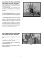
(Model 28-280)
The Serial No./Model No. plate is attached to the
right side of the base casting. Locate this plate and
record the Serial No. and Model No. in your manual
for future reference.
SERIAL NO.___________________________________
MODEL NO. __________________________________
DATED 1-15-96
PART NO. 426-02-651-0023
©Delta International Machinery Corp. 1996
INSTRUCTION MANUAL
14"
Wood Cutting
Band Saw
SAFETY RULES
Woodworking can be dangerous if safe and proper operating procedures are not followed. As with all machinery, there are certain hazards involved
with the operation of the product. Using the machine with respect and caution will considerably lessen the possibility of personal injury. However, if
normal safety precautions are overlooked or ignored, personal injury to the operator may result. Safety equipment such as guards, push sticks, holddowns, featherboards, goggles, dust masks and hearing protection can reduce your potential for injury. But even the best guard won’t make up for
poor judgment, carelessness or inattention. Always use common sense and exercise caution in the workshop. If a procedure feels dangerous, don’t
try it. Figure out an alternative procedure that feels safer. REMEMBER: Your personal safety is your responsibility.
This machine was designed for certain applications only. Delta Machinery strongly recommends that this machine not be modified and/or used for
any application other than that for which it was designed. If you have any questions relative to a particular application, DO NOT use the machine
until you have first contacted Delta to determine if it can or should be performed on the product.
DELTA INTERNATIONAL MACHINERY CORP.
MANAGER OF TECHNICAL SERVICES
246 ALPHA DRIVE
PITTSBURGH, PENNSYLVANIA 15238
(IN CANADA: 644 IMPERIAL ROAD, GUELPH, ONTARIO N1H 6M7)
WARNING: FAILURE TO FOLLOW THESE RULES
MAY RESULT IN SERIOUS PERSONAL INJURY
It’s safer than using your hand and frees both hands to operate tool.
1. FOR YOUR OWN SAFETY, READ INSTRUCTION MANUAL
BEFORE OPERATING THE TOOL. Learn the tool’s application and
limitations as well as the specific hazards peculiar to it.
15. DON’T OVERREACH. Keep proper footing and balance at all
times.
2. KEEP GUARDS IN PLACE and in working order.
16. MAINTAIN TOOLS IN TOP CONDITION. Keep tools sharp and
clean for best and safest performance. Follow instructions for lubricating and changing accessories.
3. ALWAYS WEAR EYE PROTECTION.
4. GROUND ALL TOOLS. If tool is equipped with three-prong plug,
it should be plugged into a three-hole electrical receptacle. If an
adapter is used to accommodate a two-prong receptacle, the adapter
lug must be attached to a known ground. Never remove the third
prong.
17. DISCONNECT TOOLS before servicing and when changing
accessories such as blades, bits, cutters, etc.
18. USE RECOMMENDED ACCESSORIES. The use of accessories
and attachments not recommended by Delta may cause hazards or
risk of injury to persons.
5. REMOVE ADJUSTING KEYS AND WRENCHES. Form habit of
checking to see that keys and adjusting wrenches are removed from tool
before turning it “on.”
19. REDUCE THE RISK OF UNINTENTIONAL STARTING. Make
sure switch is in “OFF” position before plugging in power cord.
6. KEEP WORK AREA CLEAN. Cluttered areas and benches invite
accidents.
20. NEVER STAND ON TOOL. Serious injury could occur if the tool is
tipped or if the cutting tool is accidentally contacted.
7. DON’T USE IN DANGEROUS ENVIRONMENT. Don’t use power
tools in damp or wet locations, or expose them to rain. Keep work area
well-lighted.
21. CHECK DAMAGED PARTS. Before further use of the tool, a
guard or other part that is damaged should be carefully checked to
ensure that it will operate properly and perform its intended function –
check for alignment of moving parts, binding of moving parts, breakage
of parts, mounting, and any other conditions that may affect its operation. A guard or other part that is damaged should be properly
repaired or replaced.
8. KEEP CHILDREN AND VISITORS AWAY. All children and visitors should be kept a safe distance from work area.
9. MAKE WORKSHOP CHILDPROOF – with padlocks, master
switches, or by removing starter keys.
22. DIRECTION OF FEED. Feed work into a blade or cutter against the
direction of rotation of the blade or cutter only.
10. DON’T FORCE TOOL. It will do the job better and be safer at the
rate for which it was designed.
23. NEVER LEAVE TOOL RUNNING UNATTENDED. TURN POWER
OFF. Don’t leave tool until it comes to a complete stop.
11. USE RIGHT TOOL. Don’t force tool or attachment to do a job for
which it was not designed.
12. WEAR PROPER APPAREL. No loose clothing, gloves, neckties,
rings, bracelets, or other jewelry to get caught in moving parts. Nonslip
footwear is recommended. Wear protective hair covering to contain
long hair.
24. DRUGS, ALCOHOL, MEDICATION. Do not operate tool while
under the influence of drugs, alcohol or any medication.
13. ALWAYS USE SAFETY GLASSES. Wear safety glasses. Everyday
eyeglasses only have impact resistant lenses; they are not safety
glasses. Also use face or dust mask if cutting operation is dusty.
26. WARNING: The dust generated by certain woods and wood products can be injurious to your health. Always operate machinery in well
ventilated areas and provide for proper dust removal. Use wood dust
collection systems whenever possible.
25. MAKE SURE TOOL IS DISCONNECTED FROM POWER SUPPLY
while motor is being mounted, connected or reconnected.
14. SECURE WORK. Use clamps or a vise to hold work when practical.
ADDITIONAL SAFETY RULES FOR BAND SAWS
1. ADJUST the upper guide about 1/8 above the material being cut.
2. MAKE SURE that blade tension and blade tracking are properly
adjusted.
3. STOP the machine before removing scrap pieces from the table.
4. ALWAYS keep hands and fingers away from blade.
5. CHECK for proper blade size and type.
6. DO NOT attempt to saw stock that does not have a flat surface,
unless a suitable support is used.
7. HOLD material firmly and feed into blade at a moderate speed.
8. TURN OFF machine if the material is to be backed out of an uncompleted cut.
9. MAKE “release” cuts before cutting long curves.
10. ADDITIONAL INFORMATION regarding the safe and proper
operation of this product is available from the National Safety Council,
1121 Spring Lake Drive, Itasca, IL 60143-3201 in the Accident
Prevention Manual for Industrial Operations and also in the Safety
Data Sheets provided by the NSC. Please also refer to the American
National Standards Institute ANSI 01.1 Safety Requirements for
Woodworking Machinery and the U.S. Department of Labor OSHA
1910.213 Regulations.
2
UNPACKING AND CLEANING
Carefully unpack the band saw and all loose items from the shipping container. Remove the protective coating from
the machined surfaces of the band saw. This coating may be removed with a soft cloth moistened with kerosene (do
not use acetone, gasoline or lacquer thinner for this purpose). After cleaning, cover all unpainted surfaces with a good
quality paste wax.
ASSEMBLY
STAND
If you purchased your band saw complete with stand and
electricals, the stand is shipped top down inside the shipping
container with the motor mounted to the inside top of the
stand. The on/off switch is wired to the end of the power cord.
The motor must be removed from the inside top of the stand
and reassembled to the horizontal mounting bars insede the
stand as follows:
1. Remove the stnad (A) from the shipping container being
careful not to crimp the switch cord which extends through
the top of the stand. NOTE: Set the stand on several blocks
of wood to raise the stand off the floor surface.
2. Remove paner (B) Fig. 1, from stgand (A) by removing two
screws (C) and loosening two screws (D). Remove panel on
opposite side of stand in the same manner.
Fig. 1
Remove two mounting screws, one of which is shown at (E)
Fig. 2, that are holding motor (F) to the top of stand (A).
IMPORTANT: DO NOT REMOVE CABLE TIE (G) THAT IS
HOLDING SWITCH CORD (H) TO VERTICAL MOUNTING
BAR (J) UNLESS YOU ARE USING THE ACCESSORY 28894 HEIGHT ATTACHMENT ON THE BAND SAW. THIS
CABLE TIE (G) WILL KEEP THE SWITCH CORD (H) FROM
CONTACTING THE MOTOR PULLEY OR BELT DURING
OPERATION.
Fig. 2
ASSEMBLING MOTOR TO STAND
1. To make the motor assembly easier, turn stand (A) Fig.
2A, on its side with two horizontal bars (B) down as shown.
2. Position motor (C) Fig. 2A, on two horizontal suport bars
(B) as shown, and fasten with four 3/4" long carriage bolts,
two of which are shown at (D), and four flanged nuts.
IMPORTANT: MAKE CERTAIN MOTOR SHAFT (e) IS ON THE
SAME SIDE OF THE STAND AS THE LARGE OPENING IN
THE TOP OF THE STAND BEFORE TIGHTENING CARRIAGE
BOLTS (D). Further motor alignment will be necessary after
band saw is fastened to stand.
3. Carefully turn the stand right side up.
Fig. 2A
3
4
ASSEMBLING BELT
AND PULLEY GUARD
Assemble the belt and pulley guard (A) to the top of the stand,
as shown in Fig. 6, using the two 1/4-20 x 1/2 hex head screws,
washers and nuts (B).
ASSEMBLING SWITCH
If you purchased your band saw complete with stand and electricals, you received a switch mounted in a switch box and a
cord set connected to the motor. Assemble the switch to the
band saw arm as follows:
Fig. 6
1. MAKE CERTAIN THE BAND SAW IS DISCONNECTED
FROM THE POWER SOURCE.
2. CAUTION: THE ON/OFF SWITCH-TO-MOTOR CORD (F)
FIG. 7, IS TIED TO VERTICAL MOUNTING POST (G) OPPOSITE THE MOTOR PULLEY. THIS CABLE TIE (H) PREVENTS
THE SWITCH-TO-MOTOR CORD (F), FROM CONTACTING THE BELT OR MOTOR PULLEY DURING OPERATION.
IMPORTANT: DO NOT REMOVE THIS CABLE TIE UNLESS
YOU ARE USING THE ACCESSORY #28-984 HEIGHT
ATTACHMENT WITH THE BAND SAW.
3. Remove two outer hex nuts and lock washers (A) Fig. 8,
from the two screws extending out from the back of the switch
box (B).
4. Insert two screws (C) Fig. 9, located on back of switch box,
into two holes (D) located in the band saw arm.
Fig. 7
B
A
D
C
F
Fig. 8
Fig. 9
5
5. Fasten the switch box to the band saw arm using two nuts
and lockwashers (A) Fig. 10, which were removed in STEP 3.
A
Fig. 10
6. Remove screw and cable clamp (E) Fig. 11, from lower arm
of band saw.
7. Insert switch cord (F) Fig. 12, into clamp (E) which was
removed in STEP 6, and fasten switch cord (F) to band saw
as shown. IMPORTANT: CHECK AND MAKE CERTAIN THE
ON/OFF SWITCH-TO-MOTOR CORD (F) FIG. 7, IS NOT
CONTACTING MOTOR PULLEY OR BELT. ADJUST CORD
(F) FIG. 7, IF NECESSARY, THEN TIGHTEN CABLE TIE (H).
E
Fig. 11
STARTING AND
STOPPING SAW
To start the saw, press the “START” button (K) Fig. 12. To stop
the saw, press the “STOP” button (L) Fig. 12.
K
L
F
E
Fig. 12
LOCKING SWITCH IN
THE OFF POSITION
We suggest that when the saw is not in use, the switch be
locked in the “OFF” position using a padlock (M) Fig. 13,
through the switch plate and “START” button (K) as shown.
K
M
Fig. 13
6
TABLE INSERT
Place table insert (A) Fig. 14, in the hole provided in the table,
making sure the pin (B) in the table engages one of the indents
in the table insert.
Fig. 14
TILTING THE TABLE
The table on your band saw can be tilted 45 degrees to the
right and 10 degrees to the left. To tilt the table, loosen the two
lock knobs (A) Fig. 15, tilt the table to the desired angle and
tighten the two lock knobs (A).
Fig. 15
ADJUSTING TABLE STOP
The band saw is equipped with an adjustable table stop (A)
Fig. 16, that allows the table to be set perfectly at 90 degrees
with the blade.
Tilt the table to the left until the table stop (A) Fig. 16, contacts
the bottom of the table. Place a square on the table and
against the blade as shown in Fig. 14, and check to see if the
blade is 90 degrees to the table surface. If an adjustment is
necessary, proceed as follows:
1. Tilt the table slightly to the right and tighten table lock
knobs.
2. Turn adjustment nut (B) Fig. 16, right or left as necessary to
raise or lower table stop (A). IMPORTANT: Certain models of
band saws will have an additional locknut assembled to the
end of the table stop (A) Fig. 16, directly under casting (C).
Loosen locknut and turn adjustment nut (B) right or left as
needed to raise or lower the table stop (A). Tighten locknut
after adjustment is made.
Fig. 16
3. Lower the table and make certain the table is 90 degrees to
the blade as shown in Fig. 17.
4. It is necessary to remove the adjustable table stop (A)
Fig. 16, when tilting the table to the left.
Fig. 17
7
ADJUSTING BLADE TENSION
On the back of the upper wheel slide bracket, there is a series
of graduations. These indicate the proper tension for various
widths of blades. With the blade on the wheels, turn the knob
(A) Fig. 18, to raise or lower the wheel, until the red fiber
washer (B) is in line with the proper graduation for the size of
blade being used.
The graduations will be found correct for average work, and
are not affected by rebrazing of the saw blade. We urge you to
use these graduations until you have become familiar enough
with the operation of the Band Saw to vary the tension for different kinds of blades or work. Over-straining is a common
cause of blade breakage and other unsatisfactory blade performance. Release the tension when the machine is not in use.
Fig. 18
TRACKING THE BLADE
IMPORTANT: Before tracking the blade, make sure the blade
guides and blade support bearings are clear of the blade so as
not to interfere with the tracking adjustment.
After tension has been applied to the blade, revolve the wheels
slowly forward by hand and watch the blade (A) Fig. 19, to see
that it travels in the center of the upper tire. If the blade begins
to creep toward the front edge, loosen the wing nut (B) Fig. 20,
and tighten the thumb screw (C). This will tilt the top of the
wheel toward the back of the machine and will draw the blade
toward the center of the tire. If the blade creeps toward the
back edge, turn the thumb screw in the opposite direction.
Adjust the thumb screw (C) Fig. 20, only a fraction of a turn at
a time. NEVER TRACK THE BLADE WHILE THE MACHINE
IS RUNNING. After the blade is tracking in the center of the
tires, tighten the wing nut (B) Fig. 20.
Fig. 19
Fig. 20
8
ADJUSTING UPPER BLADE
GUIDE ASSEMBLY
The upper blade guide assembly (A) Fig. 21, should always be
set as close as possible to the top surface of the material being
cut by loosening lock knob (B) and moving the guide assembly
(A) to the desired position.
Fig. 21
The upper blade guide assembly should also be adjusted so
that the blade guides (A) Fig. 22, are flat with the blade. If an
adjustment is necessary, loosen screw (B) and rotate the complete guide assembly (C) until the blade guides are flat with the
blade.
Fig. 22
9
ADJUSTING UPPER BLADE GUIDES
AND BLADE SUPPORT BEARING
The upper blade guides and blade support bearings are adjusted only after the blade is tensioned and tracking properly.
To adjust proceed as follows:
1. The upper blade guides (A) Fig. 23, are held in place by
means of the set screws (B). Loosen the set screws (B) to
move the guides (A) as close as possible to the side of the
blade, being careful not to pinch the blade. Then tighten the
screws (B).
2. The guides (A) Fig. 23, should then be adjusted so that the
front edge of the guides are just behind the “gullets” of the saw
teeth. The complete guide block bracket can be moved in or
out by loosening thumb screw (C) and turning knurled knob (D)
Fig. 23. When guides (A) are set properly, tighten thumb
screw (C).
Fig. 23
3. The upper blade support bearing (E) Fig. 23, prevents the
blade from being pushed too far to the back which could
damage the set in the saw teeth. The support bearing (E)
should be set 1/64 behind the blade by loosening thumb
screw (F) and turning knurled knob (G) to move the support
bearing (E) in or out.
4. The blade support bearing (E) should also be adjusted so
the back edge of the blade overlaps the outside diameter of
the ball bearing by about 1/16 . The bearing (E) is set on an
eccentric and to change position remove screw (H) and bearing (E) Fig. 23. Loosen thumb screw (F), back out screw (G)
and re-position shaft that bearing (E) is attached to.
ADJUSTING LOWER BLADE GUIDES
AND BLADE SUPPORT BEARING
The lower blade guides and blade support bearing should be
adjusted at the same time as the upper guides and bearing as
follows:
1. Loosen the two screws (A) Fig. 24, and move the guides (B)
as close as possible to the side of the blade, being careful not
to pinch the blade. Then tighten screws (A).
2. The front edge of the guide blocks (B) should be adjusted
so they are just behind the “gullets” of the saw teeth by turning the knurled knob (C) Fig. 24.
Fig. 24
3. The lower blade support bearing (D) Fig. 24, should be
adjusted so it is about 1/64 behind the back of the blade by
turning the knurled knob (E).
10
11
12