1
Electrical installation 6
h
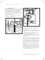
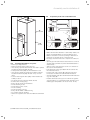
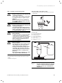
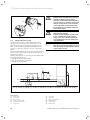
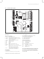
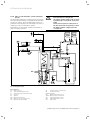
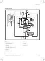
6.6.3 Direct heating operation (Hydraulic plan 6)
The heat pump is connected directly to the underfloor
heating circuit. Control is carried out using energy balance control by default (see Chap. 8.4.2). To do this, the
VF 2 flow temperature sensor must be connected (floor
protection circuit).
Furthermore, the heat pump actuates the internal domestic hot water cylinder.
Note!
If hydraulic decoupling of the heating
circuit is necessary, then fit a low loss
header as well as an external heating
circuit pump.
42a
16
31
AF
31
18
33
SP
230 V ~
230 V ~
43
42a
WQ
A M B
AB
64
AB
32
B MA
Sole
B
M
A
42b
Hzg.
AB
65
Fig. 6.10 Hydraulic plan 6
Key to Fig. 6.10
16
Outdoor sensor
18
VF 2 feed temperature sensor
31
Control valve with position indication
32
Cap valve
33
Air separator/Dirt filter
42a
Expansion relief valve
42b
Expansion vessel
43
Safety group for hot water pipe
64
Brine pump
65
Cooling heat exchanger
WQ
Heat Source
Brine
Evaporator
Heating Condenser
geoTHERM exclusive VWS 0020051614_00 installation instructions
h
Note!
If you have fitted a low loss header between the heat pump and the heating
system, then the VF 2 temperature sensor must be mounted in the flow line
from the low loss header to the heating
system.
39