1
Attachment to the control valve – Mounting parts and accessories
4.5
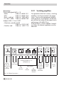
Reversing amplifier for
double-acting actuators
For the use with double-acting actuators, the
positioner must be fitted with a reversing
amplifier, e.g. the SAMSON Type 3710 Reversing Amplifier (see Mounting and Operating Instructions EB 8392 EN).
4.6
Attaching an external
position sensor
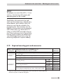
Refer to Table 7 on page 44 for the required
mounting parts and accessories.
In the positioner version with an external position sensor, the sensor placed in a separate housing is attached over a plate or
bracket to the control valve. The travel
pick-off corresponds to that of a standard
device.
The positioner unit can be mounted as required to a wall or a pipe.
For the electrical connection a 10 meter
connecting lead with M12x1 connectors is
included in the scope of delivery.
Note:
– In addition, the instructions in sections
5.1 and 5.2 apply for the pneumatic and
electrical connection.
Operation and setting are described in
sections 7 and 8.
– Since 2009, the back of the position sensor (20) is fitted with two pins acting as
mechanical stops for the lever (1). If this
position sensor is mounted using old
mounting parts, two corresponding
Ø 8 mm holes must be drilled into the
mounting plate/bracket (21).
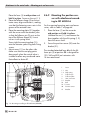
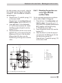
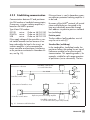
4.6.1 Mounting the position sensor with direct attachment
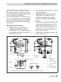
Type 3277-5 Actuator with 120 cm²
The signal pressure from the positioner is
routed over the signal pressure connection
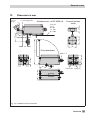
of the connecting plate (9, Fig. 13 left) to the
actuator diaphragm chamber. To proceed,
first screw the connecting plate (9) included
in the accessories onto the actuator yoke.
Turn the connecting plate (9) so that the
correct symbol for the fail-safe position
"Actuator stem extends" or "Actuator
stem retracts" is aligned with the marking
(Fig. 13, below).
Make sure that the gasket for the connecting plate (9) is correctly inserted.
The connecting plate has boreholes with
NPT and G threads.
Seal the threaded connection that is not
used with the rubber seal and square plug.
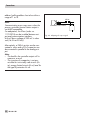
4
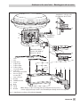
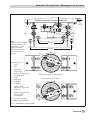
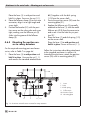
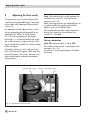
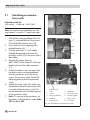
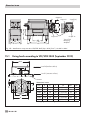
Fig. 12 · Positioner unit with sensor mounted on a
micro-flow valve
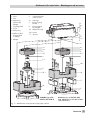
For the pneumatic connection either a connecting plate (6) or a pressure gauge
bracket (7) must be fixed to the housing, depending on the accessories chosen. Make
sure the seal rings (6.1) are correctly inserted (see Fig. 6 on page 27, bottom right).
34
EB 8384-6 EN
4
4