1
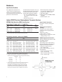
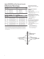
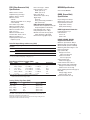
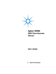
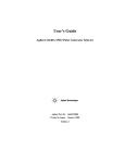
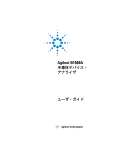
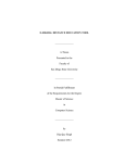
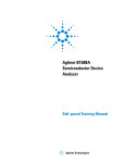
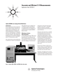
Agilent 4155C Semiconductor
Parameter Analyzer
Agilent 4156C Precision Semiconductor
Parameter Analyzer
Data Sheet
Introduction
Agilent 4155C and 4156C
Basic functions
• Set measurement and/or stress
conditions
• Control measurement and/or
stress execution
• Perform arithmetic calculations
• Display measured and calculated results
on the LCD display
• Perform graphical analysis
• Store and recall measurement setups, and
measurement and graphical display data
• Dump to printers or plotters
for hardcopy output
• Perform measurement and analysis with
built-in instrument BASIC
• Self test, Auto calibration
4155C
4156C
4xMPSMU
4xHRSMU
2xVMU
2xVMU
2xVSU
2xVSU
Desktop
EasyEXPERT
Desktop
EasyEXPERT
41501B (Optional)
Configuration
2xPGU (Option)¹
The 4155C and 4156C are both furnished
with Desktop EasyEXPERT standard edition.
GNDU
If you want the Desktop EasyEXPERT Plus
edition, you can request the B1541A-002
when you order a 4155C or 4156C. For more
information about the Desktop EasyEXPERT
Plus, please refer to page 11 of this data
sheet.
HPSMU (Option) or
2xMPSMU (Option)¹
1. Minimum number of installable MPSMU
or PGU is two.
SMU: Source monitor unit
Display resolution: 6 digits at each current
range (0.01 fA display resolution at 10
pA range)2
HRSMU: High Resolution SMU
(1 fA/2 μV to 100 mA/100 V)
MPSMU: Medium Power SMU
(10 fA/2 μV to 100 mA/100 V)
HPSMU: High Power SMU
(10 fA/2 μV to 1 A/200 V)
VMU: Voltage Monitor Unit
(0.2 μV resolution in differential mode)
VSU: Voltage Source Unit
PGU: Pulse Generator Unit
(1 channel)
GNDU: Ground Unit
2. Accuracy not guaranteed. Minimum
guaranteed resolution is 1 fA at 10 pA range.
Hardware
Specification Condition
The “supplemental” information and
“typical” entries in the following specifications are not warranted, but provide
useful information about the functions and
performance of the instruments.
The measurement and output accuracy are
specified at the rear panel connector terminals when referenced to the Zero Check
terminal under the following conditions:
1. 23 °C ±5 °C (double between 5 °C to
18 °C, and 28 °C to 40 °C if not noted
otherwise)
2. After 40 minutes warm-up
3. Ambient temperature change less than
±1 °C after auto calibration execution.
4. Integration time: medium or long
5. Filter: ON (for SMUs)
6. Kelvin connection (for HRSMU, HPSMU,
and GNDU)
7. Calibration period: 1 year
Agilent 4156C Precision Semiconductor Parameter Analyzer
HRSMU (High Resolution SMU) Specifications
Output Terminal/Connection:
Voltage Range, Resolution, and Accuracy (HRSMU)
Dual triaxial connectors, Kelvin (remote
sensing)
Voltage
Range
±2 V
±20 V
±40 V
±100 V
Set Reso.
Set Accuracy
100 μV
1 mV
2 mV
5 mV
±(0.02%+400 μV)
±(0.02%+3 mV)
±(0.025 %+6 mV)
±(0.03%+15 mV)
Meas.
Reso.
2 μV
20 μV
40 μV
100 μV
Meas. Accuracy
±(0.01%+200 μV)
±(0.01%+1 mV)
±(0.015%+2 mV)
±(0.02%+5 mV)
Max.
Current
100 mA
100 mA
1
2
1 100 mA (Vout ≤20 V), 50 mA (20 V<Vout≤40 V)
2 100 mA (Vout ≤20 V), 50 mA (20 V<Vout≤40 V), 20 mA (40 V<Vout≤100 V)
Current Range, Resolution, and Accuracy (HRSMU)
Current
Range
±10 pA
±100 pA
±1 nA
±10 nA
±100 nA
±1 μA
±10 μA
±100 μA
±1 mA
±10 mA
±100 mA
Set
Reso.
10 fA
10 fA
100 fA
1 pA
10 pA
100 pA
1 nA
10 nA
100 nA
1 μA
10 μA
Set Accuracy
Meas.
Reso.
±(4%+400 fA) 1, 2
1 fA
±(4%+400 fA) 1, 2
1 fA
10 fA
±(0.5%+0.7 pA+1 fA×Vout) 2
±(0.5%+4 pA+10 fA×Vout)
10 fA
±(0.12%+40 pA+100 fA×Vout) 100 fA
±(0.12%+400 pA+1 pA×Vout) 1 pA
±(0.07%+4 nA+10 pA×Vout)
10 pA
±(0.07%+40 nA+100 pA×Vout) 100 pA
±(0.06%+400 nA+1 nA×Vout) 1 nA
±(0.06%+4 μA+10 nA×Vout)
10 nA
±(0.12%+40 μA+100 nA×Vout) 100 nA
Meas. Accuracy
Max. V
±(4%+20 fA+1 fA×Vout/100) 1, 2
±(4%+40 fA+10 fA×Vout/100) 1, 2
±(0.5%+0.4 pA+1 fA×Vout) 2
±(0.5%+2 pA+10 fA×Vout)
±(0.1%+20 pA+100 fA×Vout)
±(0.1%+200 pA+1 pA×Vout)
±(0.05%+2 nA+10 pA×Vout)
±(0.05%+20 nA+100 pA×Vout)
±(0.04%+200 nA+1 nA×Vout)
±(0.04%+2 μA+10 nA×Vout)
±(0.1%+20 μA+100 nA×Vout)
100 V
100 V
100V
100V
100V
100V
100V
100V
100V
100V
1
The accuracy is applicable when offset cancellation has been performed.
2
The offset current specification is multiplied by one of the following factors
depending upon the ambient temperature and humidity (RH = Relative Humidity):
Temperature
3
Humidity %
RH
5 - 60
60 - 80
5 °C to 18 °C
×2
×2
18 °C to 28 °C
×1
×2
28 °C to 40 °C
×2
×5
100 V (Iout≤20 mA), 40 V (20 mA<Iout≤50 mA), 20 V (50 mA<Iout≤100 mA)
Vout is the output voltage in volts. Iout is the output current in amps.
For example, accuracy specifications are given as ±% of set/measured
value (0.04%) plus offset value (200 nA+1 nA×Vout) for the 1 mA range.
The offset value consists of a fixed part determined by the set/measurement range and a proportional part that is multiplied by Vout or Vout/100.
2
3
Voltage/Current Compliance
(Limiting):
The SMU can limit output voltage or
current to prevent damaging the device
under test.
Voltage: 0 V to ±100 V
Current: ±100 fA to ±100 mA
Compliance Accuracy: Same as the current
(voltage) settling accuracy.
HRSMU Supplemental Information:
Maximum allowable cable resistance when
using Kelvin connection
(Force, Sense): 10 Ω
Typical voltage source output resistance
(Force line/non-Kelvin connection): 0.2 Ω
Voltage measurement input resistance/
current source output resistance:
≥1015 Ω (10 pA range)
Current compliance setting accuracy for
opposite polarity:
10 pA to 10 nA range: V/I setting
accuracy ±12% of range
100 nA to 100 mA range: V/I setting
accuracy ±2.5% of range
Agilent 4156C Semiconductor Parameter Analyzer
Output Terminal/Connection:
MPSMU (Medium Power SMU) Specifications
Single triaxial connector, non-Kelvin
(no remote sensing)
Voltage Range, Resolution, and Accuracy (MPSMU)
Voltage
Range
±2 V
±20 V
±40 V
±100 V
Set
Reso.
100 μV
1 mV
2 mV
5 mV
Set Accuracy
±(0.03%+900 μV+0.3×Iout)
±(0.03%+4 mV+0.3×Iout)
±(0.03%+7 mV+0.3×Iout)
±(0.04%+15 mV+0.3×Iout)
Meas.
Reso.
2 μV
20 μV
40 μV
100 μV
Meas. Accuracy
±(0.02%+700 μV+0.3×Iout)
±(0.02%+2 mV+0.3×Iout)
±(0.02%+3 mV+0.3×Iout)
±(0.03%+5 mV+0.3×Iout)
Max.
Current
100 mA
100 mA
1
2
1 100 mA (Vout ≤20 V), 50 mA (20 V<Vout ≤40 V)
2 100 mA (Vout ≤20 V), 50 mA (20 V<Vout ≤40 V), 20 mA (40 V<Vout≤100 V)
Set
Reso.
100 fA
1 pA
10 pA
100 pA
1 nA
10 nA
100 nA
1 μA
10 μA
Set Accuracy
Meas.
Reso.
±(0.5%+3 pA+2 fA×Vout)
10 fA
±(0.5%+7 pA+20 fA×Vout)
10 fA
±(0.12%+50 pA+200 fA×Vout) 100 fA
±(0.12%+400 pA+2 pA×Vout) 1 pA
±(0.12%+5 nA+20 pA×Vout)
10 pA
±(0.12%+40 nA+200 pA×Vout) 100 pA
±(0.12%+500 nA+2 nA×Vout) 1 nA
±(0.12%+4 μA+20 nA×Vout)
10 nA
±(0.12%+50 μA+200 nA×Vout) 100 nA
The SMU can limit output voltage or
current to prevent damaging the device
under test.
Voltage: 0 V to ±100 V
Current: ±1 pA to ±100 mA
Compliance Accuracy: Same as the current
(voltage) settling accuracy.
MPSMU Supplemental Information:
Current Range, Resolution, and Accuracy (MPSMU)
Current
Range
±1 nA
±10 nA
±100 nA
±1 μA
±10 μA
±100 μA
±1 mA
±10 mA
±100 mA
Voltage/Current Compliance
(Limiting):
Meas. Accuracy
Max. V
±(0.5%+3 pA+2 fA×Vout)
±(0.5%+5 pA+20 fA×Vout)
±(0.1%+30 pA+200 fA×Vout)
±(0.1%+200 pA+2 pA×Vout)
±(0.1%+3 nA+20 pA×Vout)
±(0.1%+20 nA+200 pA×Vout
±(0.1%+300 nA+2 nA×Vout)
±(0.1%+2 μA+20 nA×Vout)
±(0.1%+30 μA+200 nA×Vout)
100 V
100 V
100 V
100 V
100 V
100 V
100 V
100 V
1
Typical voltage source output
resistance: 0.3 Ω
Voltage measurement input
resistance/current source output resistance: ≥1013 Ω (1 nA range)
Current compliance setting accuracy for
opposite polarity:
1 nA to 10 nA range: V/I setting accuracy
±12% of range
100 nA to 100 mA range: V/I setting
accuracy ±2.5% of range
1 100 V (Iout ≤20 V), 40 V (20 mA<Iout≤50 mA), 20 V (50 mA<Iout≤100 mA)
100
Vout is the output voltage in volts. Iout is the output current in amps.
For example, accuracy specifications are given as ±% of set/measured
value (0.1%) plus offset value (30 pA+200 fA×Vout) for the 100 nA range.
The offset value consists of a fixed part determined by the set/
measurement range and a proportional part that is multiplied by Vout.
Current (mA)
MPSMU measurement
and output range
50
20
-100
-40 -20
20 40
100
Voltage (V)
-20
-50
-100
VSU and VMU specifications are common to both the 4155C and 4156C
VSU (Voltage Source Unit)
Specifications
VMU (Voltage Monitor Unit)
Specifications
VMU Measurement Range,
Resolution, and Accuracy:
VSU Output Range:
VMU Differential Mode Range,
Resolution, and Accuracy:
Voltage
Range
±2 V
±20 V
Voltage Meas.
Range Reso.
±20 V
1 mV
Meas. Accuracy
±(0.05% of setting +10 mV)1
1 Specification is applicable under no load current.
Max. Output Current: 100mA
VSU Supplemental Information:
Output resistance: 0.2 Ω (typical)
Maximum load capacitance: 10 μF
Maximum slew rate: 0.2 V/μs
Current limit: 120 mA (typical)
Output Noise: 1 mV rms (typical)
Diff V
Range
±0.2 V
±2 V
Meas.
Reso.
0.2 μV
2 μV
Meas.
Accuracy
±(0.03%+10 μV+0.3 μV×Vi)
±(0.02%+100 μV+3 μV×Vi)
Max. Common Mode Voltage: ± 20 V
Note: Vi is the input voltage of VMU2 in volts.
For example, accuracy specifications are given as ±%
of set/measured value (0.02%) plus offset value (100
μV+3 μV×Vi) for the 2 V range. The differential mode
offset value consists of a fixed part determined by the
measurement range and a proportional part that is
multiplied by Vi.
Meas.
Reso.
2 μV
20 μV
Meas.
Accuracy
±(0.02%+200 μV)
±(0.02%+1 mV)
VMU Supplemental Information:
Input Impedance: ≥1 GΩ
Input leakage current (@0 V): ≤500 pA
Measurement noise: 0.01% of range (p-p)
(typical) when integration time is 10 PLC
Differential mode measurement noise:
0.005% of range (p-p) (typical) when
integration time is short.
3
Agilent 41501B SMU and Pulse Generator Expander
HPSMU (High Power SMU) Specifications
Output Terminal/Connection:
Voltage Range, Resolution, and Accuracy (HPSMU)
Voltage
Range
±2 V
±20 V
±40 V
±100 V
±200 V
Set.
Reso.
100 μV
1 mV
2 mV
5 mV
10mV
Set. Accuracy
±(0.03%+900 μV)
±(0.03%+4 mV)
±(0.03%+7 mV)
±(0.04%+15 mV)
±(0.045%+30 mV)
Meas.
Reso.
2 μV
20 μV
40 μV
100 μV
200 μV
Meas. Accuracy
Max.
Current
1A
1A
500 mA
125 mA
50 mA
±(0.02%+700 μV)
±(0.02%+2 mV)
±(0.02%+3 mV)
±(0.03%+5 mV)
±(0.035%+10 mV)
Set.
Reso.
100 fA
1 pA
10 pA
100 pA
1 nA
10 nA
100 nA
1 μA
10 μA
100 μA
Set.Accuracy
Meas.
Reso.
±(0.5%+3 pA+2 fA×Vout)
10 fA
±(0.5%+7 pA+20 fA×Vout)
10 fA
±(0.12%+50 pA+200 fA×Vout) 100 fA
±(0.12%+400 pA+2 pA×Vout) 1 pA
±(0.12%+5 nA+20 pA×Vout)
10 pA
±(0.12%+40 nA+200 pA×Vout) 100 pA
±(0.12%+500 nA+2 nA×Vout) 1 nA
±(0.12%+4 μA+20 nA×Vout)
10 nA
±(0.12%+50 μA+200 nA×Vout) 100 nA
±(0.5%+500 μA+2 μA×Vout)
1 μA
Voltage/Current Compliance
(Limiting):
Voltage: 0 V to ±200 V
Current: ±1 pA to ±1 A
Compliance Accuracy: Same as the current
(voltage) settling accuracy.
HPSMU Supplemental Information:
Current Range, Resolution, and Accuracy (HPSMU)
Current
Range
±1 nA
±10 nA
±100 nA
±1 μA
±10 μA
±100 μA
±1 mA
±10 mA
±100 mA
±1 A
Dual triaxial connectors, Kelvin (remote
sensing)
Meas. Accuracy
Max. V
±(0.5%+3 pA+2 fA×Vout)
±(0.5%+5 pA+20 fA×Vout)
±(0.1%+30 pA+200 fA×Vout)
±(0.1%+200 pA+2 pA×Vout)
±(0.1%+3 nA+20 pA×Vout)
±(0.1%+20 nA+200 pA×Vout
±(0.1%+300 nA+2 nA×Vout)
±(0.1%+2 μA+20 nA×Vout)
±(0.1%+30 μA+200 nA×Vout)
±(0.5%+300 μA+2 μA×Vout)
200 V
200 V
200 V
200 V
200 V
200 V
200 V
200 V
1
2
1 200 V (Iout ≤50 mA), 100 V (50 mA<Iout≤100 mA)
2 200 V (Iout ≤50 mA), 100 V (50 mA<Iout≤125 mA), 40 V (125 mA<Iout≤500 mA), 20 V (500 mA<Iout≤1 mA)
Vout is the output voltage in volts. Iout is the output current in amps. For example, accuracy specifications
are given as ±% of set/measured value (0.1%) plus offset value (30 pA+200 fA×Vout) for the 100 nA range.
The offset value consists of a fixed part determined by the set/measurement range and a proportional part
that is multiplied by Vout.
1000
Maximum allowable cable resistance when
using Kelvin connection:
Force: 0.7 Ω (100 mA to 1 A)
Force: 10 Ω (≤100 mA)
Sense: 10 Ω
Typical voltage source output resistance
(Force line/non-Kelvin connection): 0.2 Ω
Voltage measurement input resistance/
current source output resistance:
≥1013 Ω (1 nA range)
Current compliance setting accuracy for
opposite polarity:
1 nA to 10 nA range: V/I setting
accuracy ±12% of range
100 nA to 1 A range: V/I setting
accuracy ±2.5% of range
Current (mA)
HPSMU measurement
and output range
500
-200
-100
-40
125
50
-20
-50
-125
-500
-1000
4
20
40
100
200
Voltage (V)
PGU (Pulse Generator Unit)
Specifications
Modes: Pulse or constant
Amplitude: 0 Vp-p to 40 Vp-p
Window: -40.0 V to +40.0 V
Maximum current:
±100 mA
±200 mA (pulse width: ≤1 ms, average
current 100 mA)
Pulse width: 1.0 μs to 9.99 s
Minimum resolution: 100 ns
Pulse period: 2.0 μs to 10.0 s
Minimum resolution: 100 ns
Delay: 0 s to 10 s
Minimum resolution: 100 ns
Transition time: 100 ns to 10 ms
Minimum resolution: 1 ns
Output impedance: 50 Ω or low
impedance (≤1 Ω)
Burst count range: 1 – 65535
Pulse parameter accuracy:
Period: ±(2% +2 ns)
Width: ±(3% +2 ns)
Delay: ±(2% +40 ns)
Transition time: ±(5% +10 ns)
Trigger output:
Level: TTL
Timing: Same timing and width as
PGU1 pulse output
PGU Supplemental Information
Overshoot: ≤±5% of amplitude ±10 mV (50
Ω output impedance to 50 Ω load)
Pulse width jitter: 0.2% + 100 ps
Pulse period jitter: 0.2% + 100 ps
Maximum slew rate: 100 V/μs (50 Ω
output impedance to 50 Ω load)
Noise: 0.2% of range (@ DC output)
1
Resolution
Accuracy
4 mV
8 mV
4 mV
8 mV
±(1% of Base +50 mV +1% of Pulse)
±(1% of Base +50 mV +1% of Pulse)
±(3% of Base +50 mV)
±(3% of Base +50 mV)
Note: DC output is performed by the Base Parameter.
1 Accuracy is specified at leading edge - trailing edge = 1 μs
Pulse Range and Pulse Parameter (PGU)
Range
1
2
3
4
5
6
Period
2 μs -100 μs
100 μs - 1000 μs
1 ms - 10 ms
10 ms - 100 ms
100 ms - 1000 ms
1 s - 10 s
Width
1 μs - 99.9 μs
1 μs - 999 μs
.01 ms - 9.99 ms
0.1 ms - 99.9 ms
1 ms - 999 ms
0.01 s - 9.99 s
Same as 4155C MPSMU.
GNDU (Ground Unit)
Specifications
Output Voltage: 0 V ±100 μV
Maximum sink current: 1.6 A
Output terminal/connection:
Single triaxial connector,
Kelvin (remote sensing)
GNDU Supplemental Information
Load Capacitance: ≤1 μF
Cable resistance:
Force ≤1 Ω
Sense ≤10 Ω
HRSMU, MPSMU, HPSMU
Supplemental Information
Pulse/DC Output Voltage and Accuracy (PGU)
Set
Voltage Range
Parameter
Base
±20 V
±40 V
Pulse
±20 V
±40 V
MPSMU Specifications
Delay
0 - 100 μs
0 - 1000 μs
0 - 10 ms
0 - 100 ms
0 - 1000 ms
0 - 10 s
Note: Pulse width is defined when leading time is equal to trailing time.
PGU2 must be set in the same range as PGU1
Set Resolution
0.1 μs
1 μs
10 μs
100 μs
1 ms
10 ms
Maximum capacitive load: 1000 pF
Maximum guard capacitance: 900 pF
Maximum shield capacitance: 5000 pF
Maximum guard offset voltage: ±1 mV
Noise characteristics
(typical, Filter: ON):
Voltage source noise:
0.01% of V range (rms)
Current source noise:
0.1% of I range (rms)
Voltage monitor noise:
0.02% of V range (p-p)
Current monitor noise: 0.2% of I
Output overshoot (typical, Filter: ON):
Voltage source: 0.03% of V range
Current source: 1% of I range
Range switching transient noise (typical,
Filter: ON):
Voltage ranging: 250 mV
Current ranging: 10 mV
Maximum slew rate: 0.2 V/μs
Leading/Trailing Edge Times (PGU)
Range
100 ns - 1000 ns
0.5 μs - 10 μs
5.0 μs - 100 μs
50 μs - 1000 μs
0.5 ms - 10 ms
Set Resolution
1 ns
10 ns
100 ns
1 μs
10 μs
Accuracy
±(5% + 10 ns)
±(5% + 10 ns)
±(5% + 10 ns)
±(5% + 10 ns)
±(5% + 10 ns)
Restrictions:
Pulse width < Pulse Period, Delay time < Pulse period, Leading time < Pulse width × 0.8
Trailing time < (Pulse period - Pulse width) × 0.8
Period, width, and delay of PGU1 and PGU2 must be in the same range. Leading time and
trailing time for a PGU must be in the same range.
5
Capacitance Calculation Accuracy (Supplemental Data)
Accuracy is derived from the current range, voltage range, capacitance measurement and
leakage current measurement integration times, and the guard capacitance of cabling
and step voltage. The information in the chart below is based on the following conditions: Voltage Range ±20 V; Voltage Step: 100 mV; Guard Capacitance: 100 pF; Equivalent
parallel resistance of DUT: 1 × 10¹⁵ Ω. The ratio of integration times for capacitance
measurement and leakage current measurement is 1:1.
HRSMU
Current
Range
10 pA/
100 pA
1 nA
10 nA
Integration
Time
0.5 sec
1 sec
2 sec
0.1 sec
0.5 sec
2 sec
0.1 sec
0.5 sec
2 sec
10 sec
Max. Meas.
Value
100 pF/1 pF
2 pF/20 pF
76 pF/760 pF
700 pF
4.5 nF
18 nF
7 nF
45 nF
180 nF
940 nF
Resolution
Integration
Time
0.1 sec
0.5 sec
2 sec
0.1 sec
0.5 sec
2 sec
10 sec
Max. Meas.
Value
700 pF
4.5 nF
18 nF
7 nF
45 nF
180 nF
940 nF
Resolution
5 fF
10 fF
20 fF
10 fF
40 fF
200 fF
10 fF
40 fF
200 fF
1 pF
Accuracy
Reading %
4.2
4.3
4.3
0.84
0.85
0.93
0.84
0.85
0.93
1.3
Offset
Accuracy
Reading %
0.91
0.94
1.0
0.91
0.94
1.0
1.6
Offset
70 fF
90 fF
130 fF
160 fF
280 fF
740 fF
200 fF
440 fF
1.4 pF
6.2 pF
MPSMU
Current
1 nA
10 nA
10 fF
40 fF
200 fF
10 fF
40 fF
200 fF
1 pF
170 fF
340 fF
1 pF
180 fF
480 fF
1.6 pF
7.6 pF
Current compliance must be smaller than the current range. The capacitance of the DUT and measurement path must
be smaller than the maximum measurement value.
Functions
Measurement Setup
Setting
• Fill-in-the-blanks using front-panel or
full-size external keyboard
• Load settings from floppy disk or via the
LAN port
• Program using internal Instrument BASIC
or via GPIB
• HELP Function
• Library: Default measure setup, Vce-Ic,
Vds-Id, Vgs-Id, and Vf-If are predefined
softkeys
• User-defined measurement setup library
• Auto file load function on power-up
6
Measurement
The 4155C and 4156C can perform dc
or pulsed force/measure, and stress
force. For dc, voltage/current sweep and
sampling (time domain) measurements are
available.
Voltage/Current Sweep
Measurement Characteristics
Each SMU and VSU can sweep
using VAR1 (primary sweep),
VAR2 (subordinate sweep), or
VAR1 (synchronous sweep).
VAR1
Primary sweep controls the staircase (dc
or pulsed) voltage or current sweep.
Maximum number of steps: 1001 for one
VAR1 sweep.
Sweep type: linear or logarithmic
Sweep direction: Single or double sweep
Hold time: Initial wait time or wait time
after VAR2 is set: 0 to 655.35 s with 10
ms resolution
Delay time: Wait time from VAR1 step to
the start of the measurement: 0 to 65.535
s with 100 μs resolution
VAR2
Subordinate linear staircase or linear
pulsed sweep. After primary sweep
is completed, the VAR2 unit output is
incremented.
Maximum number of steps: 128
VAR1'
Staircase or pulse sweep synchronized with
the VAR1 sweep. Sweep is made with a
user specified ratio and offset value. VAR1'
output is calculated as VAR1' = a × VAR1
+ b, where “a” is the user specified ratio
and “b” is the user specified offset value.
CONSTANT
A source unit can be set as a constant
voltage or current source depending on
the unit.
PULSE
One of the SMUs can be set as a pulse
source.
Pulse width: 0.5 ms to 100 ms, 100 μs
resolution.
Pulse period: 5 ms to 1 s (pulse
width + 4 ms), 100 μs resolution.
SMU pulse setting accuracy
(supplemental information, at fixed
range measurement except multichannel
measurement):
Width: 0.5% + 50 μs
Period: 0.5% + 100 μs
Trigger output delay for pulsed measurement: 0 - 32.7 ms with
100 μs resolution (< pulse width).
Sampling (Time Domain)
Measurement Characteristics
Displays the time sampled voltage/current
data versus time.
Max. sampling points: 10,001 (linear)
Sampling mode: linear, log, and thinned-out
Note: The thinned-out mode is similar to reverse-log
sampling. Sampling measurement continues by thinning out older data until the sampling completion
condition is satisfied.
Sampling interval range and resolution:
Linear scale (auto mode):
60 μs to 480 μs range:
20 μs resolution
480 μs to 1 s range:
80 μs resolution
1 s to 65.535 s range:
2 ms resolution
Linear scale (no limit mode), log scale, and
thinned-out modes:
560 μs (720 μs at thinned-out mode)
to 1 s range: 80 μs resolution
1 s to 65.535 s range:
2 ms resolution
Note: The following conditions must be set when initial
interval is less than 2 ms.
• Number of measurement channels: 1
• Measurement ranging: fixed range
• Stop condition: disable
Hold time:
Initial wait time: 0.03 s to 655.35 s,
100 μs resolution
Sampling measurement stop condition: A
condition to stop the sampling can be
defined.
Sampling interval setting accuracy
(supplemental data):
0.5% + 10 μs (sampling interval
≤480 μs)
0.5% + 10 μs (480 μs ≤sampling
interval <2 ms)
0.5% + 100 μs (2 ms ≤sampling
interval)
C-V Measurement Characteristics
Capacitance Calculation Accuracy
Arithmetic Functions User Functions
Accuracy is dependent on accuracy of
the current measurement and voltage
measurement and the stray capacitance
and leakage current of measurement path,
etc. (Refer to the chart in supplemental
data).
Up to six USER FUNCTIONS can be defined
using arithmetic expressions.
Measured data and analyzed variables
from graphics analysis (marker, cursor, and
line data) can be used in the computation.
The results can be displayed on the LCD.
Zero Offset
Arithmetic Operators
Cancels stray capacitance of the fixtures
and test leads.
+, -, *, /, ^, LGT (logarithm, base 10),
LOG (logarithm, base e), EXP (exponent),
DELTA, DIFF (differential), INTEG (integration), MAVG (moving average), SQRT,
ABS (absolute value), MAX, MIN, AVG
(averaging), COND (conditional evaluation).
Leakage Current Compensation
Cancels the influence of the leakage
current to the capacitance measurement.
Stress Force Characteristics
Keyboard constants are stored in memory
as follows:
q: Electron Charge, 1.602177 E-19 C
k: Boltzman’s Constant,
1.380658 E-23
ε (e): Dielectric Constant of Vacuum,
8.854188 E-12
SMU, VSU, and PGU output can be forced
for the user specified period.
Stress time set range: 500 μs to 31,536,000
s (365 days)
Resolution:
100 μs (500 μs ≤stress time ≤10 s)
10 ms (10 s <stress time ≤31,536,000 s)
Burst pulse count: 1–65,535 (PGU only)
Trigger: The 4155C and 4156C output a
gate trigger while stress channels are
forcing stress.
The following unit symbols are also available on the keyboard: f (10-15 ),
p (10-12 ), n (10-9 ), u or µ (10-6 ),
m (10-3 ), K (103 ), M (106 ), G (109 )
Knob Sweep
Analysis Capabilities
Overlay Graph Comparison
In knob sweep mode, sweep range is
controlled instantaneously with the
front-panel rotary knob. Only the Channel
Definition page need be defined.
Standby Mode
SMUs in “Standby” remain programmed to
their specified output value even as other
units are reset for the next measurement.
Other Characteristics
Capacitance is a calculated value
derived from the following equation:
DQ
C = ———
DV
DQ is the change in charge when DV, the
step voltage, is applied by the SMU; DQ
is derived from the measurement current
(amps) and the integration time (seconds).
Measurement Control: Single, append,
repeat, and stop
Stress Control: Stress force and stop
SMU Setting Capabilities: Limited
autoranging, voltage/current compliance, power compliance, automatic
sweep abort functions, self-test, and
self-calibration.
Maximum Measurable Value
Arithmetic and Analysis
Functions
Maximum measurable value depends
on the current range, integration time, and
step voltage (refer to the chart in supplemental data).
Physical Constants
Engineering Units
A graphics plot can be stored and later
recalled as an overlay plane. Four overlay
planes can be stored. One plane can be
overlaid onto the current data.
Marker
Marker to min/max, interpolation, direct
marker, and marker slip
Cursor
Long and short, direct cursor.
Line
Two lines, normal mode, grad mode,
tangent mode, and regression mode.
Scaling
Auto scale and zoom.
Data Variable Display
Up to two user defined parameters can be
displayed on the graphics screen.
Read Out Function
The read out functions are built-in functions for reading various values related to
the marker, cursor, or line.
7
Automatic Analysis Function
Hard Copy via Network Interface
Repeating and Automating Test
On a graphics plot, the markers and lines
can be automatically located using the
auto analysis setup. Parameters can be
automatically determined using automatic
analysis, user function, and read out
functions.
The network interface has lpr client
capability.
Instrument Control
User Variable
Note: High-resolution mode takes significantly greater
CPU time to generate, so its use is recommended for
final reports only.
Display the data on the LCD via GPIB or
instrument BASIC.
Output
Display
Display Modes
Graphics and list.
Graphics Display
X-Y or X-Y1/Y2 plot of source current/
voltage, measured current/voltage, time,
or calculated USER FUNCTION data.
List Display
Measurement data and calculated USER
FUNCTION data are listed in conjunction
with VAR1 step number or time domain
sampling step number. Up to eight data
sets can
be displayed.
Display
8.4-inch diagonal color active matrix LCD,
640 dot (H × 480 dot (V). More than 99.99%
of the pixels on an LCD are active.
Hard Copy Functions
Graphics Hard Copy
Measured data and all data appearing on
the LCD can be output via GPIB, parallel
printer port, or network interface to
supported HP plotters or printers. PCL,
HR PCL (high-resolution PCL), and HP-GL
formats are supported (selectable).
Text Hard Copy
Print out setup information or measured
data list as ASCII text via GPIB, parallel
printer port, or network interface to
supported HP plotters or printers. PCL,
HR PCL, and HP GL formats are supported
(selectable).
Hard Copy File
Hard copy output can be stored to an
internal or external mass storage device
instead of sending it to a printer or plotter.
The data can be stored in PCL, HR PCL,
TIFF, HR TIFF (highresolution TIFF), or
HP GL formats.
High-Resolution (HR) Mode
This file mode is available for cases where
an extremely clean print-out or plot is
desired.
Data Storage
Mass storage device:
Built-in 3.5-inch floppy disk drive
Media: 3.5-inch 2HD or 2DD diskette
Format type: HP LIF and DOS
User area: 1.44 Mbyte (2HD) or
720 Kbyte (2DD)
File types:
Auto start program file, initial setup file,
measurement setup file, measurement
setup/result file, stress setup file,
customize file, hard copy data file, and
Instrument BASIC program and data file.
Format of data made by the HP BASIC
program:
Data made by the HP BASIC program
and data made by the Instrument BASIC
program are compatible.
Network mass storage device:
An NFS mountable mass storage device
File types:
Auto start program file, initial setup file,
measurement setup file, measurement
setup/result file, stress setup file,
customize file, and hard copy data file.
Maximum number of files allowed per
directory on network mass storage device:
199
Data storage (supplemental data):
2HD DOS format:
Available bytes: 1457 K (byte)
File size:
Measurement setup: 3843 (byte)
Stress setup: 601 (byte)
Measurement setup/result
(Typical data): 15387 (byte)
(VAR1: 101, VAR2: 5)
Customized system setup:
1661 (byte)
Hardcopy data: 30317 (byte)
(Monochrome PCL 75DPI file)
Hardcopy data: 38702 (byte)
(monochrome TIFF file)
Note: For LIF format, the total number of files is limited
to 199.
8
Agilent 4155C and 4156C function
control:
Internal or external computer controls
the 4155C and 4156C functions via the
GPIB interface
Command sets:
SCPI command set
Agilent FLEX command set
Agilent 4145B command set
Program Memory:
Using the Agilent FLEX command set,
the user can store program code in
the 4155C or the 4156C. The maximum
number of subprograms is 255 (8 bit).
External instrument remote control:
Control external equipment via the GPIB
interface.
Instrument BASIC
Instrument BASIC is a subset of
HP BASIC.
Functions:
Arithmetic operation, binary operation,
string manipulation, logical operation,
array operation, program flow control,
event-initiated branching, program
editing and debugging support, mass
storage operation, instrument control,
real-time clock, softkey operation, and
graphics.
Agilent 4145B automatic sequence
program (ASP) typing aid:
4145B ASP-like syntax softkeys are
available in instrument BASIC. A 4145B
ASP file cannot be read by the 4155C or
4156C.
Remote control:
Instrument BASIC is remote controllable
from an external computer via the GPIB
interface.
Instrument BASIC memory area (supplemental data):
Program (text) area: 16 K (byte)
Variable/stack area: 500 K (byte)
Common variable area: 600 K (byte)
Note: The memory size for common variable is
decreased when hard copy or disk operation is
performed.
Trigger
Input:
External trigger input starts a sweep
or sampling measurement or can be
used as a trigger input for continuing an
Instrument BASIC program.
Input Level:
TTL level, negative or positive edge
trigger
Output:
External edge trigger outputs can be
generated by the start of a sweep
measurement, the start of each sweep
step in a staircase sweep, the start of
each pulse leading edge for an SMU in
pulse mode, and the issuance of an an
IBASIC trigger out command execution.
In addition, you can set the trigger signal
to be active during the Stress Force
State. If you have a 41501A/B with PGU
option, you can output a synchronized
trigger output through the 41501A/B
trigger output.
Output Level:
TTL level, negative or positive logic
4145B Data Compatibility and
Syntax Commands
Setup and data file
Measurement setup and data from the
4145B can be loaded.
GPIB program
GPIB programs for the 4145B can be used
when the 4145B command set is selected.
Note: There is a possibility that GPIB programs for the
4145B will need to be modified.
Interfaces
GPIB interface:
SH1, AH1, T6, L4, SR1, RL1, PP0, DC1,
DT1, C1, C2, C3, C4, C11, E2
Parallel interface: Centronics RJ45:
Ethernet IEEE 802.3 10BASE-T for a 10
Mbps CSMA/CD local area network
External keyboard:
Compatible PC-style 101-key keyboard
(mini DIN connector)
Interlock and LED connector R-BOX control
connector
Trigger in/out
SMU/PGU selector control connector
(41501B)
Sample Application Programs
Flash EEPROM test
TDDB
Constant I (Electromigration test)
V-Ramp test
J-Ramp test
SWEAT
GO/NO-GO test
HCI degradation test
Charging pump test
Sample VEE Program
Vth measurement using the 4155C or
4156C, the E5250A, and a wafer prober.
VXI plug&play Drivers
VXI plug&play drivers for the 4155C and
4156C
Supported VXI plug&play operating
systems:
Microsoft Windows 95, 98, NT, 2000
Professional, and XP Professional
Format
Tree-structured function panel.
Panel mode for hardware configuration and
manual parameter setting.
Parameter mode for variable definition and
I/O configuration.
General Specifications
Temperature range
Operating:
+10 °C to +40 °C (if using floppy
disk drive)
+5 °C to +40 °C (if not using
floppy disk drive)
Storage: -22 °C to +60 °C
Maximum VA
4155C and 4156C: 450 VA
41501B: 350 VA
Regulatory Compliance
EMC: EN 61326-1:+A1, AS/NZS 2064.1
Safety:
CSA C22.2 NO.1010.1 (1992), IEC 610101:+A2/EN 61010-1:+A2 UL3111-1:1994
Certification:
CE, CSA, NRTL/C, C-Tick
Dimensions
4155C and 4156C: 235 mm H ×
426 mm W × 600 mm D
41501B: 190 mm H × 426 mm W ×
600 mm D
Weight (approx.)
4155C and 4156C: 21 kg
41501B: 16 kg (option 412, HPSMU + 2 ×
PGU)
4155C and 4156C
Furnished Accessories
Triaxial cable, 4 ea. (4155C)
Kelvin triaxial cable, 4 ea. (4156C)
Coaxial cable, 4 ea.
Interlock cable, 1 ea.
Keyboard, 1 ea.
User manual, 1 set
Sample application program disk, 1 ea.
Sample VEE program disk, 1 ea.
VXIplug&play drivers disk for the 4155C
and 4156C, 1 ea.
VXIplug&play drivers disk for the E5250A,
1 ea.
LAN Interface Test Adapter, 1 ea.
Humidity range
Operating:
20% to 80% RH, non-condensing and
wet bulb temperature ≤29 °C (if using
floppy disk drive)
15% to 80% RH, non-condensing and
wet bulb temperature ≤29 °C (if not
using floppy disk drive)
Storage: 5% to 90% RH,
non-condensing and wet bulb temperature ≤39 °C
Altitude
Operating: 0 to 2,000 m (6,561 ft)
Storage: 0 to 4,600 m (15,091 ft)
Power requirement
90 V to 264 V, 47 to 63 Hz
9
Accessory Specifications
Specification Condition
The “supplemental information”
and “typical” entries in the following specifications are not warranted, but provide
useful information about the functions and
performance of the instruments (23 °C ±5
°, 50% RH).
16440A SMU/Pulse Generator
Selector
The 16440A switches either an SMU or
PGU to the associated output port. You
can expand to 4 channels by adding an
additional 16440A. The channel 1 PGU port
provides a “PGU OPEN” function, which
can disconnect the PGU by opening a
semiconductor relay. The 16440A cannot
work without two pulse generator units of
the 41501A/B (SMU and Pulse Generator
Expander).
Channel configurations:
Two channels (CH1, CH2)
CH1: INPUT ports: 2 (SMU and PGU, PGU
port has additional series semiconductor
relay)
OUTPUT port: 1
CH2: INPUT ports: 2 (SMU and PGU)
OUTPUT port: 1
Voltage and Current Range
Input port Max. V
SMU
200 V
PGU
40 V
Max. I
1.0 A
0.2 A (AC Peak)
Supplemental Information
(at 23 °C ± 5 °C, 50%RH)
SMU port leakage current:
< 100 fA @100 V
SMU port residual resistance (typical):
0.2 Ω
SMU port stray capacitance (typical
@1 MHz):
Force , Common: 0.3 pF
Force , Guard: 15 pF
Guard , Common: 130 pF
PGU port residual resistance: 3.4 Ω
PGU port OFF capacitance (typical): 5 pF
PGU port OPEN capacitance (typical):
700 pF (@ 1 MHz, Vin - Vout = 0V)
10
PGU port signal transfer characteristics
Overshoot: <5% of pulse amplitude (@20
ns leading and trailing time,
50 Ω pulse generator source impedance, 50
pF and 1 MΩ in parallel load).
General Specifications
Dimensions:
50 mm H × 250 mm W × 275 mm D
Approximate weight: 1.1 kg
16441A R-BOX
The 16441A R-BOX adds a selectable
series resistor to the SMU output. You can
select the resistor from the setup page,
and the voltage drop due to the series
resistor is automatically compensated for
in the measurement result.
Measurement limitations with the 4155C
and 4156C and R-BOX:
If you measure device characteristics
including negative resistance over 1
MΩ with the 4155C/4156C and R-BOX,
there is a possibility that they cannot
be measured. There is a possibility that
the 4155C and 4156C cannot perform
measurements because of DUT oscillations even with the R-BOX. Whether
oscillation occurs or not depends upon
the DUT and measurement conditions.
Number of SMU channels that can add a
resistor: 2
Resistor values:
1 MΩ, 100 kΩ, 10 kΩ, 0 Ω (each channel)
Resistance accuracy:
0.3% (at 23 °C ±5 °C, between input/
output terminal)
Maximum voltage: 200 V
Maximum current: 1 A (0 Ω selected)
Kelvin connection: Kelvin connection is
effective only when 0 Ω is selected.
Supplemental Information (at 23 °C ±
5 °C, 50%RH)
Leakage current: <100 fA @ 100 V
General Specifications
Dimensions:
72 mm H × 250 mm W × 270 mm D
Approximate weight: 1.6 kg
16442A Test Fixture
Channel Information
SMU:
6 channels (1 triaxial connector per
channel)
3 channels (1 Kelvin triaxial connector
per channel)
VSU:
2 channels (1 BNC connector per
channel)
VMU:
2 channels (1 BNC connector per
channel)
PGU:
2 channels (1 BNC connector per
channel)
GNDU:
1 channel (1 triaxial connector)
INTLK: 6-pin connector
Supplemental Information
(at 23°C ± 5°C, 50% RH)
SMU channel:
Leakage current: 10 pA max @200 V
(Force or Sense , Common)
Stray capacitance: 15 pF max
(Force or Sense , Common)
Stray capacitance: 3 pF typical
(Force or Sense , Other SMU)
Residual resistance: 60 mΩ typical
(Force, Sense)
Guard capacitance: 70 pF max
(Force or Sense , Guard)
VSU channel residual resistance:
60 mΩ typical
VMU channel residual resistance:
60 mΩ typical
PGU channel characteristic impedance:
50 mΩ typical
GNDU channel residual resistance:
40 mΩ typical (Force, Sense)
General Specifications
Temperature range:
Operating: +5 °C to +40 °C
Storage: -40 °C to +70 °C
Humidity range:
Operating: 5% to 80% RH
(no condensation)
Storage: 5% to 90% RH at 65 °C
(no condensation)
Dimensions:
140 mm H × 260 mm W × 260 mm D
Weight (approx.): 2.5 kg
Agilent Desktop EasyEXPERT Software
Introduction
Agilent Desktop EasyEXPERT software
makes every user a parametric test
expert. The Microsoft® Windows®-based
interface is familiar, even to new engineers who have limited experience using
parametric measurement instruments.
Its unique task-based approach enables
the user to focus on the real task-at-hand
(device characterization) without having
to be a specialist at using the instrument
hardware. Desktop EasyEXPERT supports
all aspects of parametric test, from basic
manual measurements to test automation across a wafer in conjunction with a
semiautomatic wafer prober.
Features and benefits
Prober control
All popular semiautomatic wafer probers
are supported by Desktop EasyEXPERT.
You can define wafer, die and module
information for probing across an entire
wafer. You can also combine wafer prober
control with either Quick Test mode or an
application test-based test sequence to
perform multiple testing on various devices
across the wafer.
Automatic data export
Desktop EasyEXPERT has the ability to
automatically export measurement data in
real time, in a variety of formats. You can
save data to any drive connected to the
PC. If you wish, you can export data to a
network drive and view test results on your
desktop PC at the same time your instruments are performing testing in the lab.
Large application test library
Desktop EasyEXPERT comes with more
than 230 application tests conveniently
organized by device type, application, and
technology. Many of these application
tests will run on the 4155 and 4156 without
modification. You also can easily edit and
customize the furnished application tests
to fit your specific needs.
Software Functions
Operation mode
Application test mode, Classic test mode,
Quick test mode
Key Functions
Desktop EasyEXPERT offers a classic
test mode that maintains the look, feel,
and terminology of the 4155/4156 user
interface. In addition, it improves the
4155/4156 user interface by taking full
advantage of the Windows GUI features.
• Categorized and predefined application
library
• Device definition
• Measurement parameter settings
• Save/Recall My Favorite Setups
• Define/customize application library
• Execute measurement (Single/Repeat/
Append)
• Quick test execution
• Save/Recall measurement data and
settings
• Test result data management
• Import/Export device definition, measurement settings, my favorite setup,
measurement data, and application
library
• Graph plot display/analysis/printing
• Switching matrix control
• Workspace management
Easy test sequencing
Application Library
A GUI-based Quick Test mode lets you to
perform test sequencing without programming. You can select, copy, rearrange and
cut-and-paste any application tests with a
few simple mouse clicks. Once you have
selected and arranged your tests, simply
click on the measurement button to begin
running an automated test sequence.
Category:
Sample test definitions for the following
applications. They are subject to change
without notice.
Structure, CMOS, Bipolar (BJT), TFT,
Discrete, Nanotechnology, Utility
Offline capability
Desktop EasyEXPERT can run in either
online or offline mode. In offline mode you
can perform tasks such as analyzing data
and creating new application tests. This
frees up your existing analyzer from being
needed for development work and enables
you to use it for its primary purpose:
making measurements.
GUI-based classic test mode
Supported 4155/4156
Functionality
Desktop EasyEXPERT Standard
edition
• Staircase Sweep
Desktop EasyEXPERT Plus edition
The following additional functions
are supported.
• I/V-t Sampling except Thinned-out and
Logarithmic modes
• VSU/VMU except differential voltage
measurement using VMU
• PGU (41501B)
Each SMU can sweep using VAR1 (primary
sweep), VAR2 (secondary sweep), or
VAR1' (synchronous sweep).
Staircase Sweep Measurement Mode
Forces swept voltage or current, and
measures DC voltage or current. A second
channel can be programmed to output
a pulsed bias voltage or current. A third
channel can be synchronized with the
primary sweep channel as an additional
voltage or current sweep source.
Number of Steps for VAR1 and VAR1': 1
to 1001
Number of Steps for VAR2: 1 to 128
Sweep type: Linear or logarithmic
Sweep direction: Single or double sweep
Hold Time: 0 to 655.35 s, 10 ms resolution
Delay Time: 0 to 65.5350 s, 100 μs
resolution
Pulsed Sweep Measurement Mode
This mode forces pulsed swept voltage
or current, and measures DC voltage
or current. A second channel can be
programmed to output a staircase sweep
voltage or current synchronized with the
pulsed sweep output.
11
Staircase Sweep with Pulsed Bias
Measurement Mode
This mode forces swept voltage or current,
and measures DC voltage or current. A
second channel can be programmed to
output a pulsed bias voltage or current. A
third channel can be synchronized with the
primary sweep channel as an additional
voltage or current sweep source.
Sampling (Time Domain)
Measurement Mode
This mode displays the time sampled
voltage/current data (by SMU) versus
time.
Sampling channels: up to 6
For sampling intervals < 2 ms, the number
of sampling channels is 1
Sampling points: 1 to 10,001/
(number of channels)
Sampling mode: linear
Sampling interval range:
60 μs to 2 ms, 10 μs resolution
2 ms to 65.535 s, 1 ms resolution
Hold time: -30 ms to -100 μs, 100 μs
resolution
Bias hold time: 0 s
Other Measurement Characteristics
Measurement Control:
Single, Repeat, Append, and Stop
SMU Setting Capabilities:
Limited auto ranging, voltage/current
compliance, power compliance,
automatic sweep abort functions
Arithmetic and Analysis Functions
User Functions
Up to 20 user-defined functions can be
defined using arithmetic expressions.
Measured data and pre-defined variables
can be used in the computation, and the
results can be displayed on the LCD.
Graph Plot File
The graph plot can be stored as image data
to clip board or mass storage device.
File type: bmp, gif, png, emf
Output
Display Modes
X-Y graph, list display, and parameter display
X-Y Graph Display
X-axis and up to eight Y-axes
Linear and log scale
Real time graph plotting
A graphics plot can be stored and overlaid.
List Display
Scale
Measurement data and calculated user
function data are listed in conjunction
with VAR1 step number or time domain
sampling step number. Up to 20 data sets
can be displayed.
Auto scale and zoom
Marker
Marker to min/max, interpolation, direct
marker, and marker skip
Cursor
Direct cursor
Line
Two lines, normal mode, grad mode,
tangent mode, and regression mode
Automatic Analysis Function
This function is used to keep source output
after measurement. Source modules apply
the specified bias between measurements
in a quick test or application test that
defines some classic test setups, or a
repeat measurement. Also, the source
modules change the output value and the
unused modules are disconnected when
the next measurement is started.
On a graphics plot, the markers and lines
can be automatically located using the
auto analysis setup. Parameters can be
automatically determined using automatic
analysis, user function, and read out
functions.
Current Offset Cancel
Analysis Functions
Data Variable Display
Up to 20 user-defined parameters
can be displayed on the graphics
screen.
Up to 20 user-defined analysis functions can be defined using arithmetic
expressions.
Measured data, pre-defined variables
and read out functions can be used in
the computation, and the results can be
displayed on the LCD.
Read Out Functions
These built-in functions are for reading
various values related to the marker,
cursor, or line.
12
The data display window can be printed.
Only the X-Y graph can be printed.
Analysis Capabilities
Overlay Graph Comparison
Bias Hold Function
This function subtracts the offset current
from the current measurement
raw data, and returns the result as the
measurement data. It is used to compensate the error factor (offset current) caused
by the measurement
path such as the measurement cables,
manipulators, or probe card.
Graph Plot
Display Mode
Other Functions
Import/Export files
File type:
Agilent EasyEXPERT format,
XML-SS format, CSV format
Supported 4155/4156
Parameter Analyzers
System Requirements
4155B, 4156B, 4155C, and 4156C
Supported 4155/4156 firmware:
HOSTC: 03.08 or later
SMUC: 04.08 or later
The following are the minimum requirement for executing Desktop EasyEXPERT.
Operating System
and Service Pack
Processer
Memory
Display
HDD
.NET Framework
IO Libraries
(for online mode)
Supported GPIB I/F
(for online mode)
Microsoft Windows XP
Microsoft Windows
Professional SP2
VISTA Business SP1
Intel Celeron 2 GHz
Vista Certified PC with
1 GB memory
512 Megabytes DDR266
XGA 1024 × 768
(SXGA 1280 × 1024 recommended)
1 GB free space on the C drive, 10 GB (30 GB recommended)
free space on a drive for test setup/result data strage.
Microsoft .NET
Microsoft .NET
Framework Ver. 3.0
Framework Ver. 2.0
Redistributable Package
Microsoft .NET
Framework 2.0 SP1
Agilent IO Libraries Suite 15.0
Agilent 82350B
Agilent 82357A
Agilent 82357B
Supported External Instruments
Desktop EasyEXPERT Standard
edition
• Supported by switching matrix GUI:
B2200A/B2201A
• Supported by application tests: E5250A
(E5252A), 4284A/E4980A, 81110A,
3458A
Desktop EasyEXPERT Plus edition
• All auxiliary instruments supported by
Desktop EasyEXPERT Standard edition
• Also supported by switching matrix GUI:
E5250A (E5252A)
Setup Converter Tool
In addition to Desktop EasyEXPERT,
Agilent supplies a Setup File Converter tool
that runs on any Windows-based PC. This
tool can convert 4155 and 4156 measurement
setup files (files of type MES and DAT)
into equivalent Desktop EasyEXPERT
classic test mode setup files.
Attached Software
Prober Control execution files
Supported Probers:
Cascade Microtech Summit
12 K or S300
SUSS MicroTec PA200 or PA300
Vector Semiconductor VX-2000
or VX-3000
4155/56 setup file converter tool
Supported operating systems:
Microsoft Windows 2000
Professional and XP Home or
Professional
Ordering Information
B1541A
Agilent Desktop EasyEXPERT software
and measurement libraries
B1541A-001
Agilent Desktop EasyEXPERT with licenseto-use for standard edition
B1541A-002
License-to-use for Agilent
Desktop EasyEXPERT Plus
13
Agilent Email Updates
www.agilent.com/find/emailupdates
Get the latest information on the products
and applications you select.
Agilent Direct
www.agilent.com/find/agilentdirect
Quickly choose and use your test
equipment solutions with confidence.
Remove all doubt
Our repair and calibration services
will get your equipment back to you,
performing like new, when promised.
You will get full value out of your Agilent
equipment throughout its lifetime. Your
equipment will be serviced by Agilenttrained technicians using the latest
factory calibration procedures, automated repair diagnostics and genuine
parts. You will always have the utmost
confidence in your measurements.
Agilent offers a wide range of additional
expert test and measurement services
for your equipment, including initial
start-up assistance onsite education
and training, as well as design, system
integration, and project management.
For more information on repair and
calibration services, go to
www.agilent.com/find/removealldoubt
www.agilent.com
For more information on Agilent
Technologies’ products, applications or
services, please contact your local Agilent
office. The complete list is available at:
www.agilent.com/find/contactus
Americas
Canada
Latin America
United States
877 894 4414
305 269 7500
800 829 4444
Asia Pacific
Australia
China
Hong Kong
India
Japan
Korea
Malaysia
Singapore
Taiwan
Thailand
1 800 629 485
800 810 0189
800 938 693
1 800 112 929
81 426 56 7832
080 769 0800
1 800 888 848
1 800 375 8100
0800 047 866
1 800 226 008
Europe & Middle East
Austria
Belgium
Denmark
Finland
France
01 36027 71571
32 (0) 2 404 93 40
45 70 13 15 15
358 (0) 10 855 2100
0825 010 700*
*0.125 €/minute
Germany
07031 464 6333
Ireland
1890 924 204
Israel
972 3 9288 504/544
Italy
39 02 92 60 8484
Netherlands
31 (0) 20 547 2111
Spain
34 (91) 631 3300
Sweden
0200-88 22 55
Switzerland
0800 80 53 53
United Kingdom
44 (0) 118 9276201
Other European Countries:
www.agilent.com/find/contactus
Revised: October 1, 2008
Microsoft and Windows are U.S. registered
trademarks of Microsoft Corporation.
Product specifications and descriptions in this
document subject to change without notice.
© Agilent Technologies, Inc. 2009
Printed in USA, July 7, 2009
5988-9238EN