1
OPERATO£'S MANUAL
FOR
IMPORTANT
QUESTIONS,
CALL 1-800-345-8746
1-800-668-1238
in CANADA
www.TrimmerPlus.com
MANUAL
in U.S. or
DO NOT THROW AWAY
THANK
YOU
Thank you for buying this quality product. This modern
outdoor power tool will provide many hours of useful
service. You will find it to be a great labor-saving device.
This operator's manual provides you with easy-tounderstand operating instructions. Read the whole
manual and follow all the instructions to keep your new
outdoor power tool in top operating condition.
PRODUCT
REFERENCES,
AND SPECIFICATIONS
ILLUSTRATIONS,
All information, illustrations, and specifications
in this manual are based on the latest product
information available at the time of printing. We reserve
the right to make changes at any time without notice.
Copyright© 2001 MTD SOUTHWEST INC
All Rights Reserved.
TrimmerPlus® is a registered trademark of
MTD SOUTHWEST INC
II.
Rules for Safe Operation ...................
A. Important Safety Information .............
B. Safety and International Symbols .........
C. Know Your Unit .......................
3-6
3-5
5
6
Operating Instructions .....................
A. Assembling the Coupler .................
B. Special Cold Weather Starting Instructions..
C. Operating the Snow Thrower .............
D. Discharge Direction Adjustment
..........
E. Tips for Best Snow Thrower Results .......
7-8
7
8
8
8
8
Ill. Maintenance and Repair Instructions .........
A. Inspecting/Replacing the Drive Belt .......
B. Replacing the Scraper ..................
C. Storage ..............................
D. Transporting ..........................
E. Accessories/Replacement
Parts ..........
IV. Specifications
V. Warranty
...........................
...............................
9-11
9
10
11
11
11
11
12
CONTENTS OF CARTON
SERVICE
INFORMATION
ST720r Snow Thrower Add-On
1-800-345-8746
1-800-668-1238
Product Registration Card
Hanger
Operator's Manual
in the United States or
in Canada
to obtain the listing of the authorized service dealer
nearest you.
DO NOT RETURN THE UNIT TO THE RETAILER.
NOTE: PROOF OF PURCHASE WILL BE
REQUIRED FOR WARRANTY SERVICE.
Make sure this manual is carefully read and understood
before starting or operating this equipment.
THIS PRODUCT IS COVERED BY ONE OR
MORE U.S. PATENTS.
OTHER PATENTS PENDING.
A complete parts list can be viewed and printed
by going to our web site, www.TrimmerPlus.com.
Or,
you can request a copy by callingl-800-345-TRIM
(1-800-345-8746). Please have the unit model and
serial number when calling.
2
This unit should consist of the following:
Service on this unit both within and after the warranty
period should be performed only by an authorized
and approved service dealer.
Dial:
NOTE:
This product has been rated for use on both gas
and electric powerheads.
The purpose of safety symbols is to attract your
attention to possible dangers. The safety symbols,
and their explanations, deserve your careful attention
and understanding. The safety warnings do not, by
themselves, eliminate any danger. The instructions or
warnings they give are not substitutes for proper
accident prevention measures.
SYMBOL
MEANING
_IL
NOTE:
WARNING: Failure to obey a safety warning
can result in injury to yourself and others.
Always follow the safety precautions to
reduce the risk of fire, electric shock, and
personal injury.
danger,
or caution. Indicates
Attention is
SAFETY warning,
ALERT SYMBOL:
required in order to avoid serious personal
injury. May be used in conjunction with
other symbols or pictographs.
CAUTION:
Failure to obey a safety warning
may result in property damage or personal
injury to yourself or to others. Always follow
the safety precautions to reduce the risk of
fire, electric shock, and personal injury.
Advises you of information or instructions
vital to the operation or maintenance of
the equipment.
• IMPORTANT
SAFETY INFORMATION
READ ALL INSTRUCTIONS
_IL
rules
must be
followed.
safety
ARNING:
When
using For
the your
unit, own
the safety
and that of bystanders, please read these
instructions before operating the unit. Please
keep the instructions safe for later use.
,_
with
an extension
cord suitable
outdoor
use.
WARNING:
To prevent
electric for
shock,
use only
BEFORE
DANGER: Failure to obey a safety warning
will result in serious injury to yourself or to
others. Always follow the safety precautions
to reduce the risk of fire, electnc shock, and
personal injury.
OPERATING:
• Carefully read and understand the operator's manual of
the unit that powers this attachment.
• Read this operating instruction manual carefully. Be
thoroughly familiar with the controls and the proper use
of the equipment. Know how to stop the unit and
disengage the controls quickly.
• Never allow children to operate the equipment. Never
allow adults unfamiliar with the instructions to use the
unit. Never allow adults to operate the equipment without
proper instruction.
• Children and teens under the age of 15 must not use the
unit, except for teens guided by an adult.
• Keep bystanders, especially children and pets, at least
50 ft (15 m) away.
• Exercise caution to avoid slipping or falling, especially
when operating in reverse.
• Thoroughly inspect the area where the snow thrower is
to be used. Remove all doormats, sleds, boards, wires,
debris, and other foreign objects which may be thrown
by the snow thrower.
• Disengage all clutches and shift into neutral before
starting the powerhead.
•
• Do not operate the unit while under the influence of
drugs, alcohol, or medication.
• Inspect the unit before use. Replace damaged parts.
Make sure all fasteners are in place and secure. Replace
snow thrower parts that are cracked, chipped, or
damaged in any way. Make sure the snow throwing unit
is properly installed and securely fastened.
• Make sure the rotor will spin freely before attaching the
snow thrower to the powerhead.
• Dress properly. Wear adequate winter outer garments.
Wear heavy, long pants, boots, gloves and a long sleeve
shirt. Do not wear loose clothing,jewelry, short pants,
sandals or go barefoot. Secure hair above shoulder level.
• Wear footware that doesn't leak when operating the
snow thrower and that will improve footing on slippery
surfaces.
• Never attempt to make adjustments while the powerhead
is running (except when specifically recommended by
the manufacturer.)
• Let powerhead and machine adjust to outdoor
temperatures before starting to clear snow.
• Always wear safety glasses/shields or goggles at all
times during operation or while performing an adjustment
or repair to protect eyes from foreign objects that may be
thrown from the machine.
WHILE
OPERATING:
• Stay away from the discharge opening at all times. Keep
face, hands, and feet away from concealed moving or
rotating parts.
• Be attentive when using the snow thrower, and stay alert
for holes in the terrain and other hidden hazards or traffic.
• Do not use on a gravel surface or crushed rock surfaces.
Use extreme caution when crossing gravel/crushed rock
drives, walks, or roads.
3
• Afterstrikinga foreignobject,turnthepowerhead
off
andinspectthe snowthrowerfordamageForgas
powerheads:
Removewirefromthe sparkplug For
electricpowerheads:
Disconnect
thecord Repair
damagebeforerestartingandoperatingtheunit
• If theunitshouldstartto vibrateabnormally,
stopthe
powerhead
andcheckimmediately
forthecause.
Vibrationis generallya warningoftrouble.
• Stopthe powerhead
whenever
youleavetheoperating
position,beforeunclogging
the rotoror discharge
vanes,andwhenmakinganyrepairs,adjustments,
or
inspections.
• Clearsnowfromslopesbygoingup anddown.Never
goacrosstheslope.Usecautionwhenchanging
directions.Neverclearsnowfromsteepslopes.
• Neverattemptto usethesnowthrowerona roofor
anysteep,inclined,slipperysurfaces.
• Neveroperatesnowthrowerwithoutproperguards,
platesor othersafetyprotectivedevicesinplace.
• Neveroperatethesnowthrowernearglassenclosures,
automobiles,
trucks,windowwells,dropoffs, etc.
without proper adjustment of the snow discharge
angle. Keep children and pets away.
• Don't force or overload the snow thrower. Snow
thrower will perform at its best and safest when run at
the rate for which it was designed.
• Never operate the machine at high transport speeds on
slippery surfaces. Look behind and use care when
backing.
• Never direct discharge towards people or allow anyone in
front of the unit while operating.
• Disengage power to the rotor when snow thrower is
transported or not in use.
• Make sure the rotor will spin freely before attaching the
snow thrower to the powerhead.
• If the rotor will not rotate freely due to frozen ice, thaw
the unit thoroughly before attempting to operate it
under power.
• Keep the rotor clear of debris.
• Do not overreach. Keep proper footing and balance at
all times.
AFTER OPERATING:
• Follow instructions for care, maintenance, and storage
of snow thrower
• Only qualified personnel should perform any repairs
or maintenance procedures that are not described
in this manual.
• Remove residue ice or snow from the vanes and rotor
by briefly running the unit out of snow.
• Store snow thrower indoors in a dry, locked place.
Keep out of the reach of children.
• Always refer to the operator's guide instructions for
important details if snow thrower is to be stored for an
extended period
• Use only attachments and accessories approved by
the manufacturer of the snow thrower
SPECIAL
SAFETY
POWERHEADS
WARNINGS
AND SNOW
FOR ELECTRIC
THROWERS
• When cleaning, inspecting, or repairing, make certain
the rotor and all moving parts have stopped. Disconnect
the extension cord to prevent accidental starting.
• Use extension cords and receptacles as specified by
the manufacturer for all units with electric drive motors
or electric starting motors.
• Use only 3-wire outdoor extension cords that have 3prong grounding-type plugs and 3-pole receptacles
that accept the snow thrower's plug. Replace or repair
damaged cords.
• Do not abuse extension cord. Never carry snow
thrower by the cord or yank on the cord to disconnect
it from the receptacle.
• Keep the extension cord away from heat, oil, and sharp
edges to prevent damage
• If extension cord is damaged in any manner while
plugged in, pull extension cord from receptacle.
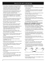
• Prevent disconnection of snow thrower powerhead
from extension cord during operation by using a plugreceptacle retaining strap, connector, or by making a
knot as shown below:
Extension
Snow
Thrower Cord
Extension
Cord
Snow
Thrower Cord
• Never discharge snow onto public roads or near
moving traffic.
• Let snow thrower run for a few minutes after clearing
snow so moving parts do not freeze.
• Never operate without good visibility or light. Always
be sure of your footing and keep a firm hold on the
handles. Walk; never run.
4
• Do not use in rain or during a snowfall. Do not use in or
around water.
• Avoid accidental starting. Don't carry plugged-in snow
thrower with finger on switch.
• Alwaysunplugtheunitandallowit to coolbefore
puttingit intostorage.Storeindoors.
• Alwaysunplugtheunitwhennotinuse,andbefore
performing
anymaintenance
or repairs.
• Never add fuel to a running engine or hot engine.
SPECIAL SAFETY WARNINGS
FOR GAS
POWERHEADS
AND SNOW THROWERS
• Do not run the engine indoors, except when starting
the engine and for transporting the snow thrower in or
out of the building. Open the outside doors; exhaust
fumes are dangerous.
• When cleaning, inspecting, or repairing, make certain
the rotor and all moving parts have stopped.
Disconnect the spark plug wire and keep the wire away
from the plug to prevent accidental starting.
• Handle fuel with care; it is highly flammable.
• Use an approved fuel container for mixing fuel. Avoid
spilling the fuel when mixing with the oil.
• Fill fuel tank of the power unit with extreme care in a
well-ventilated, area outdoors. Never fill fuel tank
indoors. Do not smoke while fueling the power unit.
SAFETY
AND INTERNATIONAL
• After filling fuel tank, replace gasoline cap securely and
wipe up any spilled fuel. Move away from the fueling
area before starting the unit.
• Do not smoke while operating the unit.
• Refuel and store in an area free of potential fuel vapor
ignition sources such as open flames (pilot lights) or
electrical sparking devices (switches, electric motors).
• Turn off the engine and let it cool before refueling or
before putting the unit in storage.
SAVE THESE INSTRUCTIONS
SYMBOLS
This operator's manual describes safety and international symbols and pictographs that may appear on this product.
Read the operator's manual for complete safety, assembly, operating, maintenance and repair information.
SYMBOL
MEANING
,_
indicates danger,
• SAFETY
ALERT warning,
SYMBOL or caution. May be used in conjunction
symbols or pictographs.
1 _q_l_
I
with other
Read the Operator's
and follow
all warnings and safety instructions.
• WARNING
- READ Manual(s)
OPERATOR'S
MANUAL
Failure to do so can result in serious injury to the operator and/or bystanders.
• WEAR
EYE AND HEARING
PROTECTION
and
loud noise
can cause
eye injury
Always
wear
WARNING:
The which
operation
of any severe
power tool
can beand
the hearing
source loss.
of thrown
objects
safety glasses or goggles eye protection meeting ANSI Z87.1 standards and ear
protection when operating this unit. Use a full face shield when needed.
Keep all bystanders,
• WARNING:
KEEP BYSTANDERS
AWAY
(15 m) from the operating area.
I_
=_./_
/>_-'_
_/
_
especially
children
and pets, at least 50 feet
• SPINNING
CAN feet,
CAUSE
SEVERE away
INJURY.
WARNING: ROTOR
Keep hands,
and clothing
from the discharge area. Do
not step in front of the unit, or use hands to clean the rotor area.
• THROWN
WARNING:
OBJECTS
CAN CAUSE
SEVERE
INJURY.
Small objects can be propelled at high speed, causing injury.
5
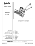
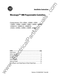
APPLICATIONS
As a Snow Thrower:
• Clears snow from walkways, driveways, sidewalks,
pathways, etc.
Discharge
- Directional
Control
/
Cover Screws (7)
\
\
Vanes
/
/
I
I
ge Lock Nut
Rotor
Belt Case Cove
_'_'_'_Scraper
6
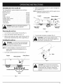
ASSEMBLING
THE COUPLER
2.
The TrimmerPlus® system enables the use of these
optional add-ons.
Blower/Vacuum
..........................
BV720r
Cultivator ...............................
GC720r
Edger ...................................
Hedge Trimmer ...........................
Straight Shaft Trimmer .....................
SweeperlBlower ..........................
Tree Pruner ..............................
LE720r
HS720r
SS725r
SB720r
TP720r
Turbo Blower
TB720r
............................
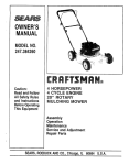
While firmly holding the add-on, push it straight into
the coupler (Fig. 2).
NOTE: Aligning the release button with the guide recess
will help installation (Fig. 1).
Coupler
\
\
Release Button
Primary
Hole
\
\
I
manual for add-on prior to operation.
WARNING: Read and understand operator's
1_,
Removing
the
Upper Shaft
Housing
add-on:
Knob j
Lower Shaft
Housing
Fig. 2
1. Turn the knob counterclockwise to loosen (Fig. 1).
2.
Press and hold the release button (Fig. 1).
3.
Turn the knob clockwise to tighten (Fig. 3).
3. While firmly holding the upper shaft housing, pull the
snow thrower attachment out of the coupler (Fig. 2).
Installing
[,_
the
add-on:
I,_
primary hole (Fig. 2) and securely tighten the
cAuTION:
the release
buttOn in the
knob
before LOck
operating
this unit.
]
and damage to the unit, shut unit off before
WARNING:
avoid serious
removing or TO
installing
add-ons.personal injury
NOTE: To make installing or removing the add-on
easier, place the unit on the ground or on a
work bench.
1. Turn knob counterclockwise
Coupler
'
x\\\\
to loosen (Fig. 1).
Guide Recess
Release Button
\\
\
\\\
\
L
Fig. 3
CAUTION: The snow thrower attachment
with the coupler system is to be used in the
primary hole only. Using the wrong hole
could lead to personal injury or damage to
the unit.
Counterclockwise
Knob
Fig. 1
7
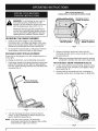
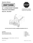
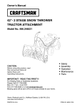
Viewofsnowthrowertop
lookingdownondischarge
directional
control
Discharge snow in
FRONT of operator
WARNING: To aid starting the two-cycle or
four-cycle gasoline powerheads in cold
weather, the unit should be stored in an area
with the temperature above 40"F (4.4 C).
450
//
Refuel and store the gasoline powerhead in
an area free of potential vapor ignition sources
such as open flames (pilot lights) or electrical
sparking devices (switches, electric motors).
OPERATING
//
//
THE SNOW THROWER
Discharge snow to
LEFT of operator
1. Squeeze the power trigger on the powerhead
to start the rotor. The depth and weight of the snow
governs the forward speed. Refer to the operator's
manual of the powerhead for further instructions.
2.
Do not tip the snow thrower to self-propel. Push the
snow thrower so that unit rides on the scraper.
DISCHARGE
//
DIRECTION
Discharge snow to
RIGHT of operator
Fig. 5
3.
ADJUSTMENT
Release discharge directional control into the
discharge direction slot to secure position of snow
throwing desired.
Snow may be discharged to the left, straight forward, or
to the right.
To change the direction, use the following instructions:
NOTE: Make sure discharge directional control is securely
positioned in direction slot and cannot rotate freely.
1.
TIPS FOR BEST SNOW
Firmly grasp handle of discharge directional control and
pull up. This releases the rod, which is spring-loaded,
from the current discharge direction slot and allows free
movement (Fig. 4).
THROWER
4.
For the most efficient snow throwing, keep the vanes
parallel, throw snow downwind, and slightly overlap
each swath (Fig. 6)
5.
Hold the unit by the handle and use a swinging or
sweeping motion when cleaning steps or deep drifts.
I *_ "_ Pull the discharge
/,_ "*
directional control up
Fig. 4
2
Turn the discharge directional control to the left,
center, or right, depending on which direction you
want to throw the snow (Fig. 5).
NOTE: From the center position, the discharge
directional control turns 45 degrees only in either
direction (left or right). Do not force.
Fig. 6
8
RESULTS
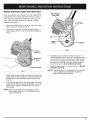
INSPECTING/REPLACING
THE DRIVE BELT
Belt Tensioner
(Idler Arm)
When servicing the snow thrower use only original MTD
replacement parts. Inspect the drive belt once a year or
every 50 hours of operation, whichever comes first, for
wear. If the drive belt needs to be replaced, use the
following instructions.
1.
Remove the flange lock nut from the belt case cover
with a wrench or nut driver (Fig. 7).
2.
Remove the seven (7) screws from the belt case
cover using a #T20 Torx bit or flat blade screwdriver
(Fig. 7).
Drive Pulley
Pulley
Fig. 8
Cover
Screws (7)
.
Belt Cover
Case
Flange Lock Nut
Fig. 7
3.
Pull the belt tensioner (idler arm) away from the drive
pulley. Remove the damaged or broken belt from the
driven pulley and drive pulley inside of the housing
(Fig. 8).
4.
Loop the new belt around the drive pulley and driven
pulley (Fig. 8). Pull the belt tensioner (idler arm) away
from the drive pulley to install the belt around the
drive pulley.
6.
Reinstall the cover with the seven (7) screws. To
make installation easier, place the narrow part of the
cover into the recess of the housing. Install the top
two screws, then push the rest of the cover down
into the recess and over the rotor shaft. Torque all
seven (7) screws to 18-23 in,lb (2.0-2.5 N,m).
Install the flange lock nut. Torque the nut to 80-100
in,lb (9.0-11.2 N,m).
NOTE: If the flange lock nut is damaged, do not replace
it with a standard nut. Replace only with an
original MTD replacement part.
NOTE: Make sure the washer is still in place on the
driven pulley shaft prior to reinstalling the belt
case cover (Fig. 8).
9
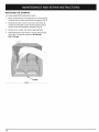
REPLACINGTHE
SCRAPER
Use only original MTD replacement parts.
1.
Place snow thrower on the ground or on work bench.
Position unit so vanes and rotor are facing up (Fig. 9).
2.
Beneath the rotor, locate and remove the three (3)
screws securing the scraper to the housing using a
#T20 Torx bit or flat blade screwdriver (Fig. 9).
3.
Remove the scraper and discard appropriately.
4.
Reinstall the three (3) screws to secure new scraper
to the unit. Torque the screws to 25-30 in,lb
(2.8-3.3 N.m).
10
STORAGE
ACCESSORIES/REPLACEMENT
• Check unit before storage to be sure the equipment is
in safe working condition.
Shoulder Strap ...........................
Scraper ................................
Drive Belt ..............................
• Remove the residue ice or snow from the rotor by
briefly running the unit out of the snow.
PARTS
682075
731-2557
754-0633
Flange Lock Nut ........................
712-3004A
• Stop the engine or motor.
• Store the snow thrower indoors, in a dry and locked
place, out of the reach of children.
Use only original MTD replacement
parts.
• Maintain or replace safety and instruction labels, as
necessary.
For gas powerhead
units:
• Allow the unit to cool before storing in any enclosure.
• Drain fuel from unit. Never store the unit with fuel in the
fuel tank inside a building where ignition sources are
present such as hot water and space heaters, clothes
dryers, etc.
TRANSPORTING
• Allow the unit to cool before transporting.
• Secure the unit while transporting.
For gas powerhead
units:
• Drain fuel from unit.
• Tighten fuel cap before transporting.
Unit Weight (Add-On only) ................................................................
Snow Depth (maximum) .............................................................
Cleared Path Width
...............................................................
9.2 Ibs. (4.17 kg)
6-inches (.152 meters)
12-inches (.305 meters)
11
MANUFACTURER'S
LIMITED WARRANTY FOR:
T
®
The limited warranty set forth below is given by MTD
SOUTHWEST INC ("MTD") with respect with new
merchandise purchased and used in the United States, its
possessions and territories.
MTD warrants this product against defects in material and
workmanship for a period of two (2) years commencing on the
date of original purchase and will, at its option, repair or
replace, free of charge, any part found to be defective in
material or workmanship. This limited warranty shall only apply
if this product has been operated and maintained in
accordance with the Operator's Manual furnished with the
product, and has not been subject to misuse, abuse,
commercial use, neglect, accident, improper maintenance,
alteration, vandalism, theft, fire, water, or damage because of
other peril or natural disaster. Damage resulting from the
installation or use of any accessory or attachment not
approved by MTD for use with the product(s) covered by this
manual will void your warranty as to any resulting damage.
This warranty is limited to ninety (90) days from the date of
original retail purchase for any MTD product that is used for
rental or commercial purposes, or any other incomeproducing purpose.
No implied warranty, including any implied warranty of
merchantability
or fitness for a particular purpose,
applies after the applicable period of express written
warranty above as to the parts as identified. No other
express warranty or guaranty, whether written or oral,
except as mentioned above, given by any person or
entity, including a dealer or retailer, with respect to any
product shall bind MTD. During the period of the
Warranty, the exclusive remedy is repair or replacement
of the product as set forth above. (Some states do not
allow limitations on how long an implied warranty lasts, so
the above limitation may not apply to you.)
The provisions as set forth in this Warranty provide the
sole and exclusive remedy arising from the sales. MTD
shall not be liable for incidental or consequential loss or
damages including, without limitation,
expenses
incurred for substitute or replacement
lawn care
services, for transportation or for related expenses, or
for rental expenses to temporarily replace a warranted
product. (Some states do not allow limitations on how long
an implied warranty lasts, so the above limitation may not
apply to you.)
HOW TO OBTAIN SERVICE: Warranty service is available,
WITH PROOF OF PURCHASE THROUGH YOUR LOCAL
AUTHORIZED SERVICE DEALER. To locate the dealer in your
area, please check for a listing in the Yellow Pages or contact
the Customer Service Department of MTD SOUTHWEST INC
by calling 1-800-345-8746 or writing to 550 N 54th Street,
Chandler, Arizona 85226 or if in Canada call 1-800-668-1238.
No product returned directly to the factory will be accepted
unless prior written permission has been extended by the
Customer Service Department of MTD SOUTHWEST INC.
In no event shall recovery of any kind be greater than the
amount of the purchase price of the product sold. Alteration
of the safety features of the product shall void this Warranty.
You assume the risk and liability for loss, damage, or injury
to
you
and
your
property
and/or
to
others and their property arising out of the use or misuse or
inability to use the product.
This limited warranty does not provide coverage in the
following cases:
How State Law Relates to this Warranty: This warranty
gives you specific legal rights, and you may also have other
rights which vary from state to state.
A. Wear items - Bump Knobs, Outer Spools, Cutting Line,
Inner Reels, Starter Pulley, Starter Ropes, Drive Belts
B.
MTD does not extend any warranty for products sold or
exported outside of the United States of America, its
possessions
and territories, except those sold through
MTD's
authorized
channels
of export
distribution
MTD reserves the right to change or improve the design of
any TrimmerPlus® Product without assuming any obligation
to modify
any product
previously
manufactured.
This limited warranty shall not extend to anyone other than
the original purchaser, original lessee or the person for
whom it was purchased as a gift.
To locate your nearest service dealer dial
1-800-345-8746 in the United States or
1-800-668-I 238 in Canada.
MTD SOUTHWEST
INC
550 N. 54th Street
Chandler, AZ 85226 U.S.A.
SAVE THESE INSTRUCTIONS
FOR FUTURE
FOR QUESTIONS
CALL 1-800-345-8746
OR 1-800-668-1238
IN CANADA
OPERATOR'S MANUAL PART NO. 10415
PRINTED IN U.S.A.
REFERENCE.
IN U.S.
REV. A
8/01