1
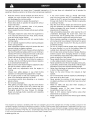
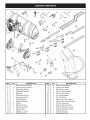
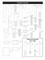
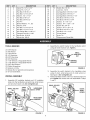
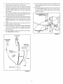
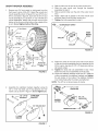
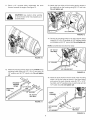
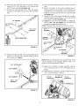
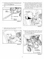
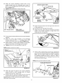
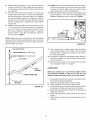
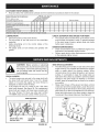
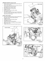
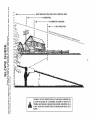
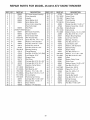
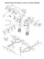
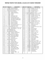
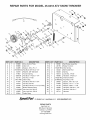
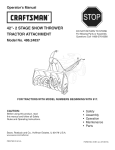
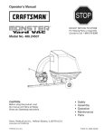
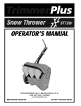
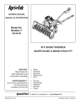
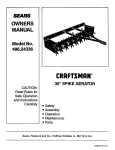
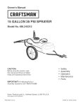
OWNERS
MANUAL
IVlodel No.
45-0418
ATV SNOW THROWER
CAUTION:
Read Rules for
Safe Operation and
Instructions Carefully
AVERTISSEMENT
•
Lire et suivre attentivement
les instructions et
consignes
PRINTED IN U.S.A.
de securit6
o
Safety
Assembly
Operation
Maintenance
Parts
Securite
Assemblage
Utilisation
Entretien
Pieces
FORM NO. 40367 (REV. 2/12/08)
Any powerequipmentcancauseinjuryif operatedimproperlyor if the userdoesnot understandhowto operatethe
equipment.
Exercise
cautionat alltimes,whenusingpowerequipment.
•
Readthisowner'smanualcarefullyandknowhowto
operateyoursnowthrowerandhowto stopthe unit
anddisengage
thecontrolsquickly'.
Neverallowchildrentooperatetheequipment.
Neverallowadultsto operatethe equipmentwithout
properinstruction.
Keepthe area of operationclear of all persons,
especiallysmallchildren,andpets.
Neveroperatethesnowthrowerwithoutgoodvisibility
or light.
Thoroughly
inspectthe areawherethe equipmentis
to be usedandremoveall doormats,sleds,boards,
wiresandotherforeignobjects.
Disengageall clutchesandshift intoneutralbefore
startingengine.
Do notoperateequipment
withoutwearingadequate
winteroutergarments.
Wearsubstantial
footwearwhichwill protectfeetand
improvefootingonslipperysurfaces.
NeveroperatetheATVsnowthrowerwithoutattaching
theclipofthetetheredsafetyswitchtoyourclothing.A
riderlessATVwitha runningsnowthrowercouldcause
seriousinjurytoa fallenoperatororto others.
Checkfuelbeforestartingtheengine.Donotremove
the fuel cap or fill the fueltank whilethe engineis
runningorhot.Donotfillthefueltankindoors.
Gasoline
is anextremely
flammable
fuel.
Makesurethesnowthrowerheightisadjustedtoclear
thetypeofsurfaceitwillbeusedon.
Nevermakeany adjustmentswhile the engineis
running.
Alwayswear safetyglassesor eye shield during
operation
or whileperforming
adjustment
or repair.
Do notplacehandsor feetnearrotatingparts.Keep
clearofthedischarge
openingatalltimes.
Useextremecautionwhenoperatingon or crossing
gravelsurfaces.
Donotcarrypassengers.
Afterstrikinga foreignobject,stopthe snowthrower
andATV,setthe brakeon the ATV,removethe wire
fromthe sparkplugon the snowthrowerandthen
thoroughlyinspectthe snow throwerfor damage.
Repairany damagebeforerestartingandoperating
thesnowthrower.
If the snowthrowerstarts to vibrateabnormally',
stopthe snowthrowerandATVimmediately,
setthe
brakeontheATV,removethesparkplugonthesnow
throwerandcheckforthecause.Vibrationisgenerally
a warningoftrouble.
Stopthe snowthrowerengineandremovethe spark
plugwirewhenever
youleavetheoperatingposition,
beforeunclogging
the snowthroweror makingany
adjustments
or inspections.
Takeall possibleprecautions
whenleavingthe unit
unattended.Disengagethe clutch lever,lowerthe
snowthrower,setthe parkingbrake,turnoffthe ATV
andsnowthrowerenginesandremovethe keys.
Whencleaning,repairingor inspecting,
makecertain
all movingpartshavestopped.Disconnect
the spark
plugwireandkeepit awayfromthe plugto prevent
accidental
starting.
Donot runengineindoorsexceptwhentransporting
the snowthrowerin or out of the building.Openthe
outsidedoors.Exhaustfumesaredangerous.
Donotclearsnowacrossthefaceofslopes.Exercise
extremecautionwhenchangingdirectionon slopes.
Donotattempttoclearsteepslopes.Refertotheslope
guideonpage34ofthismanual.
Neveroperatethesnowthrowerwithoutguards,plates
or othersafetyprotection
devicesinplace.
Neveroperatethesnowthrowernearglassenclosures,
automobiles,
windowwells,dropoffsetc.withoutproper
adjustment
ofthesnowthrowerdischarge
angle.
Neverdirectdischarge
at bystanders
or allowanyone
infrontofthesnowthrower.
Neverrun the snowthrowerinto materialat high
speeds.
Donotoverload
themachinecapacitybyattempting
to
clearsnowattoofasta rate.
Neveroperatethe machineat hightransportspeed
onslipperysurfaces.Lookbehindandusecarewhen
backingup.
Watchfor trafficand stay alert when crossingor
operatingnearroadways.
Disengagepower to the snow thrower when
transporting
or whennotinuse.
Referto ATV owners manualbeforeusing other
attachments
oraccessories.
Neveroperatethesnowthrowerwithoutgoodvisibility
or light.
This document (or manual) is protected under the U.S. Copyright Laws and the copyright laws of foreign countries, pursuant to the
Universal Copyright Convention and the Berne convention. No part of this document may be reproduced or transmitted in any form or by
any means, electronic or mechanical, including photocopying or recording, or by any information storage or retrieval system, without the
express written permission of Agri-Fab, Inc. Unauthorized uses and/or reproductions of this manual will subject such unauthorized user
to civil and criminal penalties as provided by the United States Copyright Laws.
© 2009 Agri-Fab,
Inc.
2
15
\
24
12
25
/
\
3O
\
\
29
27 /
/
28
REF
1
2
3
4
5
6
7
8
9
10
11
12
13
14
15
QTY
1
2
1
2
1
1
1
1
1
2
2
1
1
1
1
DESCRiPTiON
REF
16
17
18
19
20
21
22
23
24
25
26
27
28
29
30
Snow thrower Housing
Housing Anchor Strap
Handlebar Switch
Stabilizer Bracket
Actuator
Outer Mount Strut
Inner Mount Strut
Guide Bracket
Support Bracket
Collar
Mounting Tube
Wheel Assembly
Guide Plate
Spacer, 3" Long
Push Channel
3
QTY
2
2
2
2
2
2
2
1
1
1
2
1
1
1
1
DESCRiPTiON
6-5/8" Clamp Bracket
6-5/8" Strut Mount
6-5/8" Strut Mount
5-1/2" Clamp Bracket
5-1/2" Strut Mount
4" Clamp Bracket
4" Strut Mount
Rear Frame Tube (Bent)
Rear Frame Tube (Straight)
Control Assembly
Polaris Clamp Bracket
Polaris Strut Mount (LH)
Polaris Strut Mount (RH)
Wiring Harness
Discharge Chute
r-T
/
1
/
2
S
/
/
/
7
11
21
O
S
E
3
17
22
/
J
10
23
/
/
/
J
/
/
12
____--1/
13
,-------'-3
-------1
----------1
18
/
/
-------1
/
/
/
-------1
/
/
1
PARTS NOT SHOWN
FULL SiZE
26
I
/
25
/
I
I
I
I
I
I
27
28
29
3O
REF
1
2
3
4
5
6
7
8
9
10
11
12
13
14
15
16
TOOLS
(1)
(1)
(!)
(2)
(2)
(2)
(1)
(1)
(1)
(1)
(1)
(1)
(1)
.
DESCRiPTiON
Clevis Pin, 1/2" x 3-1/2"
Clevis Pin, 1/2" x 2"
Hex Bolt, 5/16-18 x 1"
Hex Bolt, 1/2-13 x 3-1/2"
Washer, 1/2" x 1-1/2"
Hex Bolt, 5/16"x 3"
Hex Bolt, 3/8-16 x 2"
Hair Pin
= REF
17
18
19
20
21
22
23
24
25
26
27
28
29
30
31
32
Bowed Washer, 1" x .32"
Washer, 5/16"
Hex Bolt, 1/2-13 x 2-1/4"
Hex Bolt, 1/2-13 x 1-1/2"
Hex Flange Bolt, 1/4-20 x 1"
i Flanged Lock Nut, 1/4-20
i Nylock Nut, 5/16-18
i Nylock Nut, 3/8-16
NEEDED
.
5/16" Wrench
3/8" Wrench
7/16" Wrench
1/2" Wrenches
9/16" Wrenches
3/4" Wrenches
1-1/6" Wrench or Adjustable Wrench
1-1/8" Wrench or Adjustable Wrench
3/16" Allen Wrench
Phillips Screwdriver
Scissors or Knife
Grease Gun w/general purpose grease
15" Concrete Block
WIRING
.
QTY
3
1
4
4
25
2
4
4
2
10
12
1
6
6
18
4
DESCRiPTiON
Nylock Nut, 1/2-13
Lock Nut, 1/2-13
Carriage Bolt, 5/16-18 x 1-3/4"
Carriage Bolt, 5/16-18 x 1"
Carriage Bolt, 5/16-18 x 1-1/4"
Hex Bolt, 5/16-18 x 1-1/2"
Hex Bolt, 5/16-18 x 1-3/4"
Spacer, .5" x .75"x .5"
Spacer, .81 "x 1.25" x 1.5"
Nylock Nut, 3/4-10
Spacer .75"x 1.25"x .5"
Hex Bolt, 3/4-10 x 7-1/2"
Hex Bolt, 1/2" x 4-1/2"
Chute Keeper
Nylon Tie
Replacement Shear Bolt
Assemble the switch bracket to the handlebar switch
using (2) small whizlock nuts. Tighten.
_7
_
WHIZLOCK
SMALL
___tl_
,,,,.,_
SWITCH
BRACKET
FIGURE 2
3.
4.
Assemble (2) handlebar brackets and (1) handlebar
strap onto the handlebars using (2) long, small screws
and (2) small nylock nuts. Do not tighten yet.
LONG,
SMALL
SCREW
.
_
ASSEMBLY
SMALL NYLOCK
NUT
QTY
19
2
2
2
2
2
4
2
1
1
4
1
2
3
8
2
HANDLEBAR
STRAP
Assemble the switch bracket to the handlebar strap
using (1) short, small screw and (1) small nylock nut.
See figure 3. Do not tighten yet.
Rotate handlebar switch until it is at desired angle and
then tighten the screws and nuts assembled in steps
1 and 3.
SMALL NYLOCK
NUT
_
SMALL
SHORT,
SCREW
HANDLEBAR
BRACKET
FIGURE 1
FIGURE
3
5.
Secure the relay pack near the battery of the ATV or
other location on the ATV out of harms way.
6. Thread the 3 wire lead from the relay pack forward
through the ATV frame on the same side as the handle
bar switch. Avoid threading wire close to moving parts,
hot parts or pinch points. Use 1 or 2 nylon ties to hold
wire in place.
7. Connect the three leads from the handlebar switch into
the three leads from the relay pack matching up the
red, green and black wires. See Figure 4.
8. Thread the bullet connector from the relay pack forward
through the frame and out through the front of the ATV.
Avoid threading wire close to moving parts, hot parts
or pinch points. Use 1 or 2 nylon ties to hold wire in
place.
9. Plug the bullet connector from the relay' pack into the
bullet connector on the actuator.
10. Attach the red wire from the fuse to the positive terminal
on the ATV battery. Attach the negative lead (black
wire) from the relay pack to the negative terminal on
the ATV battery.
11. Use the handlebar switch to fully extend the actuator,
then disconnect the actuator.
12. Attach the tethered safety switch to the handlebar using
(4) pre-assembled screws and (4) pre-assembled nuts.
See figure 5.
13. Thread the wiring through the ATV and out the front of
the ATV. Avoid threading wire close to moving parts,
hot parts or pinch points. Nylon ties can be used to
hold wire in place.
PRE-ASSEMBLED
'_
!
!
I
I
I
I
FIGURE 5
ACTUATOR
BATTERY
--
+
BULLET
CONNECTOR
3=WIRE
LEAD
RED
/
FUSE
RELAY PACK
FIGURE 4
SNOW THROWER
.
ASSEMBLY
Remove any CV boot guard or stick guard from the
front lower A arms of the ATV. Select the correct strut
mount assembly shown in figure 6 for your ATV. If your
ATV is not listed in figure 6, start with the 5-1/2" strut
mount assembly. If you use the 4", 5-1/2" or 6-5/8" strut
mount assemblies, attach with the strut mount on the
bottom of the A arm and the bolts on the outside of the
A arm. Do not tighten
__A
4" Strut
3.
Slide a collar over the end of the outer mount strut.
4.
Slide the outer mount strut through the brackets
assembled in step 2.
Slide a second collar over the end of the outer mount
strut.
Apply a light coat of grease to the inner mount strut
and then insert it into the outer mount strut.
Tighten the bolts assembled in step 2.
5.
6.
7.
bolts at this time.
Mount
OUNT STRUT
_3/8"
x2"
INNER
MOUNT
STRUT
/
COLLAR
COLLAR
FIGURE 8
'
6-5/8" Strut
Mount
6-5/8" Strut
Strut
Mount
\
Mount
3/8" × 2"
-1/2"--4
_I
\
8.
Fasten the ends of the inner and outer mount struts
to the strut mount assemblies that you attached to the
ATV's A-arms. Use two (2) 1/2" x 3" clevis pins and two
(2) hairpin cotters.
9. Tighten the bolts and nuts assembled in step 1 that
fasten the strut mount assemblies to the A-arms.
10. Center the stabilizer brackets under the ATV. Slide the
Bombardier
Out(ander Strut
3/8" × 2"
Mount
\
3/8"
× 2"
FIGURE 6
collars up against the stabilizer brackets and tighten
the set screws in the collars. The stabilizer brackets
must rotate freely after the collars are tightened.
NOTE: The ATV is not shown below for clarity.
.
"------
Assemble the stabilizer brackets together using (2)
1/2" x 4-1/2" hex bolts, (2) 3" long spacers and 1/2"
nylock nuts as shown in figure 7. Do not tighten yet.
/
112"x 4-112"
HEX BOLT
112" x 3-112"
CLEVIS PIN
STABILIZER
BRACKET
J
1/2" x 3"
CLEVIS PIN
HAIRPIN
COTTER
I_"NYLOCK
NUT
HAIRPIN COTTER _
FIGURE 9
3" LONG
SPACER
FIGURE 7
7
11. Placea 15" concreteblock underneaththe snow
thrower,beneaththeengine.Seefigure10.
13.Attachthefrontholesofthe housinganchorstrapsto
theweldboltsonthehousingusing(2) 1/2"locknuts.
Do not tighten
yet.
CAUTION:
Use caution while working
on snow thrower when it is propped up on
concrete block.
112" LOCK NUT
FIGURE 12
14. Secure the mounting tubes to the side support straps
using (2) 1/2" x 2-1/4" hex bolts, (4) 1/2" washers (inside
and outside) and (2) 1/2" nylock nuts. Do not tighten yet.
NOTE: Concrete block not shown for clarity.
112"X 2-114"
HEX BOLT
\
FIGURE 10
I_"WASHER
1/2" NYLOCK NUT
12. Attach the housing anchor straps to the outside of the
mounting tubes using (4) 1/2" x 2-1/4" hex bolts, (8)
1/2" washers and (4) 1/2" nylock nuts. Do not tighten
yet.
HOUSING
ANCHOR
_,_._
/1_/
MOUNT, SA
_J_J
,_,_
FIGURE 13
15. Place the push channel over the ends of the mounting
tubes. Line up the holes as shown in the figure below
and secure the push channel using (2) 1/2" x 3-1/2"
hex bolts, (4) 1/2" washers (one on each side) and (2)
1/2" nylock nuts. Do not tighten yet.
"
/
NUT
1/2" X 2-114"
PUSH
CHANNEL
\
HEX BOLT
FIGURE 11
I/2"NYLOCK
NUT
I_"WASHER
112"x 3-112"
HEX BOLT
FIGURE 14
16. Attachthe bentrearframetubeto the pushchannel
using(2)1/2"x 3-1/2"hexbolts,(4) 1/2"washersand
(2)1/2"nylocknuts.Donot tightenyet.
17. Remove the concrete block from under the engine
and place it underneath the the end of the rear frame
tube.
1/2" WASHER -.y
"" -.
1/2" x 3-1/2"
HEX BOLT
19. Place the wheel assembly behind the engine mounting
base.
20. Fasten the bottom of the anchor brackets (part of
wheel assembly) to the outside of the mounting tubes
using (4) 1/2" x 2-1/4" hex bolts, (4) 1/2" washers (on
inside of mounting tube) and (4) 1/2" nylock nuts. Do
not tighten yet.
21. Fasten the tops of the anchor brackets to the engine
mounting base using (4) 5/16"x 1" hex bolts and (4)
5/16" nylock nuts. Do not tighten yet.
22. Tighten all nuts and bolts assembled in steps 1214 and 18=21. Do not tighten the nuts and bolts
assembled in steps 15-16 at this time.
NOTE: Complete wheel assembly not shown for clarity.
5/16" x 1"
HEX BOLT
REAR FRAME TUBE
NUT
FIGURE 15
112" NYLOCK
NUT
1/2" WASHER
/
112" x 2-114"
HEX BOLT
18. Attach the support bracket to the mounting tubes using
(4) 5/16" x 1-3/4" hex bolts, (8) 5/16" washers and (4)
5/16" nylock nuts. Tighten.
FIGURE 17
NOTE: Before proceeding with next assembly step, make
sure the actuator is fully extended. Refer to step 11 on
page 6 in the Wiring Assembly Section.
5/16" NYLOCK NUT
5/16" WASHER
23. Fasten top of
1/2" x 3" clevis
hairpin.
24. Fasten bottom
1/2" x 2" clevis
/
I_'_
actuator to wheel assembly using (1)
pin, (2) .5" x .75" x .5" spacers and (1)
of actuator to actuator bracket using (1)
pin and (1) hair pin.
la
1/2" x 3"
CLEVIS PIN
/
.5" x .75" x .5"
SPACERS (2)
1/2" x 2"
CLEVIS PIN
5/16" x 1-314"
HEX BOLT
HAIRPINS (2)
FIGURE 16
FIGURE 18
25. Assemblethe guidebracketand guideplateto the
mounting
tubesusing(2)5/16"x3"hexboltsand5/16"
nylocknuts.Donottightenyet.
26. Removetheconcreteblockfromunderthe rearframe
tube.
28. Place the discharge chute (facing forward) onto the
ring. Attach (3) chute keepers (right side up as shown)
to the bottom of the flange using (6) 1/4" x 1" hex flange
bolts and (6) 1/4" flanged lock nuts. Tighten carefully
so that the nuts are snug but do not dig into plastic
chute keepers. Grasp the bottom flange and make
sure the chute turns freely.
5/16" NYLOCK
1/4" x 1" HEX
FLANGE BOLT
_
1
GUIDE
PLATE
I
HEX BOLT
FIGURE 19
FLANGED
FIGURE 21
27. Lightly coat the top of the ring around the discharge
opening with general purpose grease.
29. Attach the control assembly's support strap to the
engine mounting base using (1) 1/2" x 1-1/2" hex bolt,
1/2" washer (on inside of mounting base) and 1/2"
nylock nut. Do not tighten yet.
FIGURE 20
112" WASHER &
112" NYLOCK NUT
112" x 1-112" HEX BOLT
FIGURE
10
22
30. Attachthe controlassembly'ssupporttube to the
weldedbracketbelowthe dischargechuteusing(2)
5/16"x 1-1/4"carriageboltsand(2)5/16"nylocknuts.
SECURE CABLES HERE
TIE
Do not tighten yet.
31. Tighten bolts assembled in steps 29 and 30.
CHUTETILT/<
CONTROL
BOWED_t
WASHER
I
_5/16"NYLOCN
NUT
FIGURE 25
38. Insert the wire harness into the large hole at the front
of the control box.
39. Connect the wire harness to the switch.
5/16" NYLOCK NUTS
5/16" x 1-114"
CARRIAGE BOLTS
FIGURE
40. Using nylon ties, secure the wire harness and clutch
cable to the handle assembly to keep them from
interfering with moving parts.
23
32. Cut the nylon tie that holds the two chute crank brackets
together.
33. Attach the chute crank brackets to the discharge
housing using (2) 5/16" x 1" carriage bolts, 5/16"
washers and 5/16" nylock nuts. Do not tighten yet.
34. Adjust position of chute crank brackets so that spiral
does not rub bottom of discharge chute notches.
35. Tighten bolts and nuts assembled in step 33.
NOTE: Spiral not shown for clarity.
FIGURE 26
5/16" x 1"
CARRIAGE
41. Roll the ATV up behind the snow thrower, keeping the
push channel centered between the stabilizer brackets.
Make sure the guide bracket will slide in between
the stabilizer brackets as shown in figure 27. Keep a
minimum clearance of 3"-4" between the front of the
ATV and the snow thrower.
NOTE: ATV not shown below for clarity.
STABILIZER BRACKETS
,r_o
/
/
GUIDE BRACKET
,/
/
FIGURE 24
36. Attach the chute tilt control to the control assembly
using (2) 5/16" x 1-3/4" carriage bolts, (2) bowed
washers and (2) 5/16" nylock nuts.
37. Using a nylon tie, secure the cables from the chute tilt
control to the support tube as shown in figure 25.
Note: Do not secure the chute tilt control cables in locations
other than the one shown.
FIGURE 27
11
42. Slidetherearframetubein oroutofthepushchannel
to alignit withtheATVhitch.Makesurethe minimum
3"-4"clearance
between
theATVandthesnowthrower
is maintained.
43. If therearframetubedoesnotslidein or outenough
to alignwiththeATVhitch,movethe boltsthatfasten
therearframetubeto thepushchannelto a different
setofholes.(Refertofigure15).Ifalignment
is stillnot
possible,movetheboltsthatfastenthepushchannel
tothemountingtubesto a differentsetofholes.(Refer
tofigure14).
44. AttachtherearframetubetotheATVhitchusinga 3/4"
x 7-1/2"hexbolt,four(4)shortspacers,a longspacer
anda 3/4"nylocknut.Placespacersaboveor below
the hitchas neededto maintainat least1"clearance
withthe bottomof the ATVandadequateclearance
withtheground.Tighten.
45. Tightenthenutsandboltsthatfastenthepushchannel
to themountingtubes,andtherearframetube.Refer
to figures14 and15. Makesurethe mountingtubes
staycenteredwiththeATVwhiletightening.
46. Slidetheguidebracketalongthe mounting
tubesuntil
thefrontedgeis a 1/4"infrontofthefrontedgeofthe
stabilizerbracketsas showninfigure29.Tighten.
NOTE:Replacethebentrearframetubewiththestraight
rearframetubeifthebentrearframetubedoesnotprovide
adequategroundclearanceandthereis extraclearance
withthebottomoftheATV.
O_
0
(_
0
0
FIGURE 29
47. Use a grease gun to apply general purpose grease
to the grease fittings in the wheel hubs and wheel
spindles. Apply until grease is forced out the ends of
the hubs and spindles.
48. Connect the wiring from the tethered safety switch to
the bullet connector on the wire harness for the switch
on the control box.
49. Reconnect the actuator to the handle bar switch that
was unplugged in step 11 on page 6.
CHECKLIST
_"
Before you operate your snow thrower, please review
the following
checklist to help ensure that you will
obtain the best performance from your snow thrower.
REAR FRAME TUBE
I
1.
_
/4" x 7-1/2"
HEX BOLT
2.
3.
4.
FIGURE 28
5.
6.
7.
12
All assembly instructions have been completed with all
bolts and nuts properly tightened.
Check the discharge chute for proper rotation.
Check operation of tilt control for upper chute.
Verify that the wiring is correct for the actuator and that
the actuator will raise and lower the snow thrower.
Check skid shoe adjustment. (Refer to the Service and
Adjustments section.
Check that the tethered safety switch will shut off the
engine.
Check that the wheel hubs and wheel spindles are full
of grease.
KNOWYOUR
SNOWTHROWER
Read this owner's manual and safety rules before operating your snow thrower.
Compare the illustration below with your snow thrower to familiarize yourself with the various controls and their locations.
CHUTE TiLT
HANDLE
LEVER
\
ON/OFF
SWITCH
CRANK
ROD
UPPER CHUTE
LOWER CHUT_'_
SWITCH
_
HANDLE BAR
TETHERED SAFETY
SWITCH
/
SPIRAL AUGERS
R.H. & L.H.
SCRAPER
SKiD SHOE
PLATE
CHUTE TiLT HANDLE -- Pivots the Upper Chute up or
down to control the angle and distance of discharge.
CRANK ROD -- Rotates the Lower and Upper Chutes to
control the direction of discharge.
UPPER AND LOWER DISCHARGE CHUTE -- Controls
direction and height of snow discharge.
SCRAPER PLATE -- Replaceable plate that absorbs
wear and impact from contact with ground.
SKiD SHOE -- Controls amount of clearance between the
scraper plate and the ground.
SPIRAL AUGER, R.H. & L.H. -- Feeds snow to the
impeller fan at the center of the housing.
ON/OFF SWITCH -- Allows snow thrower engine to be
turned off when sitting on ATV.
HANDLE BAR SWITCH -- Raises and lowers the snow
thrower.
TETHERED SAFETY SWITCH -- Turns snow thrower off
when pulled out.
CLUTCH LEVER -- Engages and disengages the spiral
augers.
HOWTO USEYOUR SNOWTHROWER
HOW TO START YOUR SNOW THROWER
Set clutch lever to "DISENGAGED"
CAUTION:
Never
direct discharge
towards bystanders or windows. Do not
allow anyone in front of unit.
=
=
•
BEFORE STARTING
•
=
Use the end of assembly checklist to verify that all
instructions have been properly completed.
Make sure the skid shoes are adjusted to maintain
adequate ground clearance between the snow thrower
and the type of surface to be cleared. (Refer to the
Service and Adjustments section.)
Make sure the ATV engine has the correct oil for winter
operation. Refer to ATV owner's manual.
Attach the pull out plug to the tethered safety switch. The
snow thrower will not run if the plug is not attached.
Set on/off switch on control mount to "ON"
Follow instructions in your Engine Operator's Manual
to start the snow thrower engine, then continue below.
Board your ATV and move clutch lever on control
mount to "ENGAGED" position
HOW TO STOP YOUR SNOW THROWER
Set clutch lever on control mount to "DISENGAGED"
Set on/off switch on control mount to "OFF"
Follow instructions in your Engine Operator's
to finish Stop Engine procedures.
13
Manual
CONTROLLING
SNOWDISCHARGE
• Tocontrolthedirectionsnowis thrown,thedischarge
chutehas180degreesof rotation.Turnthecrankrod
clockwise
torotatethechutetotheright.Turnthecrank
rodcounterclockwise
torotatethechutetotheleft.
• To controlthe distancesnowis thrown,the upper
sectionof the dischargechutepivotsup and down.
Pushforwardonthechutetilthandletopivotthechute
down,decreasingthe distancesnowis thrown.Pull
backon the handleto pivotthe chuteup,increasing
thedistancesnowisthrown.
It is advisable to operate the ATV at a slow ground
speed for safe and efficient snow removal.
In deep, drifted or banked snow it will be necessary to
use slow ground speed. Drive forward into the snow
and allow the spiral auger to clear the snow. Repeat
this method until a path is cleared. On the second
pass, overlap the first enough to allow the snow
thrower to handle the snow without repeated stopping
and starting of forward motion.
In extremely deep snow, raise the snow thrower from
the ground to remove the top layer and drive forward
only until the ATVs front tires reach the uncleared
bottom layer of snow. Depress the ATV's clutch-brake
pedal and allow the spiral auger to clear the snow.
Reverse the ATV and lower the snow thrower to the
RAISINGANDLOWERING
To raise,use the handlebar switchto shortenthe
actuator.
Tolower,usethe handlebar switchto lengthenthe
actuator.
ground. Drive the ATV forward until the snow again
becomes too deep. Repeating this process into and
out of drifts will eventually clear even the deepest of
snow piles.
If the snow thrower becomes clogged with snow or
jammed with a foreign object, disengage the snow
thrower immediately and shut off the ATV and snow
thrower engines. Set the parking break on the ATV and
unclog the snow thrower with a wooden stick before
resuming operation.
REMOVING
SNOW
Snowremovalconditionsvary greatlyfrom light fluffy
snowfallto wet heavysnow.Operatinginstructions
must
beflexibleto fit the conditions
encountered. The operator
must adapt the ATV and snow thrower to depth of snow,
wind direction, temperature and surface conditions.
Before beginning operation, thoroughly inspect the
area of operation and remove all door mats, sleds,
boards, wires and other foreign objects.
DANGER: Shut off engine and disengage
snow thrower before unclogging discharge
chute. Unclog using a wooden stick, not
your hands.
CAUTION: Never operate the ATV snow
thrower without attaching the clip of the
tethered safety switch to your clothing.
A riderless ATV with a running snow
thrower could cause serious injury to a
fallen operator or to others.
OPERATING TIPS
Discharge snow down wind whenever possible.
To help prevent snow from sticking to the snow thrower,
allow the snow thrower to reach outdoor temperature
before using it. A light coat of wax may also be applied
to the inside surface of the snow thrower housing and
discharge chute.
Use tire chains to improve traction if recommended by
your ATV owners manual.
Before the first snowfall, remove all stones, sticks and
other objects which could become hidden by the snow.
Permanent obstacles should be marked for visibility.
Overlap each pass slightly to assure complete snow
removal.
14
CUSTOMER
•
RESPONSIBiLITiES
Read and follow the maintenance schedule and the maintenance procedures listed in this section.
MAINTENANCE
SCHEDULE
Fill in dates as you
complete regular service.
Service Dates
Check for loose fasteners
Check scraper and shoes for wear
Cleaning
Lubrication Section
x
x
x
x
x
x
Check engine oil level
Maintain engine per instructions below and in engine manual.
LUBRICATION
CHECK
Oil all pivot points on the snow thrower.
Oil pivot points of two idler arms on the clutch/idler
assembly.
Apply penetrating oil to the control cables of the
discharge chute.
Fill grease zerks on front wheels and spindles with
grease.
SCRAPER
AND SHOES
FOR WEAR
The scraper plate and skid shoes on the bottom of the
snow thrower are subject to wear. To prevent damage
to the spiral auger housing, replace plate and shoes
before wear is excessive.
ENGINE
MAINTENANCE
Check oil level before each use. Maintain engine oil as
instructed in the separate engine manual.
Perform spark plug or other maintenance as instructed
in the separate engine manual.
SKID SHOE ADJUSTMENT
CAUTION:
Before servicing or adjusting
the snow thrower, shut off snow thrower and
ATV engines, remove the spark plug wire(s),
set the parking brake and remove the key
from the ignition.
The skid shoes are mounted on each side of the spiral
auger housing. They regulate the distance the scraper
plate is raised above the plowing surface. When
removing snow from a gravel driveway or and uneven
surface, it is advisable to keep the scraper plate as
high above the surface as possible to prevent possible
damage to the spiral auger. On blacktop or concrete
surface, keep the scraper plate as close to the surface
as possible.
Raise snow thrower off the ground and place a block
under each end of the scraper plate. Loosen the six hex
nuts securing the skid shoes to the housing. Adjust the
skid shoes up or down and retighten the nuts securely.
Adjust both skid shoes to the same height to keep the
housing and the scraper plate level. See figure 31.
SPIRAL AUGERS
The spiral augers are secured to the auger shaft with
two shear bolts and nylock nuts. If you hit a foreign
object or if ice jams the augers, the snow thrower is
designed so that the bolts will shear.
If the augers will not turn, check to see if the shear
bolts have sheared. See figure 30. Two replacement
shear bolts and nylock nuts have been provided with
the snow thrower. For future use order part number
710-0890A shear bolt and number 47810 nylock nut.
GEAR HOUSING
SHEAR BO_ AND
NYLOCK NUT
/
SCRAPER
PLATE
t
SKiD
SHOE
FIGURE
FIGURE 31
30
15
REMOVING
THEBELT(Figures
•
•
=
=
=
=
•
=
32-35)
Remove the key and disconnect the spark plug wire
from the snow thrower.
Remove the engine pulley cover, the drive cover and
the skid plate from the snow thrower.
Disengage the snow thrower clutch.
Remove the belt from the top pulley.
Engage the clutch.
Remove the belt from the bottom pulley.
Disengage the clutch.
Lift up on the brake assembly and slip the belt between
the brake assembly and bottom pulley to remove the
belt from the snow thrower.
iNSTALLiNG
DRIVE COVER
THE BELT
Lift up on the brake assembly and slip the belt between
the bottom pulley and the brake assembly.
Engage the clutch.
Install the belt around the bottom pulley.
Disengage the clutch.
Install the belt around the top pulley.
Make sure the belt runs inside all of the belt keepers.
Replace the covers.
Replace the key and reconnect the spark plug wire.
FIGURE
33
PULLEY COVER
SKID PLATE
FIGURE 34
FIGURE
L
32
FIGURE
16
35
STORAGE RECOMMENDATIONS
•
Clean the snow thrower thoroughly. Wash off any salt
deposit which may have dried on the thrower and
housing.
Any bare metal that has become exposed should be
painted or coated with a light oil to prevent rust.
Lubricate all pivot and wear areas.
Store in a dry area protected from weather.
PARTS TO REMOVE AT END OF SEASON
Remove the A-arm brackets from the suspension
of the ATV, especially before using your ATV for offroading, trail riding or other activities hard on the
suspension. See the owners manual of your ATV for
more information.
REMOVAL INSTRUCTIONS
Lower the snow thrower to the ground.
Unplug the actuator.
Unplug the tethered safety switch from the wire harness
of the control box switch.
Remove the clevis pins from the strut mount assemblies
attached to the bottom of the ATV's front A arms and
remove the stabilizer assembly from the ATV. (Refer to
figure 9 on page 7.)
Remove the 3/4" x 7-1/2" hex bolt from the rear hitch of
the ATV to complete removal of the snow thrower.
PROBLEM
Spiral augers don't turn
Clogged discharge chute
Snow thrower stalls
Front wheels slide instead of steering
Snow thrower rides up over snow
CAUSE
1. Drive belt too loose
2. Drive belt broken
3. Shear bolts are sheared.
CORRECTION
1. Increase tension on drive belt
1. ATV ground speed too fast
2. Bottom snow is icy or hard packed
1. Decrease ground speed
2. Lower the skid shoes so that front of
skid shoe is lower than the rear
2. Replace drive belt
3. Replace shear bolts
1. ATV ground speed too fast
1. Decrease ground speed
2. ATV throttle set too low
2. Increase to full throttle
3. Raise snow thrower
3. Snow too deep
4. Snow melts during contact with snow 4. Allow snow thrower to cool to outdoor
thrower
temperatur_ before us!ng
1. Object jammed in spiral auger
1. Stop ATV and snow thrower engine,
disengage the snow thrower clutch
and clear the auger
2. Hard or heavy snow
2. Decrease ground speed
1. Not enough traction at front wheels
1. Increase scraper plate clearance by
lowering the skid shoes
2. Snow thrower wheels do not have 2. Fill front grease zerks with grease
until a small amount comes out the
enough lubrication
bottom
17
.,90
o
(n
N,,=
|
|
|
£
|
|
|
Q
0
1:3
g
|
|
o
N,-
L9 Q.2
|
|
|
o
Q,,
,I_
A POWER POLE
|
|
|
W
O
SIGHT AND HOLD THIS LEVEL WITH A VERTICAL TREE
g
|
|
_>
W
|
|
|
|
|
|
|:
N,-
,,,,J
t_
i-
ii-
|
|
|
|
|
|
0
>
o
o
i-
o
o
CAUTION: DO NOT OPERATE YOUR ATV AND SNOW THROWER ON
A SLOPE iN EXCESS OF 10 DEGREES. BE SURE OF YOUR ATV'S
TOWING AND BRAKING CAPABiLiTiES
BEFORE OPERATING ON A
SLOPE. AVOID ANY SUDDEN TURNS OR MANEUVERS WHILE ON A
SLOPE.
(;o
REPAIR PARTS FOR MODEL 45-0418 ATV SNOW THROWER
\
20
I
33
21
16
/
24
16
/14
@
o
60
/
62
16
51
53
59
/®
49
48
19
REPAIR PARTS FOR MODEL 45-0418 ATV SNOW THROWER
REF
1
2
3
4
5
6
QTY
1
1
1
1
1
1
7
8
9
10
11
12
13
14
15
16
17
18
19
20
21
22
23
24
25
26
27
28
29
30
31
32
33
34
35
36
1
1
1
1
1
1
2
27
4
28
3
2
2
6
6
1
2
4
10
1
1
4
4
2
1
1
4
1
5
5
PART NO.
65683
71464
63768
65685
65684
DESCRIPTION
50" Snow thrower Housing
Drive Assembly
Impeller
Spiral Blades (LH)
Spiral Blades (RH)
Drive Control Assembly
(See back page)
65695
Skid Plate
LH358SA-159655AEngine
65697
Belt Guide Assembly
66093
Actuator Bracket
25942
Drive Output Shaft
HA20185
#61 Woodruff Key
715-0114
Spiral Roll Pin, 1/4 x 1-1/2"
43081
Washer, 5/16" Standard
43084
Hex Bolt, 5/16-18 x 1-3/4"
47810
Nylock Nut, 5/16-18
43182
Hex Bolt, 5/16-18 x 3/4"
784-5618
Bearing Housing
47615
Flange Bearing
47630
Hex Bolt, 5/16-18 x 3/4" (Self)
43086
Lock Washer, 5/16"
25940
Scraper Plate
24279
Skid Shoe
43080
Carriage Bolt, 5/16-18 x 3/4"
44326
Carriage Bolt, 5/16-18 x 1"
25937
Gearbox Center Brace
741-0309
Ball Bearing
741-0493A
Split Bearing, 3/4"
736-0188
Washer, .76 x 1.49 x .06
710-0890A
Shear Bolt, 5/16-18 x 1-1/2"
731-1379A
Chute Adapter
705-5226
Reinforcement Chute
44950
Carriage Bolt, 1/4-20 x 3/4"
40504
Elevator Bolt, 1/4-20 x 1"
48015
Nylon Washer
43088
Washer, 1/4" Standard
REF
37
38
39
40
41
42
43
44
45
46
47
48
49
50
51
52
53
54
55
56
57
58
59
60
61
62
63
64
65
66
67
68
69
70
71
72
20
QTY
6
1
1
5
3
6
6
1
1
1
1
1
6
1
6
8
6
1
1
2
2
3
1
1
1
5
4
4
1
1
1
1
2
1
1
1
PART NO.
47189
731-1300C
731-0921
750-0437
731-0851A
49395
47598
784-5594
731-1313C
710-0896
43085
25947
43064
05931
49681
43003
43070
40230
40236
44377
736-0247
710-0627
40585
25960
25961
48840
43001
HA21362
HA23505
43055
49777
40649
43840
66282
40235
43012
DESCRIPTION
Nylock Nut, 1/4-20
Lower Chute
Upper Chute
Pivot Bushing
Chute Keeper
Flange Hex Bolt, 1/4-20 x 1"
Washer Faced Nut, 1/4-20
Cable Bracket
Cable Guide
Washer Screw, 1/4-14 x .625
Hex Bolt, 5/16-18 x 1-1/2"
Engine Mounting Base
Lock Nut, 5/16-18
Bearing, Housing
Hex Bolt, 3/8-16 x 1"
Lock Washer, 3/8"
Washer, 3/8" Standard
Splined Pulley
Engine Pulley
Hex Bolt, 3/8-24 x 1"
Washer, .41 x 1.25 x .156
Hex Bolt, 5/16-24 x 3/4"
V-Belt
Engine Pulley Cover
Drive Cover
Washer Screw, 1/4-20 x 1/2"
Hex Bolt, 3/8-16 x 1"
Nylock Nut, 3/8-16
Clevis Pin, 1/2 x 2"
Hair Pin, 3/32 x 1.8"
Clutch Cable
Handle Bar Switch
Hex Bolt, 5/16-18 x 1-1/4"
Wiring Harness
Module Assembly
Hex Bolt, 1/4-20 x 3/4"
REPAIR PARTS FOR MODEL 45-0418 ATV SNOW THROWER
81
35
\
31
39
/
42
52\
•
20
e
/
53
/
53
/
\
60
53
61
10
62
21
61
REPAIR PARTS FOR MODEL 45-0418 ATV SNOW THROWER
REF
1
2
3
4
5
6
7
8
9
10
11
12
13
14
15
16
17
18
19
20
21
22
23
24
25
26
27
28
29
30
31
32
33
34
35
36
37
38
39
40
41
42
43
44
45
46
47
QTY
1
1
1
2
2
1
2
2
1
1
1
1
1
2
2
2
2
2
18
21
2
2
1
1
1
11
2
1
1
4
1
1
1
2
1
5
5
1
1
2
2
2
4
4
2
4
2
PART NO.
65699
603-0302
684-0061
784-5149
66036
66122
49503
40366
65025
65024
66283
65027
65026
65030
65028
65032
66068
43682
47810
712-3083
44215
44695
720-04039
731-1313C
784-5604A
43081
43064
703-2735A
24393
741-0475
25973
40244
720-0201A
44917
25639
43054
HA21362
43015
HA19445
25921
25963
25932
43063
49832
HA5074
43601
49542
DESCRIPTION
REF
QTY
PART NO.
Crank Rod Support
Chute Tilt Bracket
48
49
2
2
736-0247
43001
Crank Chute Assembly
U-Joint Block
50
51
2
2
43003
49835
Caster Assembly
Wheel Lift Assembly
Wheel
Collar
Outer Mount Strut
Inner Mount Strut
52
53
54
55
56
57
6
29
12
3
4
4
43262
R19172410
HA180183
43020
43084
43850
Tethered Safety Switch
Strut Mount Assembly (LH)
Strut Mount Assembly (RH)
4" Strut Mount
5-1/2" Strut Mount
6-5/8" Strut Mount
6-5/8" Strut Mount
58
59
60
61
62
63
64
2
1
1
4
1
4
1
44326
25922
25923
46526
49362
711-0469
25377
Carriage Bolt, 5/16-18 x 1-1/4"
Nylock Nut, 5/16-18
Nylock Nut, 1/2-13
Carriage Bolt, 5/16-18 x 1-3/4"
Bowed Washer, 1 x .32 x .06
Shift Knob
65
66
67
68
69
70
1
2
4
2
2
1
48911
26228
47630
26424
25928
26038
Cable Guide
Chute Tilt Handle
71
72
3
2
49932
24817
Washer, 5/16" Standard
Lock Nut, 5/16-18
Chute Crank Bracket
Chute Crank Bracket
73
74
75
76
3
1
2
1
43055
40571
46782
45084
Plastic Bushing, 3/8"
Crank Rod
Crank Rod Chute
Crank Knob
77
78
79
80
2
2
1
1
45048
40354
49777
25944
Palnut, 3/8"
Clutch Handle
81
82
2
2
43982
HA3090
Hex Bolt, 3/8-16 x 2"
Nylock Nut, 3/8-16
Hex Nut, 3/8-16
Deflector Lock Spring
Mounting Tube
Side Support Strap
Housing Anchor Strap
Hex Bolt, 5/16-18 x 1"
83
84
85
86
87
88
89
90
2
1
2
1
2
2
2
2
43085
40656
25382
25384PL
25385PL
25388PL
47024
26422
Bushing, 1"
Grease Fitting
Washer, 1.59 x 1 x .06
Spacer
91
92
1
1
26423
26421
22
DESCRIPTION
Washer, .41 x 1.25 x .156
Hex Bolt, 3/8-16 x 1"
Lock Washer, 3/8"
Hex Bolt, 1/2-13 x 6"
Lock Nut, 1/2-13
Washer, .5312 x 1.5 x .1345
Hex Bolt, 1/2-13 x 2-1/4"
Hex Bolt, 1/2-13 x 1-1/2"
Hex Bolt, 5/16-18 x 1-3/4"
Roll Pin, 1/8 x 5/8"
Carriage Bolt, 5/16-18 x 1"
Rear Frame Tube
Push Channel
Hex Bolt, 1/2-13 x 3-1/2"
Hex Bolt, 3/4-10 x 7-1/2"
Spacer, .75 x 1.25 x .5
Spacer, .81 x 1.25 x 1.5
Nylock Nut, 3/4-10
Lift Retainer
Hex Bolt, 5/16-18 x 3/4" (Thd.)
Spacer
Anchor Bracket
Support Strap
Clevis Pin, 1/2" x 3"
Spacer, .5 x .75 x .5
Hair Pin, 3/32 x 1.8
Linear Actuator
Hex Bolt, 5/16-18 x 3"
On-Off Switch
Hex Nut, 15/32-32
Chute Control Cable
Clutch Cable
Cable Strap
Clevis Pin, 1/4 x 5/8"
Hair Cotter Pin, .08 x 1-1/8"
Hex Bolt, 5/16-18 x 1-1/2"
Rear Frame Tube (Straight)
Upper Clamp Bracket
Clamp Bracket, 4"
Clamp Bracket, 5-1/2"
Clamp Bracket, 6-5/8"
Hex Bolt, 1/2" x 4-1/2"
Stabilizer Bracket
Guide Plate
Guide Bracket
REPAIR PARTS FOR MODEL 45-0418 ATV SNOW THROWER
22
21
22
15
24
21
22
\
O
20
29
2
\
15
15
5
\
19
30
13
_,_'_
\
\
(_
22
8
16
20
1
11
\
(_
3
26
\
5
_17
12
29
\
15
5
6
5
4
REF
1
2
3
4
5
6
7
8
9
10
11
12
13
14
15
16
QTY
1
1
1
1
4
1
1
2
1
1
1
1
1
1
7
1
PART NO.
65688
65689
24286
HA180132
43070
47607
1509-90
43178
HAl1496
41576
43015
43768
25946
712-3008
43082
25944
DESCRiPTiON
Drive Control Plate
Idler Arm
REF
17
18
QTY
1
1
PART NO.
65690
49155
Spacer, .38 x .75 x 1
Hex Bolt, 3/8-16 x 2-1/4"
Washer, 3/8" Standard
19
20
21
1
2
2
HA20186
40232
40233
Torsion Spring
Hex Bolt, 1/4-20 x 1-1/4"
Hex Nut, 1/4-20
Idler Pulley
Hex Bolt, 3/8-16 x 1-3/4"
Hex Nut, 3/8-16
Hex Bolt, 3/8-16 x 1-1/2" (full thd.)
Brake Release Strap
Hex Jam Nut, 3/8-16
Hex Lock Nut, 3/8-16
22
23
24
25
26
27
28
29
30
31
4
1
1
2
1
1
1
2
1
2
43013
46699
HA23199
C-9M5732
23625
47605
44125
43062
43001
40741
Cable Strap
REPAIR PARTS
Agri-Fab, Inc.
809 South Hamilton
Sullivan, IL. 61951
217-728-8388
www.agri-fab.com
DESCRiPTiON
Belt Brake Assembly
Brake Trunnion
Idler Spring
Belt Guide Rod
Spring
Lock Nut, 1/4-20
Hex Bolt, 1/4-20 x 2"
Interlock Switch
Pop Rivet, 3/16
Spacer, .38 x .62 x .27
Washer, .411 x 1 x .03
Washer, .625 x 1 x .03
Hex Bolt, 3/8-16 x 1-1/2"
Hex Bolt, 3/8-16 x 1"
Harness
15