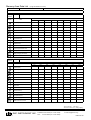
1
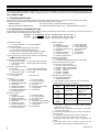
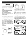
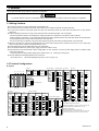
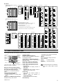
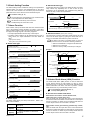
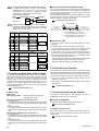
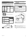
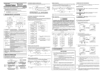
Multi-point Digital Controller MA900/MA901 Instruction Manual IMR01H01-E4 Thank you for purchasing the RKC product. In order to achieve maximum performance and ensure proper operation of your new instrument, carefully read all the instructions in this manual. Please place this manual in a convenient location for easy reference. SYMBOLS WARNING : This mark indicates precautions that must be taken if there is danger of electric shock, fire, etc., which could result in loss of life or injury. CAUTION : This mark indicates that if these precautions and operating procedures are not taken, damage to the instrument may result. ! : This mark indicates that all precautions should be taken for safe usage. : This mark indicates important information on installation, handling and operating procedures. : This mark indicates supplemental information on installation, handling and operating procedures. : This mark indicates where additional information may be located. ! !" This instrument is designed for installation in an enclosed instrumentation panel. All high-voltage connections such as power supply terminals must be enclosed in the instrumentation panel to avoid electric shock by operating personnel. !" All precautions described in this manual should be taken to avoid damage to the instrument or equipment. !" All wiring must be in accordance with local codes and regulations. !" All wiring must be completed before power is turned on to prevent electric shock, instrument failure, or incorrect action. The power must be turned off before repairing work for input break and output failure including replacement of sensor, contactor or SSR, and all wiring must be completed before power is turned on again. !" To prevent instrument damage or failure, protect the power line and the input/output lines from high currents with a protection device such as fuse, circuit breaker, etc. !" Prevent metal fragments or lead wire scraps from falling inside instrument case to avoid electric shock, fire or malfunction. !" Tighten each terminal screw to the specified torque found in the manual to avoid electric shock, fire or malfunction. !" For proper operation of this instrument, provide adequate ventilation for heat dispensation. !" Do not connect wires to unused terminals as this will interfere with proper operation of the instrument. !" Turn off the power supply before cleaning the instrument. !" Do not use a volatile solvent such as paint thinner to clean the instrument. Deformation or discoloration will occur. Use a soft, dry cloth to remove stains from the instrument. !" To avoid damage to instrument display, do not rub with an abrasive material or push front panel with a hard object. !" Do not connect modular connectors to telephone line. WARNING !" An external protection device must be installed if failure of this instrument could result in damage to the instrument, equipment or injury to personnel. !" All wiring must be completed before power is turned on to prevent electric shock, fire or damage to instrument and equipment. !" This instrument must be used in accordance with the specifications to prevent fire or damage to instrument and equipment. !" This instrument is not intended for use in locations subject to flammable or explosive gases. !" Do not touch high-voltage connections such as power supply terminals, etc. to avoid electric shock. !" RKC is not responsible if this instrument is repaired, modified or disassembled by other than factoryapproved personnel. Malfunction can occur and warranty is void under these conditions. NOTICE !" This manual assumes that the reader has a fundamental knowledge of the principles of electricity, process control, computer technology and communications. !" The figures, diagrams and numeric values used in this manual are only for purpose of illustration. !" RKC is not responsible for any damage or injury that is caused as a result of using this instrument, instrument failure or indirect damage. !" Periodic maintenance is required for safe and proper operation of this instrument. Some components have a limited service life, or characteristics that change over time. !" Every effort has been made to ensure accuracy of all information contained herein. RKC makes no warranty expressed or implied, with respect to the accuracy of the information. The information in this manual is subject to change without prior notice. !" No portion of this document may be reprinted, modified, copied, transmitted, digitized, stored, processed or retrieved through any mechanical, electronic, optical or other means without prior written approval from RKC. CAUTION CONTENTS !" This is a Class A instrument. In a domestic environment, this instrument may cause radio interference, in which case the user may be required to take adequate measures. !" This instrument is protected from electric shock by reinforced insulation. Provide reinforced insulation between the wire for the input signal and the wires for instrument power supply, source of power and loads. !" Be sure to provide an appropriate surge control circuit respectively for the following: − If input/output or signal lines within the building are longer than 30 meters. − If input/output or signal lines leave the building, regardless the length. All Rights Reserved, Copyright 2001, RKC INSTRUMENT INC. ® 1. OUTLINE ・・・・・・・・・・・・・・・・・・・・・・・・・・・・・・・・・・・・・・・・ 1 2. MOUNTING ・・・・・・・・・・・・・・・・・・・・・・・・・・・・・・・・・・・・・ 3 3. WIRING ・・・・・・・・・・・・・・・・・・・・・・・・・・・・・・・・・・・・・・・・ 4 4. PARTS DESCRIPTION ・・・・・・・・・・・・・・・・・・・・・・・・・・・ 5 5. SETTING ・・・・・・・・・・・・・・・・・・・・・・・・・・・・・・・・・・・・・・・ 6 6. OPERATION ・・・・・・・・・・・・・・・・・・・・・・・・・・・・・・・・・・・ 14 7. FUNCTIONS ・・・・・・・・・・・・・・・・・・・・・・・・・・・・・・・・・・・ 16 8. ERROR DISPLAYS ・・・・・・・・・・・・・・・・・・・・・・・・・・・・・ 19 9. REMOVING THE INTERNAL ASSEMBLY ・・・・・・・・・・ 19 10. SPECIFICATIONS ・・・・・・・・・・・・・・・・・・・・・・・・・・・・・ 20 RKC INSTRUMENT INC. 1. OUTLINE As a multi-point digital controller of a DIN size 96 × 96 mm, there are MA900 of 4-channel type and MA901 of 8-channel type. This manual describes the specifications, setting, mounting and wiring. For the communication function, see the Communication Instruction #). Manual (IMR01H02-E# 1.1 Checking the Product When unpacking your new instrument, please confirm that the following products are included. If any of the products are missing, damaged, or if your manual is incomplete, please contact RKC sales office or the agent. ! MA900 (MA901): 1 ! Instruction Manual: 1 (IMR01H01-E4) ! Mounting brackets: 2 (Waterproof/dustproof option: 4) ! Mounting screws [with hexagon nuts]: 2 (Waterproof/dustproof option: 4) 1.2 Confirmation of the Model Code Check whether the delivered product is as specified by referring to the following model code list. If the product you received is not the one ordered, please contact RKC sales office or the agent. MA900 - 4 $ $$$ - $ $ - $∗$ $ $ - $ $ / $ / Y MA901 - 8 $ $$$ - $ $ - $∗$ $ $ - $ $ / $ / Y (1) (2) (1) Number of channel 4: 4 channels (MA900) (3) (4) (5) 8: 8 channels (MA901) (2) Control action type F: PID control with autotuning (Reverse action) D: PID control with autotuning (Direct action) W: Heat/cool PID control with autotuning (Water cooling) 1 A: Heat/cool PID control with autotuning (Air cooling) 1 (3) Input type/Input range (This code is common to all channels.) See % Input Range Table (P. 21) 2 (4) Output 1 (OUT1 to OUT4) M: Relay contact output 7: Current output (0 to 20 mA DC) V: Voltage pulse output 8: Current output (4 to 20 mA DC) T: Triac output (5) Output 2 (OUT5 to OUT8) 2 N: No output 7: Current output (0 to 20 mA DC) M: Relay contact output 8: Current output (4 to 20 mA DC) V: Voltage pulse output T: Triac output (6) Power supply voltage 3: 24 V AC/DC (7) Alarm 1 A: B: C: D: E: F: G: H: 4: 100 to 240 V AC 3 Deviation high alarm Deviation low alarm Deviation high/low alarm Band alarm Deviation high alarm 4 Deviation low alarm 4 Deviation high/low alarm 4 Process high alarm J: K: L: M: R: V: W: Process low alarm Process high alarm 4 Process low alarm 4 FAIL alarm Control loop break alarm SV high alarm SV low alarm J: K: L: M: P: S: V: W: Process low alarm Process high alarm 4 Process low alarm 4 FAIL alarm Heater break alarm (CTL6P) 5, 6 Heater break alarm (CTL12) 5, 6 SV high alarm SV low alarm (8) Alarm 2 (option) 3 N: A: B: C: D: E: F: G: H: 2 No alarm Deviation high alarm Deviation low alarm Deviation high/low alarm Band alarm Deviation high alarm 4 Deviation low alarm 4 Deviation high/low alarm 4 Process high alarm (6) (7) (8) (9) (10)(11) (12) (9) Alarm 3 (option) 3 N: No alarm H: A: Deviation high alarm J: B: Deviation low alarm K: C: Deviation high/low alarm L: D: Band alarm M: E: Deviation high alarm 4 V: 4 F: Deviation low alarm W: G: Deviation high/low alarm 4 Process high alarm Process low alarm Process high alarm 4 Process low alarm 4 FAIL alarm SV high alarm SV low alarm (10) Contact input (option) N: No contact input D: Contact input (RUN/STOP, Memory area transfer) (11) Communication Interface (option) N: No communication function 1: RS-232C (RKC communication) 4: RS-422A (RKC communication) 5: RS-485 (RKC communication) 6: RS-485 (Modbus) 7: RS-422A (Modbus) 8: RS-232C (Modbus) (12) Waterproof/dustproof (option) N: No waterproof/dustproof 1: Waterproof/dustproof 1 2 In case of MA901, heat/cool PID action can not be specified. Output assignment of output 1 and output 2: Control action Output 1 (OUT1 to OUT4) Output 2 (OUT5 to OUT8) a, b F or D action type (MA900) Control output (CH1 to CH4) F or D action type (MA901) W or A action type (MA900) Control output (CH1 to CH4) Alarm 3 output (CH1 to CH4) [Option] Control output (CH5 to CH8) Heat-side control output (CH1 to CH4) Cool-side control output (CH1 to CH4) a When the FAIL alarm is specified, the output 2 is not output. FAIL alarm is output from the contact output of alarm 3 (terminal No.51 and 52). b When the alarm 3 is specified as the output 2, output type is only relay contact output. 3 The selection of the alarm action type is common to all channels. 4 With hold action 5 For three-phase heater break alarm, special specified code “Z-168” must be specified at the end of the model code. Three-phase heater break alarm cannot be specified with MA901. 6 If the heater break alarm is selected, contact input and communication function cannot be selected (MA901 only). IMR01H01-E4 2. MOUNTING This chapter describes installation environment, mounting cautions, dimensions and mounting procedures. !"Panel cutout (Unit: mm) Individual mounting 25 Close mounting +0.8 0 L 92 +0.8 0 (2) Avoid the following conditions when selecting the mounting location: • Ambient temperature less than 0 °C or more than 50 °C. • Ambient humidity of less than 45 % or more than 85 % RH. • Rapid changes in ambient temperature which may cause condensation. • Corrosive or inflammable gases. • Direct vibration or shock to the mainframe. • Water, oil, chemicals, vapor or steam splashes. • Excessive dust, salt or iron particles. • Excessive induction noise, static electricity, magnetic fields or noise. • Direct air flow from an air conditioner. • Exposure to direct sunlight. • Excessive heat accumulation. 2.2 Mounting Cautions Take the following points into consideration when mounting this instrument in the panel. • Provide adequate ventilation space so that heat does not build up. • Do not mount this instrument directly above equipment that generates large amount of heat (heaters, transformers, semiconductor functional devices, large-wattage resistors). • If the ambient temperature rises above 50 °C, cool this instrument with a forced air fan, cooler, or the like. However, do not allow cooled air to blow this instrument directly. • In order to improve safety and the immunity to withstand noise, mount this instrument as far away as possible from high voltage equipment, power lines, and rotating machinery. High voltage equipment: Do not mount within the same panel. Power lines: Separate at least 200 mm. Rotating machinery: Separate as far as possible. • Mount this instrument in the horizontal direction for panel. If you did installation except a horizontal direction, this causes malfunction. 2.3 Dimensions !"External dimensions 30 (1) This instrument is intended to be used under the following environmental conditions. (IEC61010-1) [OVERVOLTAGE CATEGORY II, POLLUTION DEGREE 2] 92 92 0 2.1 Mounting Environment +0.8 0 +0.8 " ! WARNING " To prevent electric shock or instrument failure, always turn off the power before mounting or removing the instrument. +0.8 L = 96×n-4 0 n: Number of instruments (2≤n≤6) For mounting of the MA900/MA901, panel thickness must be between 1 to 10 mm. When mounting multiple MA900/MA901s close together, the panel strength should be checked to ensure proper support. If the MA900/MA901s have waterproof/dustproof options, protection will be compromised and not meet IP65 by close mounting. 2.4 Mounting Procedures When the instrument is mounted, always secure with two mounting brackets either top and bottom. The waterproof/dustproof option on the front of the instrument conforms to IP65 when mounted on the panel. For effective waterproof/dustproof, the gasket must be securely placed between instrument and panel without any gap. If gasket is damaged, please contact RKC sales office or the agent. !"Mounting to the panel 1. Prepare the panel cutout as specified in 2.3 Dimensions. 2. Insert the instrument through the panel cutout. 3. Insert the mounting bracket into the mounting groove of the instrument . (Fig.1) 4. Push the mounting bracket forward until the bracket is firmly secured to the panel. (Fig.2) 5. The other mounting bracket should be installed the same way described in 3.and 4. Mounting bracket Fig. 1 Fig. 2 !"Mounting to the panel (When using the mounting screws) In addition, the mounting assembly also include two screws which can be used with the brackets to secure the instrument to the panel. Procedure 1. and 2. are the same as in the above. For the procedure 3. to 6., see the following figures. 3. Mounting bracket 4. (Unit: mm) (2) Insert the mounting screw. 91.8 Mounting bracket Up to 4 mounting brackets can be used. * Rubber (option) 9.2 図3 図4 5. 6. 110.8 91.8 (1) Insert the hexagon nut. 96 96 Insert the L-shaped hook of the mounting bracket into the groove. Pull till click sounds to the direction shown by the arrow. When using the mounting screws, only turn one full revolution after the screw touches the panel. 1* 8.2 100 図5 IMR01H01-E4 図6 3 3. WIRING This chapter describes wiring cautions and terminal configuration. " " ! WARNING To prevent electric shock or instrument failure, do not turn on the power until all the wiring is completed. 3.1 Wiring Cautions For thermocouple input, use the appropriate compensation wire. #" For RTD input, use low resistance lead wire with no difference in resistance between the three lead wires. #" To avoid noise induction, keep input signal wire away from instrument power line, load lines and power lines of other electric #" equipment. If there is electrical noise in the vicinity of the instrument that could affect operation, use a noise filter. #" - Shorten the distance between the twisted power supply wire pitches to achieve the most effective noise reduction. - Always install the noise filter on a grounded panel. Minimize the wiring distance between the noise filter output and the instrument power supply terminals to achieve the most effective noise reduction. - Do not connect fuses or switches to the noise filter output wiring as this will reduce the effectiveness of the noise filter. About four seconds are required as preparation time for contact output every time the instrument is turned on. Use a delay relay #" when the output line is used for an external interlock circuit. Power supply wiring must be twisted and have a low voltage drop. #" For an instrument with 24 V power supply, supply power from a SELV circuit. #" This instrument is not furnished with a power supply switch or fuse. Therefore, if a fuse or power supply switch is required, install #" close to the instrument. Recommended fuse rating: Rated voltage 250 V, Rated current 1 A Use the solderless terminal appropriate to the screw size. #" Screw size: M3×6 Fuse type: Time-lag fuse Recommended tightening torque: 0.4 N・m (4 kgf・cm) 3.2 Terminal Configuration !"MA900 (5) Alarm output (1) Power AC L (5) (6) (8) (9) N (1) (2) (3) 1 2 3 4 5 6 7 8 9 10 11 12 49 50 51 52 53 54 55 56 57 58 59 60 37 38 39 40 41 42 43 44 45 46 47 48 (4) (7) 25 26 27 28 29 30 31 32 33 34 35 36 1 AC L 100-240 V 13 14 15 16 17 18 19 20 21 22 23 24 2 Relay contact + DC 1 24 V 1 ALM2 24 V 2 N NO 2 - 49 (6) Contact input (8) CT input 51 CT1 DI 26 Memory area transfer 27 (Option) (NO: Normally Open) NO Relay contact OUT1 6 - 7 + 7 8 - 8 6 OUT2 41 30 OUT3 + 10 - 11 + 11 12 - 12 - 17 B 17 + - 18 B 18 - 19 A CT5 55 + 55 56 - 56 OUT6 + 58 OUT8 11 SSR 59 + RS-485 RS-422A 44 SG 44 SG 45 T (A) 45 T/R (A) 46 T (B) 46 T/R (B) 56 - 47 R (A) 48 R (B) 58 OUT8 59 60 21 B 21 - 59 60 IN4 + 23 B 23 + - 24 B 24 - TC4 24 (Option) 1 Not isolated between each channel. 2 Relationship between CT input and channel number, see 7.8 Heater Break Alarm (HBA) Function. (P.18) RS-232C 44 SG 3 RTD and voltage inputs: Not isolated between each input channel. 45 SD 4 Input terminals (TC1 to TC4, RTD1 to RTD4, IN1 to IN4) correspond to channel numbers 1 to 4 (CH1 to CH4). 46 RD SSR 60 - RTD4 23 36 57 58 OUT8 + 22 A CT8 55 OUT7 NO 12 54 57 - 20 TC3 21 35 (7) Communication (option) SSR 10 20 B CT7 SSR 57 IN3 + 34 53 OUT6 OUT7 RTD3 20 CT6 OUT5 54 NO OUT4 NO 54 OUT7 9 10 OUT4 IN2 + Triac 53 NO 8 SSR OUT4 + OUT6 7 9 - TC2 18 33 Voltage pulse/ Current OUT5 SSR 6 OUT3 NO 15 31 1 NO SSR 9 53 OUT2 NO OUT3 OUT5 5 SSR OUT2 4 Triac 5 15 B RTD2 17 CT4 DI4 (4) Output 2 (option) + - 42 1 5 + 16 A 32 OUT1 14 TC1 15 29 DI2 NO 43 Voltage pulse/ Current OUT1 14 B CT3 (Option) Relay contact IN1 + 28 DI1 40 DI SET (3) Output 1 Voltage RTD1 14 CT2 52 3 4 RTD 13 A 39 NO Relay contact ALM1 3, 4 25 37 38 (2) Alarm output (9) Input Thermocouple RUN/STOP 50 ALM3 2 IMR01H01-E4 !"MA901 (5) (6) (10) (6) Contact input (5) Alarm output With communication or contact input function Relay contact (9) ALM2 (1) (2) (3) 37 38 39 40 41 42 43 44 45 46 47 48 25 26 27 28 29 30 31 32 33 34 35 36 13 14 15 16 17 18 19 20 21 22 23 24 44 SG 44 SG 37 38 45 T (A) 45 T/R (A) 38 50 51 39 NO T (B) 46 T/R (B) 47 R (A) RS-232C 48 R (B) 44 40 (Option) DI2 41 (7) SD 46 RD (8) (10) + - 15 B 15 - RTD2 17 B 17 + - 18 B 18 - 19 A 43 RTD3 CT5 + 20 CT6 (Option) - (2) (3) 37 38 39 40 41 42 43 44 45 46 47 48 25 26 27 28 29 30 31 32 33 34 35 36 13 14 15 16 17 18 19 20 21 22 23 24 1 2 3 Not isolated between each channel. 23 CT8 21 - IN4 + 23 B 23 + - 24 B 24 - (Option) (10) Input 4 21 B TC4 24 48 RTD and voltage inputs: Not isolated between each input channel. + RTD4 CT7 47 Relationship between CT input and channel number, see 7.8 Heater Break Alarm (HBA) Function. (P.18) 20 22 A 46 49 50 51 52 53 54 55 56 57 58 59 60 1 2 3 4 5 6 7 8 9 10 11 12 (1) IN3 20 B TC3 21 45 (9) IN2 + TC2 18 44 (5) 14 16 A 17 CT4 DI SET With heater break alarm function 14 B CT3 43 IN1 + 40 41 45 Voltage TC1 15 42 DI4 42 (4) 14 39 SG RTD RTD1 CT1 46 DI1 52 3, 4 13 A CT2 Memory area transfer ALM3 (9) Input Thermocouple DI NO 49 50 51 52 53 54 55 56 57 58 59 60 1 2 3 4 5 6 7 8 9 10 11 12 RS-485 RS-422A 37 49 (8) CT input 2 (7) Communication (option) RUN/STOP Input terminals (TC1 to TC8, RTD1 to RTD8, IN1 to IN8) correspond to channel numbers 1 to 8 (CH1 to CH8). 2, 3 Thermocouple RTD Voltage 25 A RTD5 (4) + 26 IN5 26 B 26 + 27 B 27 - TC5 (1) Power AC L (2) Alarm output Relay contact 1 AC L DC + OUT1 3 2 5 NO 4 + OUT5 5 6 OUT2 7 + 7 8 - OUT3 OUT3 9 + 10 11 + 12 + 54 55 - 57 + 30 - 30 B 30 - 31 A RTD7 56 + 57 + 32 IN7 32 B 32 + 33 B 33 - TC7 OUT7 57 59 + 58 - 33 34 A 58 RTD8 OUT8 OUT8 59 59 NO 12 29 SSR 58 11 29 B 55 56 IN6 + TC6 OUT6 OUT7 OUT8 SSR - 54 NO 10 11 NO 12 56 OUT4 29 SSR 9 10 OUT4 - OUT7 SSR RTD6 53 OUT6 55 8 9 28 A OUT5 53 NO OUT3 NO OUT4 54 OUT6 7 8 + Triac SSR 6 - 27 Voltage pulse/ Current OUT5 NO SSR 1 53 OUT2 NO 1 Relay contact OUT1 5 - OUT2 2 2 Triac SSR 6 (NO: Normally Open) 24 V - (4) Output 2 Voltage pulse/ Current OUT1 NO 1 24 V N Relay contact ALM1 100-240 V N (3) Output 1 1 35 - 60 35 B 35 + - 36 B 36 - TC8 SSR 60 IN8 + 60 36 4. PARTS DESCRIPTION This chapter describes various display units and the key functions. Channel (CH) display Memory area display CH PV AREA SV Indication lamp Channel key OUT1 OUT2 OUT3 Measured value (PV) display Set value (SV) display OUT4 OUT5 AT CH SET R/S OUT6 OUT7 OUT8 ALM1 ALM2 ALM3 UP key MA900 Set key DOWN key Shift & R/S key (The above figure is MA900. The figure of MA901 is the same as a MA900.) Measured value (PV) display [Green] Displays PV or various parameter symbols. Set value (SV) display [Orange] Displays SV or various parameter set value. Channel (CH) display [Green] • Displays channel number. • Displays character “A” showing batch setting. Memory area (AREA) display [Orange] Displays memory area number. IMR01H01-E4 Indication lamps: Autotuning (AT) lamp [Green] Flashes with the autotuning activated the displayed channel. Output (OUT1 to OUT8) lamp [Green] Lights when the output corresponding each lamp is ON. Alarm lamp * (ALM1 to ALM3) [Red] ALM1: Lights when alarm1 is turned on. ALM2: Lights when alarm2 is turned on. ALM3: Lights when alarm3 is turned on. *Bright lighting: Indicates that the display channel alarm state. Dim lighting: Indicates that other channel except display channel is alarm state. • Shift digits when settings are changed. • Selects the RUN/STOP. in to Set key Used for parameter calling up and set value registration. Increase numerals. Up key Decrease numerals DOWN key The avoid damage to the instrument, is never use a sharp object to press keys. a Channel key • Used when the channel number is changed. • Used to display the character “A” showing batch setting. • Used for start/stop of scan display. Shift & R/S key 5 5. SETTING This chapter describes the operation flowchart of mode and the setting item of each mode. This instrument classes setting item in four kinds of mode. The mode can be selected by pressing the SET or <R/S key. 5.1 Operation Flowchart of Mode • Regardless of the display time of the input type or input range, control starts about 4 seconds after the power is turned on. • If the key is not pressed for more than one minute, the display will automatically return to the PV/SV monitor mode. • If the function is not selected for all of the channels, that parameter symbol is not displayed. • In case of MA901, parameter symbols of the following are not displayed; Current transformer 2 monitor, cool-side proportional band, overlap/deadband, heater break alarm 2, cool-side proportioning cycle time Power ON Input type/Input range Display* Diplay changes automatically Press the <R/S key while pressing the SET key. Press the SET key for 2 seconds. Parameter Setting Mode (P. 10) PV/SV Monitor Mode (P. 7) Measured value (PV) Setup Setting Mode (P. 8) Control loop break alarm RUN state LbA Set value (SV) Autotuning (AT) ATU SET key Press the <R/S key for 1 second. Heater break alarm 1 * Control loop break alarm deadband HbA1 Lbd SET key STOP state Set value (SV) HbA2 AL1 SET key Heater break alarm 2 * Alarm 1 Press the SET key SET key SET key SET key PV bias * Alarm 2 SV Setting & CT Monitor Mode (P. 7) AL2 SET key Set value (SV) setting SV Alarm 3 Press the <R/S key while pressing the SET key. SET key AL3 T SET key Current transformer 1 monitor CT1 SET key CT2 I SET key Derivative time SET key To PV/SV monitor mode d t Press the SET key for 2 seconds. Add Anti-reset windup bPS Input type/Input Range Display CH PV AREA Symbol SV Pc PV AREA SV Input type symbol (SeeTable) bIT InT Scan interval time SCAn Setting changing rate limiter Input range low SVrL SET key LCK1 Used/unused of channels Thermocouple R S B E T N PL II W5Re/ W26Re U L CH E SET key SET key Lock level 1 Symbol K J SET key SET key Input range high Input Type SET key Interval time Overlap/deadband db Input Type Symbol Table SET key SET key Engineering unit (Voltage input: No display) CH SET key Data bit configuration SET key Cool-side proportional band SET key Communication speed SET key Ar SET key Device address * This instrument displays input type code and input range just after power supply ON by each 2 seconds. SET key Cool-side proportioning cycle time * Integral time SET key Current transformer 2 monitor dF Proportioning cycle time * Proportional band P SET key Digital filter * SET key Memory area transfer ArE Pb SET key Lock level 2 LCK2 SET key Symbol Input Type RTD JPt 100 Pt 100 Voltage : Setting item for memory area function * Set the parameter for each channel. : These items are not displayed with MA901. 6 IMR01H01-E4 5.2 PV/SV Monitor Mode PV/SV monitor mode can confirm the measured value (PV) and the set value (SV). Usually, set to this mode during control execution. For checking the measured value (PV) and set value (SV) during operation, the following two methods are available. Checking PV and SV corresponding to each channel !" In PV/SV monitor mode, the PV and SV corresponding to the displayed channel can be checked. Each time the CH key is pressed, the SV corresponding to each channel within the memory area (hereinafter called “control area”) used for control can be checked for each channel. Display example: PV/SV monitor mode display Indicates that PV/SV now on display corresponds to channel 1 within control area 1. Indicates that memory area number 1 is selected as a control area. CH PV AREA SV Indicates that PV corresponding to channel 1 within the control area is 300 °C Indicates that PV corresponding to channel 1 within the control area is 350 °C. When the setting change rate limiter is set, a condition in which the set value (SV) goes changing according to that rate of change is displayed. If the instrument needs to be switched to RUN or STOP mode, press the <RS key in PV/SV monitor mode. In addition, RUN/STOP can be selected by key operation or by open or closed contact input (option). 6.3 Transfer of RUN/STOP (P. 14) Checking SV corresponding to all of the channels within the control area !" The SV corresponding to all the channels within the control area are automatically checked at each scan interval time. 5.4 Setup Setting Mode (P. 8), 7.5 Scan Display Function (P. 16) 5.3 SV Setting & CT Monitor Mode SV setting & CT monitor mode is used to set the set value (SV) and control area or to monitor the current value (current transformer 1, current transformer 2). Press the SET key with state of PV/SV monitor mode to shift to this mode. The UP, DOWN or <R/S key is used to change the numeric value, and the SET key is used to change the parameter as well as to register the numeric value. !"Description of each parameter Set value (SV) setting CH PV AREA SV Set the set value (SV) which is the desired value for control. Setting range: Within input range Factory set value: Temperature input 0 °C [°F] or 0.0 °C [°F] Voltage input 0.0 % • Up to eight memories per channel can be set with one set value (SV) assumed to be one memory. • The set values (SV) corresponding to all of the channels within the same control area can be simultaneously set as the same value. • No setting can be changed when “1 (Lock)” is selected by the lock level 1. Memory area transfer CH PV AREA SV Selects the memory area used for control (Hereafter called the control area). Setting range: 1 to 8 Factory set value: 1 • No setting can be changed when “1 (Lock)” is selected by the lock level 2. • One set value (SV) and up to eight setting items of the parameter setting mode per channel can be stored. For details of the setting items of parameter setting mode, see 5.5 Parameter Setting Mode. (P. 10) Current transformer 1 monitor CH PV Displays the input value of the current transformer 1 used when the instrument is provided with the heater break alarm 1. AREA SV Display range: 0.0 to 100.0 A (Option) • Not displayed when this instrument is not provided with the heater break alarm 1 function. • Displays the input value of the current transformer 1 used when the instrument is provided with the heater break alarm 2 (Z-168). Current transformer 2 monitor [ Correspond to only MA900] CH PV Displays the input value of the current transformer 2 used when the instrument is provided with the heater break alarm 2 (Z-168). AREA SV Display range: 0.0 to 100.0 A (Option) • Not displayed when this instrument is not provided with the heater break alarm 2 function. • In case of MA901, this monitoring screen is not provided. To PV/SV monitor mode IMR01H01-E4 7 5.4 Setup Setting Mode Setup setting mode is used to set the heater beak alarms, PV bias, digital filter, communication, and to lock the set data. The instrument can be switched to AT start or AT cancel. Press the <R/S key while pressing the SET key with state of PV/SV monitor mode, SV setting & CT monitor mode, or parameter setting mode to shift to this mode. The UP, DOWN or <R/S key is used to change the numeric value, and the SET key is used to change the parameter as well as to register the numeric value. !"Description of each parameter Execution of autotuning (AT) CH PV The AT function is executed to the control area now in operation. Setting range: ON: AT start or execution OFF: AT end or cancel AREA SV Factory set value: OFF • The batch setting allows the autotuning to be executed simultaneously in all channels. • When instrument displays data without a channel, an AT lamp does not flash during AT execution. Heater break alarm 1 (HBA1) CH PV HBA1 set value is set by referring to monitor value from the current transformer 1. Used for single-phase or three-phase. AREA SV Displayed only for when the heater break alarm is selected as alarm 2. Setting range: 0.0 to 100.0 A OFF: HBA1 function OFF Factory set value: OFF (Option) • • • • No setting can be changed when “1 (Lock)” is selected by the lock level 1. HBA is not available on a current output. Set HBA1 set value to a value about 85 % of current transformer 1 input value. When power supply variations are large, set the HBA1 set value to a slightly smaller value. In addition, when two or more heaters are connected in parallel, set the HBA1 set value to a slightly larger value so that it is activated even with only one heater broken (However, within the value of current transformer 1). • When no current transformer is connected in any setting other than “OFF,” the heater break alarm is turned on. Heater break alarm 2 (HBA2) [Correspond to only MA900] CH PV HBA2 set value is set by referring to monitor value from the current transformer 2. Used only for threephase. Displayed only for when the heater break alarm (Z-168) is selected as alarm 2. AREA SV Setting range: 0.0 to 100.0 A OFF: HBA2 function OFF Factory set value: OFF (Option) • • • • No setting can be changed when “1 (Lock)” is selected by the lock level 1. HBA is not available on a current output. Set HBA2 set value to a value about 85 % of current transformer 2 input value. When power supply variations are large, set the HBA2 set value to a slightly smaller value. In addition, when two or more heaters are connected in parallel, set the HBA2 set value to a slightly larger value so that it is activated even with only one heater broken (However, within the value of current transformer 2). • When no current transformer is connected in any setting other than “OFF,” the heater break alarm is turned on. • In case of MA901, this setting item is not provided. PV bias CH PV AREA SV Set the PV bias to add to measured value for sensor correction, etc. The PV bias is used to correct the individual variations in the sensors or when there is difference between the measured values (PV) of other instruments. Setting range: -span to +span (Within -1999 to +9999 digits) Factory set value: Temperature input 0 °C [°F] or 0.0 °C [°F] Voltage input 0.0 % No setting can be changed when “1 (Lock)” is selected by the lock level 1. Digital filter CH PV AREA SV Set the time of the first-order lag filter which rejects any noise contained in the measured input. Setting range: 1 to 100 seconds OFF: Digital filter function OFF Factory set value: OFF No setting can be changed when “1 (Lock)” is selected by the lock level 1. Proportional cycle time CH PV AREA SV Set control output cycle. For heat/cool PID action: Heat-side proportional cycle time Setting range: 1 to 100 seconds Factory set value: Relay contact output 20 seconds Voltage pulse output, triac output 2 seconds • No setting can be changed when “1 (Lock)” is selected by the lock level 1. • Not displayed for current output. (A) 8 Continued on the next page. IMR01H01-E4 Continued from the previous page. (A) Cool-side proportional cycle time [Correspond to only MA900] CH PV Displayed only for heat/cool PID control. Set the cool-side control output cycle for the heat/cool PID control. AREA SV Setting range: 1 to 100 seconds Factory set value: Relay contact output 20 seconds Voltage pulse output, triac output 2 seconds • No setting can be changed when “1 (Lock)” is selected by the lock level 1. • Not displayed for current output. • In case of MA901, this setting item is not provided. Device address (Slave address) Communication speed Data bit configuration Interval time CH PV CH PV CH PV CH PV AREA SV AREA SV AREA SV AREA SV These parameter is displayed when the communication function is provided. For details, see the Communication Instruction Manual (IMR01H02-E# #). Scan interval time CH PV AREA SV Sets the time until changed to the next screen when scan-displayed. Setting range: 1 to 10 seconds Factory set value: 2 seconds • No setting can be changed when “1 (Lock)” is selected by the lock level 1. • Only the relevant parameter corresponding to the cannel set to “MonI” or “ConT” in “used/unused channels” of the parameter setting mode can be scan-displayed. Lock level 1 CH PV AREA SV (4) (3) (2) (1) Set to the control area now in operation to restrict parameter setting changes by the key operation. Setting range: (1) Items other than SV and alarms (ALM1 to ALM3) 0: Unlock 1: Lock (2) Alarms (ALM1 to ALM3) 0: Unlock 1: Lock (3) SV 0: Unlock 1: Lock (4) No setting (“0” Fixed) Factory set value: 0000 The lock level 1 can be changed even when the whole set data is locked. Lock level 2 CH PV AREA SV (4) (3) (2) (1) Set to the control area now in operation to restrict RUN/STOP and memory area changes. Setting range: (1) RUN/STOP transfer 0: Unlock 1: Lock (2) Memory area transfer 0: Unlock 1: Lock (3) No setting (“0” Fixed) (4) No setting (“0” Fixed) Factory set value: 0000 The lock level 2 can be changed even when the whole set data is locked. Return to first parameter “Execution of autotuning (AT)” IMR01H01-E4 9 5.5 Parameter Setting Mode The parameter setting mode is used to set various settings relating to control, to change various alarm settings and also to set the setting change rate limiter and used/unused channels. Setting items belonging to the parameter setting mode correspond to the multi-memory area functions and can be stored up to eight memories. Press the SET key for 2 seconds with state of PV/SV monitor mode, SV setting & CT monitor mode, or setup setting mode to shift to this mode. The UP, DOWN or <R/S key is used to change the numeric value, and the SET key is used to change the parameter as well as to register the numeric value. !"Description of each parameter Control loop break alarm (LBA) CH PV Monitors measured value variations and also sets the time to detect any abnormal control loop. Displayed only for when the LBA is selected as alarm 1. AREA SV Setting range: 0.1 to 200.0 minutes OFF: LBA function OFF Factory set value: 8.0 minutes • No setting can be changed when “1 (Lock)” is selected by the lock level 1. • We recommend that the set value of LBA be twice the value of the integral time (I). If the autotuning function is used, the LBA setting time twice as large as the integral time is automatically set. Control loop break alarm deadband (LBD) CH PV Set the area of not outputting LBA. Displayed only for when the LBA is selected as alarm 1. Setting range: 0 to span (0: LBD OFF) AREA SV Factory set value: Temperature input 0 °C [°F] or 0.0 °C [°F] Voltage input 0.0 % • No setting can be changed when “1 (Lock)” is selected by the lock level 1. Alarm 1 (ALM1) CH PV AREA SV Set the ALM1 set value. Displayed when any one of the deviation, process and SV alarms is selected as the alarm 1. Setting range: Process alarm, SV alarm: Same as input range Deviation alarm: -span to +span (Within -1999 to +9999 digits) Factory set value: Temperature input 50 °C [°F] or 50.0 °C [°F] Voltage input 5.0 % • No setting can be changed when “1 (Lock)” is selected by the lock level 1. • Not displayed when FAIL alarm or control loop break alarm is selected for alarm 1. Alarm 2 (ALM2) CH PV AREA SV (Option) Set the ALM2 set value. Displayed when any one of the deviation, process and SV alarms is selected as the alarm 2. Setting range: Process alarm, SV alarm: Same as input range Deviation alarm: -span to +span (Within -1999 to +9999 digits) Factory set value: Temperature input 50 °C [°F] or 50.0 °C [°F] Voltage input 5.0 % • No setting can be changed when “1 (Lock)” is selected by the lock level 1. • Not displayed when FAIL alarm or heater break alarm is selected for alarm 2. Alarm 3 (ALM3) CH PV AREA SV (Option) Set the ALM3 set value. Displayed when any one of the deviation, process and SV alarms is selected as the alarm 3. Setting range: Process alarm, SV alarm: Same as input range Deviation alarm: -span to +span (Within -1999 to +9999 digits) Factory set value: Temperature input 50 °C [°F] or 50.0 °C [°F] Voltage input 5.0 % • No setting can be changed when “1 (Lock)” is selected by the lock level 1. • Not displayed when FAIL alarm is selected for alarm 3. Proportional band (P) CH PV AREA SV Set the proportional band for the P control, PI control or PD control. For heat/cool PID action: Proportional band setting on the heat-side. Setting range: 0 (0.0) to span (However, 9999 digits or less) Factory set value: Temperature input 30 °C [°F] or 30.0 °C [°F] Voltage input 3.0 % • No setting can be changed when “1 (Lock)” is selected by the lock level 1. • ON/OFF action when set to 0 (0.0). Integral time (I) CH PV AREA SV Set the time of integral action which eliminates the offset occurring in proportional control. Setting range: 1 to 3600 seconds OFF (0 second): Integral action OFF (PD action) Factory set value: 240 seconds No setting can be changed when “1 (Lock)” is selected by the lock level 1. (A) 10 Continued on the next page. IMR01H01-E4 Continued from the previous page. (A) Derivative time (D) CH PV AREA SV Set the time of derivative action which prevents ripples by predicting output changes and thus improves control stability. Setting range: 1 to 3600 seconds OFF (0 second): Derivative action OFF (PI action) Factory set value: 60 seconds No setting can be changed when “1 (Lock)” is selected by the lock level 1. Anti-reset windup CH PV AREA SV In order to prevent an overshoot caused by the integral effect, sets the value to restrict the effective range of integral action. Setting range: 0 to 100 % of proportional band (0: Integral action OFF) Factory set value: 100 % No setting can be changed when “1 (Lock)” is selected by the lock level 1. Cool-side proportional band [Correspond to only MA900] CH PV Displayed only for heat/cool PID control. Set the cool-side proportional band for the heat/cool PID control. AREA SV Setting range: 1 to 1000 % of heat-side proportional band Factory set value: 100 % • No setting can be changed when “1 (Lock)” is selected by the lock level 1. • In case of MA901, this setting item is not provided. Overlap/deadband [Correspond to only MA900] CH PV Displayed only for heat/cool PID control. Set the deadband between the heat-side proportional band and the cool-side proportional band. AREA SV Setting range: -span to +span (Within -1999 to +9999 digits) Factory set value: Temperature input 0 °C [°F] or 0.0 °C [°F] Voltage input 0.0 % • No setting can be changed when “1 (Lock)” is selected by the lock level 1. • In case of MA901, this setting item is not provided. • Minus (-) setting results in overlap. Manipulated output (MV) Heat-side proportional band Cool-side proportional band 100 % Cool-side output value Heat-side output value 0% Temperature SV (In proportional control) OL DB OL: Overlap DB: Deadband Setting change rate limiter CH PV Set the amount of set value (SV) change per 1 minute when the SV is changed. Setting range: 0 (0.1) to span/min. OFF: Setting change rate limiter OFF AREA SV Factory set value: OFF • No setting can be changed when “1 (Lock)” is selected by the lock level 1. • The set value (SV) while the setting change rate limiter can be checked in PV/SV monitor mode. • When the power is turned on or the operation is changed from STOP to RUN, the setting change rate limiter functions toward the set value (SV) from the measured value (PV) when started. • If the autotuning (AT) function is activated while the setting change rate limiter functions, PID control continues until the limiter completes its functioning, and the AT function is activated after the limiter completes its functioning. Used/unused of channels CH PV AREA SV Select the used or unused of each channel for each memory area. Setting range: (oFF): Unused (MonI): Used for only alarm (ConT): Used for control and alarm Factory set value: ConT • No setting can be changed when “1 (Lock)” is selected by the lock level 1. • During display scanning, each unused channel is skipped. When the channel number is selected by the CH key, any unused channel is displayed. Return to first parameter setting item. IMR01H01-E4 11 5.6 Setting Procedure 5.6.1 Usual setting (Setting for each channel) Some examples of changing the set value (SV) are described in the following. The same setting procedure applies when other parameters are also set. When the SV is changed !" When CH1 set value (SV) of the control area 1 is change from 0 °C to 300 °C: 1. Press the SET key in PV/SV monitor CH mode state to transfer to SV setting & CT monitor mode. AREA 2. Press the <R/S key to light brightly the hundreds digit. The brightly lit digit indicates which digit can be set. PV SV CH PV AREA SV Every time the <R/S key is pressed, Bright lighting the brightly AREA SV lit digit moves as follows. When another area set value (SV) is changed without !" changing control area When changing the set value (SV) corresponding to channel 2 in memory area 3 from 150 °C to 100 °C with the memory area set to memory area 1: 1. Press the SET key in PV/SV monitor CH mode state to transfer to SV setting & CT monitor mode. AREA 2. Press the <R/S key to light brightly the AREA display. The brightly lit digit indicates which digit can be set. CH PV AREA SV 3. Press the UP key to change to 3. CH 4. Press the SET key to register the value thus set. The display changes to the next parameter (Memory area transfer display). AREA SV CH PV AREA SV Bright lighting Every time the <R/S key is pressed, the brightly lit digit moves as follows. AREA PV SV CH 3. Press the UP key to change to 3. The SV display shows the channel 1 set value (SV) of the memory area AREA number 3. Also, the number of AREA display flashes. PV 4. Press the CH key to change to 2. The SV display shows the channel 2 set value (SV) of the memory area number 3. CH PV AREA SV SV Flashing PV SV Flashing The following is also available when changing the set value. 5. Press the DOWN key to change to 0 in the tens digit. CH PV AREA SV Set value increase (When 199 °C is changed to 200 °C): !" 1. Press the <R/S key to light brightly the least significant digit. 2. Press the UP key to change to 0. The display changes to 200. PV PV SV SV Set value decrease (When 200 °C is changed to 190 °C): !" 1. Press the <R/S key to light brightly the tens digit. 2. Press the DOWN key to change to 9. The display changes to 190. PV PV SV SV Minus (-) value setting (When 200 °C is changed to -100 °C): !" 1. Press the <R/S key to light brightly the hundreds digit. 2. Press the DOWN key (three times) to change to -1. The display changes to -100. 12 PV PV SV SV Flashing 6. Press the SET key to register the value thus set. The display changes to the next parameter (Memory area transfer display). CH PV AREA SV The changed set value is registered by pressing the SET key or also at the time when any of the following key operations is performed. • When the channel number is changed by the CH key • When the memory area number is changed IMR01H01-E4 5.6.2 Batch setting (All channels batch setting) The parameters selected from one memory area and corresponding to all of the channels can be simultaneously set as the same value. The set values (SV) as well as the parameters set for each channel can be simultaneously set. Some examples of changing the set value (SV) simultaneously are described in the following. The same setting procedure applies when other parameters for each channel are also set. When the SV is changed in batch setting !" When all set value (SV) of the control area (memory area 1) is change from 0 °C to 300 °C: The set values (SV) in other memory areas are !" simultaneously set to the same value without changing the control area When changing the set values (SV) corresponding to all of the channels in memory area 2 from 0 °C to 300 °C with the control area corresponding to memory area 1: 1. Press the SET key in PV/SV monitor CH mode state to transfer to SV setting & AREA CT monitor mode. PV 2. Press the CH key. Display the character A on the CH display and “----“ on the SV display. The character A indicates that the batch setting. CH PV AREA SV SV Every time the CH key is pressed, the channel number changes as follows. 3. Press the <R/S key to light brightly the hundreds digit. CH PV AREA SV 1. Press the SET key in PV/SV monitor CH mode state to transfer to SV setting & AREA CT monitor mode. PV 2. Press the CH key. Display the character A on the CH display and “----“ on the SV display. The character A indicates that the batch setting. CH PV AREA SV Every time the CH key is pressed, the channel number changes as follows. 3. Press the <R/S key to light brightly the AREA display. CH PV AREA SV Bright lighting Bright lighting 4. Press the UP key to change to 3. CH PV AREA SV SV 4. Press the UP key to change to 2. The number of AREA display flashes. CH PV AREA SV Flashing 5. Press the SET key. The value thus set is registered simultaneously for all of the channels. The display changes to the next parameter (Memory area transfer). CH PV AREA SV 5. Press the <R/S key to light brightly the hundreds digit. CH PV AREA SV Bright lighting 6. Press the UP key to change to 3. 7. Press the SET key. The value thus set is registered simultaneously for all of the channels. The display changes to the next parameter (Memory area transfer). CH PV AREA SV CH PV AREA SV The set value (SV) corresponding to any unused channel is also subjected to the batch setting. For details of shifting, see page 12. IMR01H01-E4 13 6. OPERATION This chapter describes instrument operation, the instrument operation, RUN/STOP transfer, and control area transfer, etc. 6.1 Power ON When the contact input state is RUN RUN/STOP can be selected by key operation. After power on, this instrument starts control in about 4 seconds. mode, : Only key operation is in the STOP mode. : Only contact input is in the STOP mode. : Both key operation and contact input are in the STOP mode. When a power failure of more than 30 ms occurs, the instrument assumes that the power has been turned off. When power return, the instrument performs the same operation as that at the time of power on. Conditions when changed to STOP mode: • Control: • Alarm: • AT: 6.2 Change of the Set Value (SV) • To change the set value (SV) , set the instrument to SV setting & CT monitor mode. 5.1 Operation Flowchart of Mode (P. 6), 5.6 Setting Procedure (P. 12) • The set values (SV) corresponding to all of the channels within the same control area can be simultaneously set as the same value. 5.6.2 Batch setting (P. 13) OFF OFF Cancel (The PID constants are not updated) RUN/STOP transfer by key operation $" When changing RUN to STOP in the state without RUN/STOP transfer by contact input. CH PV AREA SV • The set values (SV) in other memory areas can be changed without changing the control area. 1. Press the <R/S key for 1 second in PV/SV monitor mode. RUN state 5.6.1 Usual setting (P. 12), 5.6.2 Batch setting (P. 13) • While the set value (SV) is locked by Lock Level 1, no set value (SV) can be changed. CH PV AREA SV 2. The mode is changed to STOP from RUN. The PV display shows the characters of showing the relevant STOP state. 5.4 Setup Setting Mode (P. 8) STOP state 6.3 Transfer of RUN/STOP Also when changing from STOP to RUN, press the <R/S key for 1 second while on the PV/SV monitor display. RUN/STOP can be selected by contact input (option) or communication (option) other than the key operation. In addition, at STOP the key operation and contact state are displayed on the PV display. Relationships between key operation, RUN/STOP and the characters to indicate the STOP state are shown in the following. When the RUN/STOP is transferred by communication, see the Communication Instruction Manual (IMR01H02-E# #). RUN/STOP with Contact Input RUN/STOP with Key Operation RUN STOP (Contact closed) (Contact open) RUN STOP RUN No RUN/STOP transfer by key operation can be made when “1 (Lock)” is selected by the lock level 2. $"RUN/STOP transfer by contact input (Option) RUN/STOP can be selected according to the open or closed state of the terminal numbers 37 and 38. 37 RUN/STOP 38 Terminal No. RUN STOP 37 - 38 Contact closed Contact open STOP is not displayed STOP STOP (KSTP) (dSTP) STOP (SToP) After the contact is closed, it takes a short time* until the action of this device is actually selected. Therefore, pay attention to this delay time if the device is used together with a sequencer, etc. * 0.5 seconds (shortest) After the contact is closed, it takes a short time* until the action of this device is actually selected. Therefore, pay attention to this delay time if the device is used together with a sequencer, etc. * 0.5 seconds (shortest) Only SToP is displayed at the time of STOP in the state without RUN/STOP transfer by contact input. 14 IMR01H01-E4 6.4 Transfer of Control Area 6.5 Autotuning (AT) The memory area used for this control (control area) can be selected by contact input (option) or communication (option) other than the key operation. The memory area transfer by contact input and the key operation is shown in the following. When the memory area is transferred by communication, see the Communication Instruction Manual (IMR01H02-E!). The AT function automatically measures, computes and sets the optimum PID and LBA constants. If the AT function is activated, the optimum PID constants concerning the set value (SV) in the control area and the LBA setting time can be automatically set (Limit cycle system is adopted). This function is activated powerON, during temperature rise and/or when control is stabilized from any process state. The result obtained by AT is reflected to the parameters (P, I, D and LBA) of the parameter setting mode. "#Control area transfer by key operation When the control area is changed from memory area number 1 to 3. CH 1. Press the SET key in PV/SV monitor mode state to transfer to SV setting & CT monitor mode. PV AREA SV CH PV AREA SV CH PV AREA SV CH PV AREA SV 2. Press the SET key to change the display to ArE (memory area transfer display). AT start "# Start AT when all following conditions are satisfied: $# - Prior to starting the AT, end all the parameter settings other than PID and LBA. - Both the lock level 1 and the lock level 2 should be set to 0000. - RUN/STOP is in the RUN mode. $# Procedure: CH PV AREA SV CH PV AREA SV 3. Press the UP key to change to 3. 1. Change the mode to the setup setting mode to show the execution of autotuning (AT) display. 2. Press the UP key to change to on. 3. Press the SET key. After this function is executed, the autotuning lamp flashes. 4. Press the SET key to register the value thus set. The AREA display shows the memory area number 3. (The figure at left shows the current transformer 1 monitor display) When the AT is finished, the execution of autotuning (AT) will automatically return to show oFF (AT lamp OFF). For memory area numbers, the number changed last is effective. The memory area number (control area) can be changed at either RUN or STOP. AT cancellation "# The AT is canceled if any of the following conditions exist: "#Control area transfer by contact input (Option) The control area can be selected according to the open or close state of the terminal numbers 39 to 43. The memory area number is selected according to the open or close state of the terminal number 39 to 42, and the selected memory area number is registered when the terminal number 39 and 43 (DI SET) changes from the open state to the close state. 39 40 41 42 43 Memory area number Terminal DI1 No. 1 2 3 4 5 6 7 8 39 - 40 × − × − × − × − 39 - 41 × × − − × × − − 39 - 42 × × × × − − − − DI2 DI4 DI SET ×: Contact open −: Contact closed • • • • • • • • When the SV is changed When the PV bias value is changed When the PV becomes abnormal when burnout occurs When the AT does not end in nine hours after AT started When the power is turned off When the RUN/STOP is changed to the STOP mode When a power failure longer than 30 ms occurs When the control area is changed If the AT is canceled, the controller immediately changes to PID control. The PID and LBA constants will be the same as before AT was activated. When AT is competed, the controller immediately changes to PID control. If the control system does not allow the AT cycling process, do not use AT and set each PID constant to meet the needs of the application. After the contact is closed, it takes a short time* until the action of this device is actually selected. Therefore, pay attention to this delay time if the device is used together with a sequencer, etc. * Select the area in a period 0.5 seconds after the DI SET terminals are closed. IMR01H01-E4 15 7. FUNCTIONS This chapter describes an outline of function of MA900/MA901. 7.1 PV Bias Function 7.5 Scan Display Function The value set in the PV bias is added to the input value (actual measured value) to correct the input value. The PV bias is used to correct the individual variations in the sensors or when there is difference between the measured values (PV) of other instruments. The scan display function is for automatically selecting the PV/SV monitor at the scan interval time for the measured values (PV) and set values (SV) corresponding to all of the channels within the control area. This function enables the control trend of each channel to be checked. • The transfer speed of the scan display is set with the interval time of setup setting mode (P. 9). 5.4 Setup Setting Mode (P. 8) • Use the CH key to stop or start of the scan display function. The CH key operation is as follows. 7.2 Digital Filter Function This is a software filter which reduces input value variations caused by noise. If the time constant of this filter is set appropriately to match the characteristics of the controlled object and the noise level, the effects of input noise can be suppressed. However, if the time constant is too small, the filter may not be effective, while if the time constant is too large, then the input response may actually deteriorate. Press the CH key for 2 sec Scan start. Press the CH key Scan stop. The channel number can be changed like 1→2→3→4→1・・・ during scan stopping.* * In case of MA901: 1→2→3→4→5→6→7→8→1・・・ 5.4 Setup Setting Mode (P. 8) 7.3 Multi-Memory Area Function This function is to store the parameters such as temperature set value (SV), etc. in up to 8 memories. The parameters which can be stored as one of memories are set value (SV), alarm 1, alarm 2, alarm 3, proportional band, integral time, derivative time, antireset windup, cool-side proportional band, overlap/deadband, setting change rate limiter and use/unused of channels. The parameters stored in one of 8 memories retrieved at necessity and used for control. The memory area used for this control is called the control area. 5.3 SV Setting & CT Monitor Mode (P. 7), 5.5 Parameter Setting Mode (P. 10) Memory area 8 7 6 5 4 3 2 1 *These setting items can not be set in MA901. • When the channel number is manually changed, both PV and SV corresponding to any unused channel are also scandisplayed. • The scan display can be made even at any of RUN and STOP. Scanning display examples: When scanning PV/SV corresponding to channel 1 to channel 4 in the control area 1 at 2 seconds intervals: Control area Parameter Set value (SV) Control loop break alarm Control loop break alarm deadband Alarm 1 Alarm 2 Alarm 3 Proportional band Integral time Derivative time Anti-reset windup Cool-side proportional band * Overlap/deadband * Setting change rate limiter Use/unused of channels • During display scanning, each unused channel is skipped. The unused channel means the channel set to oFF in used/unused channels of the parameter setting mode. CH1 CH2 CH3 CH PV AREA SV Press the CH key for 2 sec. CH4 CH PV AREA SV 2 sec 7.4 Setting Change Rate Limiter Function The setting change rate limiter functions so as to change the set value (SV) gradually toward the set value after being changed. This limiter sets how much the set value is changed upward or downward per minute. 5.5 Parameter Setting Mode (P. 10) CH PV AREA SV 2 sec 2 sec CH PV AREA SV When scanning PV/SV corresponding to channel 1 to channel 4 (channel 3: unused channel) in the control area 1 at 2 seconds intervals: CH PV AREA SV Press the CH key for 2 sec. CH PV AREA SV Example: <Increasing set value to higher value> [After change] Increase gradually SV [Before change] SV CH PV AREA SV Decrease gradually SV [Before change] [After change] Time Change set value at this point 16 2 sec SV SV SV 2 sec <Decreasing set value to lower value> Time Change set value at this point IMR01H01-E4 7.6 Batch Setting Function "#Alarm differential gap The batch setting function enables the setting of the parameters selected within one memory area simultaneously to the same value for all of the channels. The set values (SV) as well as the parameters set for each channel can be simultaneously set. If measured value (PV) is close to the alarm set value, the alarm relay contact may repeatedly turn on and off due to input fluctuations. By the differential gap, repeated turning ON and OFF of the relay contact can be prevented. Low alarm 5.6.2 Batch setting (P. 13) The set value (SV) corresponding to any unused channel is also subjected to the batch setting. High alarm 7.7 Alarm Function • The output specifications are the relay contact output. • The alarm output condition can be determined by the type of alarm action1, the output destination1 and each alarm set value2. Specify when ordering Setting item of the parameter setting mode "#Alarm action type ( Deviation high alarm : SV : Alarm set value) High SV Differential gap OFF Low Alarm function sets up the alarm state when the measured value (PV) or the deviation reaches the alarm set values. In the alarm state, the alarm output is output, and the alarms are used to drive the equipment danger signals or the safety equipment. 2 OFF ON Low Low alarm set value All channels of all memory area can not be simultaneously set as the same value. 1 Differential gap ON SV High High alarm set value Alarm differential gap: Temperature input 2 (2.0) °C [°F] Voltage input 2.0 % "#Alarm hold action (Specify when ordering) This hold action is used to make alarm invalid until the PV exits once from the alarm region by ignoring the alarm state even if the PV is in the alarm state when the power is turned on. The alarm hold action is activated when not only the power is turned on, but also the following conditions • When the RUN/STOP is changed to the RUN mode • When the SV is changed • When the memory area (control area) is changed *(Alarm status where the alarm set value is set to plus) OFF Low ON Example: High W ith alarm hold action *(Alarm status where the alarm set value is set to minus) Low OFF Measured value (PV) ON High PV SV Deviation Alarm set value Deviation low alarm *(Alarm status where the alarm set value is set to plus) Time ON Low OFF Alarm hold area High *(Alarm status where the alarm set value is set to minus) Low ON ON High ON Measured value (PV) PV SV Deviation Alarm set value OFF ON High Time Band alarm Low OFF W ithout alarm hold action OFF Deviation high/low alarm Low Alarm status Alarm status OFF ON OFF High ON High ON OFF ON Process high alarm OFF Low Process low alarm Low ON OFF High SV high alarm OFF Low ON High SV low alarm Low ON OFF The alarm output (factory set value) of the alarm 1, alarm 2 and alarm 3 are as follows. OR output of the alarm 1 in all channels (Energized) Alarm 2 (Option) OR output of the alarm 2 in all channels (Energized) Alarm 3 (Option) OR output of the alarm 3 in all channels (Energized) IMR01H01-E4 The heater break alarm (HBA) function is used to detect the current flowing through the load (heater) by using a current transformer (CT), to compare the current thus detected to the heater break alarm set value, and thus to produce a heater break alarm when any of the following causes occurs. 5.3 SV Setting & CT Monitor Mode (P. 7), 5.4 Setup Setting Mode (P. 8) "#Occurrence of heater break alarm High "#Alarm output Alarm 1 7.8 Heater Break Alarm (HBA) Function When heater current does not flow (Heater break, malfunction of the control device, etc.): Alarm is issued when the input value of the current transformer is below the heater break alarm set value with the control output turned on. However, no alarm may be normally issued when the control output is turned on for less than 2 seconds. When heater current goes following (welded relay contact, etc.): Alarm is issued when the input value of the current transformer is above the heater break alarm set value with the control output turned off. However, no alarm may be normally issued when the control output is turned off for less than 2 seconds. 17 Three-phase heater break alarm function (Z-168): A heater break alarm occurs in the following configuration. The inputs of CT1 and CT5 are compared with the set values of HBA1 and HBA2, respectively to decide heater break or welding. [Corresponding to MA900] Input CT1 (CH1) Occurrence of alarm HBA1 CT5 (CH1) HBA2 Output "#Control loop break alarm deadband (LBD) The control loop break alarm may be produced by disturbances (other heat sources) even if the control system is not abnormal. In such a case, an area in which no alarm is produced can be set by setting the desired LBD. When the measured value (PV) is within the LBD area, no alarm is produced even if all of the conditions to produce the alarm are satisfied. Therefore, carefully set the LBD. HBA output Relationship between CT input and channel number: The following table shows which CT input corresponds to what input channel number and what CT monitoring display you can check it with. 5.5 Parameter Setting Mode (P. 10) LBD differential gap Alarm area A Non-alarm area High SV Single-phase heater break alarm CH CT MA900 MA901 CT monitoring No. input Terminal No. Terminal No. display CH1 CT1 No.25 to 26 No.37 to 38 CH2 CT2 No.25 to 27 No.37 to 39 CH3 CT3 No.28 to 29 No.40 to 41 CH4 CT4 No.28 to 30 No.40 to 42 CH5 CT5 No.43 to 44 CH6 CT6 No.43 to 45 Unused CH7 CT7 No.46 to 47 CH8 CT8 No.46 to 48 Three-phase heater break alarm (Z-168) CH CT MA900 MA901 CT monitoring No. input Terminal No. Terminal No. display CH1 CT1 No.25 to 26 CH2 CT2 No.25 to 27 CH3 CT3 No.28 to 29 CH4 CT4 No.28 to 30 No function CH1 CT5 No.31 to 32 CH2 CT6 No.31 to 33 CH3 CT7 No.34 to 35 CH4 CT8 No.34 to 36 7.9 Control Loop Break Alarm (LBA) Function The control loop break alarm (LBA) function is used to detect a load (heater) break or a failure in the external actuator (magnet relay, etc.), or a failure in the control loop caused by an input (sensor) break. The LBA function is activated when PID computed value (output ON time/cycle) falls below 0 % or exceeds 100 %. The time required for the LBA output to turn on includes both the time from the initial occurrence of loop failure and the LBA setting time. Alarm area B Low A: B: LBD set value During temperature rise: During temperature fall: During temperature rise: During temperature fall: Alarm area Non-alarm area Non-alarm area Alarm area "#Cautions for LBA • When AT function is turned on, the LBA function can not be activated. • No LBA function can be used at heat/cool PID action. • If LBA setting time does not match the controlled object requirements, the LBA setting time should be lengthened. If setting time is not correct, the LBA will malfunction by turning on or off at inappropriate times or not turning on at all. • The LBA output is turned off when any of the following cases occurs with the LBA output turned on. - When the measured value (PV) rises beyond (or falls below) the LBA triggering width within the LBA setting time - When the measured value (PV) is within the LBD 7.10 Set Data Lock Function The set data lock function permits locking of critical parameters and prevents unauthorized personnel from changing parameters. This instrument has the following two lock levels. The two lock levels can be changed even when the whole set data is locked. • Lock level to restrict parameter setting changes by key operation (Lock level 1) • Lock level to restrict RUN/STOP and memory area changes (Lock level 2) 5.4 Setup Setting Mode (P. 8) 5.5 Parameter Setting Mode (P. 10) "#Alarm action Heat control : LBA triggering width: 7.11 Contact Input Function (Option) Temperature input 2 °C [°F] fixed Voltage input 2 % fixed When the PID computed value falls below 0 %: • For direct action: This alarm is produced when the measured value (PV) does not rise beyond the LBA triggering width within the LBA setting time. • For reverse action: This alarm is produced when the measured value (PV) does not fall below the LBA triggering width within the LBA setting time. When the PID computed value exceeds 100 %: • For direct action: This alarm is produced when the measured value (PV) does not fall below the LBA triggering width within the LBA setting time. • For reverse action: This alarm is produced when the measured value (PV) does not rise beyond the LBA triggering width within the LBA setting time. 18 The external contact signal of this instrument can do the RUN/STOP and the memory area changes. "#Transfer of RUN/STOP The RUN or STOP selects by external contact input. 6.3 Transfer of RUN/STOP (P. 14) "#Transfer of Control Area The memory area selects by external contact input. Select one memory area among memorized 8 memory area and change memory area. 6.4 Transfer of Control Area (P. 15) IMR01H01-E4 8. ERROR DISPLAYS 9. REMOVING THE INTERNAL ASSEMBLY !"Self-diagnostic error If an error is detected by the self-diagnostic, the PV display flashes “Err,” and the SV display shows the error code. When two or more errors occur simultaneously, the error code numbers are totaled and displayed as one number. Error number Description Adjusted data error Action (Output) Solution Contol output: All the output is OFF. EEPROM error Alarm output: All the output is A/D conversion OFF. However, FAIL alarm error is turned off. Board configuration error Turn off the power once. If error occurs after the power is turned on again, please contact RKC sales office or the agent. Usually, this instrument is not necessary to remove the internal assembly from the case. When removing the internal assembly without disconnecting the external wiring, take the following steps. " " ! WARNING To prevent electric shock or instrument failure, only #" qualified personnel should be allowed to pull out the internal assembly. To prevent electrical shock or instrument failure, always #" turn off the power before pulling out the internal assembly. To prevent injury or instrument failure, do not touch the #" internal printed wiring board. Watchdog timer error When the adjusted data error and A/D conversion error occurs simultaneously Lock (upper) Flashing The SV display shows the number 5 obtained by adding 1 (Adjusted data error) to 4 (A/D conversion error). !"Overscale and Underscale Display Measured value (PV) is flashing [Flashing] [Flashing] Description Solution Input error PV is outside of input range. Overscale PV is above the high input display range limit. ! WARNING To prevent electric shock, always turn off the power before replacing the sensor. Check the sensor or input lead. Underscale PV is below the low input display range limit. Recommended tool: Blade screwdriver Blade width: 6 mm or less Lock (lower) Unlock using such a blade screwdriver. Gently press down on handle for the upper lock and lift up for the lower lock. Input range Effective input range (Input range+α) Overscale Underscale PV flashing display PV display unit α PV display PV flashing display α α: The range to be displayed differ depending on the input type or the setting limit. IMR01H01-E4 Apply pressure very carefully when removing internal assembly to avoid damage to the frame. To conform to IEC61010-1 requirements for protection from electric shock, the internal assembly of this instrument can only be removed with an appropriate tool. 19 10. SPECIFICATIONS Input !" Alarm function !" Number of inputs: MA900: 4 channels MA901: 8 channels Thermocouple: Isolated between each input channel RTD, Voltage: Not isolated between each input channel Input type: Thermocouple: K, J, R, S, B, E, T, N, PLII, W5Re/W26Re, U, L Input impedance : Approx. 1 MΩ RTD: Pt100, JPt100 Voltage: 0 to 5 V DC, 1 to 5 V DC, 0 to 10 V DC See Input range table Input range: Sampling cycle: MA900: 0.5 seconds MA901: 1 second Approx. 0.2 µV/Ω Signal source resistance effect: Influence of input lead: Approx. 0.01 %/Ω of reading (10 Ω or less per wire) First order lag digital filter Input filter: 1 to 100 seconds (0: OFF) ± span (Within -1999 to +9999 digits) PV bias: Action at input beak: Thermocouple: Up-scale or downscale (Specify when ordering) RTD: Up-scale Voltage: Downscale Downscale (RTD) Action at input short circuit: Number of points: 3 points (Option: 2 points) Alarm type: Specify when ordering Deviation high alarm FAIL alarm Deviation low alarm Deviation high alarm with hold action Deviation high/low alarm Deviation low alarm with hold action Band alarm Deviation high/low alarm with hold action Process high alarm Process high alarm with hold action Process low alarm Process low alarm with hold action SV high alarm SV low alarm Setting range: ±span (Within -1999 to 9999 digits) Deviation alarm Process alarm, SV alarm Same as input range Differential gap: 0 to span (However, 9999 digits or less) Output method: Relay contact output (Independent common) ALM1 to ALM3: Contact type 1a contact Rating 250 V AC, 1A (Resistive load) Electrical life 300,000 times or more (Rated load) OUT5 to OUT8 (MA901 can not be specified): Contact type 1a contact Rating 250 V AC, 3A (Resistive load) Electrical life 300,000 times or more (Rated load) Control action !" Control method: PID control (With autotuning function) ON/OFF, P, PI, or PD actions is available Heat/cool action is available (Specify when ordering) [Only MA900] !"Control output Number of outputs: MA900: 4 points *, 8 points (Heat/cool type) * MA901: 8 points * * Not isolated between each output channel Output type: Relay contact output250 V AC, 3A (Resistive load) Contact type 1a contact Electrical life 300,000 times or more (Rated load) Voltage pulse output 0/12 V DC (Load resistance 600 Ω or more) Current output 0 to 20 mA DC, 4 to 20 mA DC (Load resistance 600 Ω or less) Triac output 0.5 A (Ambient temperature 40 °C or less) !"Performance Display accuracy: Thermocouple: ± (0.3 % of display value + 1 digit) or ± 2 °C [4 °F] Within the value whichever is the greater ± (0.3 % of display value + 1 digit) or ± 0.8 °C [1.6 °F] RTD: Within the value whichever is the greater Voltage: ± (0.3 % of span + 1 digit) Insulation resistance: Between measuring terminal and grounding: 20 MΩ or more at 500 V DC Between power terminal and grounding: 20 MΩ or more at 500 V DC Withstand voltage: Between measuring terminal and grounding: 1 minute at 1000 V AC Between power terminal and grounding: 1 minute at 1500 V AC Between power and measuring terminals: 1 minute at 2300 V AC Power failure effect: No influence is exerted upon the instrument for power failure of less than 30 ms. Memory backup: Backed up by EEPROM Number of write times: Approx. 100,000 times Data storage period: Approx. 10 years 20 !"Control loop break alarm (LBA) function LBA time setting:0.1 to 200.0 minutes LBA deadband: 0 to span (However, 9999 digits or less) Differential gap Temperature input: 0.8 °C [°F] Voltage input: 0.8 % of span LBA can be selected for ALM1 Alarm output: !"Heater break alarm function (option) Input: Current transformer (CT) output CTL-6-P-N: 0 to 30 A, CTL-12-S56-10L-N: 0 to 100 A Heater current display range: 0.0 to 100.0 A Heater current display accuracy: ±5 % of input value or ±2 A Within the value whichever is the greater 0.0 to 100.0 A Setting range: HBA can be selected for ALM2 Alarm output: Contact input function (option) !" Number of inputs: 5 points Dry contact input Input method: At open 500 kΩ or more, At close 10 Ω or less RUN/STOP transfer 1 point Functions: Memory area transfer 4 points !"Communication function (option) Interface: Based on RS-232C, RS422A, or RS-485 EIA standard Protocol: ANSI X3.28 subcategory 2.5, A4 Modbus Power !" Power supply voltage: 90 to 264 V AC (Power supply voltage range), 50/60 Hz Rating: 100 to 240 V AC 21.6 to 26.4 V AC (Power supply voltage range), 50/60 Hz Rating: 24 V AC 21.6 to 26.4 V DC (Power supply voltage range) Rating: 24V DC Power consumption: 14 VA max. (at 100 V AC) 20 VA max. (at 240 V AC) 11 VA max. (at 24 V AC) 330 mA max. (at 24 V AC) !"General specifications Ambient temperature: 0 to 50 °C 45 to 85 % RH (Non-condensing) Ambient humidity: Operating environment: There should be neither corrosive gases nor much dust Weight: Approx. 560 g IMR01H01-E4 Input range table !" #Thermocouple input and RTD input #Thermocouple input and RTD input Type K J R S B E N T IMR01H01-E4 Range 0 to 200 °C 0 to 400 °C 0 to 600 °C 0 to 800 °C 0 to 1000 °C 0 to 1200 °C 0 to 1372 °C -199.9 to +300.0 °C 1 0.0 to 400.0 °C 0.0 to 800.0 °C 0 to 100 °C 0 to 300 °C 0 to 450 °C 0 to 500 °C 0.0 to 200.0 °C 0.0 to 600.0 °C -199.9 to +800.0 °C 1 0 to 800 °F 0 to 1600 °F 0 to 2502 °F 0.0 to 800.0 °F 20 to 70 °F -199.9 to 999.9 °F 1 0 to 200 °C 0 to 400 °C 0 to 600 °C 0 to 800 °C 0 to 1000 °C 0 to 1200 °C -199.9 to +300.0 °C 1 0.0 to 400.0 °C 0.0 to 800.0 °C 0 to 450 °C 0.0 to 200.0 °C 0.0 to 600.0 °C -199.9 to +600.0 °C 1 0 to 800 °F 0 to 1600 °F 0 to 2192 °F 0 to 400 °F -199.9 to 999.9 °F 1 0.0 to 800.0 °F 0 to 1600 °C 2 0 to 1769 °C 2 0 to 1350 °C 2 0 to 3200 °F 2 0 to 3216 °F 2 0 to 1600 °C 2 0 to 1769 °C 2 0 to 3200 °F 2 0 to 3216 °F 2 400 to 1800 °C 0 to 1820 °C 2 800 to 3200 °F 0 to 3308 °F 2 0 to 800 °C 0 to 1000 °C 0 to 1600 °F 0 to 1832 °F 0 to 1200 °C 0 to 1300 °C 0.0 to 800.0 °C 0 to 2300 °F 0 to 2372 °F 0.0 to 999.9 °F -199.9 to +400.0 °C 1 -199.9 to +100.0 °C 1 -100.0 to +200.0 °C Type Code *1 *1 *1 *1 *1 *1 *1 *1 *1 *2 *2 K K K K K K K K K K K K K K K K K K K K K K K J J J J J J J J J J J J J J J J J J J R R R R R S S S S B B B B E E E E N N N N N N T T T 01 02 03 04 05 06 07 08 09 10 13 14 17 20 29 37 38 A1 A2 A3 A4 A9 B2 01 02 03 04 05 06 07 08 09 10 22 23 30 A1 A2 A3 A6 A9 B6 01 02 04 A1 A2 01 02 A1 A2 01 02 A1 A2 01 02 A1 A2 01 02 06 A1 A2 A5 01 02 03 T W5Re/ W26Re PL II U L Pt100 JPt100 Range 0.0 to 350.0 °C -199.9 to +752.0 °F 1 -100.0 to +200.0 °F -100.0 to +400.0 °F 0.0 to 450.0 °F 0.0 to 752.0 °F 0 to 2000 °C 0 to 2320 °C 0 to 4000 °F 0 to 1300 °C 0 to 1390 °C 0 to 1200 °C 0 to 2400 °F 0 to 2534 °F -199.9 to +600.0 °C 1 -199.9 to +100.0 °C 1 0.0 to 400.0 °C -199.9 to +999.9 °F 1 -100.0 to +200.0 °F 0.0 to 999.9 °F 0 to 400 °C 0 to 800 °C 0 to 800 °F 0 to 1600 °F -199.9 to +649.0 °C -199.9 to +200.0 °C -100.0 to +50.0 °C -100.0 to +100.0 °C -100.0 to +200.0 °C 0.0 to 50.0 °C 0.0 to 100.0 °C 0.0 to 200.0 °C 0.0 to 300.0 °C 0.0 to 500.0 °C -199.9 to +999.9 °F -199.9 to +400.0 °F -199.9 to +200.0 °F -100.0 to +100.0 °F -100.0 to +300.0 °F 0.0 to 100.0 °F 0.0 to 200.0 °F 0.0 to 400.0 °F 0.0 to 500.0 °F -199.9 to +649.0 °C -199.9 to +200.0 °C -100.0 to +50.0 °C -100.0 to +100.0 °C -100.0 to +200.0 °C 0.0 to 50.0 °C 0.0 to 100.0 °C 0.0 to 200.0 °C 0.0 to 300.0 °C 0.0 to 500.0 °C Code *2 *2 *2 *2 *2 *2 T T T T T T W W W A A A A A U U U U U U L L L L D D D D D D D D D D D D D D D D D D D P P P P P P P P P P 04 A1 A2 A3 A4 A5 01 02 A1 01 02 03 A1 A2 01 02 03 A1 A2 A3 01 02 A1 A2 01 02 03 04 05 06 07 08 09 10 A1 A2 A3 A4 A5 A6 A7 A8 A9 01 02 03 04 05 06 07 08 09 10 1 Accuracy is not guaranteed between -199.9 to -100.0 °C (-199.9 to -148.0 °F) 2 Accuracy is not guaranteed between 0 to 399 °C (0 to 751 °F) #Voltage input Type 0 to 5 V DC 0 to 10 V DC 1 to 5 V DC Range 0.0 to 100.0 % 0.0 to 100.0 % 0.0 to 100.0 % Code 4 5 6 01 01 01 21 Memory Area Data List Sheet No. (Copy this sheet for its use.) Date: Name: Memory area No. Display Set value Item CH1 CH2 CH3 CH4 CH1 CH2 CH3 CH4 CH5 CH6 CH7 CH8 CH5 CH6 CH7 CH8 Set value (SV) Control loop break alarm Control loop break alarm deadband Alarm 1 Alarm 2 Alarm 3 Proportional band Integral time Derivative time Anti-reset windup Cool-side proportional band Overlap/deadband Setting changing rate limiter Used/unused of channels Memory area No. Display Set value Item Set value (SV) Control loop break alarm Control loop break alarm deadband Alarm 1 Alarm 2 Alarm 3 Proportional band Integral time Derivative time Anti-reset windup Cool-side proportional band Overlap/deadband Setting changing rate limiter Used/unused of channels The first edition: APR.2001 The fourth edition: JUL.2002 [IMQ00] ® JUL. 2002 RKC INSTRUMENT INC. HEADQUARTERS: 16-6, KUGAHARA 5-CHOME, OHTA-KU TOKYO 146-8515 JAPAN PHONE:03-3751-9799 (+81 3 3751 9799) E-mail: [email protected] FAX: 03-3751-8585 (+81 3 3751 8585) IMR01H01-E4