1
Digital Controller
CB100/CB400
CB500/CB700
CB900
Communication
Instruction Manual
®
RKC INSTRUMENT INC.
IMCB03-E5
All Rights Reserved, Copyright 1998, RKC INSTRUMENT INC.
Thank you for purchasing the RKC instrument. In order to achieve maximum performance and ensure
proper operation of your new instrument, carefully read all the instructions in this manual. Please
place this manual in a convenient location for easy reference.
SYMBOLS
WARNING
: This mark indicates precautions that must be taken if there is danger of electric
shock, fire, etc., which could result in loss of life or injury.
CAUTION
: This mark indicates that if these precautions and operating procedures are not
taken, damage to the instrument may result.
NOTE
: Extra noted or precautions are added to operating procedures and explanations.
!
∗
: This mark indicates that all precautions should be taken for safe usage.
: This mark is used to add extra notes, precautions or supplementary explanations
to table and figures.
!
WARNING
An external protection device must be installed if failure of this instrument
!"
could result in damage to the instrument, equipment or injury to personnel.
All wiring must be completed before power is turned on to prevent electric
!"
shock, fire or damage to instrument and equipment.
This instrument must be used in accordance with the specifications to prevent
!"
fire or damage to instrument and equipment.
This instrument is not intended for use in locations subject to flammable or
!"
explosive gases.
Do not touch high-voltage connections such as power supply terminals, etc.
!"
to avoid electric shock.
RKC is not responsible if this instrument is repaired, modified or
!"
disassembled by other than factory-approved personnel. Malfunction can
occur and warranty is void under these conditions.
IMCB03-E5
i-1
CAUTION
! This is a Class A instrument. In a domestic environment, this instrument may cause radio
interference, in which case the user may be required to take adequate measures.
! This instrument is protected from electric shock by reinforced insulation. Provide
reinforced insulation between the wire for the input signal and the wires for instrument
power supply, source of power and loads.
! This instrument is designed for installation in an enclosed instrumentation panel. All highvoltage connections such as power supply terminals must be enclosed in the
instrumentation panel to avoid electric shock by operating personnel.
! All precautions described in this manual should be taken to avoid damage to the
instrument or equipment.
! All wiring must be in accordance with local codes and regulations.
! All wiring must be completed before power is turned on to prevent electric shock,
instrument failure, or incorrect action.
The power must be turned off before repairing work for input break and output failure
including replacement of sensor, contactor or SSR, and all wiring must be completed
before power is turned on again.
! To prevent instrument damage or failure, protect the power line and the input/output lines
from high currents with a protection device such as fuse, circuit breaker, etc.
! Prevent metal fragments or lead wire scraps from falling inside instrument case to avoid
electric shock, fire or malfunction.
! Tighten each terminal screw to the specified torque found in the manual to avoid electric
shock, fire or malfunction.
! For proper operation of this instrument, provide adequate ventilation for heat dispensation.
! Do not connect wires to unused terminals as this will interfere with proper operation of the
instrument.
! Turn off the power supply before cleaning the instrument.
! Do not use a volatile solvent such as paint thinner to clean the instrument. Deformation or
discoloration will occur. Use a soft, dry cloth to remove stains from the instrument.
! To avoid damage to instrument display, do not rub with an abrasive material or push front
panel with a hard object.
! Do not connect modular connectors to telephone line.
NOTICE
! This manual assumes that the reader has a fundamental knowledge of the principles of electricity,
process control, computer technology and communications.
! The figures, diagrams and numeric values used in this manual are only for purpose of illustration.
! RKC is not responsible for any damage or injury that is caused as a result of using this instrument,
instrument failure or indirect damage.
! Periodic maintenance is required for safe and proper operation of this instrument. Some
components have a limited service life, or characteristics that change over time.
! Every effort has been made to ensure accuracy of all information contained herein. RKC makes no
warranty expressed or implied, with respect to the accuracy of the information. The information in
this manual is subject to change without prior notice.
! No portion of this document may be reprinted, modified, copied, transmitted, digitized, stored,
processed or retrieved through any mechanical, electronic, optical or other means without prior
written approval from RKC.
i-2
IMCB03-E5
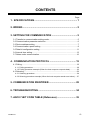
CONTENTS
Page
1. SPECIFICATIONS................................................................1
2. WIRING .................................................................................2
3. SETTING FOR COMMUNICATION ......................................5
3.1 Transfer to communication setting mode.........................................................5
3.2 Communication parameter selection ...............................................................6
3.3 Device address setting ....................................................................................7
3.4 Communication speed setting .........................................................................9
3.5 Data bit configuration setting .........................................................................11
3.6 Interval time setting........................................................................................13
3.7 Notes under communication ..........................................................................16
4. COMMUNICATION PROTOCOL .......................................19
4.1 Polling ............................................................................................................19
4.1.1 Polling procedure..............................................................................................20
4.1.2 Polling procedure example (When the host computer requests data)...............23
4.2 Selecting ........................................................................................................24
4.2.1 Selecting procedure..........................................................................................24
4.2.2 Selecting procedure example (When the host computer sends a set value).....27
5. COMMUNICATION IDENTIFIER.........................................28
6. TROUBLESHOOTING ........................................................34
7. ASCII 7-BIT CODE TABLE (Reference) ............................35
IMCB03-E5
i-3
MEMO
i-4
IMCB03-E5
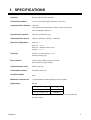
1. SPECIFICATIONS
Interface:
Based on RS-485, EIA standard
Connection method:
2-wire system, half-duplex multi-drop connection
Communication distance: 1 km max.
The maximum communication distance will be affected by
the surrounding conditions.
Synchronous method:
Start/stop synchronous type
Communication speed:
2400 bps, 4800 bps, 9600 bps, 19200 bps
Data bit configuration:
Start bit:
Data bit:
Parity bit:
Stop bit:
Protocol:
ANSI X3.28 subcategory 2.5, A4
Polling/selecting type
Error control :
Vertical parity (With parity bit selected)
Horizontal parity (BCC check)
Communication code:
ASCII 7-bit code
Termination resistor:
Externally connected
Xon/Xoff control:
None
Maximum connections:
32 instruments maximum including a host computer
Signal logic:
RS-485
1
7 or 8
Without, Odd or Even
1 or 2
Signal voltage
Logic
V (A) - V (B) ≥ 2 V
0 (SPACE)
V (A) - V (B) ≤ -2 V
1 (MARK)
Voltage between V (A) and V (B) is the voltage of (A) terminal for
the (B) terminal.
IMCB03-E5
1
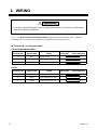
2. WIRING
!
WARNING
In order to prevent electric shock or instrument failure, do not turn on the power
until all the wiring is finished.
Up to 32 CB100/CB400/CB500/CB700/CB900 digital controller (hereinafter, the "controller")
including the host computer can be connected if multidrop connected by RS-485.
Terminal No. and signal details
!"
CB100/CB400/CB500/CB900
Terminal No.
Signal name
Name
13
SG
14
T/R(A)
Send data/Receive data
15
T/R(B)
Send data/Receive data
Terminal No.
Signal name
7
SG
8
T/R(A)
Send data/Receive data
9
T/R(B)
Send data/Receive data
Signal direction
Controller
Host computer
Signal ground
CB700
2
Name
Signal direction
Controller
Host computer
Signal ground
IMCB03-E5
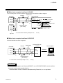
2. WIRING
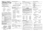
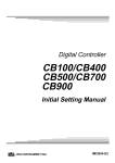
When host computer interface is RS-485
!"
It is necessary that a circuit to transfer send and receive be built-in the host computer.
RS-485
Controller
Paired wire
Host computer
SG
T/R(A)
SG
T/R(A)
T/R(B)
T/R(B)
*R
Controller
RD (RXD):Receive data
Send/receive
selection signal
Twisted pair wire
(with shield)
SG
T/R(A)
SD (TXD):Send data
SD (TXD) and RD (RXD): Negative logic
T/R(B)
#
#
#
Up to 31
*R
*R: Termination resistors (Example: 120 Ω
1/2 W)
When host computer interface is RS-232C
!"
RS-232C/RS-485 converter is required.
RS-485
Controller
RS-232C/RS-485
converter
Paired wire
SG
SG
T/R(A)
T/R(A)
T/R(B)
T/R(B)
*R
Host computer
RS-232C
*R
Twisted pair wire
(with shield)
*R: Termination resistors (Example: 120 Ω
1/2 W)
CAUTION
When the host computer use Windows 95/98/NT, use a RS-232C/RS-485 converter with an
automatic send/receive transfer function.
Recommended: CD485, CD485/V manufactured by Data Link, Inc. or equivalent.
IMCB03-E5
3
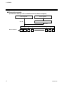
2. WIRING
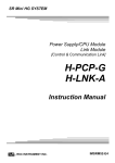
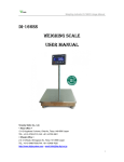
Connection example
!"
(Connection with up to 31 controllers and one host computer)
Host computer
Host computer
RS-232C
RS-232C/RS-485 converter
RS-485
or
RS-485
Junction terminal
Device address
0
1
2
Controller
4
3
28
29
30
Controller
IMCB03-E5
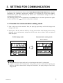
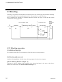
3. SETTING FOR COMMUNICATION
In order to make communication between the CB100/CB400/CB500/CB700/CB900 digital controller
(hereinafter, the "controller") and the host computer, it is necessary to set the device address,
communication speed, data construction and interval time. Communication settings are made in
communication setting mode.
The following pictures used for explanation are for CB900. However, the same operation also applies
to other controllers. The
section in each picture is dimly lit.
3.1 Transfer to communication setting mode
$ Turn on the power to this controller. Thus, the input type, input range and PV/SV display mode
change in this order.
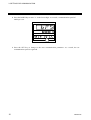
% Pressing the <R/S key while the SET key is being pressed when PV/SV display mode is being
displayed selects communication setting mode. In this mode, device address "Add" are displayed
in the first place.
PV/SV display mode
Communication setting mode
Device address
PV
PV
SV
SV
AT OUT1 OUT2 ALM1 ALM2
AT OUT1 OUT2 ALM1 ALM2
SET
R/S
SET
R/S
NOTES
&"The communication setting mode can be selected anytime when the SV setting mode.
&"In order to terminate the communication setting mode, press the <R/S key while pressing the
SET key. After the communication setting mode terminates, the display changes to the PV/SV
display mode.
IMCB03-E5
5
3. SETTING FOR COMMUNICATION
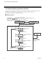
3.2 Communication parameter selection
Parameters in communication setting mode are selected in the order of device address "Add,"
communication speed "bPS," data construction "bIT" and interval time set value "InT."
Each parameter is selected by pressing the SET key.
Display flowchart
!"
Power ON
Input type and input range
display
Display changes automatically
PV/SV display mode
(Display for approx. 4 sec)
Press the
SET key.
SV setting mode
Pressing the <R/S key while the SET key.
Communication setting mode
PV
Device address
(Add)
SV
Press the SET key.
PV
Communication speed
(bPS)
PV/SV display
mode
SV
Press the SET key.
PV
Data bit configuration
(bIT)
Press the <R/S key
while pressing the
SET key.
SV
Press the SET key.
PV
Press the
SET key.
6
Interval time set value
(InT)
SV
IMCB03-E5
3. SETTING FOR COMMUNICATION
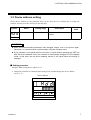
3.3 Device address setting
Set the device address by using numerals from 0 to 99. Press the UP or DOWN key to change the
numeral, and also press the <R/S key to shift the digit.
Symbol
Name
Device address
Setting range
0 to 99
Description
Factory set
value
Sets the controller device
address.
0
Add
CAUTIONS
&"When the communication parameter was changed, always turn on the power again.
Otherwise, no communication is performed by using the changed value.
&"If key operation is not performed for more than 1 minute without pressing the SET key
after the device address is set, the controller is automatically changed to PV/SV display
mode. In this case, the set device address returns to the value before the setting is
changed.
Setting procedure
!"
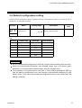
Example: When setting device address to 15.
1. Change the controller to communication setting mode, and then display the device address
(See P. 5, 6).
Device address
PV
SV
AT OUT1 OUT2 ALM1 ALM2
SET
IMCB03-E5
R/S
7
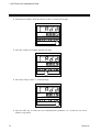
3. SETTING FOR COMMUNICATION
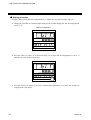
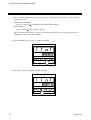
2. Set the device address. Press the UP key to enter "5" in the lowest digit.
PV
SV
AT OUT1 OUT2 ALM1 ALM2
SET
R/S
3. Press the <R/S key to brightly light the tens digit.
PV
SV
AT OUT1 OUT2 ALM1 ALM2
SET
R/S
4. Press the UP key to enter "1" in the tens digit.
PV
SV
AT OUT1 OUT2 ALM1 ALM2
SET
R/S
5. Press the SET key to select the next communication parameter. As a result, the set device
address is registered.
8
IMCB03-E5
3. SETTING FOR COMMUNICATION
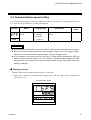
3.4 Communication speed setting
Set a communication speed of 2400 bps, 4800 bps, 9600 bps or 19200 bps by using numerals from 0
to 3. Press the UP or DOWN key to change the numeral.
Symbol
Name
Communication
speed
bPS
Setting range
0 : 2400 bps
1 : 4800 bps
2 : 9600 bps
3 : 19200 bps
Description
Selects the communication
speed.
Factory set
value
2
CAUTIONS
&"Set the same communication speed to both the controller and connecting host computer.
&"When the communication parameter was changed, always turn on the power again.
Otherwise, no communication is performed by using the changed value.
&"If key operation is not performed for more than 1 minute without pressing the SET key
after the communication speed is set, the controller is automatically changed to PV/SV
display mode. In this case, the set communication speed returns to the value before the
setting is changed.
Setting procedure
!"
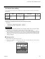
Example: When setting communication speed to "1: 4800 bps."
1. Change the controller to communication setting mode, and then display the communication
speed (See P. 5, 6).
Communication speed
PV
SV
AT OUT1 OUT2 ALM1 ALM2
SET
IMCB03-E5
R/S
9
3. SETTING FOR COMMUNICATION
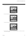
2. Press the DOWN key to enter "1" in the lowest digit. As a result, a communication speed of
4800 bps is set.
PV
SV
AT OUT1 OUT2 ALM1 ALM2
SET
R/S
3. Press the SET key to change to the next communication parameter. As a result, the set
communication speed is registered.
10
IMCB03-E5
3. SETTING FOR COMMUNICATION
3.5 Data bit configuration setting
Set the data bit configuration during communication by using numerals from 0 to 5. Press the UP or
DOWN key to change the numeral.
Symbol
Name
Data bit
configuration
Setting range
0 to 5
See *A
Description
Selects data bit configuration
during communication.
Factory set
value
0
bIT
*A
Setting
Data bit [bit]
Parity bit
Stop bit [bit]
0
8
None
1
1
8
None
2
2
7
Even
1
3
7
Even
2
4
7
Odd
1
5
7
Odd
2
CAUTIONS
&"Set the same data bit configuration to both the controller and connecting host computer.
&"When the communication parameter was changed, always turn on the power again.
Otherwise, no communication is performed by using the changed value.
&"If key operation is not performed for more than 1 minute without pressing the SET key
after the data bit configuration is set, the controller is automatically changed to PV/SV
display mode. In this case, the set data bit configuration returns to the value before the
setting is changed.
IMCB03-E5
11
3. SETTING FOR COMMUNICATION
Setting procedure
!"
Example: When setting data bit configuration to "1: 8 data bits, no parity bit and 2 stop bits."
1. Change the controller to communication setting mode, and then display the data bit configuration
(See P. 5, 6).
Data bit configuration
PV
SV
AT OUT1 OUT2 ALM1 ALM2
SET
R/S
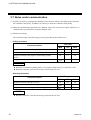
2. Press the UP key to enter "1" in the lowest digit. As a result, data bit configuration is set to "8
data bits, no parity bit and 2 stop bits."
PV
SV
AT OUT1 OUT2 ALM1 ALM2
SET
R/S
3. Press the SET key to change to the next communication parameter. As a result, the set data bit
configuration is registered.
12
IMCB03-E5
3. SETTING FOR COMMUNICATION
3.6 Interval time setting
Set the interval time. Press the UP or DOWN key to change the numeral, and press the <R/S key to
shift the digit.
Symbol
Name
Interval time set
value
Setting range
0 to 150
*A
Description
Sets the value to set the
interval time.
Factory set
value
5
InT
*A : Can be set up to 250 ms if converted to interval time.
Equations for calculating interval time and interval time set value
Equations :
Interval time = Interval time set value × 1.666 ms
Interval time set value = Interval time ÷ 1.666 ms
CAUTIONS
&"When the communication parameter was changed, always turn on the power again.
Otherwise, no communication is performed by using the changed value.
&"If key operation is not performed for more than 1 minute without pressing the SET key
after the interval time set value is set, the controller is automatically changed to PV/SV
display mode. In this case, the set interval time set value returns to the value before the
setting is changed.
Setting procedure
!"
Example: When setting interval time to 250 ms.
1. Change the controller to communication setting mode, and then display the interval time set
value (See P. 5, 6).
Interval time set value
PV
SV
AT OUT1 OUT2 ALM1 ALM2
SET
IMCB03-E5
R/S
13
3. SETTING FOR COMMUNICATION
2. Here, as an interval time of 250 ms needs to be set, calculate the interval time set value using the
equation (See P. 13).
Interval time set value:
250 ms ÷ 1.666 ms 150 (Round to the nearest whole number.)
Interval time:
150 × 1.666 ms 249.9 (Approx. 250 ms)
Thus, enter an interval time set value of 150 calculated from the above by pressing the UP or
DOWN key at the front of the controller.
3. Press the DOWN key to enter "0" in the lowest digit.
PV
SV
AT OUT1 OUT2 ALM1 ALM2
SET
R/S
4. Press the <R/S key to brightly light the tens digit.
PV
SV
AT OUT1 OUT2 ALM1 ALM2
SET
14
R/S
IMCB03-E5
3. SETTING FOR COMMUNICATION
5. Press the UP key to enter "5" in the tens digit.
PV
SV
AT OUT1 OUT2 ALM1 ALM2
SET
R/S
6. Press the <R/S key to brightly light the hundreds digit.
PV
SV
AT OUT1 OUT2 ALM1 ALM2
SET
R/S
7. Press the UP key to enter "1" in the hundreds digit.
PV
SV
AT OUT1 OUT2 ALM1 ALM2
SET
R/S
8. Press the SET key to change to the next communication parameter. As a result, the set interval
time set value is registered.
IMCB03-E5
15
3. SETTING FOR COMMUNICATION
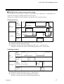
3.7 Notes under communication
(1) If polling is made by specifying the identifier of the function which is not added to the controller,
the controller sends [EOT]. In addition, if selecting is made, the controller sends [NAK].
(2) When the communication parameter was changed, always turn on the power again. Otherwise, no
communication is performed by using the changed value.
(3) Send/receive timing
The controller requires the following processing times during data send/receive.
Polling procedure
Procedure details
Time (ms)
MIN
TYP
MAX
Response send time after calling [ENQ] receive
1.5
2.0
3.0
Response send time after acknowledgment [ACK] receive
1.5
2.0
3.5
Response send time after negative acknowledge [NAK]
receive
1.0
1.5
3.0
0.7
1.0
Response send time after BCC send
NOTES
&"Data-link is terminated sending [EOT], if no response within about 3 sec after BCC send.
&"Response send time is the time at having set interval time in 0 ms.
Selecting procedure
Procedure details
Time (ms)
MIN
TYP
MAX
2.0
3.0
4.0
Response wait time after acknowledgment [ACK] send
0.7
1.0
Response wait time after negative acknowledge [NAK] send
0.7
1.0
Response send time after BCC receive
NOTE
&"Response send time is the time at having set interval time in 0 ms.
16
IMCB03-E5
3. SETTING FOR COMMUNICATION
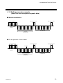
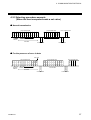
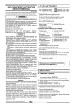
RS-485 (2-wire system) send/receive timing
!"
The transmission and reception of RS-485 communication are operated by a transmitting wire.
Therefore, the timing of switching should be acted correctly.
Send/receive example in the host computer and controller is show in the following.
Polling procedure
Send
data
Possible
(Possible/
H ost
com puter
Im possible
Im possible)
Sending
status
C ontroller
E
O
T
……
Send
data
Possible
(Possible/
Im possible)
Im possible
N
A
C or A
K
K
E
N
Q
(a)
Sending
status
(b)
S
T
X
……
(c)
B
C
C
(a): (Response send time after calling [ENQ] receive) + (Interval time)
(b): Response send time after [BCC] send
(c): (Response send time after acknowledgment [ACK] receive + (Interval time) or
(Response send time after negative acknowledge [NAK] receive + (Interval time)
Selecting procedure
S end
data
H ost
com puter
P ossible
(Possible/
Im possible)
Im possible
S ending
status
S end
data
(Possible/
C ontroller
Im possible)
S
T
X
………
B
C
C
P ossible
(a)
Im possible
S ending
status
(b)
A
N
C or A
K
K
(a): (Response send time after BCC receive) + (Interval time)
(b): Response wait time after acknowledgment [ACK] send or
Response wait time after negative acknowledge [NAK] send
IMCB03-E5
17
3. SETTING FOR COMMUNICATION
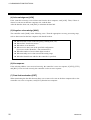
When host computer is selected from data sending to data receiving
!"
When switching the host computer into reception from transmission, it must be confirmed that the
data was surely put on line. This is not observe the transmission buffer of host computer itself, but
confirming with shift register.
Transmission
data
8 bit
Transmission
buffer
8 bit
Shift register
Transmission
data
Transmitting 1 bit each
Next, the controller side secures the maximum time until the transmission line changes to the data
receiving side (until the controller is ready to send data) after the host computer has received the stop
bit corresponding to the final character. This maximum time corresponds to interval time.
If no interval time is set, the controller side may be set to the send state even when the host computer
side is not set to the receive state. As a result, no communication is conducted correctly. In addition,
set the interval time so as to match the host computer.
When host computer is selected from data receiving to data sending
!"
Polling procedure "Response wait time after BCC send" or selecting procedure "Response wait time
after [ACK] or [NAK] send" is processing time required during controller data sending. Therefore,
select the host computer from receiving to sending after the lapse of the above time.
As for the necessary processing time, refer to the table of page 16.
(4) A transmission error may occur with the transmission line disconnected, shorted or set to the highimpedance state. In order to prevent the above error, it is recommended that the fail-safe function
be provided on the receiver side of the host computer. The fail-safe function can prevent a framing
error from its occurrence by making the receiver output stable to the MARK (1) when the
transmission line is in the high-impedance state.
(5) The nonvolatile memory (EEPROM) for data backup has limitations on the number of memory
rewrite times (approx. 100,000 times). Avoid using the memory to frequently change the set value
via communication.
18
IMCB03-E5
4. COMMUNICATION PROTOCOL
The CB100/CB400/CB500/CB700/CB900 digital controller (hereinafter, the "controller") uses the
polling/selecting method to establish a data link. The basic procedure is followed ANSI X3.28
subcategory 2.5, A4 basic mode data transmission control procedure (Fast selecting is established for
selecting).
!"In the polling/selecting method, the controller is controlled completely by the host computer is
permitted. Since the host computer invites information message sending from and receiving to the
controller, send the data in accordance with the polling or selecting procedure. (Centralized control
method)
!"The code use in communication is 7-bit ASCII code including transmission control character. The
transmission control characters are [EOT] (04H), [ENQ] (05H), [ACK] (06H), [NAK] (15H),
[STX] (02H) and [ETX] (03H). The figure in the parenthesis is indicating hexadecimal number.
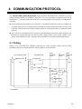
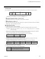
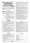
4.1 Polling
Polling is an action that host computer requesting one of the controller which selected among
multidrop connected, to transmit the data. The procedure is as the following.
Host computer send
E
O
T
E
[Address] [ ID ] N
Q
(1)
(2)
Controller send
Host
computer
send
Controller
send
No response
(5)
E
O
T (4)
E
S
T [ ID ] [ Data ] T [ BCC ]
X
X
(3)
Host
computer
send
E
O
T
(10)
No (8)
response
(9)
Time
out
E
O
T
Indefinite
A (6)
C
K
N
A
(7) K
ID: Identifier
IMCB03-E5
19
4. COMMUNICATION PROTOCOL
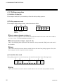
4.1.1 Polling procedure
(1) Initialize of data link
Host computer sends [EOT] for initializing of data link before polling sequence.
(2) Polling sequence send
Host computer sends polling sequence with a format shown below.
#
$
Example:
%
ENQ
0
2
M
1
ENQ
Device Identifier
address
# Device address [Number of digits: 2]
This data is a device address of the controller for polled and must be the same as the device address
set value in item "3.3 Device address setting" (P. 7).
$ Identifier [Number of digits : 2] (See P. 28.)
This is for identifying data requested for the controller. Always attach the [ENQ] code to the end of
the identifier.
% [ENQ]
This is the transmission control character which indicates the end of the polling sequence. Then, the
host computer waits for response from the controller.
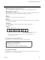
(3) Controller data send
If the polling sequence is received correctly, the controller sends data in the following format.
#
$
%
'
&
STX
Identifier
Data
ETX
BCC
# [STX]
This is the transmission control character which indicates the start of the text (identifier and data).
20
IMCB03-E5
4. COMMUNICATION PROTOCOL
$ Identifier [Number of digits: 2] (See P. 28.)
This is for identifying data (measured value, status and set value) sent to the host computer.
% Data [Number of digits: 6]
Data indicated by the identifier belonging to the controller. It is expressed in decimal ASCII code
including a minus sing (-) and a decimal point. No zero suppression is made.
' [ETX]
A transmission control character used to indicate text end.
& [BCC]
BCC (Block Check Character) for error detection using horizontal parity. BCC is calculated by
horizontal parity (even number).
<Algorithm>
Take off EX-OR (exclusive OR) of all character from next [STX] through [ETX].
Not including [STX].
Example:
In the case of the data are :
STX
M
1
0
0
0
5
0
0
4DH 31H 30H 30H 30H 35H 30H 30H
ETX
BCC
In the parenthesis are indicated with
hexadecimal number.
BCC = 4DH ⊕ 31H ⊕ 30H ⊕ 30H ⊕ 30H ⊕ 35H ⊕ 30H ⊕ 30H ⊕ 03H = 7AH
Value of BCC becomes 7AH.
(4) Controller data send end (EOT send)
If the following cases, the controller sends [EOT] to terminate the data link.
"
!"When there is no specified identifier.
!"When there is an error in the data type.
!"When all the data has been sent.
!"When a identifier not added to the controller is specified.
"
(5) Controller no response
The controller is set to no response when the polling sequence is not received correctly. If necessary,
take time out recovery etc. for the host computer.
IMCB03-E5
21
4. COMMUNICATION PROTOCOL
(6) Acknowledgment [ACK]
Send [ACK] when the host computer could receive data items correctly.
Next, the controller sends the identifier data following the identifier just sent in succession shown in
"(Communication identifier list" (P. 28).
If data send from the controller is suspend, send [EOT] to terminate the data link.
(7) Negative acknowledge [NAK]
If the host computer cannot receive send data correctly from the controller, it sends [NAK] to the
controller. Then, the controller re-sends the same data to the host computer.
As the number of re-send times is not specified, take the necessary measures on the host computer
side if no recovery is made.
(8) No response from host computer
When the host computer is set to no response after the controller sends data, the controller sends
[EOT] as time-out processing to terminate the data link (time-out time : about 3 sec).
(9) Indefinite response from host computer
When the response from the host computer is indefinite, the controller sends [EOT] to terminate the
data link.
(10) Data link termination [EOT]
If it is necessary to suspend communication with the controller or to terminate the data link due to no
response from the controller, the host computer sends [EOT].
22
IMCB03-E5
4. COMMUNICATION PROTOCOL
4.1.2 Polling procedure example
(When the host computer requests data)
Normal transmission
("
Host computer send
E
O 0
T
1
M
1
Host computer send
E
N
Q
04H 30H 31H 4DH 31H 05H
S
T
X
Polling Identifier
address
M
1
0
0
1
0
.
0
E
T
X
Host computer send
A
C
K
E
O
T
06H
04H
S
T
X
B
C
C
02H 4DH 31H 30H 30H 31H 30H 2EH 30H 03H 60H
A
A
0
0
0
0
0
E
T
X
B
C
C
02H 41H 41H 30H 30H 30H 30H 30H 30H 03H 03H
Next send data
Controller send
Data
Identifier
0
Send data
Controller send
For the presence of error in data
("
Host computer send
E
O 0
T
1
M
1
Host computer send
E
N
Q
Error data
04H 30H 31H 4DH 31H 05H
Polling Identifier
address
S
T
X
M
1
0
0
1
02H 4DH 31H 30H 30H 31H
Identifier
.
E
T
X
B
C
C
2EH 30H 03H 60H
Data
Send data
Controller send
IMCB03-E5
0
Host computer send
N
A
K
A
C
K
15H
06H
S
T
X
M
1
0
0
1
0
.
0
E
T
X
B
C
C
02H 4DH 31H 30H 30H 31H 30H 2EH 30H 03H 60H
Re-send data
Controller send
23
4. COMMUNICATION PROTOCOL
4.2 Selecting
Selecting is an operation in which the host computer selects one from among the controllers multidrop
connected and then of recommending data receive. The procedure is as the following.
Due to adopted fast selecting in controllers therefore becomes the type to send the data which
connected to selecting sequence.
Host computer send
E
O
T
(1)
[Address]
E
S
T [ Identifier ] [ Data ] T [ BCC ]
X
X
(2)
(3)
Controller send
No response
(6)
A
C
K (4)
N
A
K
Host
computer
send
E
O
T
(7)
(5)
4.2.1 Selecting procedure
(1) Initialize of data link
Host computer sends [EOT] for initializing of data link before selecting sequence.
(2) Selecting address send
Send the selecting address selected as the selecting sequence from the host computer.
[Device address] (Number of digits : 2)
This data is a device address of the controller to be selected and must be the same as the device
address set value in item "3.3 Device address setting" (P. 7).
24
IMCB03-E5
4. COMMUNICATION PROTOCOL
(3) Data send
Host computer to send the data with a format indicated below continuing the selecting sequence.
STX
#
$
Identifier
Data
ETX
BCC
* For [STX], [ETX] and [BCC], see item "4.1 Polling" (P. 19).
# Identifier [Number of digits : 2] (See P. 28.)
This identifies the data (set value) which is sent by the host computer.
$ Data [Number of digits : 6]
Data is the information being sent to the controller. It is expressed in decimal ASCII code including
a minus sign (-) and a decimal point (period).
!"About numerical data
The data that receipt of letter is possible
• Data with numbers below the decimal point omitted or zero suppressed data can be received.
<Example> When data send with -001.5, -01.5, -1.5, -1.50, -1.500 at the time of -1.5, controller
can receive a data.
• When the host computer send data with decimal point to item of without decimal point, controller
receives a message with the value which cut off below the decimal point.
<Example> When setting range is 0 to 200, controller receives as a following.
Send data
Receive data
0.5
100.5
0
100
• Controller receives value in accordance with decided place after the decimal point. The value
below the decided place after the decimal point is cut off.
<Example> When setting range is -10.00 to +10.00, controller receives as a following.
Send data
Receive data
-.5
-.058
.05
-0
-0.50
-0.05
0.05
0.00
The data that receipt of letter is impossible
Controller sends NAK when received a following data.
IMCB03-E5
+
Plus sign and the data that gained plus sing
-
Only minus sign (there is no figure)
.
Only decimal point (period)
25
4. COMMUNICATION PROTOCOL
(4) Acknowledgment [ACK]
If the controller correctly received data sent from the host computer, send [ACK]. Then, if there is
data to be sent next on the host computer side, send the data.
After the data has been sent, send [EOT] to terminate the data link.
(5) Negative acknowledge [NAK]
The controller sends [NAK] in the following cases. Then the appropriate recovery processing steps,
such as data resend on the host computer side should be taken.
!"When an error occurs on the line (parity, framing error, etc.).
!"When a BCC check error occurs.
!"When there is no identifier.
!"When receive data is not in the specified configuration
(Text is not in the "Identifier + data construction.")
!"When the number of receive data digits exceeds 6.
!"When normally receive data exceeds the setting range.
!"When the identifier not added to the controller is specified.
(6) No response
If the selecting address is not received correctly, the controller is set to no response, if [STX], [ETX]
and [BCC] is not received correctly, the controller is also set to no response.
(7) Data link termination [EOT]
When terminating the data link because there was no more to be sent on the host computer side or the
controller was set to no response, send [EOT] from the host computer.
26
IMCB03-E5
4. COMMUNICATION PROTOCOL
4.2.2 Selecting procedure example
(When the host computer sends a set value)
Normal transmission
("
Host computer send
E
O
T
0
1
S
T
X
S
1
2
0
0
Host computer send
.
0
E
T
X
S
T
X
B
C
C
04H 30H 31H 02H 53H 31H 32H 30H 30H 2EH 30H 03H 4DH
Selecting
address
1
1
.
0
B
C
C
E
O
T
02H 50H 31H 31H 2EH 30H 03H 4DH
A
C
K
Data
Identifier
P
Host computer send
E
T
X
04H
A
C
K
Next send data
06H
06H
Controller send
Controller send
Send data
For the presence of error in data
("
Error data
Host computer send
E
O
T
0
1
S
T
X
S
1
2
1
0
Host computer send
.
0
E
T
X
B
C
C
S
T
X
04H 30H 31H 02H 53H 31H 32H 31H 30H 2EH 30H 03H 4DH
Selecting
address
Identifier
Data
Send data
1
2
0
0
.
0
B
C
C
S
T
X
02H 53H 31H 32H 30H 30H 2EH 30H 03H 4DH
N
A
K
15H
Controller send
IMCB03-E5
S
Host computer send
E
T
X
Re-send data
P
1
……
02H 50H 31H
A
C
K
06H
Controller send
27
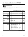
5. COMMUNICATION IDENTIFIER
Communication identifier list
("
NOTES
!"Communication is not possible when an identifier is specified that the controller can not
recognize.
!"The number of digits is 6 for all data.
(Attributes
Identifier
Name
RO: Read only, R/W: Read/Write)
Data range
Factory set
value
Attribute
Measured value (PV)
M1
Within input range
----
RO
Current transformer input 1
M2
0.0 to 100.0 A
----
RO
M3
0.0 to 100.0 A
----
RO
AA
0: OFF
1: ON
----
RO
AB
0: OFF
1: ON
----
RO
Burnout
B1
0: OFF
1: ON
----
RO
Error code
ER
0 to 255
----
RO
RUN/STOP transfer
SR
0: RUN
0
R/W
Set value (SV)
S1
Within input range
0
R/W
Alarm 1 setting
A1
Temperature input
Process alarm, deviation alarm,
SV alarm:
-1999 to +9999 °C [°F] or
-199.9 to +999.9 °C [°F]
Voltage/ current inputs
Deviation alarm: -span to +span
(Within 9999)
Temperature
input:
50 or 50.0
R/W
See *1.
Current transformer input 2
See *2.
Alarm 1 status
See *3.
Alarm 2 status
See *1.
See *3.
Alarm 2 setting
A2
See *1.
See *4.
1: STOP
Voltage/
current
inputs: 5.0
Process alarm, SV alarm:
Within input range
Continued on the next page.
28
IMCB03-E5
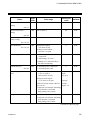
5. COMMUNICATION IDENTIFIER
Identifier
Name
Heater break alarm 1
setting
Data range
Factory set
value
Attribute
A3
0.0 to 100.0 A
0.0
R/W
A4
0.0 to 100.0 A
0.0
R/W
A5
0.1 to 200.0 min.
8.0
R/W
A6
Temperature input:
0 to 9999 °C [°F]
0
R/W
0
R/W
0
R/W
Temperature
input:
30 (30.0)
R/W
See *1.
Heater break alarm 2
setting
See *2.
Control loop break alarm
(LBA) setting
See *1, *3.
LBA deadband
See *1, *3.
Voltage/current inputs:
0 to 100 % of span
Autotuning (AT)
G1
0: Autotuning (AT) end or
suspension
1: Autotuning (AT) start
*Change to "0" automatically at
the end of Autotuning.
Self-tuning (ST)
G2
0: Self-tuning (ST) suspension
1: Self-tuning (ST) start
P1
Temperature input:
1 (0.1) to span or
9999 (999.9) °C [°F]
See *5.
Heat-side proportional
band
Voltage/current inputs :
0.1 to 100.0 % of span
Voltage/
current
inputs: 3.0
(ON/OFF action control when set
to 0 or 0.0.)
*Cannot be set while the self-tuning
(ST) function is activated.
Only polling can be made.
Integral time
I1
1 to 3600 sec (0: PD control)
240
R/W
*Cannot be set while the self-tuning
(ST) function is activated.
Only polling can be made.
Continued on the next page.
IMCB03-E5
29
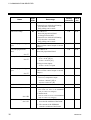
5. COMMUNICATION IDENTIFIER
Identifier
Name
Data range
Factory
set value
Attribute
Derivative time
D1
1 to 3600 sec (0: PI control)
*Cannot be set while the self-tuning
(ST) function is activated.
Only polling can be made.
60
R/W
Anti-reset windup
W1
100
R/W
Heat-side proportioning
cycle
T0
1 to 100 % of
heat-side proportional band
(0: Integral action OFF)
*Cannot be set while the self-tuning
(ST) function is activated.
Only polling can be made.
1 to 100 sec
(Not set if the control output is current
output.)
See *6.
R/W
Cool-side proportional
band
P2
1 to 1000 % of
heat-side proportional band
100
R/W
V1
Temperature input:
-10 to +10 °C [°F] or
-10.0 to +10.0 °C [°F]
0 or 0.0
R/W
See *7.
Overlap/deadband
See *7.
Voltage/current inputs:
-10.0 to +10.0 % of span
Cool-side proportioning
cycle
T1
1 to 100 sec
(Not set if the control output is current
output.)
See *8.
R/W
PV bias
PB
-span to +span
However, temperature input:
-1999 to +9999 °C [°F] or
-199.9 to +999.9 °C [°F]
0 or 0.0
R/W
Set data lock function
LK
0 to 7
0
R/W
EEPROM storage mode
EB
0: Backup mode
0
R/W
-----
RO
See *7.
See *9.
(Set values are store to the EEPROM
when set values are changed.)
1: Buffer mode
(Not set values are store to the EEPROM
when set values are changed.)
See *10.
EEPROM storage state
See *11.
EM
0: The content of the EEPROM does
not coincide with that of the RAM.
1: The content of the EEPROM
coincides with that of the RAM.
30
IMCB03-E5
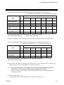
5. COMMUNICATION IDENTIFIER
*1: The communicable identifier differs depending on the alarm type specified in alarm 2.
− : Communication is impossible
× : Communication is possible
The alarm type specified in alarm 2
Name
Current transformer
input 1
Alarm 2 status
Alarm 2 setting
Heater break alarm 1
setting
Control loop break
alarm setting
LBA deadband
Identifier
Deviation
alarm
Process
alarm
LBA
*
HBA
**
SV alarm
No
alarm
M2
−
−
−
×
−
−
AB
A2
A3
×
×
−
×
×
−
×
−
−
×
−
×
×
×
−
−
−
−
A5
−
−
×
−
−
−
A6
−
−
×
−
−
−
As control loop break alarm, only either the alarm 1 or alarm 2 is specified.
*LBA: Control loop break alarm
**HBA: Heater break alarm
*2: This is an identifier which enables communication when specifying to the Z-168 specification.
*3: The communicable identifier differs depending on the alarm type specified in alarm 1.
− : Communication is impossible
× : Communication is possible
The alarm type specified in alarm 1
Name
Alarm 1 status
Alarm 1 setting
Control loop break
alarm setting
LBA deadband
Identifier
Deviation
alarm
Process
alarm
LBA
*
SV alarm
No
alarm
AA
A1
A5
×
×
−
×
×
−
×
−
×
×
×
−
−
−
−
A6
−
−
×
−
−
As control loop break alarm, only either the alarm 1 or alarm 2 is specified.
*LBA: Control loop break alarm
*4: Any number other than "0" indicates errors (RAM write error, etc.) detected by the controller selfdiagnosis function. Please contact RKC sales office or the agent.
*5: • In a controlled system in which ripples may be contained by the application of periodic
disturbances, use this instrument with the self-tuning function turned off.
• This is an identifier which enables communication at PID action with autotuning (Reverse
action/Direct action).
*6: Relay contact output: 20 sec
Voltage pulse output, Trigger output for triac driving, Triac output: 2 sec
IMCB03-E5
31
5. COMMUNICATION IDENTIFIER
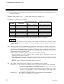
*7: This is an identifier which enables communication at heat/cool PID action with autotuning (Water
cooling/Air cooling).
*8: Relay contact output: 20 sec
Voltage pulse output, Triac output: 2 sec
*9: Details of set data lock level selection.
− : Unsettable (Data locked)
×: Settable (Data unlocked)
Alarm setting
*A
(Alarm 1, Alarm 2)
Other setting items
0
×
×
×
1
×
×
−
2
×
−
×
3
×
−
−
4
−
×
×
5
−
×
−
6
−
−
×
7
−
−
−
*A: All setting items other than set value and alarm settings (alarm 1 or alarm 2).
Set data
Set value
NOTE
The set data lock function is effective only for the setting performed by key operation. Setting
items in the data lock state cannot be set by key operation, but can a always be selected via
communication.
*10: The non-volatile memory (EEPROM) has limitations on the number of memory rewrite times.
If the buffer mode is selected as an EEPROM storage mode, all of the set values changed are
not written to the EEPROM and thus a problem of limitations on the number of memory rewrite
times can be solved. When the memory is used to frequently change the set value via
communication, select the buffer mode.
When selecting any EEPROM storage mode, take notice of the following.
• If power failure occurs while the buffer mode is selected, the set value returns to the value
before the storage mode is selected.
• If the buffer mode is changed to the backup mode, all of the set values at that time are stored
to the EEPROM. If necessary to backup the final value of each set item, select the backup
mode.
• When the power is turned on, the backup mode is always set.
*11: The contents of the buffer memory and those of the EEPROM can be checked.
When data is 0: The contents of the buffer memory do not match with those of the EEPROM.
• As data is being written to the EEPROM in backup mode, do not turn the
power off. If turned off, no set values are stored.
• If the set value is changed after the backup mode is changed to the buffer
mode, 0 is set (mismatch). As the set value changed is not backup, select
the backup mode if necessary.
When data is 1: The contents of the buffer memory match with those of the EEPROM.
(Data write to the EEPROM is completed.)
32
IMCB03-E5
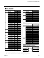
5. COMMUNICATION IDENTIFIER
!"
Input range table
Thermocouple input
Code
Input type
K
J
R
S
B
E
N
T
W5Re/
W26Re
0 to 200 °C
0 to 400 °C
0 to 600 °C
0 to 800 °C
0 to 1000 °C
0 to 1200 °C
0 to 1372 °C
0 to 100 °C
0 to 300 °C
0 to 450 °C
0 to 500 °C
0 to 800 °F
0 to 1600 °F
0 to 2502 °F
20 to 70 °F
0 to 200 °C
0 to 400 °C
0 to 600 °C
0 to 800 °C
0 to 1000 °C
0 to 1200 °C
0 to 450 °C
0 to 800 °F
0 to 1600 °F
0 to 2192 °F
0 to 400 °F
0 to 300 °F
0 to 1600 °C *1
0 to 1769 °C *1
0 to 1350 °C *1
0 to 3200 °F *1
0 to 3216 °F *1
0 to 1600 °C *1
0 to 1769 °C *1
0 to 3200 °F *1
0 to 3216 °F *1
400 to 1800 °C
0 to 1820 °C *1
800 to 3200 °F
0 to 3308 °F *1
0 to 800 °C
0 to 1000 °C
0 to 1600 °F
0 to 1832 °F
0 to 1200 °C
0 to 1300 °C
0 to 2300 °F
0 to 2372 °F
-199.9 to +400.0 °C *2
-199.9 to +100.0 °C *2
-100.0 to +200.0 °C
0.0 to 350.0 °C
-199.9 to +752.0 °F *2
-100.0 to +200.0 °F *2
-100.0 to +400.0 °F *2
0.0 to 450.0 °F
0.0 to 752.0 °F
0 to 2000 °C
0 to 2320 °C
0 to 4000 °F
Code
Input
Range
K
K
K
K
K
K
K
K
K
K
K
K
K
K
K
J
J
J
J
J
J
J
J
J
J
J
J
R
R
R
R
R
S
S
S
S
B
B
B
B
E
E
E
E
N
N
N
N
T
T
T
T
T
T
T
T
T
W
W
W
01
02
03
04
05
06
07
13
14
17
20
A1
A2
A3
A9
01
02
03
04
05
06
10
A1
A2
A3
A6
A7
01
02
04
A1
A2
01
02
A1
A2
01
02
A1
A2
01
02
A1
A2
01
02
A1
A2
01
02
03
04
A1
A2
A3
A4
A5
01
02
A1
Input type
PL II
U
L
0 to 1300 °C
0 to 1390 °C
0 to 1200 °C
0 to 2400 °F
0 to 2534 °F
-199.9 to +600.0 °C *2
-199.9 to +100.0 °C *2
0.0 to 400.0 °C
-199.9 to +999.9 °F *2
-100.0 to +200.0 °F *2
0.0 to 999.9 °F
0 to 400 °C
0 to 800 °C
0 to 800 °F
0 to 1600 °F
Input
Range
A
A
A
A
A
U
U
U
U
U
U
L
L
L
L
01
02
03
A1
A2
01
02
03
A1
A2
A3
01
02
A1
A2
RTD input
Code
Input type
Pt100
JPt100
-199.9 to +649.0 °C
-199.9 to +200.0 °C
-100.0 to +50.0 °C
-100.0 to +100.0 °C
-100.0 to +200.0 °C
0.0 to 50.0 °C
0.0 to 100.0 °C
0.0 to 200.0 °C
0.0 to 300.0 °C
0.0 to 500.0 °C
-199.9 to +999.9 °F
-199.9 to +400.0 °F
-199.9 to +200.0 °F
-100.0 to +100.0 °F
-100.0 to +300.0 °F
0.0 to 100.0 °F
0.0 to 200.0 °F
0.0 to 400.0 °F
0.0 to 500.0 °F
-199.9 to +649.0 °C
-199.9 to +200.0 °C
-100.0 to +50.0 °C
-100.0 to +100.0 °C
-100.0 to +200.0 °C
0.0 to 50.0 °C
0.0 to 100.0 °C
0.0 to 200.0 °C
0.0 to 300.0 °C
0.0 to 500.0 °C
Input
Range
D
D
D
D
D
D
D
D
D
D
D
D
D
D
D
D
D
D
D
P
P
P
P
P
P
P
P
P
P
01
02
03
04
05
06
07
08
09
10
A1
A2
A3
A4
A5
A6
A7
A8
A9
01
02
03
04
05
06
07
08
09
10
Voltage input and Current input
Code
Input type
0 to 5 V DC
0 to 10 V DC *
1 to 5 V DC
0.0
100.0 %
0 to 20 mA DC
4 to 20 mA DC
* Z-1010 specification
to
Input
Range
4
5
6
01
01
01
7
8
01
01
*1: 0 to 399 °C/0 to 751 °F: Accuracy is not guaranteed.
*2: -199.9 to -100.0 °C/-199.9 to -148.0 °F : Accuracy is not guaranteed.
IMCB03-E5
33
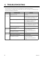
6. TROUBLESHOOTING
This section lists some of the main causes and solutions for communication problems.
If you can not solve a problem, please contact RKC sales office or the agent, on confirming the type
name and specifications of the product.
Problem
No response
Probable cause
Trouble with and imperfect contact of
communication cable
Check communication cables and
connectors.
Incorrect communication speed
Set the communication speed suitable for
the host computer by referring to "3.4
Communication speed setting" (P. 9).
Device address designation differs
Make reassignment after checking the
device address by referring to "3.3
Device address setting" (P. 7).
Incorrect data bit configuration
Make reassignment after checking the
data bit configuration by referring to "3.5
Data bit configuration setting" (P. 11).
Transmission line is not set to the
receive state after data send
Check a program on the host computer
side.
Incorrect identifier
The identifier of a function not added to
the controller is specified
Make re-setting after checking the
identifier by referring to
"!Communication identifier list"
(P. 28).
BCC error
Check BCC of the transmission data.
Data exceeds the setting range
Check a data range.
The identifier of a function not added to
the controller is specified
Make re-setting after checking the
identifier by referring to
"!Communication identifier list"
(P. 28).
EOT return
NAK return
34
Solution
IMCB03-E5
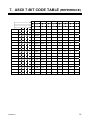
7. ASCII 7-BIT CODE TABLE (REFERENCE)
b5 to b7
IMCB03-E5
b7
0
0
0
0
1
1
1
1
b6
0
0
1
1
0
0
1
1
b5
0
1
0
1
0
1
0
1
0
1
2
3
4
5
6
7
b4 b3 b2 b1
0
0
0
0
0
NUL
DLE
SP
0
@
P
‘
p
0
0
0
1
1
SOH
DC1
!
1
A
Q
a
q
0
0
1
0
2
STX
DC2
”
2
B
R
b
r
0
0
1
1
3
ETX
DC3
#
3
C
S
c
s
0
1
0
0
4
EOT
DC4
$
4
D
T
d
t
0
1
0
1
5
ENQ
NAK
%
5
E
U
e
u
0
1
1
0
6
ACK
SYM
&
6
F
V
f
v
0
1
1
1
7
BEL
ETB
’
7
G
W
g
w
1
0
0
0
8
BS
CAN
(
8
H
X
h
x
1
0
0
1
9
HT
EM
)
9
I
Y
i
y
1
0
1
0
A
LF
SUB
*
:
J
Z
j
z
1
0
1
1
B
VT
ESC
+
;
K
[
k
{
1
1
0
0
C
FF
FS
,
<
L
¥
l
|
1
1
0
1
D
CR
GS
-
=
M
]
m
}
1
1
1
0
E
SO
RS
.
>
N
^
n
˜
1
1
1
1
F
SI
US
/
?
O
_
o
DEL
35
MEMO
36
IMCB03-E5
The first edition:
The fifth edition:
MAY. 1998
DEC. 2002 [IMQ00]
RKC INSTRUMENT INC.
HEADQUARTERS: 16-6, KUGAHARA 5-CHOME, OHTA-KU TOKYO 146-8515 JAPAN
PHONE: 03-3751-9799 (+81 3 3751 9799)
E-mail: [email protected]
FAX:
03-3751-8585 (+81 3 3751 8585)
IMCB03-E5
DEC. 2002