1
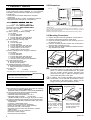
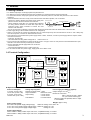
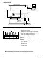
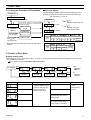
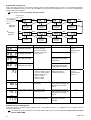
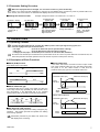
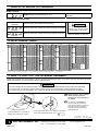
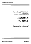
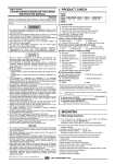
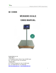
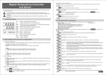
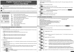
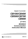
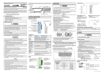
Digital Temperature Controller AE500 Instruction Manual IMAE01-E4 Thank you purchasing the RKC instrument. In order to achieve maximum performance and ensure proper operation of your new instrument, carefully read all the instructions in this manual. Please place this manual in a convenient location for easy reference. SYMBOLS WARNING : This mark indicates precautions that must be taken if there is danger of electric shock, fire, etc., which could result in loss of life or injury. CAUTION : This mark indicates that if these precautions and operating procedures are not taken, damage to the instrument may result. ! : This mark indicates that all precautions should be taken for safe usage. : This mark indicates important information on installation, handling and operating procedures. : This mark indicates supplemental information on installation, handling and operating procedures. : This mark indicates where information may be located. ! additional WARNING • An external protection device must be installed if failure of this instrument could result in damage to the instrument, equipment or injury to personnel. • All wiring must be completed before power is turned on to prevent electric shock, fire or damage to instrument and equipment. • This instrument must be used in accordance with the specifications to prevent fire or damage to instrument and equipment. • This instrument is not intended for use in locations subject to flammable or explosive gases. • Do not touch high-voltage connections such as power supply terminals, etc. to avoid electric shock. • RKC is not responsible if this instrument is repaired, modified or disassembled by other than factory-approved personnel. Malfunction can occur and warranty is void under these conditions. CAUTION This is a Class A instrument. In a domestic environment, this instrument may cause radio interference, in which case the user may be required to take adequate measures. All Rights Reserved, Copyright 1999, RKC INSTRUMENT INC. ® This instrument is protected from electric shock by reinforced insulation. Provide reinforced insulation between the wire for the input signal and the wires for instrument power supply, source of power and loads. Be sure to provide an appropriate surge control circuit respectively for the following: − If input/output or signal lines within the building are longer than 30 meters. − If input/output or signal lines leave the building, regardless the length. This instrument is designed for installation in an enclosed instrumentation panel. All high-voltage connections such as power supply terminals must be enclosed in the instrumentation panel to avoid electric shock by operating personnel. All precautions described in this manual should be taken to avoid damage to the instrument or equipment. All wiring must be in accordance with local codes and regulations. All wiring must be completed before power is turned on to prevent electric shock, instrument failure, or incorrect action. The power must be turned off before repairing work for input break and output failure including replacement of sensor, contactor or SSR, and all wiring must be completed before power is turned on again. To prevent instrument damage or failure, protect the power line and the input/output lines from high currents with a protection device such as fuse, circuit breaker, etc. Prevent metal fragments or lead wire scraps from falling inside instrument case to avoid electric shock, fire or malfunction. Tighten each terminal screw to the specified torque found in the manual to avoid electric shock, fire or malfunction. For proper operation of this instrument, provide adequate ventilation for heat dispensation. Do not connect wires to unused terminals as this will interfere with proper operation of the instrument. Turn off the power supply before cleaning the instrument. Do not use a volatile solvent such as paint thinner to clean the instrument. Deformation or discoloration will occur. Use a soft, dry cloth to remove stains from the instrument. To avoid damage to instrument display, do not rub with an abrasive material or push front panel with a hard object. Do not connect modular connectors to telephone line. NOTICE This manual assumes that the reader has a fundamental knowledge of the principles of electricity, process control, computer technology and communications. The figures, diagrams and numeric values used in this manual are only for purpose of illustration. RKC is not responsible for any damage or injury that is caused as a result of using this instrument, instrument failure or indirect damage. Periodic maintenance is required for safe and proper operation of this instrument. Some components have a limited service life, or characteristics that change over time. Every effort has been made to ensure accuracy of all information contained herein. RKC makes no warranty expressed or implied, with respect to the accuracy of the information. The information in this manual is subject to change without prior notice. No portion of this document may be reprinted, modified, copied, transmitted, digitized, stored, processed or retrieved through any mechanical, electronic, optical or other means without prior written approval from RKC. RKC INSTRUMENT INC. 2.2 Dimensions 9.2 (4)(5)(6)(7) / /Y * This power supply is used to light the LED of the SP400/SP500. Mounting brackets: 2 Mounting screws (with hexagon nuts): 2 Instruction manual (IMAE01-E4): 1 <Accessories> 2. MOUNTING 2.1 Mounting Cautions (1) This instrument is intended to be used under the following environmental conditions. (IEC61010-1) [OVERVOLTAGE CATEGORY II, POLLUTION DEGREE 2] (2) Use this instrument within the following ambient temperature and ambient humidity. • Allowable ambient temperature: 0 to 50 °C • Allowable ambient humidity: 5 to 395 %RH (Absolute humidity: MAX. W. C 29 g/m dry air at 101.3 kPa) (3) Avoid the following when selecting the mounting location. • Rapid changes in ambient temperature which may cause condensation. • Corrosive or inflammable gases. • Direct vibration or shock to the mainframe. • Water, oil, chemicals, vapor or steam splashes. • Excessive dust, salt or iron particles. • Excessive induction noise, static electricity, magnetic fields or noise. • Direct air flow from an air conditioner. • Exposure to direct sunlight. • Excessive heat accumulation. +0.6 0 45 91.8 110.8 +0.8 0 92 100 8.2 96 (8)(9) (10) (1) Input type: See 8. INPUT RANGE TABLE. (2) Range code: See 8. INPUT RANGE TABLE. (3) Power supply voltage 3: 24 V AC/DC 4: 100 to 240 V AC (4) Alarm 1 [ALM1], (5) Alarm 2 [ALM2] N: No alarm H: Process high alarm J: Process low alarm K: Process high alarm with hold action L: Process low alarm with hold action (6) Alarm 3 [ALM3] or Analog output N: No function H: Process high alarm J: Process low alarm K: Process high alarm with hold action L: Process low alarm with hold action 7: Analog output (0 to 20 mA DC) 8: Analog output (4 to 20 mA DC) (7) Alarm 4 [ALM4] or Power supply for LED drive N: No alarm H: Process high alarm J: Process low alarm K: Process high alarm with hold action L: Process low alarm with hold action P: LED drive power supply for SP400/SP500 * (8) Communication function N: No communication function 5: RS-485 (2-wire system) (9) Waterproof/dustproof construction N: No waterproof/dustproof construction 1: Waterproof/dustproof construction (10) Case color N: White A: Black 2 Close vertical mounting 1* L1 ∗ 92 44.8 (1) (2) (3) +0.8 0 30 48 AE500 Individual mounting (Unit: mm) Before using the product, check each of the following. If any of the products are missing, damaged, or if your manual is incomplete, please contact RKC sales office or the agent. • Model code • Check that all of the items delivered are complete. (See below) • Check that there are no scratch or breakage in external appearance (case, front panel, or terminal, etc). 25 1. PRODUCT CHECK +0.6 L1=(48×n-3) 0 n:Number of controllers (2 ≤n ≤6) *Rubber (Option) For mounting of the instrument, panel thickness must be between 1 to 10 mm. (When mounting multiple instruments close together, the panel strength should be checked to ensure proper support.) Waterproof and dustproof are not effective when instruments are closely spaced. 2.3 Mounting Procedures 1. Prepare the panel cutout as specified in 2.2 Dimensions. 2. Insert the instrument through the panel cutout. 3. Insert the mounting bracket into the mounting groove of the instrument. (Fig.1) 4. Push the mounting bracket forward until the bracket is firmly secured to the panel. (Fig.2) 5. The other mounting bracket should be installed the same way described in 3. and 4. Mounting bracket Fig.1 Fig.2 The waterproof/dustproof option on the front of the instrument conforms to IP65 when mounted on the panel. For effective waterproof/dustproof, the gasket must be securely placed between instrument and panel without any gap. If gasket is damaged, please contact RKC sales office or the agent. In addition, the mounting assembly also include two screws which can be used with the brackets to secure the instrument to the panel (Fig.3). Always use the hexagon nut and the screw attached to product. (2) Mounting screw When mounting the instrument by tightening screw Fig. 3 (1) Hexagon nut Insert the L-shaped hook of the mounting bracket into the groove. Then pull till click sounds to the direction shown by the arrow. When using the mounting screws, only turn one full revolution after the screw touches the panel. IMAE01-E4 3. WIRING 3.1 Wiring Cautions • For thermocouple input, use the appropriate compensation wire. • For RTD input, use low resistance lead wire with no difference in resistance between the three lead wires. • To avoid noise induction, keep input signal wire away from instrument power line, load lines and power lines of other electric equipment. • If there is electrical noise in the vicinity of the instrument that could affect operation, use a noise filter. - Shorten the distance between the twisted power supply wire Instrument power Twist these leadwires pitches to achieve the most effective noise reduction. Instrument IN OUT - Always install the noise filter on a grounded panel. Minimize power Noise filter terminals the wiring distance between the noise filter output and the Shorten distance between Minimize instrument power supply terminals to achieve the most pitches distance effective noise reduction. - Do not connect fuses or switches to the noise filter output wiring as this will reduce the effectiveness of the noise filter. • Power supply wiring must be twisted and have a low voltage drop. • About 5 to 6 seconds are required as preparation time for contact output every time the instrument is turned on. Use a delay relay when the output line, is used for an external interlock circuit. • This instrument is not furnished with a power supply switch or fuses. Therefore, if a fuse or power supply switch is required, install close to the instrument. - Fuse type: Time-lag fuse - Recommended fuse rating: Rated voltage 250 V Rated current: 1 A • For the current input specification, a resistor of 250 Ω (±0.02 % ±10 ppm, 0.25 W or more) must be connected between the input terminals. This resistor must be provided by the customer. • Use the solderless terminal appropriate to the screw size. - Screw size: M3 x 6 - Recommended tightening torque: 0.4 N m [4 kgf cm] • For an instrument with 24 V power supply, supply power from a SELV circuit. 3.2 Terminal Configuration Alarm 1/A larm 2 output term inals C om m unication term inals 13 14 SG 7 15 N O : N orm ally open T /R (A ) T /R (B ) 13 14 15 16 17 18 19 20 21 22 23 24 RS-485 8 NO 9 Input term inals NO A LM 2 11 A LM 1 R elay contact (O ption) 12 TC - + Pow er term inals 1 1 2 100- N 240 V L TC AC 2 3 4 5 6 7 8 Alarm 3 output term inals Alarm 4 output term inals 3 1 L 5 N 24 V 1 - NO A LM 3 3 + B 11 12 R elay contact Pow er supply term inals for LED drive DC 12 B RTD NO A LM 3 + Analog output term inals 2 11 A RTD 6 R elay contact 24 V 10 4 2 AC + 9 10 11 12 4 LE D 5 + - 6 AO IN 11 - - Voltage + 12 IN - C urrent C urrent 12 V D C Specifications Power consumption 7 VA max. (at 100 V AC) 10 VA max. (at 240 V AC) 5 VA max. (at 24 V AC) 160 mA max. (at 24 V DC) Analog output (Option) Number of output points: 1 point Output resolution: More than 10 bits Output rating: 0 to 20 mA DC 4 to 20 mA DC Load resistor: Less than 600 Ω Power supply for LED drive (Option) +1 V Output voltage: 12 V DC -2 V Number of connection: Max. 2 with the TF and 1 without TF. (TF: Transfer switch type) When this option is specified, alarm 4 output is not available. Weight: Approx. 250 g Power supply voltage 85 to 264 V AC (Power supply voltage range) 50/60 Hz Rating: 100 to 240 V AC 21.6 to 26.4 V AC (Power supply voltage range) 50/60 Hz Rating: 24 V AC 21.6 to 26.4 V DC (Power supply voltage range) Rating: 24 V DC Alarm output (Option) Alarm 1/Alarm 2: Relay contact output 250 V AC, 1A (Resistive load), 1a contact Alarm 3/Alarm 4: Relay contact output 250 V AC, 3A (Resistive load), 1a contact IMAE01-E4 3 3.3 Wiring Example RS-485 (2-wire system) Converter RS-232C AE500 Host computer 13 14 15 16 17 18 19 20 21 22 23 24 Alarmer SP400/ SP500 Alarmer Selector unit Alarmer 1 2 3 4 5 6 7 8 9 10 11 12 Measuring object Power supply 200 V AC 4. PARTS DESCRIPTION (1) Measured value (PV) display unit Displays measured value (PV). Displays various characters depending on the instrument. (1) ALM1 ALM2 ALM3 ALM4 SET (2) Alarm output indication lamps (ALM1 to ALM4) [Red] ALM1: Lights when alarm 1 output is turned on. ALM2: Lights when alarm 2 output is turned on. ALM3: Lights when alarm 3 output is turned on. (2) ALM4: Lights when alarm 4 output is turned on. (3) SET key Used for parameter calling up and set value registration. AE500 (3) (4) (5) (6) (4) Shift key Shift digits when settings are changed. Used when the character display in each mode is changed to the set value display. (5) DOWN key Decrease numerals. (6) UP key Increase numerals. To avoid damage to the instrument, never use a sharp object to press keys. 4 IMAE01-E4 5. SETTING 5.1 Calling-up Procedure of Each Mode ! Input type display This instrument immediately confirms input type following power on. Power on [Example] For a instrument with the K thermocouple input type and range from 0. to 1372 °C. Input type display Automatically (in 4 sec.) Power on The instrument returns to the PV display mode if no key operation is performed for more than one minute. PV display Indicates engineering unit Input type Alarm setting mode Press the SET key. Press the SET key for 2 sec. ]: [ a a [ b b PV display Parameter setting mode ]: Indicates input type (See following table) Display Communication Press the SET key setting mode * Input type < and key simultaneously. * Displayed when the instrument has the communication function. TC K J R S B E T N PL W5Re/ II W26Re Display Input type RTD TC U JPt 100 L Voltage (Current) Pt 100 5.2 Details of Each Mode Alarm setting mode !" This is the mode used to set the alarm (alarm 1 to alarm 4). The following parameter symbols are displayed one by one every time the SET key is pressed. For details, see the 5.3 Parameter Setting Procedure. PV display SET SET < SET Alarm 1 set value Symbol Name Alarm 1 setting AL1 Alarm 2 setting SET < SET Alarm 2 set value SET SET < SET Alarm 3 set value Setting (display) range Temperature input: −1999 to +9999 °C [°F] or −199.9 to +999.9 °C [°F] Voltage/current input: Same as input range < Alarm 4 set value SET Description Set the alarm 1 set value. Set the alarm 2 set value. SET : Press the SET key. <: Press the shift key. Factory set value Temperature input: 0 or 0.0 Voltage/current input: 0.0 AL2 Alarm 3 setting Set the alarm 3 set value. Not displayed when there is analog output. Alarm 4 setting Set the alarm 4 set value. Not displayed when there is power supply for LED drive. AL3 AL4 IMAE01-E4 5 !" Parameter setting mode This is the mode used to set the various parameters such as alarm differential gap, PV bias etc. The following parameter symbols are displayed one by one every time the SET key is pressed. (Press the SET key for 2 sec when enter parameter setting mode from PV display.) For details, see the 5.3 Parameter Setting Procedure. Press the SET key for 2 sec. SET PV display < SET : Press the SET key. <: Press the shift key. < SET SET SET < SET Symbol Set data lock function Name Alarm 1 differential gap setting AH1 Alarm 2 differential gap setting < SET Alarm 2 differential gap set value Alarm 1 differential gap set value SET SET < SET Alarm 3 differential gap set value < SET Analog output scale low set value Setting (display) range Temperature input: 0 to 100 °C [°F] or 0.0 to 100.0 °C [°F] Voltage/current input: 0.0 to 10.0 % SET Alarm 4 differential gap set value SET SET SET SET < < SET Analog output scale high set value PV bias set value Description Factory set value Set the alarm 1 differential gap. Temperature input: 2 or 2.0 Voltage/current Input: 0.2 Set the alarm 2 differential gap. AH2 Alarm 3 differential gap setting Set the alarm 3 differential gap. Not displayed when there is analog output Alarm 4 differential gap setting. Set the alarm 4 differential gap. Not displayed when there is power supply for LED drive. AH3 AH4 PV bias Temperature input: −1999 to +9999 °C [°F] or −199.9 to +999.9 °C [°F] Voltage/current input: −span to +span However, within −1999 to +9999 Sensor correction is made by Temperature input: 0 or 0.0 adding bias value to Voltage/current measured value (PV). Input: 0.0 Analog output scale high ALS to SLH (Setting limiter [high limit]) Sets high limit of the analog output range. Not displayed when there is no analog output. SLH Analog output scale low SLL (Setting limiter [low limit]) to AHS Sets low limit of the analog output range. Not displayed when there is no analog output. SLL Set data lock function 0: Can be changed 1: Can not be changed Selects the set data can be changed or can not be changed. 0 Pb AHS ALS LCK !" Communication setting mode This is the mode to conduct settings relating to the communication function. It is displayed for the instrument with the communication function. For details the protocol, identifiers and communication setting mode, see the separate Communication Instruction #). Manual (IMAE02-E# 6 IMAE01-E4 5.3 Parameter Setting Procedure When the displayed value is changed, it is not stored. To store it, press the SET key. After a new value has been displayed by using the UP and DOWN keys, the SET key must be pressed within one minute, or the new value is not stored and the display will return to the PV display. ! Change the Alarm set value Example: Change the Alarm 1 set value from 0 °C to 200 °C. (3) Shift the highlighted digit (2) (2) Set Set value value (1) Alarm 1 setting < Press the SET key to change to Alarm 1 setting (AL1) display. Press the key to Alarm 1 set value display. (4) Change the set value < Press the key to high-light the hundreds digit. The high-lighted digit indicates which digit can be set. (5) Store the set value Press the UP key to change the number 2. Press the SET key to store the new set value. The display returns to the next parameter. 6. OPERATIONS 6.1 Operating Cautions Connect the input signal wiring, and then turn ON the power. If the input signal wiring opens, the instrument judges the input is disconnected. Up-scale or downscale (To be specified when ordering) • TC input: Up-scale (Downscale when the input is shorted) • RTD input: • Voltage (current) input: Downscale (For 0 to 5 V DC or 0 to 20 mA DC, indefinite.) No influence is exerted upon the instrument for power failure of 20 ms or less. For power failure of more than 20 ms, the instrument performs the same operation as that at the time of power on after power recovery. 6.2 Description of Each Functions ! Alarm (ALM) function ! Alarm hold action Each alarm action is as follows. In the alarm hold action, the alarm function is kept invalid even if the measured value (PV) is in the alarm range when the power is on. The alarm function is held until the measured value (PV) goes out of the alarm state once. Process high alarm ( : Alarm setting) OFF ON High Low Process low alarm ( : Alarm setting) Measured value (PV) OFF ON High Low ! Alarm differential gap If measured value (PV) is close to the alarm set value, the alarm relay contact may repeatedly turn ON and OFF due to input fluctuations. If the differential gap is set, repeated turning ON and OFF of the relay contact can be prevented. Differential gap With alarm hold action Differential gap Measured value (PV) Alarm set value Alarm hold zone Alarm status OFF Without alarm hold action Measured value (PV) ON Low alarm set value OFF ON Measured value (PV) ON High alarm set value Alarm set value ! Set data lock (LCK) function The set data lock restricts parameter setting changes by key operation. This function prevents the operator from making errors during operation. Alarm status ON OFF ON Parameters protected by Set Data Lock function are still displayed for monitoring. IMAE01-E4 7 7. DISPLAY AT ERROR OCCURRENCE Error display Please contact RKC sales office or the agent. RAM failure (Incorrect set data write, etc.) Overscale and Underscale Measured value (PV) (Flashing) Measured value (PV) exceeds the input range. WARNING ! Overscale Measured value (PV) exceeds the high input display range limit. To prevent electric shock, always turn off the power before replacing the sensor. (Flashing) Underscale Measured value (PV) exceeds the low input display range limit. Check the Sensor or input lead. (Flashing) 8. INPUT RANGE TABLE Input type to to to 0 to 800 0 to 1000 0 to 1200 0 K to 200 400 600 1372 0 to 100 0 to 300 0 450 0 to to 500 0 to 800 0 0 to to 2502 20 to 70 J 1 0 0 0 1600 0 to 200 0 to 400 0 to 600 0 to 800 0 to 1000 0 to 1200 0 to 450 C C C C C C C C C C C F F F F C C C C C C C Model code K 01 K 02 K 03 K 04 J K 05 K 06 K 07 K 13 K 14 K A1 R S K A3 K A9 J 01 J 02 J 03 04 J J J 05 J 10 06 0 to 800 0 to 1600 0 to 2192 0 to 400 0 0 to 300 to 1600 0 K 17 K 20 K A2 Model code J A1 Input type B E 0 to 399 °C/0 to 799 °F : Accuracy is not guaranteed. to 0 to 1769 1350 0 to 3200 0 0 to to 3216 1600 0 0 to 1769 to 3200 0 400 to 3216 1800 to 0 to 1820 800 to 3200 0 to 3308 0 to 800 0 to 1000 0 0 2 to to 1600 1832 F F F F F C C C F F C C F F C C F F C C F F J A2 Model code Input type N 0 to 1200 0 to 1300 to 2300 to 2372 J A3 J A6 0 J A7 -199.9 to +400.0 1 R 01 -199.9 to +100.0 1 R 02 R 04 -100.0 to +200.0 1 0 0.0 1 R A1 1 R A2 -199.9 -100.0 350.0 to +752.0 to +200.0 1 S 01 -100.0 to +400.0 1 1 1 1 1 S 02 S A1 S A2 B 01 T 0.0 to 0.0 to to 0 W5Re/ to 2000 450.0 0 to 2320 W26Re 752.0 0 to 4000 B A1 0 to 1300 B A2 0 to 1390 B 02 E 01 PLⅡ 0 to 1200 E 02 0 to 2400 E A1 0 to 2534 E A2 -199.9 to +600.0 C N C N F N F N C2 T C2 T C T C T 2 F T F T F T F T F T C W C W F W C A C A C A F A F A 2 C U Input type 01 -199.9 02 0.0 U A1 A2 01 02 03 L 04 to +100.0 to 400.0 -199.9 to +999.9 -100.0 0.0 to +200.0 to 999.9 0 to 400 0 to 800 0 to 0 to 1600 800 A1 A2 -199.9 to + 649.0 A3 -199.9 to +200.0 to + 50.0 to +100.0 to + 200.0 A4 -100.0 A5 -100.0 01 02 -100.0 0.0 Pt100 A1 0.0 0.0 0.0 01 02 to 50.0 to to 100.0 to 200.0 300.0 to 500.0 03 0.0 A1 -199.9 to + 999.9 A2 -199.9 to + 400.0 01 -199.9 to + 200.0 -199.9 to -100.0°C/-199.9 to -158.0 °F : Accuracy is not guaranteed. 3 C2 C F2 F F C C F F C C C C C C C C C C F F F Model code U 02 U A2 to +100.0 -100.0 to + 300.0 0.0 to 100.0 -100.0 U 03 U A1 Model code Input type Pt100 U A3 L 01 0.0 to 0.0 to 400.0 0.0 to 500.0 200.0 L 02 -199.9 to +649.0 L A1 -199.9 to L A2 -100.0 to D 01 D 02 -100.0 to -100.0 to +200.0 + 50.0 +100.0 +200.0 JPt100 D 03 D 04 0.0 to 50.0 0.0 to 100.0 D 05 0.0 to 200.0 D 06 0.0 to 0.0 to 300.0 D 07 D 08 D 09 D 10 D A1 D A2 0 to 0 to 1 to 5 V DC 10 V DC 3 5 V DC 0 to 20 mA DC 4 to 20 mA DC 500.0 F F F F F F C C C C C C C C C C D A4 D A5 D A6 D A7 D A8 D A9 P 01 P 02 P 03 P 04 P 05 P 06 P 07 P 08 P 09 P 10 4 01 0.0 to 5 01 6 01 100.0 7 01 8 01 D A3 Z-1010 specification 9. HOW TO PULL OUT THE INTERNAL ASSEMBLY Usually, this instrument is not necessary to remove the internal assembly from the case. When removing the internal assembly without disconnecting the external wiring, take the following steps. ! WARNING To prevent electric shock or instrument failure, only qualified personnel should be allowed to remove the internal assembly. To prevent electric shock or instrument failure, the power must be turned off before removing internal assembly. To prevent injury or instrument failure, do not touch the printed wiring boards when removing the internal assembly. Apply pressure very carefully when removing internal assembly to avoid damage to the frame. To conform to IEC61010-1 requirements for protection from electric shock, the internal assembly of this instrument can only be removed with an appropriate tool. Lock (Left side/right side) Unlock using such a screwdriver. Gently press outside on handle. • Recommended tool: Blade screwdriver • Recommended blade width: 6 mm The first edition: AUG. 1999 The fourth edition: JUN. 2003 [IMQ00] ® RKC INSTRUMENT INC. IMAE01-E4 HEADQUARTERS: 16-6, KUGAHARA 5-CHOME, OHTA-KU TOKYO 146-8515 JAPAN PHONE: 03-3751-9799 (+81 3 3751 9799) E-mail: [email protected] FAX: 03-3751-8585 (+81 3 3751 8585) JUN. 2003