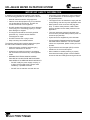
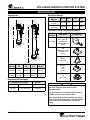
1
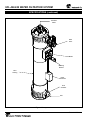
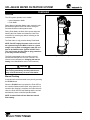
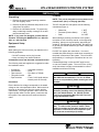
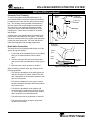
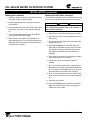
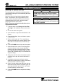
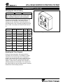
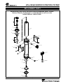
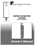
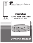
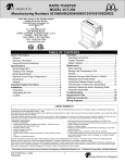
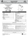
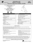
Manufacturing
Numbers:
9700465
9700475
Water filtration
system
System Tested and Certified by NSF
International and WQA against NSF/ANSI
Standard 42 and 53 for the reduction of:
UFL-420/440 Series
Standard No. 42: Aesthetic Effects
Nominal Particulate Reduction Class I
Standard No. 53: Health Effects
Cyst Reduction
Turbidity Reduction.
P/N 1011055 11/09
Owner ’s Manual
UFL-420/440 water Filtration system
Table of contents
Owner Information......................................................2
General.......................................................................2
Warranty Information..................................................2
Service/Technical Assistance.....................................3
Important Safety Information.....................................4
Specifications..............................................................5
Dimensions.................................................................5
Replacement Cartridges.............................................5
Electrical Ratings........................................................5
Electrical Cord & Plug Configurations........................5
Performance Data Sheet.............................................7
Ultra Filter Cartridge Capacities.................................7
System Capacities......................................................7
Performance Claims for Percent Reduction...............7
Overview......................................................................8
Overview.....................................................................8
Manual Flushing.........................................................8
Installation....................................................................9
Unpacking...................................................................9
Equipment Setup........................................................9
Flow Regulator Assembly.........................................10
Mounting the System................................................10
Inlet Water Plumbing................................................10
Permeate Line Plumbing..........................................11
Drain Valve Connection............................................11
Starting the Controller..............................................12
Rinsing the Ultra Filter Cartridge..............................12
Sanitizing the System and Lines..............................13
Maintenance...............................................................14
Replacing the Ultra Filter Cartridge..........................14
System Sanitization..................................................14
Changing the Interval Setting...................................15
Resetting the Timer Program...................................15
Troubleshooting........................................................16
Replacement Parts ...................................................17
Notes..........................................................................19
Limited Warranty.......................................Back Cover
Owner Information
General
Warranty Information
Antunes Filtration Technologies, Division of A.J.
Antunes & Co., has partnered with companies from
around the globe to produce the UFL Series water
filtration systems. The UFL Series reduces cysts and
turbidity that can enter a typical water supply. This patented technology is now available to you, sized for your
particular application. All filter configurations utilize
NeoH capillary membranes, providing the latest innovation in reusable surface filtration technology.
Please read the full text of the Limited Warranty in this
manual.
This manual provides the safety, installation and
operating procedures for the UFL Series water filtration
systems. We recommend that all information contained
in this manual be read prior to installing and operating
the unit.
• Damages caused in shipment or damage as
result of improper use.
If the unit arrives damaged, contact the carrier immediately and file a damage claim with them. Save all
packing materials when filing a claim. Freight damage
claims are the responsibility of the purchaser and are
not covered under warranty.
The warranty does NOT extend to:
• Installation of electrical service.
• Normal maintenance as outlined in this manual.
Your UFL Series unit is manufactured from the finest
materials available and is assembled to AFT’s strict
quality standards. This unit has been tested at the
factory to ensure dependable trouble-free operation.
• Malfunction resulting from improper maintenance.
• Damage from moisture leaking into electrical
components.
• Normal maintenance as outlined in this manual.
• Damage from tampering with, removal of, or
changing any preset control or safety device.
Important! Keep these instructions for future reference. If the unit changes
ownership, be sure this manual accompanies the equipment.
2
P/N 1011055 11/09
UFL-420/440 water filtration system
Owner information (continued)
Service/Technical Assistance
Suggested replacement period for Ultra Filter Cartridge
is approximately 3 years.
If you experience any problems with the installation
or operation of your unit, contact Antunes Filtration
Technologies at 1-630-784-1000, or toll free in the
United States at 1-800-253-2991.
For sales in the state of Iowa:
Fill in the information in the next column and have it
handy when calling for assistance. The serial number
is on the specification plate located on the unit.
Seller:
Date:
Buyer:
Date:
Purchased From:
Date of Purchase:
Model No.:
Serial No.:
Mfg. No.:
Important
A.J. Antunes and Co. reserves the right to change specifications and product design without
notice. Such revisions do NOT entitle the buyer to corresponding changes, improvements,
additions or replacements for previously purchased equipment.
P/N 1011055 11/09
3
UFL-420/440 water Filtration system
Important Safety Information
In addition to the warnings and cautions in this manual,
use the following guidelines for safe operation of the unit:
• If the supply cord is damaged, it must be replaced
by the manufacturer or its service agent or a similarly qualified person.
• Read all instructions before using equipment.
• This equipment is to be installed to comply with the
local plumbing code and any other applicable code.
• Install or locate the equipment only for its intended
use as described in this manual. Do NOT use
corrosive chemicals in this equipment.
• Water pressure must not exceed 100 psig (690
kPa). To reduce water pressure, install a water
pressure regulator and set water pressure to suit
application.
• Do NOT operate this equipment if it has a damaged
cord or plug; if it is not working properly, or if it has
been damaged or dropped.
• The trans membrane pressure (inlet water pressure minus the permeate water pressure) must not
exceed 45 psi (310 kPa).
• This equipment should be serviced by qualfied
personnel only. Contact Antunes Filtration
Technologies for repair.
• System should be supplied only with cold water.
• Do NOT immerse cord or plug in water.
•Commonwealth of Massachusetts Plumbing Code
248 CMR shall be adhered to. The use of saddle
valves are not permitted, please consult your local
plumber.
• Keep cord away from heated surfaces.
The following warnings and cautions appear throughout
this manual and should be carefully observed:
• Unplug the power cord before performing any
service or maintenance on the unit.
• A ground fault circuit interrupter (GFCI) must be
installed on the circuit to this system
• All electrical connections must be in accordance
with local electrical codes and any other applicable
codes.
• When installed on metallic plumbing, a properly
sized electrical bonding jumper must be installed
across the inlet and outlet pipes serving this device.
• Warning electrical shock hazard.
Failure to follow these instructions
could result in serious injury or death.
- Do NOT modify the power supply cord plug. If
it does not fit the outlet, have a proper outlet
installed by a qualified electrician.
- Do NOT use an extension cord with this unit.
4
P/N 1011055 11/09
UFL-420/440 water filtration system
Specifications
Dimensions
Electrical Ratings
UFL-420
UFL-440
B
B
Model &
Mfg. No.
Voltage Watts
UFL-420
9700465
100–240
UFL-440
9700475
100–240
Amps
Hertz
10
0.4
50/60
10
0.4
50/60
Electrical Cord & Plug Configurations
A
A
C
Kit Model
Number
Description
0012146
DC Power Supply
100 - 240 VAC
Includes the
4 plug adaptors
below
Configuration
NOTE: PLUG STYLE
MAY VARY
US
NEMA 1-15 (2 pin)
or NEMA 5-15
(3 Pin)
Euro
CEE 7/16
C
Model &
Mfg. No.
Height
(A)
Width
(B)
Depth
(C)
Operating
Weight
UFL-420
9700465
28”
(71 cm)
11.5”
(29 cm)
6”
(15 cm)
28 lbs.
(12.7 kg)
UFL-440
9700475
47”
(119 cm)
11.5”
(29 cm)
6”
(15 cm)
42 lbs.
(19 kg)
AS/NZS
3112
AUS
(2 Pin)
UK
BS 1363
Replacement Cartridges
Replacement Cartridge
Part No.
UFL-420
L-420 Ultra Filter
7000411
UFl-440
L-440 Ultra Filter
7000412
US
NEMA 1-15 (2 PIN)
or NEMA 5-15
(3 PIN)
EURO
CEE 7/16
AS/NZS 3112
AUS
(2 PIN)
UK
BS 1363
Caution
All electrical connections must be in accordance
with local electrical codes and any other
applicable codes.
A ground fault circuit interrupter (GFCI) must be
installed on the circuit to this system.
When installed on metallic plumbing, a properly
sized electrical bonding jumper must be installed
across the inlet and outlet pipes serving this
device
P/N 1011055 11/09
5
UFL-420/440 water Filtration system
Specifications (continued)
Permeate
Outlet
Drain
Valve
Flush Button
Mounting
Bracket
Filter
Housing
Power
Transformer
Flow
Controller
Inlet
Figure 1. Components
6
P/N 1011055 11/09
UFL-420/440 water filtration system
Performance Data Sheet
Ultra Filter Cartridge Capacities
Max.Operating Pressure
Max. Operating Temp.
Min. Operating Temp.
Max. Trans Membrane Pressure
pH Range
MWCO System Tested and Certified by NSF
International against NSF/ANSI
Standard 42 and 53 for the reduction of:
100 psig (690 kPa)
104°F (40°C)
40°F (4°C)
45 psi (3.1 bar)
3-10
100 kD
Standard No. 42: Aesthetic Effects
Nominal Particulate Reduction Class I
Standard No. 53: Health Effects
Cyst Reduction
Turbidity Reduction
System Capacities
Model &
Mfg. No.
Capacity
Per Min.
UFL-420
9700465
4.6 gal.
(17 liters)
UFL-440
9700475
9.2 gal.
(35 liters)
This system has been tested according to NSF/ANSI
Standard 42 and 53 for reduction of the substances
listed below. The concentration of the indicated substances in water entering the system was reduced to a
concentration less than or equal to the permissible limit
for water leaving the system, as specified in NSF/ANSI
42 or 53. While testing was performed under standard
laboratory conditions, actual performance may vary.
Performance Claims for Percent Reduction
Influent
Challenge
Concentration
Reduction
Requirement
Minimum
Percent
Reduction
cyst
minimum
50,000/L
99.95%
99.95%
Turbidity
11+/1 NTU
≤ 0.5 NTU
97.3%
Particulate Class I
Particles 0.5 to <
1µm
at least 10,000
particles /mL
85%
N/A
Substance
1
1based on the use of microspheres or Cryptosporium parvum oocysts
P/N 1011055 11/09
7
UFL-420/440 water Filtration system
Overview
Overview
The UFL system operates in two modes:
• Normal Operation Mode
• Flush Mode
During Normal Operation Mode, water enters the Inlet
and flows through the Ultra Filter before exiting the
Permeate Outlet as usable product water.
During Flush Mode, the Drain Valve opens and water
entering the Inlet flushes and cleans the Ultra Filter
membrane by removing any debris collecting on the
membrane wall.
The Drain Valve is only powered during Flush Mode.
NOTE: Do NOT unplug the power cord or turn off
the system during Flush Mode. If there is a power
outage or the system is unplugged, water will continue to be filtered but the system will NOT flush.
This could cause the Ultra Filter to plug prematurely and may void the warranty.
Figure 2. UFL-420 System
The flush is automated by the controller to last 10
seconds and take place in one hour intervals. This
interval can be changed (see Changing the Interval
Setting in the Maintenance section of this manual).
Caution
Changing the flush interval can cause the Ultra
Filter to plug prematurely and may void the warranty. Consult the factory for more information.
Manual Flushing
A manual flush can be activated at any time by pressing
the FLUSH button.
When the FLUSH button is pressed, the Flush LED on
the controller flashes and the Drain Valve opens for 10
seconds. After flushing is complete, the Drain Valve will
close, the Flush LED will stop flashing and the unit will
automatically return to Normal Operation Mode.
NOTE: A manual flush will not affect the interval
flush setting.
8
P/N 1011055 11/09
UFL-420/440 water filtration system
Installation
Unpacking
Plumbing
1. Remove the system and all packing materials
from the shipping carton.
NOTE: This unit is designed to use tap water not to
exceed 100°F (38°C) or 100 psig (690 kPa).
2. Remove all packing materials and protective coverings from the system
The UFL-420 and UFL-440 systems use the following
connections (Figure 1):
3. Remove the information packet. To prevent any
delay in obtaining warranty coverage, fill out and
mail the warranty card.
NOTE: If any parts are damaged, contact Antunes
Filtration Technologies IMMEDIATELY at 1-800-2532991 or 1-630-784-1000.
Water Inlet Permeate (Product Water)
Drain
1” NPT
1” NPT
3/4” NPT
When making a plumbing connection to the system,
remember to use a back-up wrench on the supporting
plumbing. Always use a good quality, approved pipe
sealant or Teflon® tape on pipe threads. Be careful not
to get the pipe sealant inside the pipe when making the
connections.
Equipment Setup
General
When placing the unit into service, pay attention to the
following guidelines:
Do NOT over tighten the connections. It is recommended that plastic fittings be used when connecting to
the plastic connections of the system. This will reduce
the possibility of cracking the connections due to overtightening.
• Do NOT immerse cord or plug in water.
• Keep cord away from heated surfaces.
Suggested Tools and Supplies for Installation
If soldered plumbing is used, do NOT apply heat to,
or near, the filtration system. The use of union (O-ring
seal) connections is highly recommended for ease of
installation and future servicing.
The following tools and supplies are suggested to make
the installation easier:
• Screwdriver
• Drill with bits
• Tape measure
• Two gallon bucket
• Pipe wrenches
•
•
•
• Adjustable wrenches
•Level
• Pipe dope or Teflon® tape
• Fresh 5 1/4% liquid chlorine bleach (such as Clorox®)
IMPORTANT
Electrical
Commonwealth of Massachusetts Plumbing Code
248 CMR shall be adhered to. The use of saddle
valves are not permitted, please consult your local
plumber.
Ensure that the line voltage corresponds to the stated
voltage on the units specification label. Make sure that
the plug on the power cord from the system and the
outlet match. For proper operation, and to ensure the
highest quality water from the system, make sure that
the system is not connected to a switched electrical
outlet.
Caution
This equipment is to be installed to comply with
the basic plumbing code of the Building Officials
and Code Administrators, Inc. (BOCA) and the
Food Service Sanitation Manual of the Food and
Drug Administration (FDA).
Caution
Water pressure must not exceed 100 psig (690
kPa). To reduce water pressure, install a water
pressure regulator and set water pressure to suit
application. Note that the trans membrane pressure must not exceed 45 psi (310 kPa).
P/N 1011055 11/09
9
UFL-420/440 water Filtration system
Flow Regulator Assembly
Installation (continued)
Inlet Water Plumbing
Your filtration system uses a water Flow Regulator
Assembly that controls the flow of water into the unit.
This assembly consists of a white threaded male connector and a color-coded Flow Regulator (Figure 3).
The unit MUST be operated with the appropriate Flow
Regulator Assembly.
•
UFL-420 Units: Use a GREEN and WHITE Flow
Regulator Assembly (5 gallons per minute).
•
UFL-440 Units: Use a BLACK and WHITE Flow
Regulator Assembly (10 gallons per minute).
The Inlet water plumbing line should be 1” NPT or
larger. A shutoff valve (not supplied) should be installed
in the line leading to the system. The valve should be
mounted close to the system inlet and sized properly for
the inlet plumbing line.
An optional “T” or Cross Fitting with cap or plug can be
installed between the Inlet Valve and the System Inlet.
This fitting can be used for draining and sanitizing the
system and downstream plumbing.
The system should only be connected to the cold water
line.
Caution
Flow Regulator Assemblies are NOT interchangeable. Operating the system with the wrong Flow
Regulator or without a Flow Regulator can damage the system, cause personal injury, and
will void the warranty!
Before connecting the fitting to the System Inlet, the
plumbing to the system must be flushed clear of all
debris. Hold a bucket at the inlet water line and slowly
open the Inlet Water Valve. Allow the pipe to flush until
all debris is removed.
INSET
Mounting the System
Water Flow
The UFL system comes with a Mounting Bracket to
mount the system securely. When mounting the system,
pay attention to the following guidelines:
•
Into
Filter
Base
Note the location of the water supply, drain, and
an appropriate electrical outlet when choosing a
mounting location.
•
Allow sufficient access for cartridge replacement.
The UFL-420 system should be mounted with 20
inches below the unit to allow proper access when
changing cartridges. The UFL-440 system should
be mounted with 40 inches below the unit.
•
Mount the system near but NOT above an appropriate electrical outlet.
•
Do NOT mount the system above any electrical
equipment or items that may be damaged if they
get wet.
•
Mount the system near a drain for flushing operations.
•
Mount the system before all consumable water
filtration processes.
•
Secure the Mounting Brackets into wall studs or
with the appropriate heavy duty mounting hardware.
Flow Controller
(Green for UFL-420,
Black for UFL-440)
Sanitation
Plug (not
supplied)
Flow Control
(supplied,
see inset)
Filter
Base
Inlet Water
Valve (not
supplied)
Incoming
Water
Supply
Inlet Drain
Valve (not
Supplied)
Figure 3. Inlet Water Plumbing
The system is pre-assembled to Mounting Brackets.
The Mounting Brackets have mounting holes secure the
bottom of the system to the wall.
10
P/N 1011055 11/09
UFL-420/440 water filtration system
Installation (continued)
Permeate Line Plumbing
Secure
End
To ensure the highest quality and safest water, it is
recommended that a check valve (to prevent backflow)
be installed in the water line after the permeate connection. This will help prevent possible contamination of
the filter system due to other equipment downstream.
The check valve (not supplied) should be mounted
close to the system outlet, and sized properly for the
plumbing line. Check with local codes for the proper
specification.
2” (5.1 cm)
minimum
Standpipe
A shutoff valve (not supplied) should be installed in the
filtered water line leading from the system. The valve
should be mounted close to the system outlet and sized
properly for the plumbing line. This valve will allow for
easier servicing and future cartridge replacement.
Drain
Drain Line
from System
Drain Valve Connection
The drain hose is for flushing particle buildup out of the
system during self cleaning.
Secure
End
1. Cut a length of the provided 20-foot coil of braided
tubing so it reaches the drain from the Drain
Valve.
Floor
Drain
2. Connect one end of the hose to the Drain Valve
and secure it with a provided Worm Clamp (Figure
4).
3. Direct the other end of the hose to the drain.
2” (5.1 cm)
minimum
Figure 4. Proper Drain Plumbing
When connecting the drain hose, pay attention to the
following guidelines:
• The drain line plumbing must be able support the
flow rate whenever the system flushes. This flow
rate is dependent on the inlet water pressure, inlet
pipe size, and system.
• The drain line leading out of the system must be
as short as possible and slope downwards without
any kinks or loops.
• The drain line plumbing must be position and
secured at least 2 inches above the drain (Figure
4). This air gap protects the system from contamination in the event of a backed-up drain.
• The drain used must not be blocked or restricted.
• The drain used must be as large or larger than
the drain line plumbing.
P/N 1011055 11/09
Drain Line
from System
11
UFL-420/440 water Filtration system
Installation (continued)
Starting the Controller
Rinsing the Ultra Filter Cartridge
1. Select the proper AC plug for your electrical outlet
and install it onto the power supply.
The Ultra Filter Cartridge must be rinsed before the system is used to remove any air and protective solution.
2. Plug the appropriate end of the power cord into
the controller.
Caution
Ingesting the protective solution may cause irritation of the gastrointestinal tract, colic, diarrhea, or
other similar symptoms.
3. Plug the other end of the power cord into the electrical outlet. The LEDs on the controller will light
up.
1. Direct water from the Permeate Outlet to a drain.
4. The controller automatically enters Flush Mode
and the Flush LED starts to flash.
2. Open the tap or faucet closest downstream to the
filter system.
5. When flushing is complete, the Flush LED will
stop flashing and one or more LEDs will remain lit,
indicating the unit has power and which interval is
selected in the controller.
3. Slowly open the inlet water valve and allow water
to enter the system.
4. Press the FLUSH button. The Drain Valve will
open and air and water will come out of the drain
line. Repeat six times to ensure all air and storage solution are flushed out of the Ultra Filter
Cartridge.
5. Allow water to continue to run through the system
and out the faucet for 15 minutes.
6. Inspect the unit for any leaks and repair as
needed.
7. After 15 minutes with water flow, close the tap or
faucet and let the system stand without water flow
for 15 minutes to allow trapped air to come out of
the hollow fibers of the Ultra Filter Cartridge.
8. After 15 minutes without water flow, open the tap
or faucet for five minutes to flush out the trapped
air.
9. Close the tap or faucet.
10. Press the FLUSH button to open the Drain Valve.
Repeat six times to ensure any remaining air is
flushed out of the system.
12
P/N 1011055 11/09
UFL-420/440 water filtration system
Installation (continued)
Sanitizing the System and Lines
IMPORTANT
Commonwealth of Massachusetts Plumbing Code
248 CMR shall be adhered to. The use of saddle
valves are not permitted, please consult your local
plumber.
The plumbing must be sanitized to eliminate possible
contamination that may have occurred during the installation process.
One ounce (30 ml) of liquid chlorine bleach (regular
bleach, unscented 6% sodium hypochlorite) can be
used to sanitize the plumbing. The amount of bleach
needed depends on the system and the amount of
plumbing downstream of the system.
Caution
Ingesting the protective solution may cause irritation of the gastrointestinal tract, colic, diarrhea, or
other similar symptoms
NOTE: Follow the handling and safety instructions
supplied with the bleach.
1. Follow the steps in the Rinsing the Ultra Filter
Cartridge in the Installation section of this manual.
2. Turn off the water to the system.
3. Open the faucet or tap closest downstream to the
system.
4. Close the Inlet Water Valve and allow the system
to depressurize.
5. Place a bucket under the “T” or cross fitting at
the inlet connection to the system. Open the inlet
drain valve or unscrew the cap to drain the system.
6. Press the FLUSH button to help drain the system.
7. When the water flow out of the inlet fitting stops,
close the inlet drain valve and pour the liquid
bleach into the inlet connection fitting. Be careful
not to spill bleach onto clothing or skin. You may
want to add the bleach using a cup. Reattach the
cap on the fitting.
8. Slowly open the inlet water valve and allow water
to flow out of the tap until the smell of bleach is
present.
9. Immediately close the tap and let the system
stand with no water flow for at least 15 minutes to
allow the bleach to sanitize the pipes.
10. After 15 minutes without water flow, open the tap
and flush until the presence of bleach is gone. All
other taps should be opened to flush any bleach
from the plumbing. Close the taps.
11. Press the FLUSH button to complete the flushing
process.
P/N 1011055 11/09
13
UFL-420/440 water Filtration system
Maintenance
Replacing the Ultra Filter Cartridge
1. Turn off water to the system by closing the inlet
valve.
2. Press the FLUSH button to flush the system and
relieve pressure. Repeat several times.
3. Place a bucket under the “T” or cross fitting at the
inlet connection to the system. Open the valve or
unscrew the cap to drain the system.
Ultra Filter
Cartridge
NOTE: Make sure there is enough room next to the
system to remove the cartridge.
4. Close the inlet drain valve or reattach the cap on
the “T” fitting when the water flow stops.
5. Unplug the system.
6. Remove the Snap Ring from the Ultra Filter
Housing. Grab the raised lug with a pair of pliers
and pull towards the center of the End Cap and
away. The Snap Ring should lift out of its groove.
Cartridge
O-Ring
End Cap
O-Rings
7. Remove the End Cap, End Cap O-ring, and
Cartridge from the housing (Figure 5).
NOTE: If the Cartridge does not easily come out
of the Housing, remove the opposite End Cap for
assistance.
End Cap
8. Inspect the Large End Cap O-rings and End Cap
O-ring for nicks or cuts. Replace as needed.
Snap Ring
Figure 5. Replacing the Ultra Filter Cartridge
9. Lubricate all O-rings with a food-grade silicone
lubricant. Apply a light coating of lubricant to the
inside center tube at both ends of the new cartridge.
NOTE: Make sure that the Snap Ring is fully seated
before turning the water on.
15. Rinse the new Ultra Filter Cartridge before
placing the system back into operation. Follow
the Rinsing the Ultra Filter Cartridge and
Sanitizing the System and Lines procedures in
the Installation section of this manual to complete
the cartridge change.
10. Record the serial number of the new cartridge.
The cartridge serial number is engraved on one
end of the outer tube (for example: 05K 12013).
11. Install the End Cap O-ring on the End Cap and
insert the Large End Cap into the end of the new
cartridge.
16. When rinsing is complete, repressurize the
system.
12. Position the new cartridge and End Cap at the
housing and gently insert into the housing.
System Sanitization
13. Press the End Cap into position until it is fully
seated and the Snap Ring groove is visible.
The system and downstream plumbing should be sanitized at least once a year. When necessary, follow the
procedure in Sanitizing the System and Lines in the
Installation section of this manual.
14. Install the Snap Ring by guiding the non-lugged
end into the groove first, pushing outward and
working around the ring until it snaps into place.
14
P/N 1011055 11/09
UFL-420/440 water filtration system
maintenance (continued)
Changing the Interval Setting
Caution
Changing the flush interval can cause the Ultra
Filter to plug prematurely and may void the warranty. Consult the factory for more information.
Though not recommended, the Interval Setting on the
controller can be changed. If the setting must be
changed, use the chart below. Press and hold the corresponding button. After 5 seconds, the Button LED will
turn on. After 10 seconds, the Flush LED will also turn
on.
Flush
Interval
Button
Hold Time
Button
LED
Flush
LED
15 minutes
A
10 seconds
On
On
30 minutes
B
10 seconds
On
On
45 minutes
C
10 seconds
On
On
1 hour
A
5 seconds
On
Off
4 hour
B
5 seconds
On
Off
6 hours
C
5 seconds
On
Off
12 hours
D
5 seconds
On
Off
24 hours
D
10 seconds
On
On
Figure 6. Controller
Resetting the Timer Program
During the normal operation, the system will flush
according to the set interval. It is possible the system
will flush at a time of high water use. If this poses a
problem, the controller can be reset. Unplug the power
supply, wait for 5 seconds, and then plug the power
supply in. When power is restored to the controller, it
will automatically enter Flush Mode. The controller will
then begin timing from the point when power is restored
based on the interval setting selected.
P/N 1011055 11/09
15
UFL-420/440 water Filtration system
Troubleshooting
Problem
Possible Cause
Corrective Action
Unit does not have power.
The power cord is not correctly
plugged in.
Plug power cord in correctly.
The Control Display is blank.
The power cord is not correctly
plugged in.
Plug power cord in correctly.
Control Board is inoperable.
Transformer is inoperable.
Contact your maintenance person or
Authorized Service agency.
Inlet Valve closed
Open the Inlet Valve
Inlet Strainer is plugged
Clean/replace Inlet Strainer
End of the capillaries plugged
Clean/replace Filter Cartridge
See above.
See above.
The system may be in a flush cycle.
Wait for the flush cycle to end.
Flushing program not set correctly
for water conditions.
Decrease the flush interval (refer to the
Operation section of this manual).
Drain Valve is stuck open.
Replace/rebuild the Drain Valve.
The inlet water pressure is too low.
Boost the inlet water pressure/replace
pipes.
Storage/shipping solution not completely rinsed out of system.
Rinse system for a longer period of time.
Biological growth in pipes.
Sanitize plumbing.
Water conditions changed.
Consider installing taste and odor filtration.
Broken capillary in Filter Cartridge.
Replace Filter Cartridge.
Drain Valve stuck open.
Replace/rebuild the Drain Valve.
Controller sending continuous signal
to valve.
Replace the controller.
Flush occurs at time of high
water usage.
The Flush Interval is set to interfere
with water use.
Change Flush Interval. Unplug unit and
plug in at a time of lower water usage.
Water splashes at drain during flush.
Drain line not positioned properly.
Reposition the end of the drain line.
Water leaks at the ends of the
Filter Cartridge after changing
cartridges.
Cartridge end connections are not
tight enough.
Tighten with wrench if necessary.
O-rings not lubricated.
Lubricate O-rings with food-grade lubricant.
O-rings are split, cut, or twisted
Replace O-rings.
Permeate port is not tight enough
Tighten, with wrench if necessary.
O-ring not lubricated.
Lubricate O-ring with food-grade lubricant.
O-ring split, cut, or twisted.
Replace O-ring.
Fitting broken or loose.
Retighten or replace the fitting.
Not enough pipe thread sealant
used.
Redo the fitting with the proper amount of
sealant.
No water comes out of the filter system
Low water flow/pressure out
of system
Water tastes bad.
Flush runs continuously.
Water leaks from Permeate
port.
Water leaks from system fitting or connection.
16
P/N 1011055 11/09
UFL-420/440 water filtration system
Replacement Parts
Replacement Parts can be purchased from an authorized dealer. Contact
Antunes Filtration Technologies at 1-630-754-1000 or toll free in the
United States at 1-800-253-2991
1
2
8
3
4
13
5
11
12
6
7
9
14
10
6
2
5
4
3
16
P/N 1011055 11/09
17
15
UFL-420/440 water Filtration system
Replacement Parts (continued)
Replacement Parts can be purchased from an authorized dealer. Contact Antunes
Filtration Technologies at 1-630-754-1000 or toll free in the United States at 1-800-253-2991
Item
1
2
3
4
5
6
7
8
Part
No.
2190150
2190147
2180181
2180228
7000413
0200235
0200236
2140153
0504065
3080157
7000411
7000412
Description
Qty.
Union Adaptor, 1” NPT
Nipple, Hex 1” NPT
Ring, Lock
Cap, End 1” Port
O-Ring Replacement Kit
O-Ring, End Cap
O-Ring, Cartridge
Lubricant, High Vacuum Grease
Clamp, 4” Filter
Screw, Tap 8-32 x 3/8” Lg.
Cartridge Replacement Kit UFL-420
(Includes O-Ring Replacement Kit)
Cartridge Replacement Kit UFL-440
(Includes O-Ring Replacement Kit)
Item
9
Part
No.
2180201
2180202
10 0021338
0021337
11 2070117
12 4040189
13 0504279
14 0012357
15 0012146
16 2190148
17* 2140158
18* 0700769
1
2
2
2
1
2
4
1
1
4
1
Description
Qty.
Filter Housing, UFL-420
Filter Housing, UFL-440
5 GPM Flow Reg. Assy, UFL-420
10 GPM Flow Reg. Assy, UFL-440
Nipple, 3/4” NPT
Solenoid Valve, NC 3/4” NPT
Bracket, Mounting
Universal Pulse Controller
Power Adapter Assembly
Plug, Pipe 1” NPT
Cord, Loctite Thread Sealing
Wire Harness
1
1
1
1
1
1
1
1
1
1
1
1
1
*not shown
18
P/N 1011055 11/09
UFL-420/440 water filtration system
Notes
P/N 1011055 11/09
19
LIMITED WARRANTY
Equipment manufactured by Antunes Filtration Technologies, a Division of A.J. Antunes & Co., has been constructed of the finest materials available and manufactured to highest quality standards. These units are warranted to be free from defects in material and workmanship for a period of on year from date of purchase under
normal use and service, and when installed in accordance with the manufacturer’s recommendations.* The ultra
filtration membrane cartridge is warranted under the same terms and conditions on a pro rated basis for 24
months form date of purchase.
*To ensure continued proper operation of the units, follow the maintenance procedure outlined in the Owner’s
Manual.
1. This warranty does not cover failures due to improper system installation, defects caused by improper storage or
handling prior to placing of the equipment into service.* This warranty does not include overtime charges or work
done by unauthorized service agencies or personnel. This warranty does not cover normal maintenance, calibration, or regular adjustments as specified in operating and maintenance instructions of this manual, and/or labor
involved in moving adjacent objects to gain access to the Equipment.
2. Antunes Filtration Technologies reserves the right to make changes in design or add any improvements on any
product. The right is always reserved to modify equipment because of factors beyond our control and government regulations. Changes to update equipment do not constitute a warranty charge.
3. If shipment is damaged in transit, the purchaser should make a claim directly upon the carrier. Careful inspection should be made of the shipment as soon as it arrives and visible damage should be noted upon the carrier’s documentation. Damage should be reported to the carrier. This damage is not covered under this warranty.
4. This warranty is exclusive and is in lieu of all other warranties, expressed or implied,
including any implied warranty or merchantability or fitness for a particular purpose, each of which is hereby expressly disclaimed. The remedies described above are
exclusive and in no event shall Antunes Filtration Technologies be liable for special
consequential or incidental damages for the breach or delay in performance of this
warranty.
A.J. Antunes & Co.
Headquarters/Manufacturing
180 Kehoe Boulevard
Carol Stream, Illinois 60188 USA
Phone (630) 784-1000
Toll Free (800) 253-2991
Fax: (630) 784-1650
Antunes Equipment
Manufacturing (Suzhou) Ltd.,
9 Hou Ju Road, Building #24,
S&T Park, SND
Suzhou, Jiangsu, China 215011
Phone: 86-512-6841-3637
Fax: 86-512-6841-3907
www.ajantunes.com