1
Chapter 6 ______________________________________________________________ Maintenance
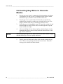
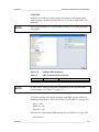
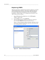
To reassemble the sensor, reverse the earlier work order.
1.
NOTE
Be careful when handling the new ball bearings. Do not drop them or
force them onto the shaft.
2.
CAUTION
4.
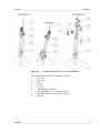
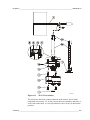
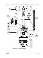
Attach the heating element outlet (5) to the circuit board. Put the
circuit board in place and fasten it with spacers (5).
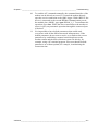
Put the lower body assembly (4) carefully into place. Fasten the
three screws (3) at the bottom of the sensor. Make sure that the
bigger O-ring (14) is correctly positioned between the upper and
the lower sensor bodies. The O-ring is recommended to be replaced
with a new one after each opening. Check also that the connector's
O-ring (14) is properly in its place.
When placing the lower body assembly, make sure that the O-ring is
correctly positioned between the upper and lower bodies. It is
recommended to replace the O-rings with a new ones before
reassembling.
5.
6.
7.
CAUTION
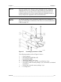
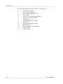
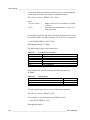
Attach the chopper disc (number 7 in Figure 113 on page 193) back
onto the shaft. The disc has to be positioned so that the disc teeth
do not touch the opto-coupler (6) on the circuit board. Tighten the
screw.
Assure that the chopper disc teeth do not touch the opto-coupler. There
should be 1 to 2 mm space between the bottom of the opto-coupler and
the disc teeth.
3.
NOTE
Take the previous steps in reverse order until assembling the
chopper disc.
Tighten the hex nut of the connector (2).
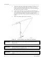
Connect the cable plug to the sensor body connector. Fasten the
sensor body on the cross arm with three screws.
Mount the cup assembly onto the sensor body. Tighten the fixing
screw.
The heating resistance element cannot be removed without special tools.
To avoid any damages, it is recommended that replacement of the
heating element be carried out by the manufacturer.
VAISALA ______________________________________________________________________ 191