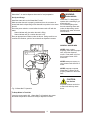
1
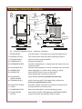
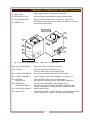
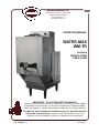
705
WELLS BLOOMFIELD, LLC
10 Sunnen Dr., St. Louis, MO 63143
telephone: 800-807-9054
fax: 314-781-2714
www.wells-mfg.com
OPERATION MANUAL
WATER-MAX
WM-TR
Includes
INSTALLATION
USE & CARE
IMPORTANT: DO NOT DISCARD THIS MANUAL
This manual is considered to be part of the appliance and is to be given to the OWNER
or MANAGER of the restaurant, or to the person responsible for TRAINING OPERATORS of this appliance. Additional manuals are available from your WELLS DEALER.
THIS MANUAL MUST BE READ AND UNDERSTOOD BY ALL PERSONS USING OR
INSTALLING THIS APPLIANCE. Contact your WELLS DEALER if you have any
questions concerning installation, operation or maintenance of this equipment.
p/n 2M-303560 Rev. C
M705 091021
LIMITED WARRANTY STATEMENT
Unless otherwise specified, all commercial cooking equipment manufactured by WELLS MFG. CO. is warranted
against defects in materials and workmanship for a period of
one year from the date of original installation or 18 months
from the date of shipment from our factory, whichever
comes first, and is for the benefit of the original purchaser
only.
THIS WARRANTY IS THE COMPLETE AND ONLY WARRANTY, EXPRESSED OR IMPLIED IN LAW OR IN FACT,
INCLUDING BUT NOT LIMITED TO, WARRANTIES OF
MERCHANTABILITY OR FITNESS FOR ANY PARTICULAR PURPOSE, AND/OR FOR DIRECT, INDIRECT OR
CONSEQUENTIAL DAMAGES IN CONNECTION WITH
WELLS MFG. CO. PRODUCTS. This warranty is void if it
is determined that, upon inspection by an authorized service
agency, the equipment has been modified, misused, misapplied, improperly installed, or damaged in transit or by fire,
flood or act of God. It also does not apply if the serial nameplate has been removed, or if service is performed by unau-
thorized personnel. The prices charged by Wells Mfg. Co.
for its products are based upon the limitations in this warranty. Seller’s obligation under this warranty is limited to the
repair of defects without charge by a Wells Mfg. Co. factory
authorized service agency or one of its sub-service agencies. This service will be provided on customer’s premises
for non-portable models. Portable models (a device with a
cord and plug) must be taken or shipped to the closest authorized service agency, transportation charges prepaid, for
service. In addition to restrictions contained in this warranty,
specific limitations are shown in the Service Policy and Procedure Guide. Wells Mfg. Co. authorized service agencies
are located in principal cities. This warranty is valid in the
United States and Canada and void elsewhere. Please
consult your classified telephone directory, your foodservice
equipment dealer or write the Factory Service Department,
Wells Manufacturing Company, 10 Sunnen Dr, St. Louis,
MO 63143, phone (800) 807-9054, for information and other
details concerning warranty.
SERVICE POLICY AND PROCEDURE GUIDE
ADDITIONAL WARRANTY EXCLUSIONS
1.
2.
3.
4.
5.
6.
Resetting of safety thermostats, circuit breakers, over
load protectors, and/or fuse replacements are not
covered by this warranty unless warranted conditions
are the cause.
All problems due to operation at voltages or phase
other than specified on equipment nameplates are
not covered by this warranty.
Conversion to correct voltage and/or phase must be
the customer’s responsibility.
All problems due to electrical connections not made
in accordance with electrical code requirements
and wiring diagrams supplied with the equipment are
not covered by this warranty.
Replacement of items subject to normal wear, to
include such items as knobs, light bulbs; and, normal
maintenance functions including adjustments of
thermostats, adjustment of micro switches and
replacement of fuses and indicating lights are not
covered by warranty.
Damage to electrical cords and/or plug due to exposure
to excessive heat are not covered by this warranty.
Full use, care, and maintenance instructions supplied
with each machine. Noted maintenance and
preventative maintenance items, such as servicing and
cleaning schedules, are customer responsibility. Those
miscellaneous adjustments noted are customer
responsibility. Proper attention to preventative
maintenance and scheduled maintenance procedures
will prolong the life of the appliance.
7. Travel mileage is limited to sixty (60) miles from an
Authorized Service Agency or one of its sub-service
agencies.
8. All labor shall be performed during regular working
hours. Overtime premium will be charged to the buyer.
9. All genuine Wells replacement parts are warranted for
ninety (90) days from date of purchase on nonwarranty equipment. This parts warranty is limited only
to replacement of the defective part(s). Any use of
non-genuine Wells parts completely voids any
warranty.
10. Installation, labor, and job check-outs are not
considered warranty and are thus not covered by this
warranty.
11. Charges incurred by delays, waiting time or operating
restrictions that hinder the service technician’s ability to
perform service are not covered by warranty. This
includes institutional and correctional facilities.
SHIPPING DAMAGE CLAIM PROCEDURE
NOTE: For your protection, please note that equipment in
this shipment was carefully inspected and packaged by
skilled personnel before leaving the factory. Upon acceptance of this shipment, the transportation company assumes
full responsibility for its safe delivery.
IF SHIPMENT ARRIVES DAMAGED:
1. VISIBLE LOSS OR DAMAGE: Be certain that any
visible loss or damage is noted on the freight bill or
express receipt, and that the note of loss or damage is
signed by the delivery person.
2. FILE CLAIM FOR DAMAGE IMMEDIATELY:
Regardless of the extent of the damage.
3.
CONCEALED LOSS OR DAMAGE: if damage is
unnoticed until the merchandise is unpacked, notify the
transportation company or carrier immediately, and file
“CONCEALED DAMAGE” claim with them. This
should be done within fifteen (15) days from the date
the delivery was made to you. Be sure to retain the
container for inspection.
Wells Manufacturing cannot assume liability for damage or
loss incurred in transit. We will, however, at your request,
supply you with the necessary documents to support your
claim.
xi
TABLE OF CONTENTS
WARRANTY
SPECIFICATIONS
FEATURES & OPERATING CONTROLS
PRECAUTIONS & GENERAL INFORMATION
AGENCY LISTING INFORMATION
INSTALLATION
OPERATION
CLEANING INSTRUCTIONS
DELIMING INSTRUCTIONS
TROUBLESHOOTING SUGGESTIONS
PARTS & SERVICE
CUSTOMER SERVICE DATA
xi
1
2
4
4
5
11
12
13
16
17
17
INTRODUCTION
Thank you for purchasing this Wells Manufacturing Co. appliance.
Proper installation, professional operation and consistent maintenance of this appliance will ensure that it
gives you the very best performance and a long, economical service life.
This manual contains the information needed to properly install this appliance, and to use and care for the
appliance in a manner which will ensure its optimum performance.
SPECIFICATIONS
Electrical:
208 Volts, Single Phase 35 Amps
240 Volts, Single Phase 35 Amps
NOTE: Requires a dedicated 50 Amp circuit
Plumbing:
Water Inlet: 1/4” Male Flare Fitting
Supply: 1/4” Female Flare supplied by a 1/4” O.D. or larger water supply line
NOTE: If water supply run from main supply line to Water-Max™ exceeds 12 feet,
a 3/8” O.D. or larger water supply line is required.
For higher capacity, hook-up to a hot water line.
IMPORTANT: This dispenser must be installed in compliance with all applicable
federal, state and local codes and ordinances.
Dimensions:
Height:
Width:
Depth:
Weight:
28-11/16”
10-1/16” (without tank)
22-7/16” (without tank)
74 lbs. (without tank)
1
15” (with tank installed)
25-1/4” (with tank installed)
150 lbs. (with tank installed and filled)
FEATURES & OPERATING CONTROLS
82
17
73
26
78
79
TANK
(Typical)
13
74
44
42
90
71
45
WATER-MAX™
WATER INLET
FITTING
25
28
29
1
64
Fig. 1 Features & Operating Controls - Water Max™ Dispenser
1. STRAIN RELIEF
(Left Side, Bottom) Field supply wiring enters the appliance here.
13. DELIMING FITTING
Tank mounted quick disconnect fitting for deliming procedure.
17. TANK INDICATOR
Glows when tank is properly installed.
25. POWER SWITCH
Energizes the appliance.
26. DISPENSER NOZZLE
Hot water is dispensed here. Inserting water tank lowers nozzle into
“dispense” position.
28. ADJUSTABLE LEG
Provides required clearance to counter, and allows unit to be leveled.
29. RUBBER FOOT
Allows Water-Max™ to operate without “walking” or sliding.
42. CONNECTOR
Allows WATER TANK to connect to Water-Max™.
Also provides power to keep tank contents hot.
44. CONTROLLER
CIRCUIT BOARD
(Inside left side) Access by qualified technician only.
45. TERMINAL BLOCK
(Inside, under tank shelf) Field supply wiring connects here.
Access by qualified technician only.
64. AIR OUTLET GUARD
Provides a measure of protection for transformer cooling air outlet.
71. FUSES
Provide protection for electrical circuits.
73. POWER INDICATOR
Glows when Water-Max™ is ON and operating normally.
74. TANK POSITION
SWITCH
Held ON when WATER TANK depresses DISPENSER NOZZLE.
Unit will not operate unless WATER TANK is in place.
2
FEATURES & OPERATING CONTROLS (continued)
78. VIEW PORT
Allows digital readout of controller to be observed.
79. DELIMING FITTING
Quick disconnect fitting attaches to deliming solution bottle.
82. STATUS INDICATOR
Glows when filling, flashes when controller is in “error” mode.
90. NAMEPLATE
(Left side) Gives manufacturer information; lists model no., serial no.
and electrical specifications.
TANK ASSY
520
500a
501
509
504
590
507
508
BACK VIEW
FRONT VIEW
Fig. 2 Features & Operating Controls - Water Max™ 5 Gallon Tank
500a. LID HOLDING CLIPS
Ears on LID seat in these clips to secure lid.
501. TANK LID
Hot water is dispensed into the tank here.
Turns clockwise to latch into HOLDING CLIPS.
504. FAUCET PROTECTOR
Provides some protection for FAUCET from damage.
507. FAUCET ASSEMBLY
Controls delivery of hot water to container for food prep, etc.
508. CONTROL
RECEPTACLE
Allows WATER TANK to connect to Water-Max™.
Also provides connection to power to keep tank contents hot.
509. RESERVOIR
CARRYING HANDLE
Used to position the WATER TANK on Mater-Max™
CAUTION - DO NOT ATTEMPT TO MOVE OR CARRY THE
WATER TANK WHEN IT CONTAINS HOT WATER! SEVERE
BURNS MAY RESULT.
520. WATER LEVEL SENSOR
590. NAMEPLATE
Inside WATER TANK. Senses water level. Gives manufacturer information; lists model no., serial no. and electrical specifications.
3
PRECAUTIONS AND GENERAL INFORMATION
WARNING:
Electric
Shock hazard
All servicing requiring
access to non-insulated
electrical components
must be performed by a
factory authorized
technician.
DO NOT open any access
panel which requires the
use of tools. Failure to
follow this warning can
result in severe electrical
shock.
CAUTION:
Risk of
Damage
DO NOT connect or
energize this appliance
until all installation
instructions are read and
followed. Damage to the
appliance will result if
these instructions are not
followed.
Water-Max™ hot water dispenser is intended for use in
commercial establishments only.
This dispenser is designed to dispense hot water used in the
preparation of food for human consumption. No other use is
recommended or authorized by the manufacturer or its agents.
Operators of this appliance must be familiar with the appliance use,
limitations and associated restrictions.
Operating instructions, warnings and labels must be read and
understood by all persons using or installing this appliance.
Cleanliness of this dispenser is essential to good sanitation. Read and
follow all included cleaning instructions and schedules to ensure the
safety of the food product.
Disconnect this appliance from electrical power before performing any
maintenance or servicing.
DO NOT submerge the dispenser or water tank in water. Do not
splash or pour water on, in or over any controls, control panel or wiring.
The technical content of this manual, including any wiring diagrams,
schematics, parts breakdown illustrations and/or adjustment
procedures, is intended for use by qualified technical personnel.
Any procedure which requires the use of tools must be performed by a
qualified technician.
This manual is considered to be a permanent part of the appliance.
This manual and all supplied instructions, diagrams, schematics, parts
breakdown illustrations, notices and labels must remain with the
appliance if it is sold or moved to another location.
This appliance is made in the USA. Unless otherwise noted, this
appliance has American sizes on all hardware.
AGENCY LISTING INFORMATION
This appliance conforms to NSF Standard 4 for sanitation only if
installed in accordance with the supplied Installation Instructions.
U Listed under File E6070.
This appliance is V Listed under File E6070.
This appliance is
E6070
E6070
STD 4
4
INSTALLATION
UNPACKING & INSPECTION
Carefully remove the appliance from the carton. Remove all
protective plastic film, packing materials and accessories from
the
Appliance before connecting electrical power or otherwise
performing any installation procedure.
Carefully read all instructions in this manual and the Installation
Instruction Sheet packed with the appliance before starting any
installation.
Read all instructions in this manual carefully before starting installation of this dispenser. READ AND UNDERSTAND ALL
LABELS AND DIAGRAMS ATTACHED TO THE DISPENSER.
Carefully account for all components and accessories before discarding packing materials.
1 ea.
WATER-MAX™ DISPENSER
1 ea.
AIR OUTLET GUARD
4 ea.
ADJUSTABLE LEGS
1 ea.
WATER TANK ASSEMBLY with LID
1 ea.
DELIMING SOLUTION BOTTLE
1 ea.
LITERATURE PACKAGE
Store these components in a convenient place for later use:
SETUP
Verify that this dispenser installation is in compliance with the
specifications listed in this manual and with local code requirements.
THIS IS THE RESPONSIBILITY OF THE INSTALLER.
Recommended height of the faucet is 38” to 42”. However, the actual
installed height will vary with the requirements of the individual store.
For countertop installation:
The counter at the installation location must be level, provide a
clear space at least 17-1/2”” deep and must be structurally capable
of safely supporting the 150 pound weight of the fully operational
Water-Max™.
Set Water-Max™ on its back. Install the AIR OUTLET GUARD.
Guard is positioned on the bottom of Water-Max™, fully to the rear,
with the open portion toward the front. Install the REAR LEGS to
hold the guard in place.
Install the FRONT LEGS. Make certain all four legs have the
RUBBER FEET installed. Set Water-Max™ upright on the counter.
With the dispenser in its final installed location, adjust for level with
the adjustable legs. With a spirit level, check and adjust the
dispenser for level front-to-rear and side-to-side.
For wall mount installations contact your Authorized Wells Service
Agency:
5
NOTE: DO NOT discard
the carton or other packing
materials until you have
inspected the appliance for
hidden damage and tested it
for proper operation.
Refer to SHIPPING DAMAGE
CLAIM PROCEDURE on the
inside front cover of this
manual.
WARNING:
Risk of
personal injury
Installation procedures must
be performed by a qualified
technician with full knowledge
of all applicable electrical and
plumbing codes. Failure can
result in personal injury and
property damage.
IMPORTANT: A one gallon
pitcher of water will weigh
about 8-1/2 pounds and will be
VERY HOT.
IMPORTANT:
Wall-Mount Installations —
Only factory- produced wall
mounting brackets are
authorized for use with WaterMax™.
Use of any mounting means or
method other than the
factory-produced bracket voids
all warranty on this appliance.
Additionally, owner and/or
installer assume all liability in
connection with injury or
damage resulting from use of
any mounting means or
method other than the
appropriate factory-produced
bracket.
INSTALLATION (continued)
CAUTION:
Risk of Damage
DO NOT connect or energize
this appliance until all Installation
Instructions are read and followed.
Damage to the dispenser will
occur if these instructions are
not followed.
IMPORTANT: Water supply
MUST be a minimum of 1/4”
line, and MUST be capable of
supplying 25 p.s.i. AT ALL
TIMES during the operation of
the dispenser.
IMPORTANT INSTALLATION NOTICE
Installer will be required to test water pressure, water flow, water total
hardness, electrical voltage and amperage; and to record dispenser
installation particulars on the INSTALLATION CHECK OUT form in this
manual.
PLUMBING LINE CONNECTION
If power has been run to the dispenser, verify that the circuit breaker is
turned OFF, and that the power switch is in the OFF [O] position.
Water-Max™ has an internal sensor to verify that there is sufficient
water pressure to operate. Water-Max™ will not operate until a water
supply is connected to the unit or if water pressure is less than 25 p.s.i.
Water-Max™ must be connected to a potable water supply.
NOTICE:
WATER PIPE CONNECTIONS AND FIXTURES DIRECTLY
CONNECTED TO A POTABLE WATER SUPPLY SHALL BE SIZED,
INSTALLED AND MAINTAINED ACCORDING TO FEDERAL, STATE,
AND LOCAL ORDINANCES.
May be connected to either hot or cold water line. Connecting to a hot
water line will increase the volume flow of the dispenser.
Minimum 1/4” copper or flex tubing supply line (3/8” minimum if run
from main supply exceeds 12 feet) with 1/4” female flare fitting.
Minimum 25 psi / maximum 75 psi water pressure at full flow.
The installation of a SHUTOFF VALVE (must be provided by plumbing
installer) on the incoming water line is required. A 1/4 turn ball valve is
recommended to minimize restricting the water flow during operation.
Fig. 3 1/4 Turn Ball Valve
Installation of a PRESSURE REGULATOR and WATER HAMMER
ARRESTOR (to be provided by plumbing installer) on the incoming
water line is recommended.
Clean the incoming waterline: Run water through the line into a sink or
bucket to flush any foreign particles or debris from the waterline.
Assemble incoming water line to the inlet fitting. Turn on water supply
valve and check for leaks.
Test water for pressure at full flow. If a pressure regulator is installed,
adjust pressure to 40 p.s.i. Record this reading on the INSTALLATION
CHECK OUT form.
Test water for total hardness. Record readings on the INSTALLATION
CHECK OUT form.
6
INSTALLATION (continued)
ELECTRICAL INSTALLATION
CAUTION:
NOTICE:
A DEDICATED CIRCUIT OF AT LEAST 50 AMPS IS REQUIRED.
WIRING MUST BE AT LEAST 6 ga., SUITABLE FOR 75º C.
CONDUIT, WIRING AND CONNECTIONS MUST BE INSTALLED
AND MAINTAINED IN COMPLIANCE WITH
FEDERAL, STATE, AND LOCAL ORDINANCES.
Conduit, wiring and connections must comply with the specifications in
this manual, and with local ordinances. A 208V or 240V single phase,
50 amp circuit required.
Field supply wiring must pass thru, and be secured by, the strain relief
on the bottom left side of the dispenser.
Field wiring supply power must connect to the rear-most side of the
terminal block, terminals L1 and L2 as shown.
NOTE: Terminal block is accessible by removing the tank shelf.
Remove the two screws under the shelf and lift the shelf off of the unit.
See wiring tag.
The dis-
penser is
SHOCK HAZARD
Removal of any exterior panel
will result in exposed electrical
circuits. Electrical connection
must be performed by a
qualified technician only.
Use care whenever working
around exposed electrical
circuits.
IMPORTANT:
Contact a licensed electrician
to install and connect
electrical power to the
dispenser.
IMPORTANT:
Damage due to being
connected to the wrong
voltage or phase is NOT
covered by warranty.
IMPORTANT:
Field wiring supply voltage
must correspond to the
position of red wire #11
(i.e. 208V or 240V). Failure to
match wire #11 position to
input voltage can result in
equipment damage or reduced
performance.
Such damage is not covered
by warranty.
Fig. 4 Terminal Block Wiring
CAUTION:
shipped from the factory configured for either 208 volt or 240 volt use.
It may be converted from 208 volt to 240 volt, or from 240 volt to 208
volt, use by moving Wire #11 to either the terminal labeled “208V”, or
to the terminal labeled “240V”, as appropriate for the input voltage.
Optional cord set uses a 4’ cord and NEMA 6-50P plug.
SHOCK HAZARD
Failure to connect the chassis
ground to a suitable earth
ground will result in a potential
shock hazard.
A suitable earth ground must be connected to the ground lug located to
the left of the terminal block.
GROUND
Check all connections to terminal block for tightness.
L1
L2
Test electrical supply for voltage and amp draw while unit is filling water
tank. Record readings on the INSTALLATION CHECKOUT form.
Upon completion of the electrical hook-up and testing, properly reinstall
all panels.
NEMA 6-50P
Fig. 5 NEMA 6-50P Plug
7
INSTALLATION (continued)
CAUTION:
INSTALLATION START-UP AND CHECKOUT
Hot Surface
Exposed surfaces can be hot
to the touch and may cause
burns.
Before turning on power or water to Water-Max™, visually verify:
a. Unit is level, air outlet guard in place, with all legs touching the
counter (countertop installation); or,
Wall brackets securely mounted to wall and unit properly and
securely mounted to brackets (all screws tight) with outlet guard
installed (wall mount installation).
b. All electrical connections properly made and tightened.
Water connections properly made.
Turn on water to Water-Max™. Visually inspect unit for leaks.
Apply power to Water-Max™. Install tank on Water-Max™ shelf (leave
tank lid off at this time). Press power switch to ON and observe
operation:
a. POWER INDICATOR will glow when POWER SWITCH is ON.
TANK INDICATOR will glow when tank is properly installed.
b. After a five second delay, Water-Max™ tank should begin filling.
STATUS INDICATOR will glow steadily while tank is filling,
indicating normal operation.
c.
During initial tank fill, CAREFULLY separate the tank from the
Water-Max™shelf. Verify that water flow stops when the tank
allows the nozzle to rotate up.
d. Reinstall the water tank. Verify that water flow stops when water
reaches the water level probe.
Press power switch to OFF. Discard all water generated thus far by
dispensing containers of water from the faucet until the tank is empty.
Remove the tank from the shelf. Install tank lid on tank.
Press power switch to ON. Reinstall tank on Water-Max™ and allow
tank to fill. Monitor time to fill and record on the INSTALLATION
CHECKOUT form.
Test water temperature at faucet. Water should be at 201ºF.
8
INSTALLATION (continued)
9
INSTALLATION (continued)
CAUTION:
START-UP TROUBLESHOOTING
Hot Surface
Power indicator not lit.
Exposed surfaces can be hot
to the touch and may cause
burns.
a. Verify electrical power is properly hooked-up to Water-Max™ and
circuit breaker is turned ON
b. Verify power switch is turned ON
c.
Verify that water tank is properly in place and mated with the
receptacle
d. Verify water supply is properly installed, is turned on, and is
providing at least 25 p.s.i.
Error indicator flashing. Tank is not filling.
a. Possible cause; sufficient inlet water pressure is not sensed during
tank filling:
Be sure water supply is adequate during all phases of operation.
Other equipment on the water line may be reducing overall water
volume and/or pressure to Water-Max™. Also, be sure any supply
line filters are clean.
b. Possible cause; sufficient temperature rise is not sensed between
inlet and output water while tank is filling:
Be sure electrical supply voltage remains at rated value during all
phases of operation. Otherwise, refer to Water-Max™ Service
Manual p/n 503364.
Water-Max™ will not flow water from the dispense nozzle.
a. Verify that power indicator is lit, and status indicator is not flashing.
Check that tank is properly positioned and that the tank indicator is
lit.
b. Verify that the water tank is in place holding the tank position
momentary switch ON;.
c.
Verify that the water level is below the water level sensor. If water
level is low, verify that the water level sensor and surrounding area
are clean and free from lime and scale.
The water tank heater will not heat:
a. Verify the water tank connector is fully mated with the receptacle.
The tank indicator will glow when the tank is properly installed.
b. Verify power switch is ON.
c.
Check resistance at connector on tank: L1 to L2 = 144Ω (5 gal).
Status Indicator Flashing:
Water-Max™ control board has encountered an error condition. Read
error code through view port. Refer to Water-Max™ Service Manual
p/n 503364 for error code remedial action.
10
OPERATION
Water-Max™ is used to dispense hot water for food preparation.
WARNING:
BURN HAZARD
Set-Up and Usage
Install the water tank on the Water-Max™ shelf.
Make sure that the tank is properly positioned, that the connector is
seated and that the dispensing nozzle lowered into position in the water
tank lid.
Press the power switch to ON and allow the water tank to fill with hot
water.
Status indicator will glow when the tank is filling.
Status indicator will go out when the tank is full.
Water-Max™ is designed to
operate with a matching 5 gal.
water tank only.
Do not hold anything other
than the matching water tank
under the dispensing nozzle.
Splashing hot water will cause
serious burns.
Place an appropriate container under the faucet. Being careful to not
overflow the container, pull the faucet handle to dispense hot water.
GENERAL GUIDELINES
NEVER hold or place
anything, other than the proper
tank, under the dispense
nozzle. Draw water only from
the hot water faucet of the
water tank.
NEVER attempt to remove or
carry a water tank while full of
water.
NEVER attempt to operate
Water-Max™ without the lid
properly installed on the water
tank.
CAUTION:
Hot Surface
Exposed surfaces can be hot
to the touch and may cause
burns.
Fig. 6 Water-Max™ Operation
To Keep Water in Tank Hot
Leave the power switch ON. Water-Max™ will maintain the preset
tank water temperature and will be ready to dispense hot water.
11
CLEANING INSTRUCTIONS
CAUTION:
BURN HAZARD
Water in tank is extremely
hot. Use care when draining
tank.
DAILY CLEANING
PRECAUTIONS:
Press POWER SWITCH to OFF (0).
Drain all water from TANK.
Remove tank from Water-Max™.
FREQUENCY:
Minimum - Daily, or as required
TOOLS:
Soft Cloth, Soft Bristle Brush
CAUTION:
TANK LID
HOT SURFACES
Exposed surfaces can be hot
to the touch and may cause
burns.
CAUTION:
HANDLE &
BONNET
EQUIPMENT
DAMAGE
DO NOT SUBMERGE TANK
IN WATER!
IMPORTANT:
DO NOT use bleach,
abrasive cleansers or
cleansers containing
chlorides.
TANK
FAUCET
FAUCET
BODY
SCREEN
Wipe down the exterior of the Water-Max™ with a soft damp cloth.
Use a soft bristle brush to remove any calcium or lime build-up on the
end of the dispensing nozzle. Wipe dispensing nozzle clean with a soft
damp cloth.
Remove TANK LID.
Wipe TANK FAUCET, interior and exterior of tank with a soft damp
cloth. DO NOT SUBMERGE TANK IN WATER!
Fill tank with cool, clean water. Check operation of faucet.
If the faucet leaks:
Drain tank
Disassemble faucet by unscrewing bonnet from faucet body.
Clean or repair faucet as necessary.
Reassemble bonnet on faucet body.
Reinstall TANK LID.
Drain any remaining water from tank and re-install on Water-Max™.
Press POWER SWITCH to ON (I) and test for proper operation.
Procedure is complete.
12
DELIMING INSTRUCTIONS
PRECAUTIONS: Water in tank is EXTREMELY HOT (± 200ºF)
Turn Water-Max™ OFF and allow to cool
Tank full of water is HEAVY (64 lbs.)
Drain water from tank before moving.
FREQUENCY:
TOOLS:
CAUTION
Burn Hazard
Water in Water-Max™ is
EXTREMELY HOT
Weekly, or as required when Water-Max™ will not
maintain water at 197ºF or higher.
Goggles, Chemical Resistant Gloves
LIMESHIELD™ Scale and Food Soil Inhibitor
Solution Bottle
Scrub Pad (Standard Green)
CAUTION
Chemical Burn
Hazard
Deliming chemicals are
caustic.
Wear protective goggles and
gloves during this procedure.
1. Power switch is located on right side of Water-Max™ base.
ON
Press POWER SWITCH to OFF.
Drain 1 GALLON of water from TANK.
OFF
1
GAL
2. Examine SOLUTION BOTTLE for serviceability. If it is cracked or
distorted, replace it with a new bottle.
HOT
Pour 2.5 ounces of LIMESHIELD™ into solution bottle.
Slowly add 4 ounces of warm tap water.
DISPENSER CAP is attached to the top of Water-Max™ with a
chain. Screw quick-disconnect dispenser cap onto solution bottle.
Gently shake solution bottle. Allow solution to completely
dissolve.
IMPORTANT: Delime with LIMESHIELD™ Scale and Food Soil
Inhibitor ONLY!
INSTALL QUICKDISCONNECT
3. QUICK-DISCONNECT FITTING is located on the left top of WaterMax™.
Invert solution bottle. Insert bottle quick-disconnect fitting into
Water-Max™ quick- disconnect fitting. Press solution bottle down
until fitting “clicks”, locking solution bottle in place.
INSERT
BOTTLE
13
DELIMING INSTRUCTIONS (continued)
WAIT
4. Squeeze solution bottle and force deliming solution into
Water-Max™
Allow Water-Max to set for 10 MINUTES with solution bottle in
place.
10 MIN
SQUEEZE
5. Press BUTTON on quick-disconnect fitting to release solution
bottle. While pressing button, lift solution bottle straight up.
Unscrew dispenser cap from solution bottle.
Rinse solution bottle and retain for next deliming cycle.
REMOVE BOTTLE
ON
WAIT
6. Press power switch to ON. Water-Max™ will dispense water
and deliming solution into tank.
OFF
ON
1 HOUR
OFF
When Water-Max™ stops dispensing, press power switch to
OFF. Allow Water-Max™ to set for I HOUR with deliming
solution in tank.
After I hour, drain pitchers of water from tank until tank is
empty.
UNTIL
TANK
IS
EMPTY
Pour all water and solution from tank into a sink or appropriate
container for disposal.
7. Remove tank from Water-Max™
Remove TANK COVER from tank. Rinse cover and dry. Store
tank cover for later use.
REMOVE TANK
REMOVE LID
14
DELIMING INSTRUCTIONS (continued)
8. WATER LEVEL PROBE is located in the tank, in the back right corner near the top.
SCRUB TANK
Using a STANDARD GREEN SCRUB PAD, clean all scale and
lime from the water level probe.
Using the scrub pad, clean all scale and lime deposits from the lip
of the tank opening and from the inside of the tank.
INSIDE TANK,
AROUND LIP,
PROBE
9. Rinse tank thoroughly at least twice.
Pour all rinse water into a sink or appropriate container for
disposal.
RINSE
TWICE
10. Reinstall tank cover on tank.
Reinstall tank on Water-Max™. Make sure tank connector is
fully seated on shelf.
Press power switch to ON.
After a short delay, tank will begin filling.
ON
OFF
REINSTALL
LID & TANK
Procedure is complete
15
TROUBLESHOOTING SUGGESTIONS
SYMPTOM
POSSIBLE CAUSE
SUGGESTED REMEDY
POWER INDICATOR not lit
Water-Max™ not connected to power
Check circuit breaker
POWER switch OFF
Press POWER switch to ON
Insufficient water supply
Check water supply turned ON
And supplying at least 25 p.s.i.
Water tank not installed
Check tank for proper installation
TANK INDICATOR not lit
Tank not properly seated in receptacle
Check tank for proper installation
STATUS INDICATOR
flashing
ERROR detected - water pressure
insufficient
Check water supply turned ON
And supplying at least 25 p.s.i.
ERROR detected - temperature rise
between inlet and outlet insufficient
Be sure voltage is maintained
during all phases of operation
RESET Water-Max™: Turn POWER SWITCH OFF. Wait 20 seconds.
Turn POWER SWITCH ON. If unit resets and status indicator comes
on without flashing, error was (probably) a low water condition. Otherwise, contact your Authorized Wells Service Agency.
Tank is full
Normal operation
Tank is sensed as full, but is actually
low
Clean water level probe
Tank not properly installed
Check tank for proper installation
INDUCTIVE HEATER
operates intermittently
Internal hi-limit tripping (cooling fan
dirty or obstructed)
Be sure all cooling openings
and louvers are unobstructed.
Otherwise contact Authorized
Wells Service Agency
WATER TANK will not heat
Tank not properly installed (TANK
INDICATOR not lit)
Check tank for proper installation
Internal damage
Contact Authorized Wells
Service Agency
No water flow from
dispense nozzle (power
indicator lit, status indicator
not flashing)
OPERATIONAL NOTES
Water-Max™ will not operate if water pressure is less than 25 p.s.i. If Water-Max™ shuts down (status
light flashes) for no apparent reason, other equipment on the water line may be robbing water pressure
and/or volume from Water-Max™.
ERROR CODES are displayed on the control board readout, visible through the view port on the upper
right side of the dispenser. Refer to Water-Max™ Service Manual p/n 503364 for error code meanings
and suggested remedies.
There are no user serviceable components in the appliance. In all cases of damage or component
malfunction, contact your Authorized Wells Service Agency for repairs.
16
PARTS & SERVICE
DESCRIPTION
SERVICE
PART NO.
TANK, 5 GALLON, MODEL DT-5
22658
PITCHER, PLASTIC, 4 QT.
84501
ASSEMBLY (STRAINER / PRESSURE
REGULATOR WITH GAUGE /
WATER HAMMER ARRESTOR)
84868
CORD SET #6AWG/3W/NEMA 6-50P
84897
PRESSURE REGULATOR (ONLY)
8541-401
PRESSURE GAUGE (ONLY)
8541-402
WATER HAMMER ARRESTOR (ONLY)
9012-54
WATERLINE “Y” STRAINER (ONLY)
SA 9052
IMPORTANT: Use only
factory authorized service
parts and replacement
filters.
For factory authorized
service, or to order factory
authorized replacement
parts, contact your Wells
authorized service agency,
or call:
Wells Manufacturing Co.
10 Sunnen Dr
St. Louis, MO 63143
phone:(800) 807-9054
Fax: (314) 781-2714
(Service Parts Dept.)
Service Parts Department
can supply you with the
name and telephone
number of the WELLS
AUTHORIZED SERVICE
AGENCY nearest you.
CUSTOMER SERVICE DATA
please have this information available if calling for service
RESTAURANT _____________________________ LOCATION _____________
INSTALLATION DATE ________________________ TECHNICIAN ___________
SERVICE COMPANY ________________________________________________
ADDRESS ___________________________ STATE ______ ZIP__________
TELEPHONE NUMBER (_____)_____-_________
EQUIPMENT MODEL NO. _______________
EQUIPMENT SERIAL NO. _______________
VOLTAGE: (check one)
208
240
17
WELLS BLOOMFIELD, LLC
10 Sunnen Dr., St. Louis, MO 63143
telephone: 800-807-9054
fax: 314-781-2714
www.wells-mfg.com