1
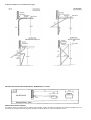
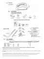
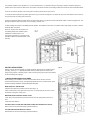
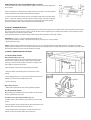
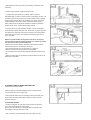
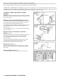
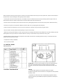
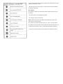
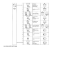
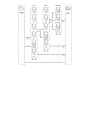
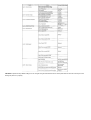
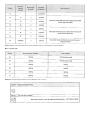
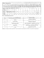
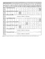
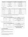
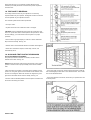
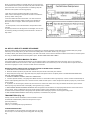
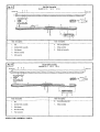
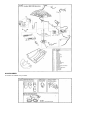
Search HOME BOSS BRD1A BOSS BRD9 BOSS BOL4 BOSS BOL6 MARANTEC COMFORT 800 /1000 BOSS BS1 MORE... Comfort 800 /1000 Sectional Garage Door Opener Installation Manual Important Safety Information This manual is essential to the safe and proper installation, operation, and maintenance of your operator. Read and follow all guidelines and operating instructions before the-first use of this product. Operate the garage door operator at 240V, 50Hz to avoid operator damage. Garage doors are heavy, moving objects. When coupled with an automatic operator, electrical power is also present. If not properly installed, balanced, operated, and maintained, an automatic door can become dangerous and cause serious injury or death, Please pay close attention to the WARNING and CAUTION notices that appear throughout this manual. Failure to follow certain instructions may result in damage to the door or door opener, or may result in severe injury or death to yourself or others. Tools The instructions will refer to the tools shown below for proper installation, adjustment, and maintenance of the garage door operator. Additional tools may be required depending on your particular installation. WARNING: A garage door is a heavy moving abject and can cause serious injury or death. An unbalanced door might not reverse when required, and can increase the risk of injury. If your garage door is out of balance, or if it binds or sticks, call for professional garage door service. Garage doors, springs, pulleys, cables, and hardware are under extreme tension and can cause serious injury or death. Do not try to adjust them yourself. Ropes left on a garage door could cause someone to become entangled and could kill them. Remove all ropes connected to the door before installing your operator. Take a moment to survey your garage and garage door. - Is there an access door besides the garage door? If not, you should install an emergency key release kit. - With the garage door closed, check alignment of door and garage floor. The gap, if any, should be no more than 6mm. If the gap is larger than this, repair floor or door before installing operator. - The operator is intended for installation on a properly balanced and adjusted garage door. DO NOT INSTALL IF DOOR IS UNBALANCED OR BROKEN. - Check balance of door in mid travel and during full range of opening and closing. Lift the door about half way, as shown in Fig. 2 & 3. Release the door. It should remain in place, supported by its springs. Raise and lower the door fully to check for binding or sticking. - If door is out of balance or needs repair, DO NOT ADJUSTS IT YOURSELF. CALL A QUALIFIED GARAGE DOOR SERVICE PROFESSIONAL to adjust your door. - If your door is over 2.1m high, you will need a longer rail. Check the type of door construction you have. The information contained in the figures below will be referred to later in the manual for proper installation on the different door types. GARAGE DOOR OPERATOR SYSTEM OVERALL DIMENSIONS (2.1m DOOR) OPERATOR PACKAGE CONTENTS The following items are included with your Garage Door Operator (GDO). All hardware components are located in the GDO carton. The accessories are packaged with their respective hardware in separate packs for ease of identification and use. WARNING: IMPORTANT INSTALLATION INSTRUCTIONS TO REDUCE THE RISK OF SEVERE INJURY OR DEATH: 1. READ AND FOLLOW ALL INSTALLATION INSTRUCTIONS. 2. Check with the door manufacturer to determine if additional reinforcement is required to support the door prior to installation of the garage door operator. 3. Install garage door operator only on a properly balanced garage door. An improperly balanced door could cause serious injury. Have a qualified service person make repairs to garage door cables, spring assemblies, and other hardware before installing the opener. 4. Remove all ropes and disable all locks connected to the garage door before installing operator. 5. If possible, install the door operator 2.1m or more above the floor. For products having an emergency release, adjust the emergency release cord for the knob to be within reach, but at least 1.8m above the floor and avoiding contact with vehicles to avoid accidental release. 6. Do not connect the operator to source of power until this manual instructs you to do so. 7. Locate the wall control panel: (a) within sight of door, (b) at a minimum height of 1.5m above the ground so small children cannot reach it, and (c) away from all moving parts of the door. 8. Place the Operating Warning Label next to the wall control panel in a prominent location. Affix Safety Label on inside of garage door. The Emergency Release Tag must remain on the emergency release cord. 9. After installing the operator, test Safety Reversal System. Door MUST reverse when it contacts a 40mm high object (or 50mm x 1OOmm board laid flat) on the floor. Shown on the right is an overall view of a completed garage door operator system installed on a sectional door. The arrangement is similar for a one-piece door (except for differences described later in this manual). INSTALLATION STEPS Identify a sound structural support on header wall above garage door for header bracket mounting_ See Fig. 11. If appropriate header does not exist, replace or install a new support using a 50mm x 100mm board. Fasten it securely using lag screws (not provided) to structural supports of garage. 1. MEASURE AND MARK DOOR AREA. Before starting your installation, the door and the header above the door must be measured and marked. This way, the appropriate brackets can be mounted at the correct locations avoiding installation and operating difficulties later. MARK VERTICAL CENTER LINE: -Measure door width, then locate the center point (Fig.1 0). -Mark a vertical line on the upper half of your door, on the top edge of your door, and on the header, through the center point. MEASURE DOOR'S HIGHEST TRAVEL POINT: -Open door to its highest travel point and measure from the garage floor to the top of door. -Write down this distance. FOR SECTIONAL DOORS AND ONE-PIECE DOORS WITH HORIZONTAL TRACK: Add 31.75mm to the door travel height (measured above). FOR ONE-PIECE DOORS WITHOUT TRACK: Add 95.25mm to the door travel height (measured above). MARK HORIZONTAL LINE FOR HEADER BRACKET LOCATION: -Close door and measure the required distance (determined above) from the garage floor to the header. -Mark a horizontal line, intersecting the vertical center line, on header. This is the position at which the bottom of the header bracket should be installed. -In case of minimal clearance above the door, the header bracket may be mounted to the ceiling. In this case, extend the vertical center line onto the ceiling, and mark a horizontal line on the ceiling no further than 1 01.6mm from the header wall. The header bracket should be mounted no farther than this distance from the header wall. 2. INSTALL HEADER BRACKET WARNING: If the header bracket is not rigidly fastened to a sound structural support on the header wall or ceiling, the safety reverse system may not work and could cause serious injury or death. DO NOT move or adjust springs or garage door hardware, as these parts are under extreme tension and could cause injury or death. - Mark pilot holes location on header through header bracket holes where lag screws will be inserted. IMPORTANT: See Fig. 11 for which header bracket holes to use. - Drill 3/16" pilot holes into header, and install bracket with lag screws (5116 x 1-3/4") provided. - Tighten lag screws firmly. NOTE: Follow the same procedure if header (shown in Fig. 11) runs vertically instead of horizontally and is the only option for mounting header bracket to header wall. In case of minimal clearance above the garage door, the header bracket may be mounted to the ceiling. Follow the same steps above to ensure a sound surface for mounting. 3. INSTALL DOOR BRACKET TO DOOR A. FOR SECTIONAL DOORS: Wood Sectional Doors (Fig. 14) - Position door bracket (Fig. 13) along vertical center line of door with pin hole facing top of the door and top edge of the bracket 101.6mm to 127mm below top edge of the door, or roughly at the same height as top rollers on the door. - Mark locations of securement holes through door bracket. - Drill two 6.35mm holes through door for securement of door bracket. - Insert carriage bolts (1/4” x 2") from the outside through door and bracket, then secure with lock washers and nuts - Tighten nuts firmly. Metal Sectional Doors - Attach door bracket with two teck screws (provided) per Door B. FOR ONE-PIECE DOORS: Before starting the installation of the door bracket, cut off mounting leg from opposite side of pin hole. One-Piece Doors with Exposed Frames (Fig. 15) - Position center of door bracket on the center line on the top edge of door. - Mark the position where carriage bolts will go through bracket, and drill two 6.35mm holes through top frame of door. - Install carriage bolts from the bottom, through door frame and bracket, and secure with lock washer and nut from top. - Tighten nuts firmly. One-Piece Doors without Exposed Frames (Fig. 16) - For doors without exposed frames, use alternate method of mounting door bracket. - Mark and drill two 3/16" pilot holes into top of frame, then secure bracket with 5/16" x 1-5/8" lag screws (not provided). 4. ATTACH RAIL TO OPERATOR HEAD WARNING: When fastening the rail to the operator, use only the screws provided. Use of any other screws may result in operator falling from ceiling and causing damage to persons or property in the garage. NOTE: Rail comes fully preassembled with straight already attached. - Unpack one-piece preassembled rail. - Leave straight door arm taped inside rail for safe and convenient installation-it will be untaped and used later. - Position operator with control panel facing front of garage. Rest operator head on cardboard or protective surface on floor so opener does not get scratched. Chassis side of opener (with motor shaft sticking out) facing up. - Position rail onto operator chassis by lining up rail sprocket opening with motor head shaft (Fig. 17A). Make sure shaft engages teeth inside rail sprocket. Press rail down firmly onto shaft and opener chassis. DO NOT HAMMER. - Position 2 "C" rail clips over rail and onto chassis. Flanges on "C" rail clips MUST fit into guide posts recesses (Fig. 17B). - Insert screws (6 x 14) through bracket holes and into chassis holes, and tighten screws firmly to hold rail to head (Fig. 17C). - For sectional doors, proceed to step 8-5. ADDITIONAL STEP FOR ONE-PIECE DOORS ONLY: IMPORTANT NOTE: For installation on One-Piece Doors only, the straight door arm that is factory installed onto the rail must be replaced by the curved door arm supplied as part of hardware in powerhead box. This must be done after attaching rail to powerhead, before moving .to step 8- 5. - Turn rail and operator over so that open channel in rail faces up. - Untape straight door arm that is secured inside rail. - Remove and save the two phillips head screws that are securing the door arm pin and straight door arm (Fig. 18). - Lift arm and pin straight out of slot in trolley, and remove pin from straight door arm. - Insert pin into short side of curved door arm as shown. Ill Orient arm so that long side extends away from trolley. - Carefully insert pin and door arm into slot in trolley. Push pin into slot with door arm so pin is fully seated into trolley slot. IMPORTANT: Pin must be straight and seated properly - Secure pin and curved arm with the two phillips screws which were removed from trolley-DO NOT use any other screws. Tighten screws firmly. - Turn rail and powerhead over so that open channel in rail faces down. Now proceed to Step 8-5. 5. ATTACH RAIL TO HEADER BRACKET - Support operator head slightly off the floor. - Lift the opposite end of the rail up to the header bracket. - Position rail end-stop within the openings in the header bracket. Insert pins into header bracket holes. Secure rail with the nut. (See Fig. 19A) 6. POSITION OPERATOR FOR MOUNTING Once rail is attached to header bracket, support operator on ladder, or use the assistance of another person to support operator high enough so door can open without hitting the rail. A. SECTIONAL DOORS AND ONE-PIECE DOORS WITH TRACK: - Open garage door to fully opened position, and place a 50mm x 100mm board laid flat between the door and the rail. See Fig.20. This provides an easy method of ensuring the correct Fig. 21 mounting height of the opener. B. ONE-PIECE DOORS WITHOUT TRACK: - Disconnect trolley by pulling down on emergency release knob. Move trolley toward opener head. - Open door all the way so that it is parallel to the floor, or slightly tilted toward the front of the garage. DOOR SHOULD NOT BE TILTED TOWARD THE BACK OF GARAGE. - Position operator so that top of operator head is level with top of opened door. - To check for correct mounting height, temporarily position curved door arm as if connecting to door bracket. See Fig. 21. The long side of the arm should be parallel to the floor when door is fully opened. Raise or lower powerhead so that arm will be parallel to floor. - Temporarily support head at this height, and prepare to mount the operator to ceiling. 7. MOUNT OPERATOR TO CEILING WARNING: If not properly secured, the operator could fall and injure someone. Secure opener to structural supports or framing. Do not mount to drywall, plaster, or other such material. - Position operator head so that rail is lined up with ceriter line of open door. - Line up hanger brackets (not provided) with ceiling joists or framing to locate where brackets are to be fastened. See fig. 22. - Mark location for 5/16" lag screws (not provided), and drill two 3/16" pilot holes. - Fasten hanger brackets to joists using lag screws. - If garage framing supports are not visible, attach a length of, perforated angle or a 50mm x 100mm board to the ceiling, securing it to the hidden joists with lag screws long enough to fasten firmly to garage framing (extra hardware items not provided). Then, attach one end of hanger brackets to the angle or 50mm x 100mm board mounted to ceiling. Attach other end of hanger brackets to operator's perforated angles. See fig. 23 for an alternate mounting methods. - Once operator is securely fastened in position, remove wood blocks and temporary supports and lower door. Check door for proper operation and clearance by manually moving door to full open and closed position. If door hits rail at any point, raise operator head slightly higher and re- mount in position. NOTE: To provide additional support for 2.4m doors and higher, use the optional support bracket and place it on 1/3rd of the overall rail span from the door header bracket end. - Measure the rail's overall span. Bracket is located at the end of the overall rail span close to the operator. See fig. 24. - Place support bracket over rail (close side) on a diagonal. - Make sure support securement clamps clear rail sides. - Secure bracket onto rail by twisting support bracket as indicated in fig. 24A. - Attach mounting strap (not provided) to support bracket and secure by fastening it to the ceiling. 8. CONNECT ARM TO DOOR AND TROLLEY - Make sure door is fully closed -Remove tape from rail holding straight door arm (sectional door only) and allow door arm to hang freely. -Pull the manual release cord on the trolley to disconnect trolley from chain or belt connector. Slide trolley to position it about 1 01.6mm away from the door. A. SECTIONAL DOORS: - Position curved door arm into door bracket channel so that short end of arm will be attached to door bracket. See Fig. 25A. Curved door arm should be attached roughly at the same height as the top rollers of the door. - Align curved door arm and bracket holes, then insert clevis pin through holes. Attach cotter ring to hold pin in place. - Position straight arm and curved arm to form an angle with the door (Fig. 25) and at least two sets of holes line up. Select two overlapping holes as far apart as possible and secure arms together with hex bolts (5/16-18) and lock nuts. B. ALL ONE-PIECE DOORS: - Curved door arm should already be attached to trolley in place of straight door arm. See Fig. 18. - Position free end of curved arm into door bracket slot. Align curved door arm and bracket holes, then insert clevis pin (5/16"dia.) through holes. Attach cotter ring to pin to hold in place. See Fig. 26. C. SECTIONAL AND ONE-PIECE DOORS: - After connecting appropriate door arm, ensure trolley is disengaged. Check for proper door operation by manually lifting then lowering to fully opened and closed positions. - Readjust door arm if needed. PULL DOWN ON RELEASE KNOB TO LOCK TROLLEY, THEN MOVE DOOR MANUALLY UNTIL TROLLEY LOCKS WITH CHAIN OR BELT CONNECTOR. 9. CHECK EMERGENCY RELEASE WARNING: To prevent possible SERIOUS INJURY or DEATH from a falling garage door: - If possible, use emergency release knob to disengage trolley ONLY when garage door is CLOSED. Weak or broken springs or unbalanced door could result in an open door falling rapidly and/or unexpectedly. - NEVER use emergency release knob unless garage doorway is clear of persons and obstructions. - NEVER use knob to pull door open or closed. The emergency release cord with red knob, which is already attached to the trolley, is extremely important parts of the operator system Fig. 27. Pulling the release cord (1) disengages the door from the opener. This allows the door to be moved manually up and down independent of the opener motor. If the door is in the open position, use extreme care when using the release. Use emergency release to disconnect the door if the power is out. It should also be used if for some unforeseen reason, the door strikes a person or object during its travel and does not automatically reverse off the obstruction. To release door - pull firmly down on red knob. (Fig. 27) Prior to re-engaging door, ensure that all obstructions are removed and door is operating properly manually. Before re-engaging trolley with a chain or belt connector, pull down on green handle (2). Now the door can be reconnected by moving it manually and bringing it into position when the connector is inside of the trolley. 10. INSTALL PHOTO EYE SAFETY SYSTEM (optional) CAUTION: To provide the maximum amount of protection, the photo eye sensors must be mounted between 88.9mm and 127mm above the floor. See Fig. 28. MOUNTING THE PHOTO EVE SENSOR BRACKETS TO WALL: -Locate the mounting position for brackets (bracket can be mounted in any position as long as photo eye beam will have a clear path from one side of door to other side after mounting). -Use the bracket mounting holes as a template to locate and drill (2) 3/16” diameter pilot holes on both sides of the garage door as shown in Fig. 28. -Secure the bracket with 1/4” x 1-1/2” lag screws provided as shown in Fig. 28. Fig. 28A MOUNTING THE PHOTO EVE SENSORS TO MOUNTING BRACKET. Fig. 28A -Install the sensors to the mounting bracket by inserting bend clips of sensor bracket through the vertical slot on mounting bracket. -Insert straight dips through other set of vertical slot on the mounting bracket. -Twist one of the straight clips slightly to lock the sensor in place once inserted through vertical slot on the mounting bracket. -Repeat the above procedure for the other sensor. SENSOR PROTECTION Fig. 29 -Before performing maintenance work in garage, such as, power washing, painting, and other tasks;; protect sensors with provided sensor caps. DUAL DOOR INSTALLATION Fig. 30 -In dual door installations, the transmitter (TX) and the receiver 11. CONNECTING WIRES TO OPERATORS Reference: When installing external control elements, or safety and signal equipment, the relevant instructions must be observed. Advice: If a photocell is to be connected, it must be installed before the express programming procedure is carried out. The photocell will Advice: Before connecting a control element to the terminals with system sockets, the corresponding shorting plug must first be only be recognised automatically by the controls if this is the case. Otherwise the photocell must be programmed after installation. removed. 12. INSTALL LIGHT BULBS AND LENSES CAUTION: To prevent possible OVERHEATING of the end panel or light socket;; -Use ONLY E14 size standard neck incandescent light bulb(s). -DO NOT use short neck or specialty light bulbs. -DO NOT use halogen light bulbs. -DO NOT use a bulb with a rating higher than 40 Watts (W). A stronger or larger bulb may result in fire or damage to the opener. To prevent possible radio frequency (RF) signal interference DO NOT use compact fluorescent lamp (CFL). -Install a maximum 40W standard neck E14 size incandescent bulb (not provided) into lamp socket(s). -Line up lamp lens tabs with corresponding slots in chassis. Snap lens onto chassis. -To remove lamp lens, pull lamp lens to unsnap from housing and chassis. 13. CONNECT TO POWER To reduce the risk of electric shock, your opener is provided with an insulated power cord with a 3-prong plug. The cord must be connected to a standard outlet. If there is no outlet available at the location, you must have a qualified electrician install an approved outlet in this area. WARNING: To prevent electrocution of fire, installation and wiring must be done in accordance with local electrical and building codes. DO NOT use an extension cord. - Plug the operator into an outlet (Fig. 34). - An indicator lights (LED's #4 and #8) on the operator control panel will turn on showing that the power is "On" and the opener is ready to set the adjustments. - DO NOT operate or run the opener at this time. PERMANENT WIRING CONNECTION: (If required by your local electrical code) If local codes require your operator to be connected via permanent wiring instead of a cord and plug, your operator must be converted, as shown in Fig. 35. Contact a qualified electrician to run the necessary wiring to your operator and to perform the electrical connections. WARNING: To prevent electrocution, disconnect the operator from power and turn off power at circuit breaker for the circuit you will be using to connect to the opener. Remove operator housing by removing the four screws, two screws located at the front by the control panel area, and two screws located on the back of the unit, then pulling the housing away from the chassis. - Cut the power cord close to strain relief cover, so that after cut, there is at least 152.4rnm of wiring remaining. Remove approx. 38mm of black insulation left on the cable to expose the two conductor leads (white-neutral and black-hot). - Remove screw and unsnap the power cord strain relief cover by disengaging the tabs, and remove this part (save for reattachment later). - Remove the cut power cord and discard. Replace the strain relief cover by snapping tabs back into place. - Using a hammer and screwdriver or punch, knock out conduit hole, and bring in the permanent wiring and conduit. - Secure conduit to chassis (method varies depending on type of conduit used). - Attach the incoming power leads (hot, neutral, and ground) to the remaining internal wires using suitable wire nuts (not provided). Tight wire leads together with a nylon cable tie to avoid the leads from coming in contact with the relay circuit board, see Fig. 35A. - Reinstall operator housing and secure housing with screws. Make sure that when reinstalling operator housing, no wires will be pinched between the housing and the chassis. - Complete the remaining installation. - Turn on power at breaker. 14. CONTROL PANEL Operating Elements ATTENTION: To ensure correct operation, the path of the photocell beam must not be interrupted during the express programming procedure. Exception: The door leaf in conjunction with a photocell in the door frame area. 15. INITIAL SYSTEM SETUP ADVICE: - For proper initial operation of the operator system, the express programming procedure must be carried out. This applies for initial operation and after a reset. - A photocell in the door frame area is automatically programmed during express programming. No additional programming steps are necessary for this purpose. - A door frame position that has been programmed for a photocell can only be deleted by resetting the control. - After altering the door frame position, a reset must be carried out followed by express programming. Preconditions The following conditions must be assured before express programming can commence: - The door must be in the CLOSED end position. - The carriage must be connected up. Advice: When programming the OPEN and CLOSED door positions, the reference point must be passed. The controls are programmed using the plus (+), minus (-) and (P) buttons. If no buttons are pressed within 120 seconds while in programming mode, the controls revert to operating mode. A corresponding message is displayed. - Carry out the express programming according to the following procedure. 16. ADVANCED SETTINGS CAUTION! Important factory default settings can be changed using the extended functions. All the parameters must be set correctly to avoid damage to persons or property. Attention! After a reset all the parameters revert to the factory settings. In order to ensure that the controls operate properly: -all the required functions must be re-programmed, -the remote control unit must be re-programmed, -the drive system must be driven once to the OPEN and CLOSED door position. Advice: -Only the intermediate position that was programmed last can be used. -If an automatic closing timer is activated (Level 3/ Menu 1), the relay output (Level 1 / Menu 7) cannot be programmed. Reference: If change are made in Menus 3 and 4 in Level 1, a new performance check must be carried out (Section 8-16) Menu 7: Relay Output Menu 8: Reset * All connected and operational safety devices are recognized automatically after resetting. * The higher the setting, the higher the driving power. ** The lower the setting, the more sensitive the automatic cut-out. Caution! After switching off or increasing the automatic cut-out increments (Menu 3 and 4): To exclude any risk of injury, the tests specified in EN 12453 and EN 12445 for validating the correct limitation of force must be performed. Menu 1: Automatic Closing Timer Advice: Without a connected photocell or closing prevention device, only parameter A1 can be adjusted. Menu 7: Signal Light Reference: The signal light connection can be adjusted in level 1, menu 7. Menu 1: Programmable Impulse Input Reference: The lighting duration programmed is only active when the relay output (Level 1 / Menu 7) is programmed for lighting (H7). Reference: If changes are made in Menu 1,2,3,4,6 and 8 in Level 6, a new performance check must be carried out (Section 8-16). Attention! If a photocell is connected, it is automatically recognised by the controls after MAINS ON. The photocell can be reprogrammed later. Menu 1: Photocell Menu 3: Function of Automatic Cut-Out Menu 4: Operating Modes 1. Door revers a little: The drive system moves the door a short distance in the opposite direction in order to free an obstacle 2. Door reverses completely: The drive system moves the door to the opposite end position. Menu 5: Function of the direction command transmitter Menu 6: Function of the impulse command transmitter 17. TEST DRIVING POWER Check: After express programming and after making changes to the programming menu, the following learning runs and checks must be carried out. The operator system determines the maximum required driving power during the first two runs after setting the end positions of the door. - Operate the operator system (with the door coupled) to drive the door once from the CLOSED position to the OPEN position and back to the CLOSED position without interruption. During this learning run, the operator system determines the maximum push and pull forces and the reserve power required to move the door. 18. TEST SAFETY REVERSAL The safety reversal function of your operator is an extremely important feature of your operator. Testing this function ensures the correct operation of your operator and door. The reversal system test should be performed: - Once per month. - Anytime the travel or force limits are reset or changed. CAUTION! Once the adjustments have been set and the door has been run up and down twice uninterrupted for the operator to "learn" the new settings, you must test the reversal system for proper operation. - Place a 38mm high rigid object (or a 50mm x 100mm board laid flat) on the floor directly. See Fig. 38. - Start the door in the downward direction and watch what happens. - When door contacts the object, it should stop, reverse, and automatically return. 19. ALIGN AND TEST PHOTO EYE SENSORS PHOTO EVE SENSORS ALIGNMENT: The photo eye sensors maintain an invisible, unbroken beam between each other. See Fig. 40. NOTE: Sensor alignment must be done with the door in the closed position in order to ensure proper visibility of the sensor indicator LED. -When the photo eye system is connected to the operator and the power is on, the green light on the transmitter sensor flashes, if the sensors are not aligned. When the sensors are aligned, the green - If the door does not reverse, reset the down travel limit so that the door travels slightly further down in the closed direction. Then, retest the unit as described above. light on the transmitter sensor will turn steady. See Fig. 40. -Sensors must be installed parallel to the door plane and make sure the sensors are facing each other. SAFETY TEST: - If the door still does not reverse, disconnect your operator and call a service person. Photo eye sensors installed on opposite sides of your door opening are intended to detect a person or object in the path of the door and prevent the door from moving downward. The following steps will determine if the system is functioning properly: -Open door using the operator's transmitter or wall control. -Place a box or other object in the path of the door so it breaks the photo eye beam. See fig. 40A. -Press and release the wall control button. The door should not move in the down direction. LED# 7 and #8 on the operator will flash. If this does not happen, disconnect operator and call for service. - To reset operator, remove the obstruction and operate the door normally. -If photo eye sensors are not aligned or are damaged, door can only be closed by pressing and holding wall control button until door is fully closed. 20. APPLY LABELS TO INSIDE OF GARAGE Several important safety and instruction labels are included with your operator package. These labels must be posted inside your garage where they can be easily seen by all. We recommend installing them in the location shown in fig. 9 on page 7. To affix the labels, peel off the protective backing, and stick onto smooth, clean surface. If labels don't adhere well to surface, use tacks (wood door only) or additional adhesive to securely affix in place. DO NOT PAINT OVER ANY LABELS. 21. ATTACH OWNER’S MANUAL TO WALL It is important that the manual be stored where it can be referred to later in case adjustments need to be made, and I or new controls or accessories added. Store the manual in a safe, easily accessible location. We recommend you use an envelope with an eyelet to store the manual in the garage on a nail or hook on the wall near the wall control. IMPORTANT SAFETY INSTRUCTIONS TO REDUCE THE RISK OF SEVERE INJURY OR DEATH: 1. READ AND FOLLOW All INSTRUCTIONS CAREFULLY. 2. Never let children operate or play with door controls. Keep the remote control away from children. 3. Always keep the moving door in sight and away from people and objects until it is completely closed. NO ONE SHOULD CROSS THE PATH OF THE MOVING DOOR. 4. NEVER GO UNDER A STOPPED, PARTIALLY OPEN DOOR. 5. Test door operator monthly. The garage door MUST reverse on contact with a 38mm high object (or a 50mm x 100mm board laid flat) on the floor. After adjusting either the force or the limit of travel, retest the door opener. Failure to adjust the operator properly may cause severe injury or death. 6. If possible, use the emergency release only when the door is closed. Use caution when using this release with the door open. Weak or broken springs may allow the door to fall rapidly, causing severe injury or death. 7. KEEP GARAGE DOORS PROPERLY BALANCED. See Garage Door Owner's Manual. An improperly balanced door could cause severe injury or death. Have a qualified service person make repairs to cables, spring assemblies, and other hardware. 8. Disconnect the electrical power to the garage door operator before making any repairs or removing the housing cover. 9. SAVE THESE INSTRUCTIONS for future safety, adjustment, and maintenance purposes. TRANSMITTERS (Fig. 41): A family of state-of-the-art transmitters, each transmitter is custom encoded with installed battery. Offered in two styles to suit your personal preference. -Mini (2-or 4-channel) -Micro (1 or 3-channel) with keyring attachment. TRANSMITTER MOUNTING: The transmitters can be conveniently mounted inside your car using the visor clip or on the wall using the mounting plate. Visor Clip (Fig. 42) -Snap visor clip into transmitter. -Affix assembly to visor. NOTE: If you do not need the visor clip, install the visor compartment cover. Mounting Plate (Fig. 43) - Snap the visor compartment cover. -Slide the transmitter into the mounting plate, which will hold it firmly in place. MULTIPLE TRANSMITTERS (Fig. 44): Each transmitter comes factory programmed with random codes. 2- channel transmitters have 2 different random codes, one per button, 3-channel transmitters have 3 different random codes and 4-channel transmitters have 4 different random codes, one per button. Transmitters that are purchased separately as accessories have random codes that must be changed in order to match the code of the "active" transmitter, which you are already using. Below are instructions for transferring an active code from a button on one transmitter to a button of your choice on another transmitter. -Connect the transmitter with active code to the new transmitter using the programming connector. (Fig 44) -Press and hold the selected channel button on the transmitter with the active code. -Press and hold the respective channel button on the new transmitter. The light in the transmitter initially starts blinking and then illuminates continuously after 1-2 sec. Code transfer is completed. -Programming connector can be removed and both transmitters can now be used to operate the same opener. NOTE: For multi-button transmitters, be sure to carry out this procedure for all the buttons you desire to use. CHANGING THE CODE (Fig. 45): The transmitter factory preset code can be changed as follows: -Insert the programming connector into transmitter terminal. -Short one of the outer pins of the programming connector with the middle pin. -Press and hold the respective channel button. The light will blink rapidly for approximately 5 sec. Release the button after the light illuminates continuously. Code will change in approximately 2 seconds. -Remove the programming connector. -Once the transmitter code is changed, the operator must be recoded with the new transmitter code as described on the initial system set up page 19. NOTE: For multi-button transmitters, be sure to carry out this procedure for all the buttons you desire to use. BATTERY REPLACEMENT (Fig. 46): -Open the transmitter by using small coin. -Insert a 3V battery (type CR2032) as shown. -Close the transmitter. NOTE: Replace batteries with same type only. OPERATION OF YOUR OPERATOR Your operator can be activated via any of the following, depending on which accessories your opener system has: -Remote Control Transmitter -Wall Control Panel (optional accessory) -Keyless Entry (optional accessory) REMOTE CONTROL TRANSMITTER! -To open or close garage door, press and hold button (Transmitter has an indicator light that will illuminate). See Fig. 47. When garage door begins to move, release button. -To stop garage door during travel, press and hold button until door stops, then release button. -To resume garage door travel after stopping, press button again. Door begins to move in the opposite direction. OPERATOR LIGHTS: -The amount of time that the operator light(s) are "on" can be adjusted. Please refer to level 5 menu 4 in the "Advanced Settings" -Lights will come on whenever operator is activated. The default factory setting for the light to stay "on" is 3 minutes. -Lights can be turned on and off manually as described under operation of wall control panel. -Lights will flash when the operator senses an obstruction either detected by the internal safety system or the photo eye sensors. To stop lights from flashing, remove obstruction and operate door normally. The fault light indicator will flash for the set light time "on" factory default setting of 3 minutes maximum. MODULAR ANTENNA To replace modular antenna simply pull out existing module located on the top of the chassis, and slide in the new one. It will make a clicking sound when the receiver module is locked into place. (See Fig. 48) HOMELINK® TRANSECIVER Before you can use your car's Hornelink® device to open a garage door you must transfer an active code from the transmitter to the Homelink® Universal transceiver. (Reference- Homelink® Manual) (See Fig. 49) TENSION ADJUSTMENT Your preassembled rail comes with the tension adjusted to factory specifications. There should be no need for further adjustment. However, if exposed or subjected to unusually harsh operating conditions, the tension may need to be readjusted during the life of the opener. CHECK PROPER TENSION (Fig. 50): - Release trolley from belt or chain, and then examine the setting of the tension adjustment at the header end of the rail. - Proper tension is set when the tension nut is tightened just enough so that the washer will be spaced approximately: 21mm + 0.5 (53/64") from the stationary rail end-stop arch. - If the gap between the washer and the rail end-stop arch is too big or too small, the tension needs to be adjusted. ADJUST THE TENSION: - To increase the tension and tighten the belt or chain, turn the tension nut clockwise with 7/16" wrench until the washer is spaced properly from the rail end-stop arch. See Fig. 50. - Once the washer is spaced correctly, any additional tightening will overtighten the belt or chain and may cause damage to the system. - To loosen the tension, turn nut counterclockwise. - Reattach trolley. RAIL LENGTH ADJUSTMENT FOR PROFESSIONAL INSTALLERS ONLY If your particular installation calls for a shorter rail than the standard length provided, it is possible to shorten the rail. NOTE: Shortening rail too much may result in door travel length reduction and door not opening fully. This depends on door size and configuration. Carefully plan all such modifications before proceeding. THIS PROCEDURE SHOULD BE PERFORMED ONLY BY A PROFESSIONAL INSTALLER FULLY FAMILIAR WITH THIS TYPE OF OPENER SYSTEM. TO SHORTEN BELT RAIL LENGTH: -Loosen belt tension as much as possible. - Remove screws from sprocket holder and rail end-stop. - Slide belt and all rail parts out of rail from header end. See rail exploded view, Fig. 52 on p. 29, for disassembly details. -Measure and cut off excess rail from header end. -Using rail end-stop as a guide, mark and drill two 3/16" holes on rail sides for rail end-stop screws. -Disassemble connector to expose free ends of belt. -Using the same measurement as the excess rail length, cut the same amount off BOTH free ends of the belt. -Reassemble belt connector, and slide all rail parts into rail from header end according to original assembly (Fig. 50 and Fig. 50A). -Tension belt properly (Fig. 50). -Check rail for proper assembly and operation by manually moving trolley from end to end and back to position per Fig. 50A, with trolley connected to belt. RAIL ASSEMBLY PARTS TO SHORTEN CHAIN RAIL LENGTH: -Loosen chain tension as much as possible. -Remove screws from sprocket holder and rail end-stop. -Slide chain and all rail parts out of rail from header end. See rail exploded view, Fig. 53 on p. 29, for disassembly details. -Measure and cut off excess rail from header end by 25.4mm increment only. -Using rail end-stop as a guide, mark and drill two 3/16" holes on rail sides for rail end-stop screws. -Disassemble connector to expose free ends of chain. -Using the same measurement as the excess rail length, remove the same amount off chain links and chain straps from BOTH free ends of the chain (Fig. 51). -Reassemble two piece connector and slide chain and all rail parts into rail from header end according to original assembly (Fig. 50 and Fig. 50A). -Tension chain properly (Fig. 50). -Check rail for proper assembly and operation by manually moving trolley from end to end and back to position per Fig. 50A, with trolley connected to chain. OPERATOR ASSEMBLY PARTS ACCESSORIES Accessories are available from your dealer. Copyright © 2014 Boss Garage Door Operators Australia. All rights reserved.