1
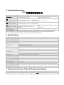
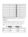
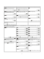
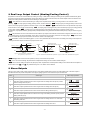
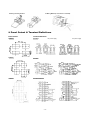
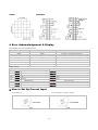
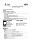
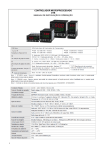
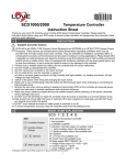
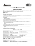
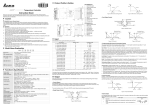
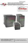
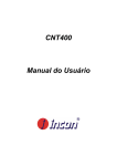
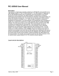
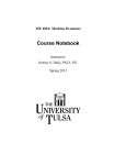
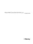
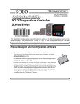
Series Temperature Controller Instruction Sheet Thank you very much for purchasing DELTA B Series. Please read this instruction sheet before using your B series to ensure proper operation and please keep this instruction sheet handy for quick reference. Precaution DANGER! Caution! Electric Shock! 1. Do not touch the AC terminals while the power is supplied to the controller to prevent an electric shock. 2. Make sure power is disconnected while checking the unit inside. 3. The symbol indicates that this Delta B Series Temperature Controller is protected throughout by DOUBLE INSULATION or REINFORCED INSULATION (equivalent to Class II of IEC 536). WARNING! This controller is an open-type temperature controller. Make sure to evaluate any dangerous application in which a serious human injury or serious property damage may occur. 1. Always use recommended solder-less terminals: Fork terminal with isolation (M3 screw, width is 7.0mm (6.0mm for DTB 4824), hole diameter 3.2mm). Screw size: M3 x 6.5 (With 6.8 x 6.8 square washer). Screw size for DTB4824: M3 x 4.5 (With 6.0 x 6.0 square washer). 2 Recommended tightening torque: 0.4 N.m (4kgf.cm). Applicable wire: Solid/twisted wire of 2 mm , 12AWG to 24AWG. Please be sure to tighten them properly. 2. Do not allow dust or foreign objects to fall inside the controller to prevent it from malfunctioning. 3. Never modify or disassemble the controller. 4. Do not connect anything to the “No used” terminals. 5. Make sure all wires are connected to the correct polarity of terminals. 6. Do not install and/or use the controller in places subject to: Dust or corrosive gases and liquid High humidity and high radiation Vibration and shock High voltage and high frequency 7. Must turn power off when wiring and changing a temperature sensor. 8. Be sure to use compensating wires that match the thermocouple types when extending or connecting the thermocouple wires. 9. Please use wires with resistance when extending or connecting a platinum resistance thermometer (RTD). 10. Please keep the wire as short as possible when wiring a platinum resistance thermometer (RTD) to the controller and please route power wires as far as possible from load wires to prevent interference and induced noise. 11. This controller is an open-type unit and must be placed in an enclosure away from high temperature, humidity, dripping water, corrosive materials, airborne dust and electric shock or vibration. 12. Please make sure power cables and signals from instruments are all installed properly before energizing the controller, otherwise serious damage may occur. 13. Please do not touch the terminals in the controller or try to repair the controller when power is applied to prevent an electric shock. 14. Wait at least one minute after power is disconnected to allow capacitors to discharge, and please do not touch any internal circuit within this period. 15. Do not use acid or alkaline liquids for cleaning. Please use a soft, dry cloth to clean the controller. 16. This instrument is not furnished with a power switch or fuse. Therefore, if a fuse or power switch is required, install the protection close to the instrument. Recommended fuse rating: Rated voltage 250 V, Rated current 1 A. Fuse type: Time-lag fuse 17. This controller does not provide overcurrent protection. Use of this product requires that suitable overcurrent protection device(s) must be added to ensure compliance with all relevant electrical standards and codes. (Rated 250 V, 15 Amps max). A suitable disconnecting device should be provided near the controller in the end-use installation. Display, LED & Pushbuttons -1- Ordering Information DTB 1 2 3 4 5 6 DTB Series DTB: Delta B Series Temperature Controller 1 2 3 4 4824: 1/32 DIN W48 × H24mm 4848: 1/16 DIN W48 × H48mm Panel size (W×H) 5 1st output group selection 6 2nd output group selection 7 EVENT inputs / CT function (optional) 8 Power supply 7 8 4896: 1/8 DIN W48 × H96mm 9696: 1/4 DIN W96 × H96mm R: Relay output, SPDT (SPST: 1/16 DIN and 1/32 DIN size), 250VAC, 5A V: Voltage pulse output, 14V +10% ~ -20% (Max. 40mA) C: DC current output , 4 ~ 20mA L: Linear voltage output, 0 ~ 5V, 0 ~ 10VDC R: Relay output, SPDT (SPST: 1/16 DIN and 1/32 DIN size), 250VAC, 5A V: Voltage pulse output, 14V +10% ~ -20% (Max. 40mA) None: No EVENT input , No CT (Current transformer) E: EVENT input is provided, No CT (Current transformer) T: CT (Current transformer) is provided, No EVENT input V: Valve control None: AC 100 ~ 240V; D: DC24V Note 1: DTB4824 series: no optional function provided and no extra alarm output supported, but user can set 2nd output as alarm mode. Note 2: DTB4848 series: only one alarm output when optional function supported, but user can set 2nd output as 2nd alarm output. Note 3: “Valve control” with feedback selection is only available for DTB4896RRV, DTB9696RRV. Specifications Input voltage AC100 ~ 240V, 50/60Hz; DC24V±10% Operation voltage rrange Rated voltage: AC 85% ~ 110%; DC 90 ~ 110% Power consumption 5VA max. Memory Protection EEPROM 4K bit (non-volatile memory (number of writes: 100,000) Display method 2 line x 4 character 7-segment LED display Process value (PV): Red color, Set point (SV): Green color Thermocouple: K, J, T, E, N, R, S, B, L, U, TXK Sensor type 3-wire Platinum RTD: Pt100, JPt100 Analog input: 0 ~ 5V, 0 ~ 10V, 0 ~ 20 m A, 4 ~ 20 m A, 0 ~ 50mV Control mode PID, ON/OFF, Manual or PID program control (Ramp/Soak control) Relay output: SPDT (SPST: 1/16 DIN and 1/32 DIN size), Max. load 250VAC, 5A resistive load Control output Voltage pulse output: DC 14V, Max. output current 40mA Current output: DC 4 ~ 20m A output (Load resistance: Max. 600) Linear voltage output: 0 ~ 10V Display accuracy 0 or 1 digit to the right of the decimal point (selectable) Sampling rate Analog input: 150 msec/ per scan Thermocouple or Platinum RTD: 400 msec/per scan RS-485 communication MODBUS ASCII / RTU communication protocol Vibration resistance 10 to 55Hz, 10m/s for 10min, each in X, Y and Z directions 2 2 Shock resistance Max. 300m/ s , 3 times in each 3 axes, 6 directions Ambient temperature 0 C ~ +50 C Storage temperature -20 C ~ +65 C o o o o Altitude 2,000m or less Relative humidity 35% ~ 80% (non-condensing) Panel protection level IP65 Temperature Sensor Type & Temperature Range Input Temperature Sensor Type Register Value 0 ~ 50mV Analog Input 17 LED Display Temperature Range -999 ~ 9,999 -2- Input Temperature Sensor Type Register Value 4 ~ 20mA Analog Input 16 LED Display Temperature Range -999 ~ 9,999 0 ~ 20mA Analog Input 15 -999 ~ 9,999 0V ~ 10V Analog Input 14 -999 ~ 9,999 0V ~ 5V Analog Input 13 -999 ~ 9,999 Platinum Resistance (Pt100) 12 -200 ~ 600 C Platinum Resistance (JPt100) 11 -20 ~ 400 C Thermocouple TXK type 10 -200 ~ 800 C Thermocouple U type 9 -200 ~ 500 C Thermocouple L type 8 -200 ~ 850 C Thermocouple B type 7 100 ~ 1,800 C Thermocouple S type 6 0 ~ 1,700 C Thermocouple R type 5 0 ~ 1,700 C Thermocouple N type 4 -200 ~ 1,300 C Thermocouple E type 3 0 ~ 600 C Thermocouple T type 2 -200 ~ 400 C Thermocouple J type 1 -100 ~ 1,200 C Thermocouple K type 0 -200 ~ 1,300 C o o o o o o o o o o o o o Note 1: An internal 249 precision resistor for the current input is built-in, please refer to the item “How To Set Up Current Input”. Note 2: (Operation mode) must be set if user wishes to specify decimal point position. Except for the thermocouple B, S, R type, the decimal point positions of all the other thermocouple type input sensors can be set. The default range of analog input is -999 ~ 9,999. For example, when a 0 ~ 20mA analog input is selected as the input temperature sensor type, -999 indicates 0mA and 9,999 indicates 20mA. If change the input range to 0 ~ 2,000, then 0 indicates 0mA and 2,000 indicates 20mA. One display scale is equal to 0.01mA. Operation There are three modes of operation: operation, regulation and initial setting. When power is applied, controller gets into the operation mode. Press the key to switch to regulation mode. If the initial setting mode. Pressing the operation mode. key is pressed for more than 3 seconds, controller will switch to the key while in the regulation mode or initial setting mode, forces the controller to return to the PV/SV: Sets the temperature set point and displays the temperature process value. Use Setting method: While in any function mode, press the keys to set the temperature set point. key to select the desired function and use the keys to change settings. Press key to save the changes. The next flow chart shows how to switch for settings and internal functions: Regulation Mode Operation Mode Use Auto-tuning (Set in PID control and RUN mode) Press key to set temperature set Set input type point Press 4 groups PID modes (n=0~3). When n=4, PID control is auto regulated. Press Initial Setting Mode Control setting RUN or STOP Press -3- Press Set temperature unit (Not display when in analog input) Press Regulation Mode Operation Mode PD control offset setting (When PID control is ON and Ti=0, set the value of PdoF.) Press (PID program control and setting. Press Press Press Switch setting for feedback signal of value (Displayed with valve control is ON) Press Select heating/cooling control or dual loop output control Press Press Press Press Press Alarm 1 mode setting Alarm 2 mode setting Alarm 3 mode setting Set system alarm Enable/disable communication write Press Press Display and adjust output value of 1st ASCII, RTU communication formats output group selection (Display in PID control mode and manual RUN mode) Press Press nd Communication address setting Display and adjust output value of 2 output group (Display in dual loop PID control mode and manual RUN mode) Valve Deadband setting (Displayed when valve control is ON) Press function Time setting for valve from full close to full open (Displayed when valve control is ON) Press Press Setting lock mode Automatically regulate feedback value (Displayed when valve control is ON) Press Lower-limit alarm 3 (This parameter is available only when ALA3 function is enabled.) Select control mode (See “Pattern and Set Editing Selection” for detail) Upper-limit alarm 3 (This parameter is available only when ALA3 function is enabled.) Deadband (Set in Dual Loop output control mode) Press Press Lower-limit alarm 2 (This parameter is available only when ALA2 function is enabled.) P value of 1 & 2 output group during dual loop output control nd st P value of 2 output group=(P value of 1 output group x COEF Press Lower-limit alarm 1 (This parameter is available only when ALA1 function is enabled.) Press Set lower-limit of temperature range Upper-limit alarm 2 (This parameter is available only when ALA2 function is enabled.) nd Press Press nd st Press Control cycle setting of 2 output group (Set in PID control and Dual Loop output control mode) Press Press Upper-limit alarm 1 (This parameter is available only when ALA1 function is enabled.) or Heating/Cooling control cycle setting (Set in PID control mode) Press Time Press Cooling hysteresis setting (Set in ON/OFF control mode) Press Set upper-limit of temperature range Decimal point position selection (except for B, S, R type, all the other types can be set) Heating hysteresis setting (Set in ON/OFF control mode) Press Initial Setting Mode Start pattern setting Press -4- Press Regulation Mode Operation Mode Initial Setting Mode In case of using an external CT, the Upper-limit regulation of valve output controller displays the current value being with feedback to controller (Display when measured by CT, if the control output is ON valve signal feedback function is ON) Press Press Communication baud rate setting to return to set target temperature Valve output with feedback (Display Lower-limit regulation of valve output when valve feedback function is ON) with feedback to controller (Display when valve signal feedback function is ON) Press Regulate temperature deviation value Press Press Press Press Press Parity bit setting back to target temperature Stop bit setting Regulate upper-limit of analog output value (The setting is displayed when in analog output) Press Data length setting DA value feedback of valve (Display when valve feedback function is ON) Press Press to return to input type setting Regulate lower-limit of analog output value (The setting is displayed when in analog output) Press to return to auto-tuning mode 1 Scale = 2.8uA = 1.3mV for tuning output value PID mode selection: any one of 4 groups PID modes (n = 0 ~ 3) can be selected. When n = 4, program will automatically select 1 group PID that is most useful for target temperature. PID setting: n=3 PID setting: n=0 Seletc n=0~4 to decide PID mode Press Press Proportion band setting: n=0 Press Ti setting: n=0 Press Press Pattern and step editing selection: edit in Select desired editing pattern number. Select OFF Press and continue to set. Press Press Integral deviation setting: n=3 AT setting. back to PID deviation setting Press back to PID deviation setting parameter. The following display is the example operation of pattern No. 0. Edit temperature of step No.0 of pattern No.0 select number Exit pattern and step editing selection Switch to Press Td setting: n=3 Integral deviation setting: n=0 AT setting. 0~3 groups of PID Press Ti setting: n=3 Td setting: n=0 Press Proportion band setting: n=3 Press Select actual step No. when program control is executing Edit time of step No.0 of pattern No.0. Unit: hh.mm Press Set additional execution cycle number (0~99) Set step No. 07 in order Press Set link pattern. OFF indicates the program end. Edit temperature of step No.7 of pattern No.0 Press Press Edit time of step No.7 of pattern No.0 Unit: hh.mm Press to set actual step No. Press -5- to return to pattern No. editing mode Dual Loop Output Control (Heating/Cooling Control) Temperature control can be achieved either by heating or cooling. In DTB series, heating and cooling can be operated simultaneously (Dual Loop output control) to perform temperature control. When Dual Loop output control are used, two control outputs must be connected to the heating and cooling devices. Please refer to the following for the operation: : This parameter is used to select heating or cooling action if operate either heating or cooling function in this controller. When , 1st output group is heating (reverse) control, and when selecting selecting moment, 2nd output group is regarded as an alarm output. If user select control function in this controller. When selecting , 1st output group is cooling (forward) control. At this or , it indicates that user can operate Dual Loop output , 1st output group is heating (reverse) control and 2nd output group is cooling (forward) , 1st output group is cooling (forward) control and 2nd output group is heating (reverse) control. control. When selecting In DTB series, P (Proportional Band), I(Integral Time) and D(Derivative Time) parameters are automatically set by using the Auto-tuning (AT) function. : This parameter is for the control mode that must be Dual Loop output control with PID control method configured. The value of P, I and and the value D of 1st output group can be set immediately. The P value of 2nd output group is equal to (P value of 1st output group) x of I and D of 2nd output group are the same as the value of I and D of 1st output group. : Dead Band, shown as the following figure 1, 2 and 3. This parameter sets an area in which the heating and cooling control output is 0 centering around the set point in a Dual Loop output control mode. Dead band Heating hysteresis Dead band: dead Output band width=positive Output Dead band: dead band width=negative Cooling hysteresis ON Heating Cooling OFF PV Set point Figure 1. Output operation of ON/OFF control during dual loop output control Heating Cooling Heating PV 0 Cooling PV 0 Set point Set point Figure 2. PID control, Dead Band is positive Figure 3. PID control, Dead Band is negative : Settings lock. To avoid incorrect operation, two key lock functions are provided. : Lock 1 can lock all settings. All parameters and temperature settings can be locked to disable changes. : Lock 2 can lock settings except the SV (Set point) value. All parameters and temperature settings can be locked with the exception of the SV value. Press and key simultaneously, the “Lock” status can be released. Alarm Outputs There are up to three groups of alarm outputs and each group allows eighteen alarm types in the initial setting mode. The alarm output is activated whenever the process temperature value (PV) is getting higher or lower than the set point of alarm limit. Set value Alarm Type Alarm output operation 0 Alarm function disabled 1 Deviation upper- and lower-limit: This alarm output operates when PV value is higher than the setting value SV+(AL-H) or lower than the setting value SV-(AL-L). 2 Output is OFF Deviation upper-limit: This alarm output operates when PV value is higher than the setting value SV+(AL-H). 3 Deviation lower-limit: This alarm output operates when PV value is lower than the setting value SV-(AL-L). 4 Reverse deviation upper- and lower-limit: This alarm output operates when PV value is in the range of the setting value SV+(AL-H) and the setting value SV-(AL-L). 5 6 Absolute value upper- and lower-limit: This alarm output operates when PV value is higher than the setting value AL-H or lower than the setting value AL-L. Absolute value upper-limit: This alarm output operates when PV value is higher than the setting value AL-H. -6- ON OFF SV-(AL-L) SV SV+(AL-H) SV SV+(AL-H) ON OFF ON OFF SV-(AL-L) SV ON OFF SV-(AL-L) SV SV+(AL-H) ON OFF AL-L AL-H ON OFF AL-H Set value Alarm Type Alarm output operation ON OFF 7 Absolute value lower-limit: This alarm output operates when PV value is lower than the setting value AL-L. 8 Deviation upper- and lower-limit with standby sequence: This alarm output operates when PV value reaches set point (SV value) and the value is higher than the setting value SV+(AL-H) or lower than the setting value SV-(AL-L). OFF Deviation upper-limit with standby sequence: This alarm output operates when PV value reaches set point (SV value) and the reached value is higher than the setting value SV+(AL-H). OFF Deviation lower-limit with standby sequence: This alarm output operates when PV value reaches the set point (SV value) and the reached value is lower than the setting value SV-(AL-L). OFF 9 10 11 12 13 AL-L ON SV-(AL-L) SV-(AL-L) Hysteresis lower-limit alarm output: This alarm output operates if PV value is lower than the setting value SV-(AL-H). This alarm output is OFF when PV value is higher than the setting value SV-(AL-L). ON OFF CT alarm output: This alarm operates when the current measured by transformer (CT) is lower than AL-L or higher than AL-H (This alarm output is available only for the controller with current transformer). ON OFF 15 When RAMP UP status happens to PID program control, alarm output is ON. 16 When RAMP DOWN status happens to PID program control, alarm output is ON. 17 When SOAK status happens to PID program control, alarm output is ON. 18 When RUN status happens to PID program control, alarm output is ON. SV SV+(AL-H) ON ON OFF When program control is end status, alarm output is ON. SV+(AL-H) ON Hysteresis upper-limit alarm output: This alarm output operates if PV value is higher than the setting value SV+(AL-H). This alarm output is OFF when PV value is lower than the setting value SV+(AL-L). 14 SV SV AL-L AL-H AL-H AL-L AL-L SV AL-H Note: AL-H and AL-L include AL1H, AL2H, AL3H and AL1L, AL2L, AL3L Current Transformer (CT) Function The Current Transformer (CT) function is used with the alarm output. When using a current transformer (CT) with the controller, change the corresponding alarm output mode to mode 13 (alarm output set value is 13), then turn to operation mode and set the current lower-limit and current upper-limit. You can set current alarm range between 0.5A ~ 30A, display resolution is 0.1A and measure accuracy is +/- 0.5A. EVENT Inputs Function There are two optional event inputs (contact inputs) supported (EVENT1and EVENT2) in DTB series. EVENT1 : RUN/STOP operation can be executed by RUN/STOP parameters (Operation Mode) or via the communication. User also can control RUN/STOP operation by EVENT 1 in DTB series. The control output is ON if the circuit of EVENT 1 is open when the controller is operating. Otherwise, the controller will stop output if the circuit of EVENT 1 is short or when the system parameter of the controller is set to STOP mode. EVENT2 : DTB series allows user can switch two temperature setting value by changing the status (open/short) of EVENT 2. Each temperature setting value has independent control parameters. PID Program Control (Ramp/Soak Program Control) Description of Function and Parameters Setting: PID program control by 8 patterns (Pattern No. 0~7) is supported in DTB series. Each pattern contains 8 steps (step No. 0 ~ 7), one Link Pattern parameter, one Cycle parameter and one Actual Step parameter. is in operation mode and it is used to set the Start Pattern of PID program control (This parameter appear in Start Pattern : mode only). Steps : Include set point X and execution time T, these two parameters setting. The set point (SV) should reach temperature X after the period of execution time T. If the set point is the same as the result of the previous setting, then it is called Soak program control. If not, then it is called Ramp program control. Therefore, PID program control is also called Ramp/Soak program control. The default of step No. 0 in this controller is Soak program control. The controller will control the temperature (PV) to reach the set point X and then keep the temperature at set point X. The period of execution time is time T which provided by step No. 0. Link Pattern Parameter : For example, when set No. 0. If set to to 2, it indicates that pattern No. 2 will execute next after the execution of pattern , it indicates the program will stop after executing the current pattern and the temperature will keep at the set point of -7- the last step. Cycle Parameter : Additional execution cycle number. For example, when set twice in addition. Include origin one time execution, total execute three times. to 2, it indicates that pattern No. 4 should execute Actual Step Parameter : Execution step number per pattern (can set to 0 ~ 7). For example, when set No 7 will not execute other steps than step 0 to step2. Execution : When is set to to 2, it indicates that pattern , the program will start to execute in order from the step 0 of start pattern. When is set to , the program will stop and the control output is disabled. When is set to , the program will stop and the temperature at that time will be controlled at the set point before program stop. Select again, then the program will restart and execute from step 0 of start pattern. When is set to , the program will hold and the temperature at that time will be controlled at the set point before program hold. again, then the program will follow the step before hold and start to execute through the rest of the time. Select Display : During PID program control, the SV default display is P-XX, P indicates the current execution pattern and XX indicates the current execution step. Press to change the display item. After select , press key, and then the temperature set point of the current execution step will display on SV display. After select , press key, and then the residual time of the current execution step will display on SV display. PID Control One group can be selected from any one of 4 groups PID parameters (P, I, D, IOF) for PID control. After AT, PID value and temperature setting will be stored in the selected one group. ~ : PIDn, n = 0 ~ 4 from which 0 ~ 3 correspond to each PID parameter. : n = 4, auto PID parameter. Program will automatically select a most useful PID parameter based on current temperature setting. Displayed SV values correspond to ~ ~ : Temperature setting corresponded to the selected PID parameter via user-defined or AT. Valve Control: When use valve control as output control, there are 2 Relay outputs for motor forward/reverse control, one (output 1) for valve open the other (output 2) for valve close. The output volume is controlled by valve open/close and it can be set with feedback function enabled or disabled. When feedback is disabled, output 1 will keep output while valve fully opens and output 2 will keep output while valve fully closes. But if feedback is enabled, please follow the parameter setting for valve control as follows: : Time for valve from full close to full open. : Dead Band setting of valve. The value of current valve output minus previous one must be greater than Dead Band value; otherwise, valve will remain OFF. : Signal feedback setting, ON for enabling feedback and OFF for disabling feedback. When set to ” 1”, it means signal feedback function is activated and will come up selections as follows: : Upper/Lower limit of valve feedback by auto-tuning. : D/A value when value fully opens. Set must set to for showing up this selection. to be ”1” for auto setting or ”0” for manual setting. : D/A value when value fully closes. Set to be ”1” for auto setting or “0” for manual setting. Note: If feedback function setting is with problem, program will see the setting as feedback disabled. RS-485 Communication 1. 2. 3. 4. Supporting transmission speed: 2,400, 4,800, 9,600, 19,200, 38,400bps Non-supported formats: 7, N, 1 or 8, O, 2 or 8, E, 2 Communication protocol: Modbus (ASCII or RTU) Function code: 03H to read the contents of register (Max. 8 words). 06H to write 1 (one) word into register. 02H to read the bits data (Max. 16 bits). 05H to write 1 (one) bit into register. 5. Address and Content of Data Register: Address 1000H Content Process value (PV) Explanation Measuring unit is 0.1, updated one time in 0.4 second The following reading value display indicates error occurs: 8002H : Initial process (Temperature value is not got yet) 8003H : Temperature sensor is not connected 8004H : Temperature sensor input error -8- Address Content Explanation 8006H : Cannot get temperature value, ADC input error 8007H : Memory read/write error 1001H o o Set point (SV) Unit is 0.1, C or F 1002H Upper-limit of temperature range The data content should not be higher than the temperature range 1003H Lower-limit of temperature range The data content should not be lower than the temperature range 1004H Input temperature sensor type Please refer to the contents of the “Temperature Sensor Type and Temperature Range” for detail 1005H Control method 0: PID, 1: ON/OFF, 2: manual tuning, 3: PID grogram control 1006H Heating/Cooling control selection 0: Heating, 1: Cooling, 2: Heating/Cooling, 3: Cooling/Heating 1007H 1st group of Heating/Cooling control cycle 0 ~ 99, 0:0.5 sec 1008H 2nd group of Heating/Cooling control cycle 0 ~ 99, 0:0.5 sec 1009H PB Proportional band 0.1 ~ 999.9 100AH Ti Integral time 0 ~ 9,999 100BH Td Derivative time 0 ~ 9,999 100CH Integration default 0 ~ 100%, unit is 0.1% 100DH Proportional control offset error value, when Ti =0 0 ~ 100%, unit is 0.1% 100EH The setting of COEF when Dual Loop output control are used 0.01 ~ 99.99 100FH The setting of Dead band when Dual Loop output control are used -999 ~ 9,999 1010H Hysteresis setting value of the 1st output group 0 ~ 9,999 1011H Hysteresis setting value of the 2nd output group 0 ~ 9,999 1012H Output value read and write of Output 1 Unit is 0.1%, write operation is valid under manual tuning mode only. 1013H Output value read and write of Output 2 Unit is 0.1%, write operation is valid under manual tuning mode only. 1014H Upper-limit regulation of analog linear output 1 Unit = 2.8uA (Current Output) = 1.3mV (Linear Voltage Output) 1015H Lower-limit regulation of analog linear output 1 Unit = 2.8uA (Current Output) = 1.3mV (Linear Voltage Output) 1016H Temperature regulation value -999 ~ +999, unit: 0.1 1017H Analog decimal setting 0~3 1018H Time for valve from full open to full close 0.1 ~ 999.9 1019H Dead Band setting of valve 0 ~ 100%; unit: 0.1% 101AH Upper-limit of feedback signal set by valve 0 ~ 1,024 101BH Lower-limit of feedback signal set by valve 0 ~ 1,024 101CH PID parameter selection 0~4 101DH SV value corresponded to PID value Only valid within available range, unit: 0.1 scale 1020H Alarm 1 type Please refer to the contents of the “Alarm Outputs” for detail 1021H Alarm 2 type Please refer to the contents of the “Alarm Outputs” for detail 1022H Alarm 3 type Please refer to the contents of the “Alarm Outputs” for detail 1023H System alarm setting 0 : None (default), 1~3 : Set Alarm 1 to Alarm 3 1024H Upper-limit alarm 1 Please refer to the contents of the “Alarm Outputs” for detail 1025H Lower-limit alarm 1 Please refer to the contents of the “Alarm Outputs” for detail 1026H Upper-limit alarm 2 Please refer to the contents of the “Alarm Outputs” for detail 1027H Lower-limit alarm 2 Please refer to the contents of the “Alarm Outputs” for detail 1028H Upper-limit alarm 3 Please refer to the contents of the “Alarm Outputs” for detail 1029H Lower-limit alarm 3 Please refer to the contents of the “Alarm Outputs” for detail 102AH Read LED status b0 : Alm3, b1: Alm2, b2: F, b3: ℃, b4: Alm1, b5: OUT2, b6: OUT1, b7: AT 102BH Read pushbutton status b0 : Set, b1 : Select, b2 : Up, b3 : Down. 0 is to push 102CH Setting lock status 0 : Normal, 1 : All setting lock, 11 : Lock others than SV value 102DH CT read value Unit: 0.1A 102FH Software version V1.00 indicates 0x100 -9- Address Content Explanation 1030H Start pattern number 0~7 1032H Read program Step time left (second) 1033H Read program Step time left (minute) 1034H Read present executing program step number 1035H Read present executing program pattern number 1036H Read program dynamic set value 1040H~ 1047H Actual step number setting inside the correspond pattern 1050H~ 1057H Cycle number for repeating the execution of the 0 ~ 99 indicate that this pattern has been executed for 1 ~ 100 times correspond pattern 1060H~ 1067H Link pattern number setting of the correspond pattern 0 ~ 8, 8 indicates the program end. 0~7 indicates the next execution pattern number after executing the current pattern 2000H~ 203FH Pattern 0~7 temperature set point setting Pattern 0 temperature is set to 2000H ~ 2007H -999 ~ 9,999 2080H~ 20BFH Pattern 0~7 execution time setting Pattern 0 time is set to 2080H~2087H Time 0 ~ 900 (1 minute per scale) 0 ~ 7 = N, indicate that this pattern is executed from step 0 to step N 6. Address and Content of Bit Register: (First bit of reading will put into LSB, Write data = FF00H for bit set, 0000H for bit clear) Address Content Explanation 0800H Read AT LED status 0:OFF; 1: ON 0801H Read Output 1 LED status 0: OFF; 1:ON 0802H Read Output 2 LED status 0:OFF; 1: ON 0803H Read Alarm 1 LED status 0804H Read F LED status 0805H 0: OFF; 1:ON o 0: OFF; 1: ON Read C LED status o 0: OFF; 1: ON 0806H Read Alarm 2 LED status 0: OFF; 1: ON 0807H Read Alarm 3 LED status 0: OFF; 1: ON 0808H Read SET key status 0: Press down 0809H Read FUNCTION key status 0: Press down 080AH Read UP key status 0: Press down 080BH Read DOWN key status 0: Press down 080CH Read Event 1 status 1: Event action 080DH Read Event 2 status 1: Event action 080EH Read System Alarm status 0810H Communication write-in selection 1: Alarm action Communication write in disabled: 0 (default), Communication write in enabled: 1 0811H Temperature unit display selection 0812H Decimal point position selection Except for the thermocouple B, S, R type, all the other thermocouple type are valid. (0 or 1) 0813H AT setting OFF: 0 (default), ON : 1 0814H Control RUN/STOP setting 0: STOP, 1: RUN (default) 0815H STOP setting for PID program control 0: RUN (default), 1: STOP 0816H Temporarily STOP for PID program control 0: RUN (default), 1: Temporarily STOP 0817H Valve feedback setting status 0: w/o feedback (default), 1: feedback function 0818H Auto-tuning valve feedback status 0: Stop AT (default), 1: Start AT o o C/linear input (default): 1; F: 0 7. Communication Transmission Format: Command Code: 02: read N bits, 05: write 1 bit, 03: read N words, 06: write 1 word. - 10 - ASCII Mode: Read command Read command response Write command Write command response STX ’:’ ’:’ STX ’:’ ’:’ STX ’:’ ’:’ STX ’:’ ’:’ ADR 1 ‘0’ ‘0’ ADR 1 ‘0’ ‘0’ ADR 1 ‘0’ ‘0’ ADR 1 ‘0’ ‘0’ ADR 0 ‘1’ ‘1’ ADR 0 ‘1’ ‘1’ ADR 0 ‘1’ ‘1’ ADR 0 ‘1’ ‘1’ CMD 1 ‘0’ ‘0’ CMD 1 ‘0’ ‘0’ CMD 1 ‘0’ ‘0’ CMD 1 ‘0’ ‘0’ CMD 0 ‘6’ ‘5’ CMD 0 ‘1’ ‘0’ CMD 0 ‘3’ ‘2’ CMD 0 ‘3’ ‘2’ ‘1’ ‘0’ ‘0’ ‘0’ ‘0’ ‘8’ Number of data (count by byte) ‘0’ ‘1’ ‘0’ ‘0’ ‘0’ ‘0’ Number of data (word/Bit) ‘0’ ‘0’ ‘2’ ‘9’ LRC 1 ‘E’ ‘D’ Starting data address ‘4’ ‘2’ ‘0’ ‘1’ Starting data address ‘0’ ‘8’ ‘0’ ‘1’ Starting data address ‘6’ ‘5’ ‘1’ ‘0’ ‘0’ ‘8’ ‘0’ ‘1’ ‘1’ ‘7’ ‘1’ ‘0’ ‘1’ ‘0’ ‘F’ ‘0’ ‘0’ ‘F’ ‘0’ ‘F’ ‘0’ ‘4’ ‘1’ ‘3’ ‘F’ ‘3’ ‘F’ ‘0’ ‘0’ ‘E’ ‘0’ ‘E’ ‘0’ LRC 0 ‘A’ ‘C’ END 1 CR CR END 0 LF LF Start address data 1000H/081xH Data content ‘0’ Address data 1001H ‘0’ LRC 1 ‘0’ LRC1 ‘0’ ‘8’ ‘0’ ‘F’ ‘E’ Data content LRC1 ‘8’ ‘0’ ‘F’ ‘E’ LRC 0 ‘D’ ‘3’ LRC 0 ‘D’ ‘3’ ‘E’ END 1 CR CR END 1 CR CR END 0 LF LF END 0 LF LF LRC 0 ‘3’ ‘3’ END 1 CR CR END 0 LF LF LRC checksum: LRC check is the added sum from “Address” to “Data content”. For example, 01H + 03H + 10+ 00H + 00H + 02H = 16H, then take the complementary of 2, EAH. RTU Mode: Read command Read command response Write command Write command response ADR 01H 01H ADR 01H 01H ADR 01H 01H ADR 01H 01H CMD 03H 02H CMD 03H 02H CMD 06H 05H CMD 06H 05H Starting data address 10H 08H 04H 02H Starting data address 08H 08H 01H 10H Starting data address 10H 10H Number of data (count by byte) 10H 00H 01H 10H Number of data (word/Bit) 00H 00H 03H FFH 02H 09H CRC 1 C0H BBH CRC 0 CBH A9H Start address data 1000H/081xH 01H 17H F4H 01H Data content 03H FFH 20H 00H Data content 20H 00H Address data 1001H 03H CRC 1 DDH 8FH CRC 1 DDH 8FH 20H CRC 0 E2H 9FH CRC 0 E2H 9FH CRC 1 BBH 77H CRC 0 15H 88H Default Communication Response Setting Write hex value 1234 into register at 472AH and 1234 again into register at 474EH. Re-power DTB to complete the default setting. Mounting 1. 2. 3. 4. Insert the controller through the panel cutout. Insert the mounting bracket into the mounting groove at the top and bottom of the controller Push the mounting bracket forward until the bracket stops at panel wall. Insert and tighten screws on bracket to secure the controller in place. (The screw torque should be 0.8kgf-cm to 1.5kgf-cm) - 11 - Installing mounting bracket: CT Wiring Method (if CT function is selected) Panel Cutout & Terminal Definitions Panel Cutout Terminal Definition DTB4824 DTB4824 DTB4848 DTB4848 DTB4896 DTB4896/DTB9696 DC power supply - 12 - AC power supply DTB9696 DTB9696RRV Error Acknowledgement & Display Communication error code response description: Error Status 102EH / 4750H PV read back 1000H / 4700H Error status 0001H M/A PV unstable 0002H 8002H Re-initial, no temperature at this time 0003H 8003H Input sensor did not connect 0004H 8004H Input signal error 0005H N/A Over input range 0006H 8006H ADC fail 0007H N/A EEPROM read/write error Display message: Power ON Normal display PV DTB series, Firmware V1.50 Present value SV Output VR type with Event option Set value Sensor didn’t connect Input error PV No Error SV Connect Input PV Error SV EEPROM EEPROM error Input over range PV flash when over How to Set Up Current Input For normal input For current input (4 ~ 20mA, 0 ~ 20mA) - 13 -