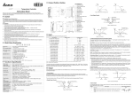
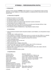
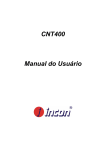
1
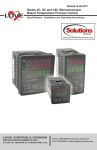
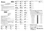
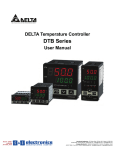
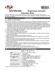
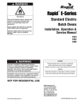
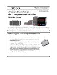
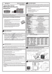
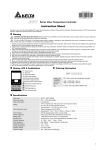
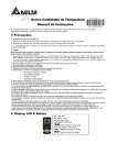
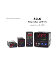
Bulletin E-90-BPC
Series 4B, 8B, 16B and 32B Microprocessor
Based Temperature Process Control
Specifications - Installation and Operating Instructions
LOVE CONTROLS
A DIV. OF DWYER INSTRUMENTS INC.
P.O. BOX 338 - MICHIGAN CITY, INDIANA 46361, U.S.A.
Phone: 219/879-8000 www.love-controls.com
Fax: 219/872-9057 e-mail:[email protected]
TABLE OF CONTENTS
Model Number Identification. . . . . . . . . . . . . . . . . . . . . . . . . . . . . . . . . . . . . . . . . . . 3
Getting Started . . . . . . . . . . . . . . . . . . . . . . . . . . . . . . . . . . . . . . . . . . . . . . . . . . . . . 3
Installation. . . . . . . . . . . . . . . . . . . . . . . . . . . . . . . . . . . . . . . . . . . . . . . . . . . . . . . . . 4
Panel Cutout Dimensions . . . . . . . . . . . . . . . . . . . . . . . . . . . . . . . . . . . . . . . . . . . . . . . . . 4
Mounting . . . . . . . . . . . . . . . . . . . . . . . . . . . . . . . . . . . . . . . . . . . . . . . . . . . . . 5
Wiring Diagrams . . . . . . . . . . . . . . . . . . . . . . . . . . . . . . . . . . . . . . . . . . . . . . . . . . . . . . 6-7
Front Panel Key Functions . . . . . . . . . . . . . . . . . . . . . . . . . . . . . . . . . . . . . . . . . . . . 8
Security Features . . . . . . . . . . . . . . . . . . . . . . . . . . . . . . . . . . . . . . . . . . . . . . . . . . . 8
Control Operation Description . . . . . . . . . . . . . . . . . . . . . . . . . . . . . . . . . . . . . . . 9-10
Programming and Operation for Ramp and Soak Feature . . . . . . . . . . . . . . . . 11-13
Programming and Operation for PID Function . . . . . . . . . . . . . . . . . . . . . . . . . . . . 14
Description of Menu Structure . . . . . . . . . . . . . . . . . . . . . . . . . . . . . . . . . . . . . . . . 15
Operation Menu. . . . . . . . . . . . . . . . . . . . . . . . . . . . . . . . . . . . . . . . . . . . . . . . . 15-16
Regulation Menu . . . . . . . . . . . . . . . . . . . . . . . . . . . . . . . . . . . . . . . . . . . . . . . . 17-19
Initial Setting Menu . . . . . . . . . . . . . . . . . . . . . . . . . . . . . . . . . . . . . . . . . . . . . . 20-22
Alarm Output Description . . . . . . . . . . . . . . . . . . . . . . . . . . . . . . . . . . . . . . . . . . . . 23
Communication Register List . . . . . . . . . . . . . . . . . . . . . . . . . . . . . . . . . . . . . . 24-25
Diagnostic Error Messages . . . . . . . . . . . . . . . . . . . . . . . . . . . . . . . . . . . . . . . . . . 26
Specifications . . . . . . . . . . . . . . . . . . . . . . . . . . . . . . . . . . . . . . . . . . . . . . . . . . . . . 29
Input Sensor Ranges . . . . . . . . . . . . . . . . . . . . . . . . . . . . . . . . . . . . . . . . . . . . . . . 30
Precautions. . . . . . . . . . . . . . . . . . . . . . . . . . . . . . . . . . . . . . . . . . . . . . . . . . . . . . . 31
Page 2
MODEL NUMBER IDENTIFICATION
OPTIONS
OPTIONS
32B
OUTPUT 1
2 = Voltage Pulse
3 = Relay
5 = Current
6 = Linear Voltage
16B
OUTPUT 2
2 = Voltage Pulse
3 = Relay
OUTPUT 1
2 = Voltage Pulse
3 = Relay
5 = Current
6 = Linear Voltage
OPTIONS
OPTIONS
-LV = Low Voltage
Blank = none
1 = Event input
2 = Current Transformer
-LV = Low Voltage
OPTIONS
OPTIONS
8B
4B
OUTPUT 1
2 = Voltage Pulse
3 = Relay
5 = Current
6 = Linear Voltage
OUTPUT 2
2 = Voltage Pulse
3 = Relay
OUTPUT 1
2 = Voltage Pulse
3 = Relay
5 = Current
6 = Linear Voltage
OUTPUT 2
2 = Voltage Pulse
3 = Relay
OUTPUT 2
2 = Voltage Pulse
3 = Relay
OPTIONS
OPTIONS
Blank = none
1 = Event input
2 = Current Transformer
-LV = Low Voltage
Blank = none
1 = Event input
2 = Current Transformer
-LV = Low Voltage
GETTING STARTED
1. Install the control as described on page 4.
2. Wire your control following the instructions on pages 6-7. Please read the
Precautions section located at the end of this manual before wiring the control.
3. For best results when programming changes are necessary, make all changes to the
Initial Setting mode (Pages 20-22) before making changes to the Regulation Mode
(Pages 17-19) or Operation Mode (Pages 15-16). If any error messages occur, check
the Diagnostic Error Message Section (Page 26) for assistance.
Page 3
INSTALLATION
Mount the instrument in a location that will not be subject to excessive temperature, shock,
or vibration. All models are designed for mounting in an enclosed panel.
Select the position desired for the instrument on the panel. Prepare the panel by cutting and
deburring the required opening per the panel cut out dimensions listed below. Follow the
mounting instructions listed on page 5. Lastly, wire the controller per the appropriate wiring
diagram listed on page 6.
PANEL CUTOUT DIMENSIONS
Page 4
MOUNTING METHOD
Step 1:
From the front of the panel, slide the controller housing through
the cut out. The housing gasket should be against the housing
flange before installing.
Step 2:
Insert the mounting brackets into the mounting grooves on the
top and bottom of the controller (16B, 8B, and 4B). For the 32B,
slide the mounting collar over the housing from the rear of the
panel.
Step 3:
Push the mounting brackets forward until the bracket stops at
the panel wall.
Step 4:
Insert and tighten the screws on the bracket to secure the
controller in place. (The screw torque should be 0.8 kgf-cm).
Mounting Bracket Installation
16B/4B/8B Mounting Method
32 Mounting Method
Page 5
WIRING
Do not run thermocouple or other class 2 wiring in the same conduit as power leads. Use
only the type of thermocouple or RTD probe for which the control has been programmed.
Maintain separation between wiring of sensor, auxiliary in or out, and other wiring. See the
Initial Setting Menu for input selection.
For thermocouple input always use extension leads of the same type designated for your
thermocouple.
For supply connections use No. 16 AWG or larger wires rated for at least 75˚ C. Use
conductors only. All line voltage output circuits must have a common disconnect and be
connected to the same pole of the disconnect.
Input wiring for thermocouple, current, and RTD; and output wiring for current 14 VDC is
rated CLASS 2.
Control wiring as show below:
Terminal Identification
32B
16B
DC
AC
OUT1
NO
140VDC
OR
4-20MA
OR
0-10V +
COM
+
2 7
3 8
AC, No Event / CT Input
11
L
AC 100-24OV
50/60 HZ
5VA
-
EV1
SG
12
13
N
OUT2
DATA-
4 9
Tc
-
EV2
CT
RTD
+
1 6
5 10
ALM1
14
3A
RS-485
250VAC
15
COM
DATA+
AC, Event / CT Input
DC, No Event/CT Input
Page 6
3A
250VAC
Terminal Identification (Continued)
4B/8B
DC
AC
Wiring for 4 to 20 mA Transmitter Inputs
TRANSMITTER
POWER
SUPPLY
1
6
10
2
7
11
3
8
12
4
9
13
5 10 14
A-277
250 OHM
PRECISION
RESISTOR
Note: 16B terminal layout used in above example. Use appropriate terminal layout for
selected controller.
Page 7
FRONT KEY FUNCTIONS
Key functions are as follows:
INDEX: Pressing the INDEX key advances the display to the next menu item.
UP ARROW: Increments a value or changes a menu item. If pressed
during the Operation Mode, the set point value will be increased.
DOWN ARROW: Decrements a value or changes a menu item. If pressed
during the Operation Mode, the set point value will be decreased.
ENTER: Stores the value or item change. If not pressed, the previously
stored value or item will be retained. When pressed during the Operation
Mode, the controller switches to the Regulation Mode. If held for more
than 3 seconds during the Operation Mode, the controller switches to the
Initial Setting Mode. If pressed during the Regulation Mode or Initial Setting
Mode, the controller will return to the Operation Mode.
SECURITY FEATURES
The B series controller has two built in security lock settings to prevent unauthorized
personnel from changing parameter settings. These parameters are set in the Operation
Mode.
The LoC1 setting affects all parameters in the controller. If LoC1 setting is enabled, the
operator will have to unlock the controller to make any changes to the controller’s
parameters.
The LoC2 setting affects all parameters except the set point. If LoC2 setting is enabled, the
only parameter that the operator will be able to change is the set point. In order to change
any other parameters, the operator will have to unlock the control before making a change.
In order to unlock the control, the operator must depress the ENTER and INDEX key
simultaneously.
Page 8
CONTROL OPERATION DESCRIPTION
The HOME display is the normal display while the control is operating. If no errors or
functions are active, the HOME display will indicate the Process Variable (the temperature,
pressure, flow, %RH, etc.) that is being measured on the top display and the Set Variable on
the bottom display.
Items that can change the HOME display are the Ramp and Soak function and any error
messages. Descriptions of these special displays follow.
If the Ramp and Soak feature is active, then bottom display will show the current execution
pattern and current execution step. The UP and DOWN arrows can be pressed to change
the bottom display to show the Set Point (SP) of the current execution step or the Time
Remaining (r-ti) of the current execution step. After changing the bottom display to either the
Time Remaining or the Set Point, the ENTER key must be pressed to display the values.
Error Messages are shown on page 26.
OPTIONS
Event Input
When the controller is ordered with the Event Input Option (See page 3 for ordering
information), two event inputs are available. The event input is triggered by contact closure
between event 1 (EV1) or event (EV2) contact terminal and signal ground (SG) contact
terminal.
Event 1 controls the output operation of the control. When the event 1 contact terminals are
open, the output is active. When the event 1 contact terminals are closed, the output is deactivated. The outputs can also be controlled via the Run/Stop parameter using the front
keypad or by using the RS-485 communications.
Event 2 allows the user to switch between two temperature set points. Each temperature set
point has independent control parameters.
Current Transformer Alarm Function
The current transformer option allows the user to have an alarm contact trigger due to a loss
of current or a surge in current to the control output. When using the current transformer
input, the desired alarm contact should be set to alarm type 13 in the Initial Setting Menu
(Page 21). The current transformer should be wired according to the appropriate wiring
diagram on page 6 and page 7. The high and low alarm set points can be set from 0.5 to 30
Amps. The display resolution is 0.1 Amps and the accuracy is ±0.5 Amps with the included
current transformer.
Page 9
Heating, Cooling or Dual Loop Control
Temperature Control can be achieved by either heating or cooling. In the B series controllers,
heating and cooling can be operated simultaneously using Dual Loop Output Control to
maintain a temperature set point. When Dual Loop Output Control is used, control outputs
must be connecting to the heating and cooling devices. Please refer to the following for the
operation of each setting.
Control Modes are selected by changing the S-HC parameter in the Initial Setting Mode.
Select HEAt, for heating or reverse acting control for output 1. If selected, output 2 will
become alarm 3.
Select CooL, for cooling or direct acting control for output 1. If selected, output 2 will become
alarm 3.
Select H1C2 or C1H2 for Dual Loop Output Control for output 1 and 2. If H1C2 is selected,
output 1 would be fore heating or reverse acting control and output 2 would be for cooling or
direct acting control. If C1H2 is selected, output 1 would be for cooling or direct acting control
and output 2 would be for heating or reverse acting control.
Setting the control mode to PID when the controller is set for Dual Loop Output Control
Activates the Proportional Band Coefficient (CoEF) parameter and the Dead Band (dead)
parameter.
The Proportional Band Coefficient (CoEF) sets the Proportional band value for Output 2
based on the Proportional band of output 1. The Proportional Band of Output 2 would be
equal to the Proportional Band (Pn) of Output 1 multiplied by the Proportional Band
Coefficient (CoEF). The Integral Time (in) and the Derivative Time (dn) will be the same for
both Outputs.
The Dead Band (dEAd) parameter sets an area in which the heating and cooling outputs are
operating at 0% on. The Dead Band is centered on the Set Point in Dual Loop Output Control
mode. Please see the Dead Band illustrated on page 19.
Page 10
RAMP/SOAK PROGRAMMING AND OPERATION
The ramp/soak feature offers a great deal of flexibility by allowing changes in the set point
to be made over a predetermined period of time.
Theory of Operation
The B series controls offer a very simple approach to programming a ramp function. Rather
than requiring the operation to calculate an approach rate (usually in degrees per minutes),
the B series does the calculation internally. Thus, the operator only needs to program the
target set point and the time desired to reach that point. When the ramp segment is executed
by the control, it calculates the ramp required to move the process from the starting value
(current PV) to the desired value (programmed SP) in the time allowed.
Soaks (or dwells) are ramp segments where the target set point is the same as the beginning
process value. This allows for multistage ramps without wasting intermediate soak steps.
Care must be taken, however, that the process does actually reach the soak value before
the soak time starts. If not, the next segment will calculate a slope from the starting PV to
the target SP. Depending on your process requirements, this difference may be important.
Make sure to test any program for desired results before running production material.
Do not operate auto-tuning while a ramp function is operating. The ramp function will
prevent self tune from operating properly. Make sure that all tuning is set up before
operating ramp/soak.
Page 11
Program Setup
All of the programming for the Ramp/Soak function is done in the Initial Setting Mode. You
may wish to work out your program on paper before going into the programmer menu
sequence.
In the Initial Setting Mode, go to the Control Mode (CtrL) parameter. Set the parameter to
ProG. Press INDEX to the Pattern Editing parameter (PAtn). Use the arrows to select the
desired pattern to edit. By setting the Pattern Editing parameter to off, pressing the INDEX
key brings up the next parameter in the Initial Setting mode. The Ramp and Soak function
is supported by 8 different patterns (pattern numbers 0 to 7). Each pattern contains 8 steps
(step numbers 0 to 7) for set point and execution times, one link pattern (Linn) parameter,
one cycle parameter (CyCn), and one actual step parameter (PSYn).
The default of step 0 in pattern 0 is a soak function. The control should be programmed to
reach the Set Point (SV) temperature, X, after the execution time, T. The unit will control the
process temperature (PV) to reach temperature X and the keep the temperature at
temperature X. The execution time T is determined by the execution time (ti00) for step
number 0. The target set point (SP00) for step number 0 should equal the Set Point (SV)
temperature.
After the first step, program SP01 and ti01 through SP07 and ti07 for the first pattern. The
target set point value (SP0n) is in actual units just like your Set Point (SV). If the control is
set for temperature, then the target set point displays are in temperature. If the control is
programmed for some other engineering unit, the target set point displays will be set in that
unit. The target execution time (ti0n) is in units of time, (hh.mm). The step parameters will
be followed by the Actual Step parameter, Cycle parameter, and the Link parameter for each
pattern.
The Actual Step parameter (PSYn) sets the last executable step for the current pattern. For
example, if the Actual Step parameter is set to 2 for pattern 0, then the program will only run
steps 0, 1, and 2 for pattern 0.
The Cycle parameter (CyCn) determines how many times the current pattern is repeated.
For example, if the Cycle parameter for pattern 0 is set to 2, the steps in pattern 0 will be
repeated twice before moving on to the next pattern.
The Link parameter (Linn) assigns the next pattern for the program to execute. For example,
if the Link parameter is set to 3 for pattern 0, the program will skip patterns 1 and 2 and start
executing pattern 3 after pattern 0 is complete. If the Link parameter is set to oFF, the
program will stop after executing the current pattern and the temperature will be maintained
at the set point of the last step executed.
Page 12
Execution
The execution of the ramp and soak feature is initiated through the Run/Stop parameter, (rS) in the Operation Mode. The Run/Stop parameter has four possible values.
If the Run/Stop parameter is set to rUn, the program will start to execute in order from step
0 of the start pattern.
If the Run/Stop parameter is set to Program Stop (PStP), the program will stop and maintain
the temperature of the last set point before the program was halted. When the Run/Stop
parameter is restarted, the program will restart and execute from step 0 of the start pattern.
The start pattern selection (Ptrn) is only available when the Run/Stop parameter is set to
Program Stop.
If the Run/Stop parameter is set to Program Hold (PHod), the program will be paused and
the temperature will be maintained at the set point temperature that was active prior to the
program hold. Once the Run/Stop parameter is set back to run, the program will follow the
step before the hold and start to execute through the rest of the program.
Display
During ramp and soak program control, the SV default display is P-XX, where P indicates
the current execution pattern and XX indicates the display item to Set Point Value (SP) or
Residual Time (r-ti). The Set Point Value will display the temperature set point of the current
execution step in the SV display. The Residual Time will display the remaining time of the
current execution step in the SV display. After selecting the Set Point Value or Residual
Time, the ENTER key must be pressed to accept the display change.
Page 13
PROGRAMMING AND OPERATION FOR PID
Theory of Operation
The PID method of control is based on the individual tuning of proportional band values,
integral time values, and derivative time values to help a unit automatically compensate for
changes in a control system. The proportional band is the range around the set point in
which the control’s proportioning takes place. The control increases or decreases the output
proportionately to the process temperature’s deviation from the set point. The integral time
eliminates undershoot and overshoot of the set point by adjusting the proportioning control
based on the amount of deviation from the set point during steady state operation. The
derivative time eliminates undershoot and overshoot by adjusting the proportioning control
based on the rate of rise or fall of the process temperature. The integral deviation offset
correction (ioFn) improves the speed in which the process value reaches the set point value.
If this parameter is set to zero, the output will be zero when the process value is equal to the
set point value. If the integral time parameter is used only to eliminate steady state error, it
may take a long time to reach the set point because it needs time to accumulate the error.
This parameter defines the default output level on start up. When the integral time is set at
0, then the proportional derivative offset correction (PdofF) would replace the integral
deviation offset correction, but serves the same function.
Program Set Up
In order to use the PID function in the B series controllers, the Control Mode will have to be
set to PID in the Initial Setting Menu. After changing the Control Mode, the PID parameters
can be accessed in the Regulation Menu. The PID parameters can either be programmed
manually or they can be set by the controller using the auto tune function. The auto tune will
use trial and error to tune the PID parameters to give the control the most precise control.
Since the time to accurately tune the control may differ depending on the process, the
controller can also be manually tuned to known PID values prior to running auto tune. The
Run/Stop parameter must be set to run in order to start auto tuning.
The B series controller has four user-defined profiles (PID0 to PID3) of PID values along with
an auto selection function (PID4). Each set of PID values includes a set point value (Svn),
proportional band (Pn), integral time (in), derivative time (dn), and integral deviation setting
(iofn). If PID4 is selected, the controller will pick which set of user defined parameters to use
based on how close the set point value of the profile is to the current process value.
Page 14
DESCRIPTION OF MENU STRUCTURE
The programming for the controller is broken down into three menus (Operation, Regulation,
and Initial Setting). Upon normal operation, control will be in the Operation Menu.
OPERATION MENU
Pressing the INDEX key will cycle through the below menu items. The parameter will be
displayed in the top display, while its value will be displayed in the bottom display, except for
the set point which is displayed in the bottom display on the Home Display. The UP and
DOWN arrows change the values of the parameters. The ENTER key must be pressed after
any changes.
Adjust the set point value - Can be any numerical value
between the upper and lower limit of the temperature range.
1234
r-S
rUn
StoP
PStP
PHod
Select Run - Stop Output Control.
Activates outputs and Starts Ramp/Soak.
De-activates outputs and Stops Ramp/Soak.
Halts Ramp/Soak program, outputs remain active. Only
available during ramp/soak operation. Program restarts at
Step 0 of Start Pattern.
Pauses Ramp/Soak program, outputs remain active. Only
available during ramp/soak operation. Program restarts at step
prior to program being held.
Ptrn
Set Start pattern for Ramp/Soak. Only available when r - S set
to PStP.
SP
Number of digits to the right of the decimal. Decimal Point
Position can
be set for all Inputs except for B, S, and R type
thermocouples.
AL1H
Alarm 1 High Set Point. May not appear depending on ALA1
setting in Initial Setting Menu.
Page 15
AL1L
Alarm 1 Low Set Point. May not appear depending on ALA1
setting in Initial Setting Menu.
AL2H
Alarm 2 High Set Point. May not appear depending on ALA2
setting in Initial Setting Menu.
AL2L
Alarm 2 Low Set Point. May not appear depending on ALA2
setting in Initial Setting Menu.
AL3H
Alarm 3 High Set Point. May not appear depending on ALA3
setting in Initial Setting Menu.
AL3L
Alarm 3 Low Set Point. May not appear depending on ALA3
setting in Initial Setting Menu.
LoC
L0C1
L0C2
Set front panel security lock.
Lock all settings.
Lock all settings except the set point.
oUt1
Display the % output value for output 1. In manual mode, this
value can be changed using the up and down arrows.
oUt2
Display the % output value for output 2. In manual mode, this
value can be changed using the up and down arrows.
Page 16
REGULATION MENU
Press the ENTER key while at the Home Display in order to access the Regulation Menu.
Pressing the INDEX key will cycle through the below menu items. The parameter will be
displayed in the top display, while its value will be displayed in the bottom display. The UP
and DOWN arrows change the values of the parameters. The ENTER key must be pressed
after any changes.
Auto Tune. The controller will evaluate the process and select
the PID values to maintain good control. Only available when
the control mode is set to PID.
AT
on
oFF
Start learning the process. After the process has been learned
the menu will revert to oFF.
Disables Auto Tune.
Selection of PID profile. The controller can store up to 4 PID
profiles. The top display will show the PID profile and the
bottom display will show the target set value for that profile.
When Pid4 is selected, the controller will automatically select
which PID profile to use based on the target set values. Only
available when control mode is set to PID. See Programming
and Operation of PID function for more information.
(n = 0 to 4)
Pidn
Svn
Pn
in
dn
ioFn
Target Set Value associated with each PID Profile.
(n = 0 to 3).
Proportional Band Setting associated with each PID
Profile. (n =0 to 3).
Integral time (reset time) associated with each PID
Profile. (n = 0 to 3).
Derivative time (rate time) associated with each PID
Profile. (n = 0 - 3).
Integral Deviation Offset Correction associated with
each PID Profile. (n = 0 to 4)
Page 17
PdoF
PD Offset Correction Setting. only available when control
mode is set to PID and integral time = 0. See Programming
and Operation of PID function for moving information.
HtS
Heating Hysteresis (Differential) Setting. Sets the value for the
amount of difference between the turn off point (set point) and
the turn on point. Figure A shows the output behavior for a
heating (reverse acting) application. Only available when
control mode set to on/off control.
CtS
Cooling Hysteresis (Differential) Setting. Sets the value for the
amount of difference between the turn off point (set point) and
the turn on point. Figure A shows the output behavior for a
cooling (direct acting) application. Only available when control
mode set to on/off control.
Figure A: Output behavior for Heating/Cooling On/Off Applications
HtPd
Heating Control Cycle Setting. Defines the duration for one
output period or cycle for output 1. Only available when control
mode is set to PID or ProG and Output 1 is set for heating.
CLPd
Cooling Control Cycle Setting. Defines the duration for one
output period or cycle for output 1. Only available when control
mode is set to PID or ProG and Output 1 is set for cooling.
HCPd
Control Cycle setting for output 2. Defines the duration for one
output period or cycle for output 2. Only available when control
mode is set to PID and Dual Loop Output Control.
Page 18
CoEF
dEAd
Proportional Band Coefficient. Sets the value of the
proportional band for output 2. The proportional band of
output 2 is equal to the proportional band of output 1
multiplied by the proportional band coefficient. This parameter
is only available when the control mode is set to PID and Dual
Loop Output Control.
Dead Band. The zone centered on the set point in which the
control is thought to be at the desired set level. The outputs
will be turned off at this point unless there is an integral
deviation offset or the dead band is negative. This parameter
is only shown when the control is set to Dual Loop Output
Control.
Output operation of ON/OFF control during dual loop output control.
PID control, Dead Band is negative.
PID control Dead Band is positive.
Figure B: Output Operation during dual loop control
tPoF
Crh
CrLo
Process Temperature Offset. This feature allows the input value to
be changed to agree with an external reference or to compensate
for sensor error.
Analog Output High Limit: Sets the actual upper limit of the
analog output when the control’s output is operating at 100%.
Only available for analog output models.
Analog Output Low Limit. Sets the actual lower limit of the
analog output when the control’s output is operating at 0%.
Only available for analog output models.
Page 19
INITIAL SETTING MENU
Press and hold the ENTER key for at least 3 seconds while at the Home Display in order to
access the Initial Setting Menu. Pressing the INDEX key will cycle through the below menu
items. The parameter will be displayed in the top display, while its value will be displayed in
the bottom display. The UP and DOWN arrows change the values of the parameters. The
ENTER key must be pressed after any changes.
inPt
Input Selection. Select one of the following input types from
the below table. For Current inputs, a 250 Ohm Resistor must
be wired across the input terminals.
Input Temperature Sensor Type
Thermocouple TXK type
Thermocouple U type
Thermocouple L type
Thermocouple B type
Thermocouple S type
Thermocouple R type
Thermocouple N type
Thermocouple E type
Thermocouple T type
Thermocouple J type
Thermocouple K type
Platinum Resistance (Pt100)
Platinum Resistance (JPt100)
0~50mV Analog Input
0V ~ 10V Analog Input
0V ~ 5V Analog Input
4 ~ 20mA Analog Input
0~20mA Analog Input
LED Display
t
U
L
b
S
r
n
E
t
J
Pt
JPt
u
u10
u5
A4
A0
Temperature Range
-328 ~ 1472°F (-200 ~ 800°C)
-328 ~ 932°F (-200 ~ 500°C)
-328 ~ 1562°F (-200 ~ 850°C)
212 ~ 3272°F (100 ~ 1800°C)
32 ~ 3092°F (0 ~ 1700°C)
32 ~ 3092°F (0 ~ 1700°C)
-328 ~ 2372°F (-200 ~ 1300°C)
32 ~ 1112°F (0 ~ 600°C)
-328 ~ 752°F (-200 ~ 400°C)
-148 ~ 2192°F (-100 ~ 1200°C)
-328 ~ 2372°F (-200 ~ 1300°C)
-328 ~ 1112°F (-200 ~ 600°C)
-4 ~ 752°F (-20 ~ 400°C)
-999 ~ 9999
-999 ~ 9999
-999 ~ 9999
-999 ~ 9999
-999 ~ 9999
tPUn
Temperature Units. This parameter is only available for
thermocouple or RTD inputs.
tP-H
Scale Hight Limit. Sets the upper limit of the temperature
range. If the process temperature exceeds this setting, the
display will flash an error code.
tP-L
Scale Low Limit. Sets the lower limit of the temperature range.
If the process temperature exceeds this setting, the display will
flash an error code.
Page 20
Control Mode. Select method of control operation. Can be set
to PID, On-Off, Manual, or Ramp/Soak Programming.
CtrL
PAtn
Ramp/Soak Pattern Selection. Allows user to select which of
the 8 ramp/soak patterns to program. Each pattern has 8 steps
which gives a total of 64 possible steps in a single program. When
finished programming all ramp and soak patterns, the parameter
should be set to off. (n = 0 to 7)
SPnY
tinY
Segment Time for pattern n and step y. For example the first
step of the first pattern would be ti00. The last step would be Ti77.
The value of this parameter will be in HH:MM.
(n = 0 to 7, y = 0 to 7)
PSYn
Last Step for pattern n. Sets the last step that will be performed in
the current pattern. (n = 0 to 7)
CYCn
Pattern Loop Setting for pattern n. Sets the number of times
that the current pattern will be repeated. (n = 0 to 7)
Linn
S-HC
Segment Set Point for pattern n and step y. For example the
first step of the first pattern would be SP00. The last step would be
SP77. (n = 0 to 7, y = 0 to 7)
Pattern Link for pattern n. Sets the next pattern that will be
performed after the current pattern. When set to off, the
program will end and maintain last set point. (n = to 7)
Heat/Cool Selection. Assigns output 1 and output 2 to be
either heat or cool.
HEAt = Output 1 = Heating
CooL = Output 1 = Cooling
H1C2 = Output 1 = Heating; Output 2 = Cooling
H2C1 = Output 1 = Cooling; Output 2 = Heating
ALA1
Alarm 1 Setting. Sets operation for Alarm 1. Please see
selection on Alarm Outputs for description of the outputs.
ALA2
Alarm 2 Setting. Sets operation for Alarm 2. Please see
selection on Alarm Outputs for description of the outputs.
ALA3
Alarm 3 Setting. Sets operation for Alarm 3. Please see
selection on Alarm Outputs for description of the outputs.
(not available for Dual Loop Output Control)
Page 21
SALA
System Alarm Setting. Selects which of the alarm outputs is
used if a system alarm occurs. The system alarms would be
an input error or a process control failure. This feature can be
disabled by turning this parameter to oFF.
CoSH
Communications Write Function Feature. Allows parameters
to be changed via the RS-485 communications. Setting to oFF
prevents any changes from remote users.
C-SL
Protocol Selection: Select whether to communicate using ASCII or
RTU Protocol. This value must match the protocol used by the host
computer.
C-no
Controller Address: Set from 1 to 247. This value must match
the controller address used by the host computer.
LEn
Communication Data Length. Choose either 7 or 8. This value
must match the communication data length of the host computer.
PrtY
Communication Parity Bit. Set this value to even, odd, or none.
This value must match the communication parity bit of the host
computer.
StoP
Communication Stop Bit. Set this value to 1 or 2. This value
must match the communication stop bit of the host computer.
Page 22
Alarm Output Configuration and Operation Table.
Set Value Alarm Type
Alarm Output Operating
1
Alarm function disabled
Output is OFF
Deviation upper- and lower-limit:
This alarm output operates when PV value is higher than
the setting value SV+(AL-H) or lower than the setting value
SV-(AL-L).
2
Deviation upper-limit:
This alarm output operates when PV value is higher than
the setting value SV+(AL-H).
3
Deviation lower-limit:
This alarm output operates when PV value is lower than
the setting value SV-(AL-L).
4
Reverse deviation upper- and lower-limit:
This alarm output operates when PV value is in the range of
the setting value SV+(AL-H) and the setting value SV-(AL-L).
5
Absolute value upper- and lower-limit:
This alarm output operates when PV value is higher than
the setting value AL-H or lower than the setting value AL-L.
6
Absolute value upper-limit:
This alarm output operates when PV value is higher than
the setting value AL-H.
7
Absolute value lower-limit:
This alarm output operates when PV value is lower than
the setting value AL-L.
8
Deviation upper- and lower-limit with standby sequence:
This alarm output operates when PV value reaches set
point (SV value )and the value is higher than the setting
value SV+(AL-H) or lower than the setting value SV-(AL-L).
9
Deviation upper-limit with standby sequence:
This alarm output operates when PV value reaches set
point (SV value) and the reached value is higher than the
setting value SV+(AL-H).
10
Deviation lower-limit with standby sequence:
This alarm output operates when PV value reaches the set
point (SV value) and the reached value is lower than the
setting value SV-(AL-L).
11
Hysteresis upper-limit alarm output:
This alarm output operates if PV value is higher than the
setting value SV+(AL-H). This alarm output is OFF when
PV value is lower than the setting value SV+(AL-L).
12
Hysteresis lower-limit alarm output:
This alarm output operates if PV value is lower than the
setting value SV-(AL-H). This alarm output is OFF when
PV value is higher than the setting value SV-(AL-L).
13
CT alarm output:
This alarm operates when the current measured by
transformer (CT) is lower than AL-L or higher than AL-H
(This alarm output is available only for the controller with
current transformer).
14
When program control is end status, alarm output is ON.
15
When RAMP UP status happens to PID program control,
alarm output is ON.
16
When RAMP DOWN status happens to PID program
control, alarm output is ON.
17
When SOAK status happens to PID program control, alarm
output is ON.
18
When RUN status happens to PID program control, alarm
output is ON.
(Note: AL-H and AL-L include AL1H, AL2H, AL3H and AL1L, AL2L, AL3L)
Page 23
Communication Register List
1.
Supporting transmission speed: 2400, 4800, 9600, 19200, 38400 bps.
2.
Non-supported formats: 7, N, 1 or 8, O, 2 or 8, E, 2.
3.
Communication protocol: Modus (ASCII or RTU).
4.
Function code: 03H to read the contents of register (Max. 8 words). 06H to
write 1 (one) word into register. 02H to read the bits data (Max. 16 bits). 05H to write
1 (one) bit into register.
5.
Address and Content of Data Register: Address
1000H
Content
Process value (PV)
1001H
1002H
Set point (SV)
Upper-limit of temperature range
1003H
Lower-limit of temperature range
1004H
Input temperature sensor type
and Temperature Range” for detail
Control method
Heating/Cooling control selection
1st group of Heating/Cooling control cycle
2nd group of Heating/Cooling control cycle
PB Proportional band
Ti Integral time
Td Derivative time
Integration default 0~100%, unit is 0.1%
Proportional control offset error value,
when Ti = 0
The setting of COEF when Dual Loop
output control are used
The setting of Dead band when Dual Loop
output control are used
Hysteresis setting value of the 1st
output group
Hysteresis setting value of the 2nd
output group
Output value read and write of Output 1
mode only.
Output value read and write of Output 2
mode only.
Upper-limit regulation of analog linear output
Lower-limit regulation of analog linear output
Temperature regulation value
Analog decimal setting
PID parameter selection
SV value corresponded to PID value
Alarm 1 type
Alarm 2 type
Alarm 3 type
System alarm setting
Upper-limit alarm 1
Lower-limit alarm 1
1005H
1006H
1007H
1008H
1009H
100AH
100BH
100CH
100DH
100EH
100FH
1010H
1011H
1012H
1013H
1014H
1015H
1016H
1017H
101CH
101DH
1020H
1021H
1022H
1023H
1024H
1025H
Explanation
Measuring unit is 0.1, updated one time in 0.4 second. The
following reading value display indicates error occurs:
8002H : Initial process (Temperature value is not got yet)
8003H : Temperature sensor is not connected
8004H : Temperature sensor input error
8006H : Cannot get temperature value, ADC input error
8007H : Memory read/write error
Unit is 0.1, oC or oF
The data content should not be higher than the temperature
range
The data content should not be lower than the temperature
range
Please refer to the contents of the “Temperature Sensor Type
0: PID, 1: ON/OFF, 2: manual tuning, 3: PID program control
0: Heating, 1: Cooling, 2: Heating/Cooling, 3: Cooling/Heating
0~99, 0:0.5 sec
0~99, 0:0.5 sec
0.1 ~ 999.9
0~9999
0~9999
0~100%, unit is 0.1%
0.01 ~ 99.99
-999 ~ 9999
0 ~ 9999
0 ~ 9999
Unit is 0.1%, write operation is valid under manual tuning
Unit is 0.1%, write operation is valid under manual tuning
1 Unit = 2.8uA(Current Output)=1.3mV(Linear Voltage Output)
1 Unit = 2.8uA(Current Output)=1.3mV(Linear Voltage Output)
-999~+999, unit: 0.1
0~3
0~4
Only valid within available range, unit: 0.1 scale
Please refer to the contents of the “Alarm Outputs” for detail
Please refer to the contents of the “Alarm Outputs” for detail
Please refer to the contents of the “Alarm Outputs” for detail
0 : None (default), 1~3 : Set Alarm 1 to Alarm 3
Please refer to the contents of the “Alarm Outputs” for detail
Please refer to the contents of the “Alarm Outputs” for detail
Page 24
Address
1026H
1027H
1028H
1029H
102AH
Content
Upper-limit alarm
Lower-limit alarm
Upper-limit alarm
Lower-limit alarm
Read LED status
102BH
102CH
102FH
1030H
1040H~
1047H
1050H~
1057H
1060H~
1067H
2000H~
203FH
Read push button status
Setting lock status
Software version
Start pattern number
Actual step number setting inside the
correspond pattern step N
Cycle number for repeating the execution of 0 ~ 99 indicate that this pattern has been executed for 1~100
the correspond pattern
times
Link pattern number setting of the
0 ~ 8, 8 indicates the program end. 0~7 indicates the next
correspond pattern
execution pattern number after executing the current pattern
Pattern 0~7 temperature set point setting
-999 ~ 9999
Pattern 0 temperature is set to
2000H~2007H
Pattern 0~7 execution time setting
Time 0 ~ 900 (1 minute per scale)
Pattern 0 time is set to 2080H~2087H
2080H~
20BFH
2
2
3
3
Explanation
Please refer to the contents of the “Alarm Outputs” for detail
Please refer to the contents of the “Alarm Outputs” for detail
Please refer to the contents of the “Alarm Outputs” for detail
Please refer to the contents of the “Alarm Outputs” for detail
b0 : Alm3, b1: Alm2, b2: F, b3: _, b4: Alm1, b5: OUT2, b6:
OUT1, b7: AT
b0 : Set, b1 : Select, b2 : Up, b3 : Down. 0 is to push
0 : Normal, 1 : All setting lock, 11 : Lock others than SV value
V1.00 indicates 0x100
0~7
0 ~ 7 = N, indicate that this pattern is executed from step 0 to
6. Address and Content of Bit Register: ( First bit of reading will put into LSB, Write data =
FF00H for bit set, 0000H for bit clear)
Address
0810H
0811H
0812H
0813H
0814H
0815H
0816H
Content
Communication write-in selection
Explanation
Communication write in disabled: 0 (default), Communication
write in enabled: 1
Temperature unit display selection
oC / linear input (default) : 1 , oF : 0
Decimal point position selection
Except for the thermocouple B, S, R type, all the other
thermocouple type are valid. (0 or 1)
AT setting
OFF: 0 (default), ON : 1
Control RUN/STOP setting
0 : STOP, 1 : RUN (default)
STOP setting for PID program control
0: RUN (default), 1: STOP
Temporarily STOP for PID program control 0: RUN (default), 1: Temporarily STOP
Page 25
DIAGNOSTIC ERROR MESSAGES
Display Error Messages
Display
PV b150
SV rr
PV No
SV Cont
Action Required
Description
Display on Start Up
No Action Required
No Input Probe Connection
Verify that sensor is wired to proper
terminals. Next, check that the
controller is programmed for the correct
input type. Most commonly seen when
controller is programmed for a RTD,
while a thermocouple is connected.
Verify that the input is wired to the
proper terminals. Next check to see if
the input type is set to the proper value.
Most commonly seen when controller is
programmed for a 4 to 20 mA input and
0 to 20 mA signal is wired to the
controller.
Input signals may normally go above or
below range limits. If not check input
and correct the process temperature or
increase temperature range limits using
tP-H and tP-L.
Attempt to reset the factory default
settings using the instructions in the
next section. If still has error, call
customer service for a return goods
authorization number to have the
controller evaluated at the factory.
PV
SV
Err
inPt
Input Error
PV
SV
2001
0.0
Process Value Flashes
when outside of range
PV
SV
Err
Pron
Error EEPROM
Page 26
Communication Error Messages
Error Status
PV read back
102EH/4750H
1000H/4700H
0001H
N/A
0002H
8002H
Error Status
PV Unstable
Re-initialize, no temperature at
this time
0003H
8003H
Input sensor did not connect
0004H
8004H
Input Signal Error
0005H
N/A
Over Input Range
0006H
8006H
ADC fail
0007H
N/A
EEPROM read/write error
Page 27
Reset Factory Default Settings
Note: Resetting Factory Default Settings erases all of the values entered by the user. Record
any necessary settings before proceeding.
Warning: Erasing the user entered values may result in a safety hazard and system
malfunction.
The following instructions will reset the controller to the original factory default settings.
Step 1.
Press the INDEX KEY while at the Home Display until the
controller reads LoC in the process display. Use the UP
arrow to select LoC1. Press the ENTER KEY to save this
value.
Step 2.
Press and hold the UP and DOWN arrows
simultaneously for one second. Upon releasing the
buttons, the display will read SHou in the PV display
and oFF in the SV display.
Step 3.
Press the INDEX key once and the controller will read
PASS in the PV display and a 4321 in the SV display.
Adjust the value in the SV display to 1357 using the UP
and DOWN arrows. Press the ENTER KEY to save the value.
Step 4.
Cycle the power on the controller. Upon power up, all of the
user set values have been erased.
Page 28
SPECIFICATIONS
Input Voltage
Operation Voltage Range
Power Consumption
Memory Protection
Display Method
Sensor Type
Control Mode
Control Output
Display Accuracy
Sampling Range
RS-485 Communication
Vibration Resistance
Shock Resistance
Ambient Temperature
Storage Temperature
Altitude
Relative Humidity
100 to 240 VAC 50/60 Hz OR 24 VDC (depending on model).
85% to 110% of rated voltage.
5VA max.
EEPROM 4K bit (non-volatile memory
(number of writes: 1000,000)).
2 line x 4 character 7-segment LED display Process value
(PV): Red color, Set point (SV): Green color.
Thermocouple: K, J, T, E, N, R, S, B, L, U, TXK.
3-wire platinum RTD: Pt100, JPt100.
Analog input 0 to 5 V, 0 to 10 V, 0 to 20 mA, 0 to 50 mV.
PID, ON/OFF, Manual or PID program control
(Ramp/Soak control).
Relay output: SPDT (SPST: 1/16 DIN and 1/32 DIN size),
Max. load 250 VAC, 5 A resistive load.
Voltage pulse output: DC 14 V, Max. output current 40 mA.
Current output: DC 4 to 20 mA output (Load resistance: Max.
600Ω).
Linear voltage output: 0 to 5 V, 0 to 10 V *(B Series only).
0 or 1 digit to the right of the decimal point (selectable).
Analog input: 150 msec/per scan Thermocouple or Platinum
RTD: 400 msec/per scan.
MODBUS® ASCII/RTU communication protocol.
10 to 55 Hz, 10 m/s2 for 10 min, each in X, Y and Z directions.
Max. 300 m/s2, 3 times in each 3 axes, 6 directions.
32°F to 122°F (0°C to +50°C).
-4°F to 150°F (-20°C to +65°C).
2000 m or less.
35% tp 80% (non-condensing).
Modbus® is a registered trademark of schieder automation.
Page 29
Thermocouple Type and Temperature Range
Input Temperature Sensor Type
LED Display
Temperature Range
Thermocouple TXK type
-328 ~ 1472°F (-200 ~ 800°C)
t
Thermocouple U type
-328 ~ 932°F (-200 ~ 500°C)
U
Thermocouple L type
-328 ~ 1562°F (-200 ~ 850°C)
L
Thermocouple B type
-212 ~ 3272°F (-100 ~ 1800°C)
b
Thermocouple S type
-32 ~ 3092°F (0 ~ 1700°C)
S
Thermocouple R type
-32 ~ 3092°F (0 ~ 1700°C)
r
Thermocouple N type
-328 ~ 2372°F (-200 ~ 1300°C)
n
Thermocouple E type
-32 ~ 1112°F (0 ~ 600°C)
E
Thermocouple T type
-328 ~ 752°F (-200 ~ 400°C)
t
Thermocouple J type
-148 ~ 2192°F (-100 ~ 1200°C)
J
Thermocouple K type
-328 ~ 2372°F (-200 ~ 1300°C)
RTD Type and Temperature Range
Input Temperature Sensor Type
LED Display
Temperature Range
Platinum Resistance (Pt100)
-328
~ 1472°F (-200 ~ 800°C)
Pt
Platinum Resistance (JPt100)
-4
~
752°F
(-20 ~ 400°C)
JPt
Voltage Input Type and Input Range
Voltage Input Range
LED DIsplay
Temperature Range
0~50mV Analog Input
-999 ~ 9999
u
0V ~ 10V Analog Input
-999 ~ 9999
u10
0V ~ 5V Analog Input
-999 ~ 9999
u5
Current Input Type and Input Range
Current Input Type
LED Display
Temperature Range
4 ~ 20mA Analog Input
-999
~ 9999
A4
0~20mA Analog Input
-999
~ 9999
A0
Page 30
PRECAUTIONS
DANGER
1.
2.
3.
Electric Shock!
Do not touch the AC terminals while the power is supplied to the controller
to prevent an electric shock.
Make sure power is disconnected while checking the unit inside.
The symbol
indicates that this Controller is protected throughout by
DOUBLE INSULATION or REINFORCED INSULATION (equivalent to Class II
of IEC 536).
WARNING
Mount the controller in a location that will not be subject to excessive temperature,
shock, or vibration. All models are designed for mounting in an enclosed panel.
1. Always use recommended solder-less terminals: Fork terminals with isolation
(M3 screw, width is 7.0mm (6.0mm for 32B Series), hole diameter 3.2mm).
Screw size: M3 x 6.5 (With 6.8 x 6.8 square washer). Screw size for 32B
Series: M3 x 4.5 (With 6.0 x 6.0 square washer). Recommended tightening
orque: 0.4 N.m (4kgf.cm). Applicable wire: Solid/twisted wire of 2 mm2,
12AWG to 24AWG. Please be sure to tighten them properly.
2. Do not allow dust or foreign objects to fall inside the controller to prevent it
from malfunctioning.
3. Never modify or disassemble the controller.
4. Do not connect anything to the “No used” terminals.
5. Make sure all wires are connected to the correct polarity of terminals.
6. Do not install and/or use the controller in places subject to: Dust or corrosive
gases and liquid, high humidity and high radiation, vibration and shock, high
voltage and high frequency.
7. Power must be off when wiring and changing a temperature sensor.
8. Be sure to use compensating wires that match the thermocouple types when
extending or connecting the thermocouple wires.
9. Please use wires with resistance when extending or connecting a platinum
resistance sensor (RTD).
10. Please keep the wire as short as possible when wiring a platinum resistance
sensor (RTD) to the controller and please route power wires as far as
possible from load wires to prevent interference and induce noise.
11. This controller is an open-type unit and must be placed in an enclosure away
from high temperature, humidity, dripping water, corrosive materials, airborne
dust and electric shock or vibration.
12. Please make sure power cables and signals from instruments are all installed
properly before energizing the controller, otherwise serious damage may
occur.
13. Please do not use acid or alkaline liquids for cleaning. Please use a soft, dry
cloth to clean the controller.
14. Wait at least one minute after power is disconnected to allow capacitors to
discharge, and please do not touch any internal circuit within this period.
15. This instrument is not furnished with a power switch or fuse. Therefore, if a
fuse or power switch is required, install the protection close to the
instrument. Recommended fuse rating: Rated voltage 250 V, Rated current
1 A. Fuse type: Time-lag fuse.
16. Note: This controller does not provide overcurrent protection. Use of the
product requires that suitable overcurrent protection device(s) must be
added to ensure compliance with all relevant electrical standards and codes.
(Rated 250 V, 15 Amps max). A suitable disconnecting device should be
provided near the controller in the end-use installation.
Page 31
External Dimensions
Dimensions are in millimeter (inch)
©Copyright 2012 Dwyer Instruments, Inc.
Printed in U.S.A. 2/12
LOVE CONTROLS
A DIV. OF DWYER INSTRUMENTS INC.
P.O. BOX 338 - MICHIGAN CITY, INDIANA 46361, U.S.A.
FR# R5-443601-10 Rev. 4
Phone: 219/879-8000 www.love-controls.com
Fax: 219/872-9057 e-mail:[email protected]