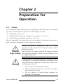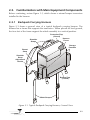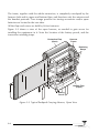
1
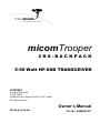
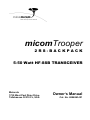
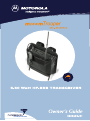
COMMERCIAL WARRANTY (STANDARD)
Motorola radio communications products are warranted to be free from defects in material
and workmanship for a period of ONE (1) YEAR, (except for crystals and channel elements
which are warranted for a period of ten (10) years) from the date of shipment. Parts,
including crystals and channel elements, will be replaced free of charge for the full
warranty period but the labor to replace detective parts will only be provided for One
Hundred-Twenty (120) days from the date of shipment. Thereafter purchaser must pay for
the labor involved in repairing the product or replacing the parts at the prevailing rates
together with any transportation charges to or from the place where warranty service is
provided. This express warranty is extended by Motorola Communications and Electronics
Inc., 1301 E. Algonquin Road, Schaumburg, Illinois 60196, to the original purchaser only,
and only to those purchasing for purpose of leasing or solely for commercial, industrial, or
governmental use.
THIS WARRANTY IS GIVEN IN LIEU OF ALL OTHER WARRANTIES EXPRESS OR
IMPLIED WHICH ARE SPECIFICALLY EXCLUDED, INCLUDING WARRANTIES OF
MERCHANTABILITY OR FITNESS FOR A PARTICULAR PURPOSE. IN NO EVENT SHALL
MOTOROLA BE LIABLE FOR INCIDENTAL OR CONSEQUENTIAL DAMAGES TO THE
FULL EXTENT SUCH MAY BE DISCLAIMED BY LAW.
In the event of a defect, malfunction or failure to conform to specifications established by
Seller, or if appropriate, to specifications accepted by Seller in writing, during the period
shown. Motorola, at its option, will either repair or replace the product or refund the
purchase price thereof, and such action on the part of Motorola shall be the full extent of
Motorola's liability hereunder.
This warranty is void if:
a. The product is used in other than its normal and customary manner.
b. The product has been subject to misuse, accident, neglect or damage.
c. Unauthorized alterations or repairs have been made, or unapproved parts used in
the equipment.
This warranty extends only to individual products, batteries are excluded, but carry their
own separate limited warranty. Because each radio system is unique, Motorola disclaims
liability for range, coverage, or operation of the system as a whole under this warranty
except by a separate written agreement signed by an officer of Motorola.
Non-Motorola manufactured products are excluded from this warranty, but subject to the
warranty provided by their manufacturers, a copy of which will be supplied to you on
specific written request.
In order to obtain performance of this warranty, purchaser must contact its Motorola
salesperson or Motorola at the address first above shown, attention Quality Assurance
Department.
This warranty applies only within the United States.
COMPUTER SOFTWARE COPYRIGHTS
The Motorola products described in this instruction manual may include copyrighted
Motorola computer programs stored in semiconductor memories or other media. Laws in
the United States and other countries preserve for Motorola certain exclusive rights for
copyrighted computer programs, including the exclusive right to copy or reproduce in any
form the copyrighted computer program. Accordingly, any copyrighted Motorola
computer programs contained in the Motorola products described in this instruction
manual may not be copied or reproduced in any manner without the express written
permission of Motorola. Furthermore, the purchase of Motorola products shall not be
deemed to grant either directly or by implication, estoppel, or otherwise, any license
under the copyrights, patents or patent applications of Motorola, except for the normal
non-exclusive, royalty free license to use that arises by operation of law in the sale of a
product.
micomTrooper
2RS-BACKPACK
5-50 Watt HF-SSB TRANSCEIVER
© MOBAT
3 Israeli Shimon St.
P.O.B. 5090
Industrial Zone, Rishon le’Zion 75151, Israel
All rights reserved
Owner’s Manual
Printed in Israel
Cat. No. 6886863J01
micomTrooper
2RS-BACKPACK
5-50 Watt HF-SSB TRANSCEIVER
Motorola
1720 West Paul Dirac Drive,
Tallahassee 32310 FL, USA
Owner’s Manual
Cat. No. 6886863J01
WARNINGS, CAUTIONS AND NOTES
The following notations are used to place special emphasis on procedures, or to call
attention to precautionary measures.
Warning
An operating procedure, practice and so forth, which if not
followed correctly, could result in personal injury, or loss of
life.
Caution An operating procedure, practice and so forth, which if not
followed correctly, could result in damage to, or destruction of
equipment.
Note An operating procedure, condition and so forth, to which special
attention should be paid.
General Safety Precautions
The following are general safety precautions that are not related to any specific procedures
and therefore do not appear elsewhere in this publication. These are recommended
precautions that personnel must understand and apply, in addition to the precautions
listed in the Information for Safe, Efficient Operation section.
Do not touch the antenna and the RF connectors when the
transceiver operates.
Warning
High
Voltage
During transmission, high RF voltages appear at the RF
connectors, the antenna cables, and on the antenna itself.
These voltages may cause severe injury or even death on
contact.
Operating and maintenance personnel must be familiar with
the applicable safety requirements before attempting to install
or operate the transceiver. Severe injury or death could result
from failure to comply with the safety practices.
Information for Safe, Efficient Operation
Product Safety and RF Exposure for Mobile TwoWay Radios Installed in Vehicles or as Fixed Site
Control Stations
Caution
BEFORE USING THIS RADIO, READ THIS BOOKLET WHICH
CONTAINS IMPORTANT OPERATING INSTRUCTIONS FOR
SAFE USAGE AND RF ENERGY AWARENESS AND CONTROL
INFORMATION FOR COMPLIANCE WITH RF ENERGY
EXPOSURE LIMITS IN APPLICABLE NATIONAL AND
INTERNATIONAL STANDARDS.
The information provided in this document supersedes the general safety information
contained in user guides published prior to February 2002.
Compliance with RF Energy Exposure Standards
NOTICE
This radio is intended for use in occupational/controlled
applications where users have been made aware of the
potentional for exposure and can exercise control over their
exposure. This radio device is NOT authorized for general
population, consumer or similar use.
Motorola, Inc. 2003
8000 W. Sunrise Blvd., Ft. Lauderdale, FL 33322
Printed in USA. 7/03
Federal Communication Commission Regulations
The FCC has established limits for safe exposure to radio frequency (RF) emissions
from mobile two-way radios. The FCC requires manufacturers to demonstrate
compliance with RF exposure limits before mobile two-way radios can be marketed In
the U.S. When two-way radios are approved for occupational/controlled environment
exposure limits, the FCC requires users to be fully aware of, and exercise control over,
their exposure. Awareness and control of RF exposure can be accomplished by
education or training through appropriate means such as information and instructions
in user manuals or safety booklets, or other appropriate means. This user safety
booklet includes useful information about RF exposure and helpful instructions on
how to control your RF exposure.
Your Motorola two-way radio is designed and tested to comply with a number of national
and international standards and guidelines (listed below) regarding human exposure to
radio frequency electromagnetic energy. This radio complies with the IEEE (FCC) and
ICNIRP exposure limits for occupational/controlled RF exposure environments at
usage factors of up to 50% talk-50% listen. In terms of measuring RF energy for
compliance with FCC exposure guidelines, your radio radiates measurable RF energy
only while it is transmitting (during talking), not when it is receiving (listening) or in
standby mode.
Your Motorola two-way radio complies with the following RF energy exposure
standards and guidelines:
•
United States Federal Communications Commission, Code of Federal Regulations;
47CFR part 2 sub-part J
•
American National Standards Institute (ANSI) / Institute of Electrical and Electronic
Engineers (IEEE) C95.1-1992
•
Institute of Electrical and Electronic Engineers (IEEE) C95.1-1999 Edition
•
International Commission on Non-Ionizing Radiation Protection (ICNIRP) 1998
•
Ministry of Health (Canada) Safety Code 6: Limits of Human Exposure to
Radiofrequency Electromagnetic Fields in the Frequency Range from 3 kHz to 300
GHz, 1999
•
Australian Communications Authority Radiocommunications (Electromagnetic
Radiation – Human Exposure) Standard, 2001
•
ANATEL, Brasil Regulatory Authority, Resolution 256 (April 11, 2001: Additional
Requirements for SMR, Cellular and PCS Product Certification.
Compliance and Control Guidelines and Operating Instructions
for Mobile Two-Way Radios Installed in Vehicles
To control your exposure and ensure compliance with the occupational/ controlled
environment exposure limits, always adhere to the following procedures:
•
To transmit (talk), push the Push-To-Talk (PTT) button; to receive, release the
PTT button. Transmit only when people outside the vehicle are at least the
minimum lateral distance away (as shown in table below) from a properly
installed, externally-mounted antenna.
The table below lists the minimum lateral distance for bystanders in an
uncontrolled environment from the transmitting antenna at several different ranges
of rated radio power for mobile radios installed in a vehicle.
•
Rated Power of Vehicle-Installed
Mobile Two-Way Radio
Minimum Lateral Distance from
Transmitting Antenna
Less than 7 watts
8 inches (20 centimeters)
7 to 15 watts
1 foot (30 centimeters)
16 to 50 watts
2 feet (60 centimeters)
51 to 110 watts
3 feet (90 centimeters)
Install mobile antennas at the center of the roof or the center of the trunk deck
per specific guidelines and instructions in the Radio Installation Manual. These
mobile antenna installation guidelines are limited to metal body vehicles.
Use only the Motorola-approved, supplied antenna or a Motorola- approved
replacement antenna. Use of non-Motorola-approved antennas, modifications, or
attachments could damage the radio and may violate FCC regulations.
•
For a list of Motorola-approved antennas, visit the following web site:
http://www.motorola.com/cqiss/index.shtml.
For additional information on exposure requirements or other training information,
visit http://www.motorola.com/rfhealth.
Compliance and Control Guidelines and Operating Instructions for
Mobile Two-Way Radios Installed as Fixed Site Control Stations
If mobile radio equipment is installed at a fixed location and operated as a control station
or as a fixed unit, the antenna installation must comply with the following requirements in
order to ensure optimal performance and compliance with the RF energy exposure limits
in the standards and guidelines listed in the Federal Communication Commission
Regulations section.
•
The antenna should be mounted outside the building on the roof or a tower if at all
possible.
•
As with all fixed site antenna installations, it is the responsibility of the licensee to
manage the site in accordance with applicable regulatory requirements and may
require additional compliance actions such as site survey measurements, signage, and
site access restrictions in order to ensure that exposure limits are not exceeded.
Electromagnetic Interference/Compatibility
Note Nearly every electronic device is susceptible to electromagnetic
interference (EMI) if inadequately shielded, designed, or otherwise
configured for electromagnetic compatibility. It may be necessary to
conduct compatibility testing to determine if any electronic equipment
used in or around vehicles or near fixed site antenna is sensitive to
external RF energy or if any procedures need to be followed to
eliminate or mitigate the potential for interaction between the radio
transmitter and the equipment or device.
Facilities
To avoid electromagnetic interference and/or compatibility conflicts, turn off your radio
In any facility where posted notices instruct you to do so. Hospitals or health care
facilities may be using equipment that is sensitive to external RF energy.
Vehicles
To avoid possible interaction between the radio transmitter and any vehicle electronic
control modules, for example, ABS, engine, or transmission controls, the radio should be
installed only by an experienced installer and that the following precautions be used when
installing the radio:
1.
Refer to the manufacturer's instructions or other technical bulletins for
recommendations on radio installation.
2.
Before installing the radio, determine the location of the electronic control
modules and their harnesses in the vehicle.
3.
Route all radio wiring, including the antenna transmission line, as far away as
possible from the electronic control units and associated wiring.
Driver Safety
Check the laws and regulations on the use of radios in the area where you drive. Always
obey them.
When using your radio while driving, please:
•
Give full attention to driving and to the road.
•
Pull off the road and park before making or answering a call if driving conditions so
require.
Operational Warnings
For Vehicles with an Air Bag
Warning
Do not mount or place a mobile radio in the area over an air bag
deployment area. Air bags inflate with great force. If a radio Is
placed in the air bag deployment area and the air bag inflates,
the radio may be propelled with great force and cause serious
injury to occupants of the vehicle.
Potentially Explosive Atmospheres
Turn off your radio prior to entering any area with a potentially
explosive atmosphere. Sparks in a potentially explosive
atmosphere can cause an explosion or fire resulting in bodily
injury or even death.
The areas with potentially explosive atmospheres include fueling
areas such as below decks on boats, fuel or chemical transfer or
storage facilities, and areas where the air contains chemicals or
particles such as grain, dust or metal powders. Areas with
potentially explosive atmospheres are often, but not always,
posted.
Blasting Caps and Blasting Areas
Warning
To avoid possible interference with blasting operations, turn off
warning your radio when you are near electrical blasting caps, in
a blasting area, or in areas posted: "Turn off two-way radio".
Obey all signs and instructions.
For radios installed in vehicles fueled by liquefied petroleum gas,
refer to the (U.S.) National Fire Protection Association standard,
NFPA 58, for storage, handling, and/or container information. For
a copy of the LP-gas standard, NFPA 58, contact the National Fire
Protection Association, One Battery Park, Quincy, MA.
Table of Contents
Page
Chapter 1
Introduction.......................................................................... 1-1
1-1. Scope ......................................................................................... 1-1
1-2. Purpose and Use......................................................................... 1-2
1-3. Equipment Description................................................................ 1-4
1-3.1
Functional Description ................................................... 1-4
1-3.2
Main Operational Features ............................................. 1-4
1-4. Main Technical Specifications...................................................... 1-7
Chapter 2
Preparation for Operation .................................................... 2-1
2-1. Scope ......................................................................................... 2-1
2-2. Unpacking and Inspection........................................................... 2-2
2-3. Familiarization with Main Equipment Components ......................... 2-3
2-3.1
Backpack Carrying Harness ............................................ 2-3
2-3.2
micomTrooper Transceiver ............................................. 2-5
2-4. Preparing for Backpack Operation............................................... 2-6
2-4.1
Outline of Preparation Procedures.................................. 2-6
2-4.2
Installation of micomTrooper Battery .............................. 2-6
2-4.3
Installation of Transceiver in Carrying Harness................. 2-8
2-4.4
Installation of Whip Antenna .......................................... 2-12
2-4.5
Connection of Audio Accessories.................................... 2-14
2-4.6
Wearing the Backpack Carrying Harness......................... 2-14
Chapter 3
Operation ............................................................................. 3-1
3-1. Scope ......................................................................................... 3-1
3-2. Channel Mode Menu .................................................................. 3-2
3-3. Menu Functions .......................................................................... 3-3
Cat. No. 6886863J01
i
Table of Contents (Cont'd)
Page
Appendix A Static Operation.................................................................... A-1
A-1. Scope ......................................................................................... A-1
A-2. Procedure ................................................................................... A-1
Appendix B Using Battery Charger, FLN9541 .......................................... B-1
B-1. Purpose and Use......................................................................... B-1
B-2. Operating Instructions ................................................................. B-2
B-3. Main Technical Specifications...................................................... B-3
ii
LIST OF ILLUSTRATIONS
Page
Figure 1-1.
micomTrooper Ready for Operation, General View ................... 1-3
Figure 2-1.
Typical Backpack Carrying Harness, General View..................... 2-3
Figure 2-2.
Typical Backpack Carrying Harness, Open View ........................ 2-4
Figure 2-3.
micomTrooper Transceiver, General View ................................. 2-5
Figure 3-1.
Channel Mode Menu................................................................ 3-2
Figure 3-2.
Menu Functions (Page 1 of 3))................................................... 3-3
Figure 3-3.
Menu Functions (Page 2 of 3).................................................... 3-4
Figure 3-4.
Menu Functions (Page 3 of 3).................................................... 3-5
Figure A-1.
Connecting the Dipole or Long-Wire Antenna ...........................A-3
iii
Intentionally Left Blank
iv
Chapter 1
Introduction
1-1. Scope
This manual provides operating instructions for the micomTrooper, a highfrequency (HF) single sideband (SSB) backpack transceiver. The manual is
organized as follows:
Chapter 1 –
General Description: provides a general description of the
micomTrooper backpack transceiver and presents its main
technical characteristics.
Chapter 2 –
Preparation for Operation: provides instructions for preparing a
micomTrooper transceiver for backpack operation.
Chapter 3 –
Operating Instructions: presents concise operating instructions
for the micomTrooper transceiver.
Appendix A – Static Operation: provides instructions for preparing the
micomTrooper for static operation using a dipole or long-wire
antenna.
Appendix B – Using Battery Charger FLN9541: provides instructions for using
the FLN9541 for recharging the Lithium ion battery used by
micomTrooper transceivers.
micomTrooper is part of the MICOM family of HF-SSB radio sets; it has
compatible characteristics and uses the same operating procedures as other
MICOM transceivers. Therefore, this manual is intended for use with the
following manuals:
•
"MICOM-2E/2R ALE HF-SSB Transceiver Owner’s Guide", Publication
68P02952C60-A, which presents the common operating procedures
•
"MICOM-2ES/2RS/2TS ALE HF-SSB Transceiver” Supplement 68MB000010
to the Owner’s Guide 68P02952C60-A, which presents additional
capabilities and operating procedures.
Cat. No. 6886863J01
1-1
1-2. Purpose and Use
micomTrooper (MICOM-2RS) transceiver is a backpack version of the robust
MICOM-2R mobile radio. For backpack operation, micomTrooper is powered by
a lightweight Lithium ion rechargeable battery, has selectable power output of 5
to 20 W and high sensitivity, and uses a foldable whip antenna matched by a
built-in automatic antenna tuner unit. When necessary, micomTrooper can be
programmed to reach a power output of 50 W, and can also be used with dipole,
long-wire and many other types of broadband antennas for static operation.
These capabilities provide reliable long-range HF-SSB radio communications in a
rugged yet lightweight backpack configuration. Designed to meet the needs of
users who carry out on-foot operations in remote areas, it is built to withstand
years of shock and vibration as well as severe weather conditions. micomTrooper
is certified for dependability and durability, and complies with US standard MILSTD-810F.
The micomTrooper is equipped with a military-type handset, whip antenna,
cables and connectors, delivering superior quality in a radio priced to fit the
needs of a wide range of organizations. For backpack operations, the
micomTrooper is carried in a convenient, lightweight harness that completely
envelops the transceiver.
The durable aluminum frame of the harness protects against damage and allows
placing the transceiver on ground for static operations.
Figure 1-1 shows a general view of a micomTrooper ready for backpack
operation, as seen when the harness protection flap is opened.
1-2
Whip Antenna
micomTrooper
Transceiver
Antenna
Base
Backpack Carrying
Harness
Handset
Figure 1-1. micomTrooper Ready for Operation, General View
1-3
1-3. Equipment Description
1-3.1
Functional Description
The micomTrooper is an advanced and flexible backpack-portable HF-SSB
transceiver that provides a complete solution to the communication requirements
in the crowded HF band. micomTrooper has an automatic antenna tuner, which
supports a wide range of antennas, including a light-weight foldable whip for
portable (backpack) operation; dipole, long wire, and many other types of
antennas can be used for static operation.
The micomTrooper provides voice, data, and telegraphy (CW) communication.
Communication reliability and quality is improved by means of automatic
frequency management and automatic link establishment (ALE). In addition, the
ALE function also provides Automatic Message Display (AMD), that enables
operators to exchange preprogrammed messages while establishing a link.
The transmit output power is operator-selectable (5, 10 or 20 W). When used in
a backpack configuration, the operator can reduce the transmit power and thus
increase battery life when the communication conditions do not require the
maximum transmit power (20 W).
Under bad propagation conditions or in an emergency, the operator can rapidly
switch to static operation by simply placing the self-supporting micomTrooper
harness on ground, and increase the transmit power to 50 W. Under static
operating conditions, the operator can easily connecting a dipole or another long
wire antenna instead of the whip, further increasing communication efficiency.
Using a dipole or long wire antenna also extends the lower operating frequency
from 3.0 to 1.6 MHz.
micomTrooper is powered by a 16V, 12Ah rechargeable Lithium ion battery, type
ML1416-L. Spare batteries can be carried in the backpack harness.
1-3.2
Main Operational Features
This section presents a concise list of the main operational features of the
micomTrooper transceiver.
For a description of the additional capabilities and features of MICOM
transceivers, see the "MICOM-2E/2R ALE HF-SSB Transceiver Owner’s Guide",
Publication 68P02952C60-A, and the "MICOM-2ES/2RS/2TS ALE HF-SSB
Transceiver” Supplement 68MB000010 to the Owner’s Guide 68P02952C60-A.
1-4
➤
Fast and simple radio link establishing:
Automatic Link Establishment (ALE) per MIL-STD-1045 and
MIL-STD-188-141.
Full interoperability with other manufacturers' radios complying
with the same ALE standards.
➤
Loud and clear voice communication:
Built-in voice quality system with proprietary DSP algorithms that
filter out background noises and elevates sound bytes, providing
exceptional communication clarity.
Selectable bandwidth, for fine tuning and optimal voice reception.
Unmatched combination of high power (up to 50 W) and high
sensitivity (0.5 µV) for outstanding communication coverage.
Voice-activated digital squelch.
➤
User-friendly operation:
Large alphanumeric front panel display and keyboard for
programming and set-up.
Support for multiple languages.
➤
Years of trouble-free, advanced communications.
Upgrading to future technologies is easily made by installing new
software into the transceiver's DSP unit.
Easily replaceable digital
maintenance and repair.
components
ensure
cost-effective
Very high MTBF, as with all MICOM radios.
Unique Built-In Self Test system that provides exceptional diagnostic
capability.
➤
Comprehensive communication and networking services
MultiNet enables integration of different HF radio networks into
one seamless network, allowing excellent coordination between
different units and forces.
AMD for transmission and reception of pre-set text messages.
Optional GPS embedded application.
1-5
➤
Part of a proven family of radio products:
micomTrooper is a member of the family of MICOM radio
transceivers for fixed base stations, mobile vehicle-mounted and
hand-carried units serving the long-range wireless communication
needs of hundreds of organizations worldwide.
➤
Main optional accessories:
Secure voice
AC battery charger, FLN9541
External GPS
Spare 12Ah rechargeable Lithium ion battery.
1-6
1-4. Main Technical Specifications
Specifications
Frequency Range
With Whip Antenna
3.0 to 30 MHz
With Dipole or Long Wire 1.6 to 30 MHz
Dimensions
Options
Number of Preset Channels
200
Transmit Power
5, 10, 20, 50 W
Receive Frequency Range
100 kHz – 30 MHz Rx
Sensitivity
SSB: 0.5 µV for 10 dB SINAD
Audio Bandwidth
350 to 2700 Hz
Frequency Stability
0.6 ppm
Frequency Resolution
10 Hz
Operating Temperature
Range
-124 to +184°F (-30 to +60°C)
Operating Voltage
12V nominal
Height
17.7 inch (450 mm)
Width
13 inch (330 mm)
Depth
5.1 inch (130 mm)
Weight
16 lbs (7.1 kg)
RS-232 Remote Control Interface
RSS for PC (Radio and ALE)
Multinet Operation (for ALE)
1-7
Intentionally Left Blank
1-8
Chapter 2
Preparation for
Operation
2-1. Scope
This Chapter provides instructions for preparing the micomTrooper for backpack
operation. The information presented in this Chapter includes:
•
Unpacking – para. 2-2
•
Familiarization with main equipment components − para. 2-3
•
Preparation for backpack operation – para. 2-4.
Refer to Appendix A for instructions on how to adapt the backpack transceiver to
static operation with dipole or other long-wire antennas.
During transmission, dangerously high RF voltages
appear at the RF connectors, the antenna cables, and on
the antenna itself.
Warning
Do not touch the antenna and the RF connectors when
High Voltage the transceiver operates. Make sure the antenna is not
near high-voltage lines.
Warning
Lithium batteries contain dangerous chemicals. Handle
and dispose of used Lithium batteries according to the
prescribed safety regulations. In particular, observe the
following precautions:
1. Do not short-circuit Lithium batteries.
2. Do not damage battery case and do not tamper
with battery in any way.
3. Do not dispose of used Lithium batteries by
burning or incinerating.
Cat. No. 6886863J01
2-1
2-2. Unpacking and Inspection
a.
A preliminary inspection of the equipment containers should be made
prior to unpacking. Evidence of damage should be noted and reported
immediately to the proper authorities. Unpack the equipment as follows:
(1)
Place each container on a clean flat surface, cut all straps, and open
or remove the top.
(2)
Take out each item carefully and place it securely on a clean surface.
(3)
Remove the packing material while looking for small items.
(4)
Fold and store the containers and packing materials for use.
b. Checking Unpacked Equipment.
2-2
(1)
Inspect all items for damage.
found.
Immediately report any damage
(2)
Check all items against the items listed in the accompanying
packing slip. Report any missing items or discrepancies.
2-3. Familiarization with Main Equipment Components
Before continuing, review Figure 1-1, which shows a micomTrooper transceiver
installed in the harness.
2-3.1
Backpack Carrying Harness
Figure 2-1 shows a general view of a typical backpack carrying harness. The
harness has a frame that supports the transceiver. When placed on level ground,
the four feet of the frame support the whole assembly in a vertical position.
Shoulder
Straps
Protection Flap
(Closed)
Harness
Frame
Storage
Pouches
Breast
Strap
Shoulder
Strap
Adjustment
Buckle
Bottom Flap
(Closed)
Waist Straps
Figure 2-1. Typical Backpack Carrying Harness, General View
2-3
The frame, together with the whole transceiver, is completely enveloped by the
harness cloth and its upper and bottom flaps, and therefore only the antenna and
the handset protrude. Two storage pouches for storing accessories and/or spare
batteries are located to the two sides.
All the flaps and covers are held by Velcro fasteners.
Figure 2-2 shows a view of the open harness, as needed to gain access for
installing the equipment in it. Note the location of the battery pouch, and the
transceiver retaining straps.
Protection Flap
(Open)
Harness
Frame
Retaining
Straps
Bottom Flap
(Open)
Battery
Pouch
Figure 2-2. Typical Backpack Carrying Harness, Open View
2-4
2-3.2
micomTrooper Transceiver
Figure 2-3 shows a general view of the micomTrooper transceiver, and its
connectors. Note the coaxial cable connecting the transceiver to the automatic
antenna tuner (ATU).
micomTrooper
Transceiver
Automatic Antenna
Tuner (ATU)
Whip Mount
ATU RF Connector
Transceiver
RF Connector
Coaxial Cable
Power
Connector
Figure 2-3. micomTrooper Transceiver, General View
2-5
2-4. Preparing for Backpack Operation
2-4.1
Outline of Preparation Procedures
The preparation of a micomTrooper transceiver for operation includes:
1. Installation of battery in carrying harness.
2. Installation of transceiver in carrying harness.
3. Installation of antenna and audio accessories.
4. When ready to go − wearing the backpack carrying harness.
2-4.2
Installation of micomTrooper Battery
1. Place the carrying harness on a clean, flat surface.
2. Release the two battery flaps, and then release the two straps holding the
battery (all these items have Velcro fasteners).
3. Remove old battery, if any.
4. Visually check battery and battery pouch for dirt or damage. Clean if
necessary.
5. Orient the battery as shown in figure, and push the battery in place.
6. Reattach the two straps holding the battery, and then close the battery
pouch with its flaps (first the bottom flap, and then attach the upper flap).
2-6
Upper Battery
Flap
Battery Straps
Lower Battery
Flap
2-7
2-4.3
Installation of Transceiver in Carrying Harness
1. Place the carrying harness on a level surface, with the metal braces facing
upward.
2-8
2.
Place the micomTrooper on the top of the carrying harness, with its front
panel upwards and its rear resting on the carrying harness (see figure).
Note position of audio connectors: they must be to the left.
3.
Connect the three-pin D-type power connector of the power cable to the
micomTrooper power connector. Fasten securely the two connector
screws.
4.
Connect the other connector of the power cable to the battery connector.
Fasten securely the connector screw.
Transceiver
Power
Connector
Power
Cable
Battery
Connector
2-9
5. Push the transceiver down, toward the battery, until it is stopped by the
aluminum frame.
6. Fasten the transceiver to the carrying harness with the two retaining
straps.
7. Close the harness around the transceiver as shown in the figure on the
next page (the Velcro fasteners will keep it in position).
2-10
2-11
2-4.4
Installation of Whip Antenna
1. Visually inspect the whip mount connector (located on the ATU) for dirt
or damage. Clean if necessary.
2. Screw antenna base AB-591 into the whip mount connector. Tighten by
hand only.
3. Extend the whip: this is done by carefully whipping it outwards. Secure all
sections by inserting them one into the other by hand.
4. Screw whip antenna sections into antenna base.
5. To remove the whip antenna, perform the above tasks in the reverse
order.
CAUTION
When folding the whip, always start with the upper section,
otherwise it may be damaged.
2-12
Whip Antenna
Antenna
Base
Whip
Mount
Handset
2-13
2-4.5
Connection of Audio Accessories
1. Connect the handset, H-250, to either of the two audio connectors on
the front panel of the micomTrooper.
2. If necessary, connect an additional audio accessory, for example,
telegraphy key or headset, to the other audio connector.
2-4.6
Wearing the Backpack Carrying Harness
To wear the backpack:
•
Put harness on your back by inserting arms through shoulder straps.
•
Tighten shoulder straps.
•
Buckle waist straps to belt and adjust to size.
•
Adjust the breast strap length and then attach the strap.
At this stage, the micomTrooper is ready for use as a backpack radio set.
2-14
Shoulder
Straps
Protection Flap
(Closed)
Breast
Strap
Shoulder
Strap
Adjustment
Buckle
Bottom Flap
(Closed)
Waist
Strap
2-15
Intentionally Left Blank
2-16
Chapter 3
Operation
3-1. Scope
This Chapter presents concise operating instructions for the micomTrooper
transceiver.
The information appearing in this Chapter assumes that you are familiar with the
operation of the MICOM family of HF-SSB transceivers, and in particular with the
operating instructions presented in the following manuals:
•
"MICOM-2E/2R ALE HF-SSB Transceiver Owner’s Guide", Publication
68P02952C60-A, which presents common operating procedures for
MICOM transceivers
•
"MICOM-2ES/2RS/2TS ALE HF-SSB Transceiver” Supplement 68MB000010 to
the Owner’s Guide 68P02952C60-A, which presents additional capabilities
and operating procedures.
Therefore, the Chapter presents only the menu structure of the micomTrooper
transceiver.
Cat. No. 6886863J01
3-1
3-2. Channel Mode Menu
Figure 3-1 shows the micomTrooper channel mode menu.
CH
F
2,000.000
BAND SQ
DSP™
MORE
SQ
BAND
DSP
ON
OFF
LSB
USB
CLAR
NF
CLIP
NB
ATTN
ON
OFF
ON
OFF
ON
OFF
MORE
MORE
PWR
MODE
LOW
MED
HIGH
MAX
MORE
SSB
AME
PLT
AGC
OFF
SLOW
FAST
MORE
RCLV
CALL
..
.
..
ALL CALL
NET 1
..
..
.
NET 20
MON
ON
OFF
Figure 3-1. Channel Mode Menu
3-2
BW
2.1
2.7
3.0
3.3
LSM
CW
3-3. Menu Functions
Figure 3-2, Figure 3-3 and Figure 3-4 show the menu functions, reached after
pressing the MENU button.
MENU
CHAN FREQ ALE
BIT™
MORE
CHAN
FREQ
1
2
3
4
ALE
SMPX
DPLX
RXO
TXO
NET
BIT
FULL
CHAN
RF
ENTER
NO
MORE
LOCK
PROG
PSW
LOCK
PSW
PSW
OLD
RAD
See Figure 3-3
ALE
See Figure 3-4
LANG
DIM
LEVEL
0123
FRNC
SPAN
BAH
Figure 3-2. Menu Functions (Page 1 of 3))
Note
When using the micomTrooper with its whip antenna,
make sure to select YES for the TUNER option
(MENU>MORE>PROG>RAD>OPTS – see Figure 3-3).
When using the micomTrooper with a dipole or long
wire antenna (static operation as described in Appendix
A), make sure to select NO for the TUNER option.
3-3
MENU
LOCK PROG PSW
DIM™
RAD
ALE
LANG
See Figure 3-4
See Figure 3-2
OPTS
PRMT
CHAN
TUNE
ACC
YES
NO
MORE
BAUD
DPWR
MST
AST
STOR
ERAS
PTBP
PWR
AMP
ACC1
ACC2
NON
KBBP
TONE
FREQ
ADT
ATTN
MORE
BAND
MODE
AGC
BW
Figure 3-3. Menu Functions (Page 2 of 3)
3-4
YES
NO
MORE
MORE
GET
ALE
CW
RCLV
DIM
MENU
LOCK PROG PSW
DIM™
RAD
LANG
ALE
See Figure 3-3
See Figure 3-2
MORE
DIR
NET
OPT
AMD
AUTO
STOR
ADDR
AMD
ADD
ERAS
EDIT
YES
NO
ERAS
YES
NO
MORE
MORE
PTOT
..
..
.
EXAL
ALRT
YES
NO
YES
NO
1
..
..
.
10
TOT
MLQA
YES
NO
..
..
.
0
..
..
.
100
QCAL
AADR
YES
NO
YES
NO
MxCH
..
..
.
0
..
..
.
59
MORE
NAME
MEMB
CHAN
OPT
GET
ERAS
YES
NO
MORE
MORE
NET
SELF
HACK
SOND
ADD
ERAS
SLNT
SORT
MACK
OCUP
LQAR
ADD
ERAS
ALLC
SCN
ALLC
M/S
TUNE
Figure 3-4. Menu Functions (Page 3 of 3)
3-5
Intentionally Left Blank
3-6
Appendix A
Static Operation
A-1. Scope
This Appendix provides instructions for preparing the micomTrooper for static
operation using a dipole or long-wire antenna.
A-2. Procedure
When using a micomTrooper transceiver with a dipole or long-wire antenna, the
antenna must be directly connected to the transceiver RF connector. Therefore, it
is necessary to disconnect the connection between the transceiver and ATU.
In the following procedure, refer to Figure A-1.
Cat. No. 6886863J01
A-1
➤
To connect a dipole or long-wire antenna:
1. Turn the transceiver off.
2. Open the harness envelope, to reach the coaxial cable
interconnecting the RF connectors of the transceiver and the ATU.
3. Disconnect the cable from the transceiver RF connector.
4. Connect the coaxial feed of the antenna directly to the transceiver RF
connector.
5. You may now disassemble the whip antenna (see Chapter 2).
6. Close the harness envelope. You may now operate the transceiver
with the dipole or long-wire antenna.
➤
A-2
To return the transceiver to regular operation (with whip
antenna):
Reconnect the ATU to the transceiver and reinstall the whip antenna
by reversing the procedure given above.
2. Connect Coaxial
Feed Connector
1. Disconnect Cable
from ATU
Coaxial Feed
to Dipole or
Long Wire
Antenna
Figure A-1. Connecting the Dipole or Long-Wire Antenna
A-3
Intentionally Left Blank
A-4
Appendix B
Using Battery
Charger, FLN9541
B-1. Purpose and Use
FLN9541 is an AC-powered battery charger designed to charge 16V, 12Ah Lithium
ion rechargeable batteries of the type used by micomTrooper (ML1416-L).
FLN9541 is simple to operate and does not require operator attendance during
operation. Yet it provides advanced features, such as fully automatic charging and
automatic turn-off after battery charging is completed. Three indicators display
the operating state, and sounds are used to signal proper connection of battery,
end of charge, etc.
FLN9541 has only two controls:
•
POWER on/off switch. When the FLN9541 is turned on, a green indicator,
UDC, lights to indicate that the charger is OK.
•
CHARGE pushbutton (red): after connecting the battery to be charged, press
the pushbutton to start charging. While charging, a yellow CHARGE
indicator lights. The end of charge is indicated by the flashing of a green
FINISH CHARGE indicator.
The battery charger is a compact unit, intended for use in rooms, shelters, etc. Do
not expose the battery charger to direct sun radiation or excessive temperatures,
rain, snow, or high humidity. Keep charger battery contacts clean and avoid
accidental short-circuits by turning the charger on only after a battery is installed
on the charger.
Cat. No. 6886863J01
B-1
B-2. Operating Instructions
1.
Place the battery charger on a flat surface, protected from sun and
rain.
2.
Insert the charger power cable plug into an AC outlet.
3.
Connect the battery to be charged to the battery charger: place the
battery socket over the charger pins and press firmly to mate (the
connectors will mate only if battery is placed with the correct
orientation). Beeps must be heard, to indicate proper contact with
the charger.
Note
Beeps must be heard, to indicate proper contact with
the charger.
If no beeps are heard, remove and then reconnect the
battery. Also check that the charger pins are clean. If no
beeps are heard after the battery is reconnected, the
battery is probably bad and cannot be recharged.
4.
5.
Turn the charger on by setting its front panel POWER switch to
ON:
•
The green UDC indicator will light
•
The green FINISH CHARGE starts flashing, and a tone is heard.
Start the charging by pressing the red CHARGE pushbutton. The
yellow CHARGE indicator will turn on and the tone stops.
Note
6.
The charger now operates automatically.
Note
B-2
If the battery is faulty or makes bad contact with the
battery charger, the CHARGE indicator will not turn on
after pressing the CHARGE pushbutton, and no charge
current is supplied to the battery.
If a power source failure occurs while the battery is being
charged, the FINISH CHARGE starts flashing, and an
alarm tone is heard. To resume charging after power
returns, press again the red CHARGE pushbutton.
7.
You will be notified when the battery is fully charged: the FINISH
CHARGE indicator will start flashing and the tone is heard again.
8.
At this stage, set the POWER switch to OFF, and remove the battery
from the charger.
9.
Disconnect the charger power cable from the AC outlet.
B-3. Main Technical Specifications
Input voltage
90 to 265 VAC, 20 to 60 Hz
Charged battery voltage
16.8 ±0.2 V
Charging current
3.6 A
Dimensions
220 × 165 × 50 mm
Weight
1.25 kg
Environmental service conditions
Temperature
Humidity
B-3
Intentionally Left Blank
B-4