1
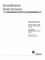
Installation
Instructions
Built-In Dishwashers
ZBD6400,ZBD6500,ZBD6600
ZBD6700,ZBD6900,ZBD7000,
ZBD7100
Chef's Washers
ZBD6605,ZBD6905,ZBD7005,
ZBD7105
Design Guide with
Installation Instructions
Monogram:
We bring good things to life.
Safety Information
BEFORE YOU BEGIN
• IMPORTANT
be installed
Read these instructions
completely
• IMPORTANT
mid carefully.
Skill Level
basic
is the
failure
due
under
the
and
responsibility
to improper
• Completion
tions require
tions.
of this
electrical
instruc-
dishwasher
skills,
of the
GE Applimace
these
- Keep these instructions
tot flltm'e reterence.
- Installation
mechanical
tion
fl'om
the
is required,
If you receixed
a damaged
immediatelv
contact
wmr
all governing
• Note
to Installer
- Be sm'e to leave
tions with the Consmner.
•
if serxice
removal
S_,,etheseinstructions
for
local inspector's
use. Observe
codes and ordinances,
• Note
to Consumer
your Owner's
Mamml
enclosm'e
- Thedishwasher
MUST
to allow for futm'e
Proper
installer,
installation
should
READ CAREFULLY.
KEEP THESE INSTRUCTIONS.
with
requires
FOR YOUR SAFETY
installa-
Read
and observe
shown
throughout
Product
is not
dislmasher,
you
dealer
or builder.
covered
Warranty.
Time
- 1 to 2 Hours. Nex_ installamore time than replacement
installa-
all CAUTION
these
and WARNINGS
instructions.
For Monogram
1-800-444-1845.
local service
in your area,
For Monogram
1-888-880-3030
service
For Monogram
1-800-626-2002.
Parts and Accessories,
in Cmmda
call
CONTENTS
Design Information
Product
Dimensions
.......................................................
Models Available ............................................................
Installation
3
3
Advance Plam_ing ..........................................................
Installation
Preparation
Materials Xzbu Will Need .................................................
Tools Ybu Will Need .......................................................
3
Parts
5
Supplied
Prepare
.................................................................
Dishwasher
Enclosure
.....................................
4
4
5
Drain Requirements
.......................................................
Prepare
Electrical
Wiring ...............................................
Prepare
Hot Water Line .................................................
Custom Pm_el Dimensions
Custom Panels tor ZBD6400 .........................................
6
7
8
Custom
9
Panels
fin" ZBD7000,
ZBD7005
........................
Instructions
Step l, Rem_we Packaging
...........................................
Step 2, Install Leveling Legs .......................................
Step 3, Remove Access Covers ....................................
Step 4, Install 90 ° Elbow ...............................................
Step 5, Install Power Cord ............................................
Step 6, Level Dishwasher.
.............................................
Step 7, Slide Dishwasher
into Opening
.......................
Step 8, Cmmect
_vVater Line ........................................
Step 9, Com_ect Drain Line ........................................
Step 1 0, Cmmect Electrical
.........................................
Step ] 1, Position and Level Dishwasher.
.....................
Step ] 2, Pre-Test Check List ........................................
Step ] 3, Dishwasher
Wet Test .....................................
Step 14, Secm'e Dishwasher
to Cabinet
or Cotmtertop
.......................................
Step 15, Install Toekick, Custoul Toekick ..................
Step ] 6, Install Side Trim Strips ..................................
Panel Installation
for Models
ZBD7000 and ZBD7005 ............................................
9
2
l0
10
10
]0
]1
]1
]]
11
19
19
13
13
13
14
14
14
15
Design Information
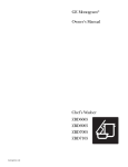
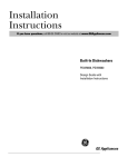
PRODUCT DIMENSIONS
ADVANCE
34"
Adjustable
to 35"
DISHWASHER
Traditional
*Dishwasher model
ZBD7000 and
Chef'sWasher
model ZBD7005
require a 3/4" thick
custom panel and
will be 24-3/4"
deep.
PLANNING
• These dishwashers
are designed
flw versatility,
adaptable
to vh'tually any installation.
• All models have a fldl length door or a modified
door to accept a fldl cabinet panel without the
traditional
access panel
• Side tub flange trim is ac!justable
and will conceal
any slight gap between
the dishwasher
and ac!jacent
cabinetry.
• These dishwashers
may be installed
beneath
cotmtertops
{)f st{me or other materials
that will not
accept screws. No trhn kit requh'ed.
Standard
installation
in 24" deep cabinets
• In standard
24" deep cabinets,
the dishwasher
door
will be flush with ac!jacent cabinetry.
• Models with 3/4" thick custom door panel will tit
flush with ac!jacent cabinetry.
MODELS
Built-In
ZBD6400
BB, Black- Accepts 1/4" or 3/4" custon_
panels
ZBD6400
WW White- Accepts 1/4" or 3/4" custoIn
panels
Trim Kits for models ZBD6400
Supplied or Custom Toekicks
• A 2-piece toekick is supplied with all models.
toekick is height
and depth a(!justable.
• Depending
on cabinetry
style, a custom toekick
also be installed
to match cabinetry.
Care must
can
be
• ZPF625W (white) or ZPF625B (black)
kits, supports
a 1/4" thick custon/door
• ZPF675W (white) or ZPF675B (black)
kits support
a 3/4" thick custom door
Traditional
Built-In
taken to assm'e door swing clearance
above the
toekick.
• A notched
continuous
toekick may be necessary
to
custmn
panel.
custom
panel.
panel
panel
allow a hmg door panel, on models
ZBD7005,
to swing back and under
The
ZBD7000 and
the dishwasher.
ZBD6500 SS, Stainless
Professional
Series
steel
ZBD6600
SS, Stainless
Fully Wrapped
ZBD6700 BB, Black
ZBD6700 W_% White
ZBD6900
SS, Stainless
Fully Integrated
Steel
ADA-Compliant
Installation
below 34" high countertops
A reduced
height installation
(32-1/2" rain.)
steel with black controls
ZBD7000
ZBD7100
custoln panel and handle
steel with tubular handle
a 34" countertop,
can be accomplished
by removing
the fl'ont leveling legs. The rear legs should be
screwed in flush with the bottom support,
as shipped.
The fl'ont of the dishwasher
illtlst be shimmed
to
level the dishwasher.
}%:ater and electrical
must be
lI, Requires
SS, Stainless
CHEF'S WASHER
Professional
MODELS
lI, Requires
SS, Stainless
routed
steel
steel
custoIn panel and handle
steel with tubular handle
through
flexibility
beneath
the back wall.
• All models are ADA-Complimm
and ZBD7005 oilier even nlore
design
Series
ZBD66{}5 SS, Stainless
Fully Wrapped
ZBD6905
SS, Stainless
Fully Integrated
ZBD7005
ZBD7105
door
because
Models ZBD7000
installation
and
the required
panel may be sized ti'om 26-1/4
See page 9 for details.
custom
to 30-1/4"
door
height.
Installation
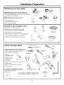
MATERIALS
Materials
Preparation
YOU WILL NEED:
Required
©G
@
for All Installations
Screw Type Clamps
[] 90° Elbow (3/8"NPT external thread on one end, opposite
90° Elbow
end sized to fit water supply)
Note: Use new ferrule. Do not use old parts.
[] Strain relief for electrical connection
[] Thread seal tape
WireNuts
StrainRelief
ThreadSeal
Tape
[] UL Listed wire connectors (3)
[] Screwtype hose clamps
Materials
©
For New Installations
Only:
[] Air gap for drain hose, if required
[] Waste tee for house plumbing, if applicable
[] Electrical cable or power cord, if applicable
[] Hand shut-off valve (recommended)
WasteTee
Shut-Off
Valve
ElectricalCable
or PowerCord
[] Water line 3/8" min. copper or 1/2" min. plastic (plastic
must be tested for temperature and pressure)
[] Couplerfor extending drain line, if applicable
Air
c°uO_pler
Gap
TOOLS YOU WILL NEED:
Tools Required
FlatBladeScrewdriver
for All Installations
[] Phillips head and flat blade screwdrivers
[] 3/8", 5/16" and 1/4" nutdrivers
[] Level
HotWater Line
_
_z_,
SafetyGlasses
_
Nut Driver
PhillipsHead
Screwdriver
,4._,_,,_
_E_
+
[] Carpenters square
[] Measuring tape
[] Safety glasses
[] Flashlight
WireStrippers
[] Bucket to catch water when flushing the line
[] Tubing cutter
[] Gloves to protect against sharp edges
[] Wire strippers
For New
Installations
Only:
[] Drill and appropriate bits
[] Hole saw set
Square
Level
Gloves
_Uubt
it_
Hole
SawSet
Installation
Preparation
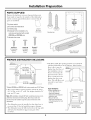
PARTS SUPPLIED:
Remove
fl'om
Check
parts
the
inside
hardware
or taped
contents
are
accessory
to the
against
bag
outside
and
other
of the
illustrations
parts
I
dishwasher.
to iilsure
that
all
Template
for
included,
I
ZBDT005
[] 2-piece toekick
[] 6 screws (see illustration)
Oily
ZBBTO00_
Junction
BoxCover
with screws
[] 2 leveling legs
[] Templatefor the installation of a
2 Leveling Legs
custom panel packed with models
'1
Template with Mounting Hardware
ZBD7000and ZBD7005only
[] Junction box cover
Screws A
Screws B
(2) Countertop
Mounting
Screws
(2) Cabinet
Mounting
Screws
Screws C
(2) Color
Matched
Toekick
Screws
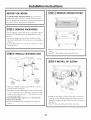
PREPARE DISHWASHER
2-PieceToekickwith
SoundInsulation
ENCLOSURE
• The
with
floor inside
the finished
floor
is tile,
the opening
floor
of the
it may
be
higher
than the floor
the installation
cutout,
34"to35"
Underside
ofCountertop
to Floor
Pieces
of wood
may
must be even and level
kitchen,
If the kitchen
of
be
placed
into the cutout
floor to make
it level or
higher
floor,
removal
service,
24-1/4"Max
than the room
This will alh)w easy
fi)r
any flmu'e
*Models ZBD7000and ZBD7005 with custom panels are 24-3/4"deep
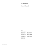
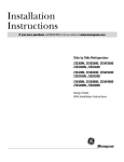
CornerInstallation
• When installing into a
corner, allow 2" rain.
clearance between
dishwasher and adjacent
cabinet or wall.
• Allow 24-1/8"min.
clearance from the front
of the dishwasher for door
opening.
• The rough cabinet opening
i/ltlSt be at least 24" deep,
23-7/8"rain,
to 24-1/4" wide. The height should be 34"
rain. and 35" max.
Note: ADA installation, beneath 34" high countertops may be accomplished by removing front leveling legs. Drain hose, water and
electrical must be routed through the cutout on the back of the
dishwasher.
• The
no
• The
dishwasher
more
than
dishwasher
and back,
enclosure,
but
must
10 feet
must
should
be installed
so that
in length
for
be flfllv
enclosed
not
support
drain
proper
any
on
part
hose
is
drainage.
the
top,
sides
of the
5
Countertop
Installation
Preparation
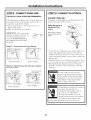
DRAIN REQUIREMENTS
Method 1 - Air Gap with Waste Tee or Disposer
An air gap must be used when the waste tee or disposer
connection is less than 18" from the floor.
• Follow local codes and ordinances.
• Do not exceed ] 0 feet distance to drain.
• To prevent
back flow into the dishwasher,
COlmect
drain line to an air gap or use a 30" high drain loop,
depending
on local codes.
• Air gap in ust be used when waste tee or disposer
COlmectioi_ is less than 18" above the floor to prevent
siphoning.
DETERMINE
DRAIN METHOD
The type ot drain iI_stallati(m
depends
(m the fl)llowing
questions.
Do local codes or ordii_ances
reqtlii'e an aii" gap?
Will waste tee or disposer
COlmectioi_ be less than 18"
above the floor?
Will installation
above the floor?
have a high
If the answer to ANYof
MUST be used.
• If all answers
these
are NO, either
drain
questions
inethod
loop less than
Method 2 - High Drain Loop with Waste Tee or
Disposer Install waste tee or disposer and air gap according
to manufacturer's instructions.
l-
30"
is YES, Method
1
inay be used.
CABINET PREPARATION
.M_ air gap MUST BE USED if the drain hose is connected to a waste tee or disposer lower than 18" above
the floor level.
• Faihu'e to provide the proper
drain COlmectioi_ using
an air gap or a 30" rain. high drain loop will result in
ilnproper
drailfing
of the dishwasher
which inav cause
damage
or poor wash peril)finance.
ll DOlT YAVOIR tree coupure ai_tirefl)ulemei_t
si le
ttlvat! de vidange est branch6
sur un raccord
d'6gout
ou
tin broyeur
d'ordures
a inoins de 46 cln (18 po) du sol.
• Si la vidange n'est pas branch_e
correctement
en
utilisant
tree coupure
ai_tirefoulelnei_t
ou tm boucle
d'_gout
d'au moins 76 Cln (30 po) de haut,
l'_coulemei_t
de l'eau du lave-vaisselle
n'est pas boil
ce q ui petit causer des dolmnages
ou tm inauvais
lavage de la vaisselle.
• Drill a 1-1/9" dia. hole in the cabinet
the shaded areas shown for the drain
tion. The
edges.
hole should
be Slnooth
wall within
hose Colmec-
with no sharp
Installation
Preparation
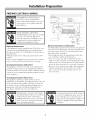
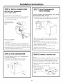
PREPARE ELECTRICAL WIRING
FOR PERSONAL
SAFETY: Remove
house fllse or open circuit breaker
before begimfing
installation.
Do not use
an extension
cord or adapter
plug with
this appliance.
POUR
ASSURER
PERSONNELLE,
LA S1_CURIT1_
ou couper le courant
axant de commencer
r
Electrical
au disjoncteur
l'installation.
cet appareil,
il ne taut pas utiliser
ralhmge
ni d'adaptateur
de prise.
de
Black
Electrical
must be supplied with 120V, 60 Hz., and
individual
properly
grounded
branch
by a 15 or 90 ampere circuit breaker
or
2 wire with ground
and rated
• If the electrical
supply does not meet
merits, call a licensed
electrician
betore
Grounding
Instructions-Cable
for 75°C
the above requireproceeding.
Direct
This appliance
must be (mmected
to a grom_ded
metal
perlnai_ei_t
wiring system, or an equipment-grounding
con ductor must be r/In with the circuit con ductors an d be
com_ected
to the equipment-grounding
on the appliance.
Grounding
Instructions-Power
2"
Axec
Requirements
• This appliance
com_ected
to an
circuit, protected
time delay fllse.
• Wiring must be
(176°F).
" Cabinet
il flint enlex er le fllsible
terminal
or lead
Connections
White
to Dishwasher:
The dishwasher
junction
box is located on the right side
at the fl'ont of the dishwasher.
The electrical
cable must
extend forward
when dishwasher
at least 24" to reach
is installed.
the junction
box
• The wiring inav enter the opening
rear or the floor within the shaded
from either
area.
side,
• Cut a 1-1/9" max. dia. hole to admit the electrical
cable or use the same hole cut tor the drain hose.
The
hole inust be flee of sharp edges. If the cabinet wall is
metal, the hole edge must be covered with a bushing.
• For power cord cmmections,
install a 3-prong grounding type receptacle
in the sink cabinet rear wall, 6"
rain, or 18" max. fl'om the opening,
and 6" to 18"
above the floor.
Cord
This appliance
Inust be gromMed.
In the event ot a
malflmction
or breakdown,
grounding
will reduce the risk
of electrical
shock by providing
a path of least resistance
fin" electric current.
The plug must be plugged
into an
appropriate
outlet that is installed and grounded
in
accordance
with all local codes and ordinances.
The improper
cmmection
of the eq uipmerit-grounding
conductor
can result in
a risk of electric shock. Check with a
qualified
electrician
or service representative if vou are in doubt that the appliance
is properly
gromMed.
I'! _ll;/'|! ai I,"I,"I
!K',
I!t'I
Le mauvais
branchement
du fil de raise h
la terre de l'&luipement
petit causer tm
choc _lectrique.
En cas de doute sin" la
raise h la terre de l'appareil,
consulter
un
_lectricien
qualifi_ ou un repr_sentant
teclmiq tie.
Installation
Preparation
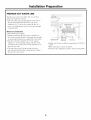
PREPARE HOT WATER LINE
The line may enter fl'om either
within the shaded area shown.
side, rear
or floor
• The water line may pass through
the same hole as
the electrical
cable and drain hose. Or, cut an
additional
l-1/2" dia. hole to admit the line. If a
power cord with plug is used,
a separate
hole.
i\
/
it must
/
i
\
\
Shut-offValve
\
pass through
,,_
ii
ii
Water
Hot[]::::
Line Connection
ii
ii
ii
• Turn o11 the water supply.
• Install a hand shut-otI valve in an accessible
loca-
tion, such as under the sink. (Optional,
but strongly
recommended
and may be required
bv local codes.)
• The hot water line should be 3/8" O.D. copper
tubing or 1/2" O.D. plastic tubing. The line must
extend forward
at least 30" fl'om the left side or 40"
fi'om the i'eai" wall.
• At!just water heater to deliver temperatures
150°F.
• lqush watei" line to clean out debris.
• The water
• The
smooth
between
line illtlSt be hmg
enough
natural loop with no sharp
the cutout entry.
to form
bends
a
or kinks
Cabinet Face_
hot water
from Wall
supply
2" from Floor
line pressure
must
of 120°F to
be 90-190
PSI.
Custom Panel Dimensions
CUSTOM
PANEL FOR MODELS
ZBD6400 ONLY
Panel kits must be ordered separately. Installation
of any custom panel should be completed before
the dishwasher is installed.
1/4" PANEL WITH ZPF625 TRIM KIT
CUSTOM PANEL FOR MODELS
ZBD7000 AND ZBD7005
These models require a field installed
3/4" thick custom
panel and CtlStOlll handle. An installation
template
is
packed with these models and may be obtained
in
advance.
Order Pub. No. 49-5919. See page 15 for panel
installation
instructions.
Pane]Size
1/4" Thick
DoorPanel
25-5/16"
c_bi_ts II1
Custom
\
f
! Floor _11_
/ Bottomof 3/4" Max.
23-1/8"
B
Adjacent Cabinetry
• Cut the panel to the dimensions
shown.
• The bottom
left and right coi'nei's should
1/4" radius. See illustration.
be ctlt at
STEP A: Determine
1. Measure
dimension
countertop
to the bottom
2. Subtract
1/4". This allows
3/4" PANEL WITH ZPF675 TRIM KIT
panel
size xaries depending
Countertop
Custom
Panel Size
F
Floor _.11_
/ Bottomof
3/4" Max.
AdjacentCabinetry
the top
1/4"
Note:26-1/4"minimum panel height is required to cover the door
frame. Panel height varies depending on installation. Consideration
must be given to door swing clearance above the toekick.
Top
Door Panel
3/4" Thick
and
on your
Cabinets
A
A-
of the
of a(!jacent
cabinets.
a 1/4" clearance
gap
between
the underside
of the cotmtertop
of the dishwasher
door.
HEIGHT
The custon_
ii]stallation.
custom panel height
A, fl'om the underside
_He ght
23-1/8"_
STEP B: Determine custom panel width
1. Measure dimension B, the rough opening width.
2. Subtract 1/4" for clearance (1/8" on each side).
WIDTH
B-l/4"
Note:23-1/8"minimum panel width is required to cover the door
frame.
Toekick
Height is equal to A minus 5-1/4" plus 1/4"
EXAMPLE: A = 30-1/2" minus 5-1/4", plus 1/4" is equal to 25-1/2".
1. Measure
Dimension
A, fl'om underside
of countertop
to bottom
of ac!jacent cabinets.
2. Subtract
5-1/4". Control panel height is 5". Allow
1/4" clearance
between
countertop
and control
panel.
3. Add 1/4". The CtlStOlll panel slides up, behind
control panel.
Installation
These dishwashers
are supplied
However, a notched
continuous
with a standard
toekick.
toekick is recommended
to prevent
door swing interference
and to maintain
toekick aligmn ent with a(!jacent
cabinets. See page
for details.
ADA Installations
Beneath 34" Countertops
Use the same methods
shown here to calculate
14
door
panel height. A notched
('oI_tiI_tlOtlS toekick
will help
prevent
door swing interference
and maintain
toekick
aligmnent
with a(!jacent
cabinets.
to
Installation
Instructions
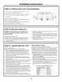
lSTEP31REMOVE
BEFORE YOU BEGIN:
CUSTOM
PANEL INSTALLATION:
Ifvou intend
ACCESS COVER
to
install custom door panels, (on some models) refer to
trim kit installation instructions. Custom panels should
be in place bet0re installing tile dishwasher.
ISTEP 1] REMOVE
PACKAGING
Cut tile shipping
carton and use it as a pad beneath
tile
dishwasher.
This will protect tile finished
floor in tile
kitchen.
AccessCoverJuncti°_c"
• Remove wrapping
and uncoil tile drain hose in tile
back of tile dishwasher.
Do not remove rear insulation
blanket,
• Lay the dishwasher
the drain hose,
on it's back,
Do not kink or crush
• ReIllOX e sol/nO instllation
[STEP 2] INSTALL LEVELING
plate.
• Install
LEGS
UL listed
strain
board
relief
and
tile access
on.jUllCtioi_
coxer
box.
Min.
l STEP 41 INSTALL 90 ° ELBOW
Rernove
RedPlugs
Unscrew
RearLegsto
Installation
Height
Rear
Insulation
Blanket
• Measm'e installation
opening
fi'om tile floor to tile
bottom
of tile co/mtertop.
• Install tile fl'ont leveling legs into holes on tile brackets. Use a wrench to screw tile legs in until tile overall
height of tile dishwasher
is 1/4" less than tile installation opening
height.
Note: InstaU the legs as shown, 1-1/4" min from the
bottom of the bracket.
• Remove
holes.
and
discard
tile red plugs
• Install
tile 90 ° elbow
onto
tile water
inlet.
Use thread
seal tape or pipe thread compo/md.
Thread
seal tape
should be wrapped
in sam e direction
as tile threads on
tile elbow.
• Tile 90 ° elbow should time tile inlet water line.
fl'om tile fl'ont
10
Installation
Instructions
[STEP 5] INSTALL POWER CORD
[STEP 7] SLIDE DISHWASHER
INTO OPENING
SKIP THIS STEP IF DISHWASHER
WILL BE DIRECT WIRED
DO NOT PUSH
• Maxim mn power cord length is 6 ft.
• The power cord and connections
must comply with
the National
Electrical
Code, Section 422 and/or
local codes and ordinances.
KNEES,
AGAINST
DAMAGE
WILL
THE FRONT
PANEL WITH
OCCUR!
• Insert draii_ hose into the cabinet wall hole. If a power
cord is used, guide the end through
a separate
hole.
Insert power cord wires
through strain relief and
tighten.
• Position water supply line and house wn'ing on the
floor of the opening
to avoid interterence
with base
of dishwasher.
• Strip 1/2" insulation
fi'om ends of power
cord
• Slide dishwasher
into the opening
a Jew inches at a
time. As you proceed,
pull the drain hose through
the
cabinet wall under the sink.
• Check to be sure there is 11o interterence
with
wires.
• Comlect
incoming
power cord white to dishwasher
white, black to black and grom/d to dishwasher
green
wire. Use UL listed wire c(mnectors
of appropriate
size.
• Install junction
box cover with screws provided.
Be sure
wires are not pinched
under the cover.
waterline
or house wiring.
• Again, check to be sure the dishwasher
[STEP 61 LEVEL DISHWASHER
• Careflflly, upright
the dishwasher,
bend the leveling legs.
• Check to be sm'e the dishwasher
ac!justed
to fit the installation
be careful
[STEP 8] CONNECT
WATER LINE
not to
NOTE: If you are using an existing water line, cut 1" off
the end. Always use a new ferrule and compression
mlt.
• The water supply line should be flushed to clear anv
fi)reign material
betore c(mnecting
to the dishwasher.
• Make sure there are 11o sharp bends or kinks to restrict
water flow.
• Insert water line into the 90 ° elbow.
is level and is
cutout
is level.
height.
Level
Top
and
Sides
• Slide terrule
against
elbow and secm'e with
COll/pFession
• Replace
plate.
Compression
Nut
n/lt.
access
panel
Hot Water
90° Elbow SupplyLine
11
Installation
[STEP 9] CONNECT
Instructions
DRAIN LINE
[STEP 101 CONNECT
ELECTRICAL
FOLLOW ALL LOCAL CODES AND ORDINANCES.
FOR DIRECT WIRE ONLY
(If a power
• The dishwasher
is supplied with a 72" long drain hose.
• If a hmger drain hose is required,
add up to 48" of
length for a total of ] 0 ft. length.
• Secure the drain hose to the air gap, waste tee or
disposer with damps.
• Make sm'e drain hose is not kinked.
outlet
cord
and
with
continue
plug
with
is used,
next
plug
it into
the
wall
step.)
turned off at the
source.
Verify that power is
o_
)
6r
IMPORTANT:
When comaecting
drain line to disposer,
check to be
sure that drain plug has been
removed,
DISH_VASHER
WILL
NOT DI_MN IF PLUG IS LEFT
IN PIACE,
Method
Insert power cord wires
through strain relief and
tighten.
Plug
Remove
[_4_
1 - Air gap with waste tee or disposer
•
Locate
green)
small
the
three
with
hole
dishwasher
stripped
in the
• Install
Waste Tee Installation
DisposerInstallation
to be
• Reinstall
should
Method 2 - High drain loop with waste tee or disposer
Waste Tee Installation
Fastento underside
of countertop
junction
sure
that
wires,
ends.
Insert
junction
comaect
incoming
black
to black.
_ ___
-White
box.
grotmd
box
cover
wires
are
Insulation
be secm'ed
Use
wire
to green,
with
not
black
through
com_ectors
white
screws
and
the
provided.
pinched
to
to white
under
and
Check
the
cover.
Board
in position.
The board
so it does not interfere
with door
opening.
Fasten to underside
_
of countertop
If house
wiring
gromM,
a gromM
by the
30"
installer.
alumimmL
is not
2-wire
must
When
be sure
anti-oxidant
with
be provided
house
wiring
to use/JL
compomM
n/llIl-to-coppeI"
Waste Tee Installation
(white,
wire
is
Listed
and
alumi-
connectoFs,
Disposer Installation
Si l'installation
_lectrique
de la maison
n'est pas h deux ills plus
l'installateur
dolt installer
raise
h la terre.
_lectrique
minium,
des
connecteurs
12
compos_s
aluminium
Si l'installation
de la maison
il flint
terre,
tm fil de
est
prendre
soin
antioxydants
h cuivre
sur
en alud'utiliser
et des
la liste UL.
Installation
Instructions
I STEP 111 POSITION AND LEVEL THE DISHWASHER
• Check
to be sure tile dishwasher
is a(!justed
to correct
height and is centered
in tile ctltotlt.
• Open and close tile door to insure proper
operation
tile door. If there is any binding
or rubbing,
rea(!just
leveling
DoorRub Door
OnRight OnLeft
of
Adjust
This
Leg
legs.
Use a wrench to make adjustments.
• If the door rubs on the right side of the cabinet, extend the left rear
leg by unscrewing it one quarter turn.
• If the door rubs against the left side of the cabinet, extend the right
rear leg by unscrewing it one quarter turn.
• Check level again. Repeat the procedure if necessary.
Adjust
This
Leg
[STEP 12] PRE-TEST CHECK LIST
[] Verify water supply and drain lines are not kinked or in contact
with other components.
[] Turn on the sink hot water faucet and verify water temperature.
Incoming water temperature must be between 120°Fand 150°E
120°Fmin. temperature is required for best wash performance.
[] Turn on water supply.
[] Open the door. Check to be sure Insulation Board does not
interfere with door opening.
Installation service calls are not covered by your
warranty. To avoid unnecessary charges, review
this list carefully.
[] Checkto be sure power is 0FE
[] Open the door and remove all foam and paper packaging.
[] Pull lower rack out, about halfway. Check to be sure it does
not roll back or forwards on the door. If the rack moves,
adjust leveling legs.
I STEP 13] DISHWASHER
WET TEST
[] Turn on power supply.
[] Select the normal cycle and press the start button.
[] The control will indicate a slow/no fill by flashing the CHINA
CRYSTAL LIGHTWASH OR WASH CYCLElight. Check water
supply, then adjust fill time according to the chart shown.
[] Check to be sure that water enters the dishwasher, wait up to
2 minutes. If water does not enter the dishwasher, check to be
sure that water is turned on.
[] Check for leaks under the dishwasher. If a leak is found, turn
power and water off, then tighten connections. Restore power
and water supply.
[] Check for leaks around the door. A leak around the door could be
caused by door rubbing or hitting against adjacent cabinetry.
Reposition the dishwasher if necessary.
[] After the dishwasher drains check drain lines. If leaks are found,
turn power off, correct as necessary.
[] The control will indicate a slow/no drain by flashing the RINSE
ONLY,SANI WASH or HEAT OPTIONS.Check that the airgap is
clear of debris and that the knockout in the disposer or waste tee
is fully removed. Check that the drain hose is not kinked.
[] Open the dishwasher door and make sure that most of the water
has drained. If not, check that disposer plug has been removed
and that air gap is not plugged.
[] Cancel the dishwasher cycle and complete the installation.
[] Remove protective film if present from the control panel and door.
13
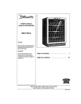
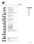
CHECK WATER FILL LEVEL
For best performance, check the water fill level.
Run through a complete RINSE ONLYcycle to ensure it is emptying
and filling correctly. For low water pressure situations run the
RINSE ONLYcycle 3 times. Half-way through the final RINSE ONLY
cycle, pause the dishwasher and check the water level inside the
dishwasher. If the water level is not above the minimum water level
(marked on the lower spray support tower), increase the fill level.
1. Ensure the dishwasher is not running through a cycle. Depress
the WATER TEMP button for 10 seconds until the second buzzer
sounds (except on ZBD6600).
2. Press the START/CANCELbutton to select fill time, as per chart
(65 seconds is the factory setting).
3. To test time, press DELAYSTART.The dishwasher will start filling.
Listen for the dishwasher to complete filling. Once filled, the fill
level must be checked to ensure fill time is correct.
4. Once complete, press the WATER TEMP button to exit fill time
mode.
Continue to press the START/CANCELbutton
until the desired indicator is illuminated.
CycleStatue Indicators
SENSING
Fill Time
60 seconds
WASHING
65 seconds
RINSING
DRYING
70 seconds
80 seconds
CLEAN
90 seconds
Installation
Instructions
[STEP 14] SECURE DISHWASHER
TO CABINET AND
COUNTERTOP
To maintain
position
and aligmnent,
the dislmashei
must be secured to the countertop
and ac!jacent
cabin ets.
Secure dishwasher
to countertop:
• Drill pilot holes through
the motmting
into the ui_derside
of the coui_tertop.
[STEP 151 INSTALL TOEKICK
• Loosen depth
ac!j ustm ent screws
inside the
bracket.
• Slide bracket
out
_
Depth
to proper
depth.
Tighten
screws.
bracket and
Secure with
• Attach supplied
toekick to
brackets with
screws A prox ided.
SCI'eWS
Screw_
J
Tighten
//
C
provided.
Do not tighten.
• At!just the toekick
to touch the floor.
/
/
Adjust to
Toekick
Attachment Screws
screws.
,
Adjustto TouchFloor
INSTALL A
CONTINUOUS
CUSTOM
TOEKICK
Notchthe continuous
toekickto allowthe door
panelto swing underthe
dishwasher.
IMPORTANT:
To avoid damage to your dishwasher,
drive screws straight and flush. Protruding
screw heads
may scratch the top of the escutcheon
or door mid cm_
interfere
with door closing.
Secure dishwasher
to adjacent cabinets:
• Remove plastic plugs button on the inside
dishwasheI _fl'ame. One on each side.
• Drill pilot holes through
the dishwasher
into the ac!jacent cabinets.
Install screws
• Replace plastic plug buttons.
T
A contintlOtlS
CtlStOUl
toekick is
_'k)F
models with long CtlStOUl door panels.
• Cut a notch in the toekick deep enough
to allow the
door to swing fl'eelv trader the dishwasher.
• Check for interterence
by slowly opening
and closing
the door. If the door touches the toekick, triln to
of the
holes and
B provided.
prevent
iI]terfereI]ce.
• Secure the toekick to ac!jacent cabinets in such a
umlmer
that it inav be i'emoved if selwice is required.
[STEP 16] ADJUST
lug Butt0ns_-_
recou/iuended
• Open the door fully.
• Loosen
(but do not
_-_
reI//ove)
Screw B
screws
holding
the top and side trims.
• At!just trilu to coyer
opening
gap. Tighten
screws.
14
SIDE TRIM STRIPS
.
AdjustSideTrim .
_""Pto Meet Cabinetry_''_
Panel Installation
for Models ZBD7000 and ZBD7005
The custom panel should be prepared by your
cabinet manufacturer according to the instructions
shown on page 9. Use the supplied installation
template to locate the mounting screws for the
door.
[STEP 4] INSTALL CUSTOM
Screws Must
Be Countersunk
Into Panel
|
E_
HANDLE
'_4-1/2" Max.
FromTop
of Panel
ISTEP 11DRAW
Handle
CENTERLINE
• Place
the
custon]
fiat sm'thce
side down.
• Locate
the
the
on
Custom
Door Panel
a
appearance
vertical
at the
A custom
center
of
top.
a carpenters
square
a centerline
fl'om
drmv
1o
with
panel
• Use
panel
handle
before
the
panel
• The
handle
ac!jacent
to
of the
cabinet
top
must
should
drmver
be installed
is secured
be
installed
handles,
panel.
Secure
handles.
onto
to the
the
or
the
so that
4-1/2"
handle
panel
dishwasher
door.
it aligns
max.
in the
fl'om
same
with
the
top
rammer
as
bottoIll.
STEP 5]INSTALL PANEL
[STEP 2]ALIGN TEMPLATE
TO PANEL
• Trim
template
dotted
line
• Place
panel
edge
Use
• Use
all
template
aligned
and
with
the
sides.
on
the
the
top
ScrewHoles
centerline.
tape to hold
in place.
an awl to mark
the
screw
hole
• Remove
locations
the
the
bottom
slots.
on the
along
the
• Secure
panel
shoulder
to the
• Make
sm'e
• Press
the
panel
all 4 washers
until
the
washers
are
slots.
sides.
The
panel
should
by inserting
door
washers
into
the
engage
against
the
flflly
the
door
and
engaged
align
the
matching
evenly
keyhole
downwards
the
with
and
slots.
push
into
top
kevhole
the
key hole
top
and
Custom
Panel
indicated
on
the
template.
template.
Dishwasher
Door
ISTEP 3IINSTALL MOUNTING
SCREWS
If the
be
panel
AND WASHERS
3/4"
thick,
#S x 3/8"
screws
fi)r
drill bit
locations.
to drill
pilot
is less
used./_)se
• Use a 3/32"
the marked
Note:
door
The
with
the
panel
shoulder
shoulder
supplied
than
custom
the
The washer
will
washer
door.
• Place
ShoulderWashers
EngageKeyhole
Slots
slip into
#8 x 1/2
the
over
screws
keyhole
slots
must
panels.
3/32"
to the
and
one
screws
thick
holes
is secured
washers
washer
shorter
1/2"
deep
dishwasher
provided.
on the
dish-
Shoulder
Screw
Washer
/
hole
Phillips
pan
head
washers
and
screws
and
in
drive
wood
Stand
upright.
Open dishwasher
door
and drive the supplied
#6 x 2 Phillips screws
through
the im]er door
and into the custom
the
screws
into
panel. Drive one screw
at the top and one on
each side as shown.
panel.
• Install remaining
locations.
in the
the dishwasher
marked
15
Panel
Note: While performing installations described in this book,
safety glasses or goggles should be worn.
For Motion'ram
1-800-444-1845.
TM
local s_,r_,ice i_ )our area, call
Note: Product
improvement
is a continuing
endeavor
at
General
Electric.
ThereIore,
materials,
appearance
and
specifications
are sul)ject
to change
without
notice.
Monogram:
General Electric Company
Louisville, KY40225
0616400 327
Pub.No.49-5905-2
Dwg.No. 165D4700P231
(N.D.131) 1/02