1
12/07 Rev. 3.03-01
USER + SERVICE MANUAL
TTX x50/67x – TTX Laminator –S 45/65/95/105 – TDI/STDI – TTK – ALX720
Info Printouts and Parameters
Off-line menu structure .................................. 3
Important setting instructions ..................... 3
Area of application ..................................... 3
Operation parameter menu............................ 4
TTX / TDI / TTK .......................................... 4
TTX laminator............................................. 5
Parameter menu TTX (not TTX 350) ............. 6
Parameter menu TTX 350 ............................. 8
Parameter menu TTK .................................. 10
Parameter menu TDI ................................... 12
Parameter menu ALX720 (printer part)........ 14
Parameter menu TTX Laminator ................. 16
INFO Info printouts....................................... 17
STA0 Report parameter settings........... 17
STA1 Logo buffer, memory report......... 17
STA2 Font library .................................. 18
STA3 Service report .............................. 18
STA4 Report parameter
settings/service............................ 19
DOT1 Print test for punched material .... 19
DOT2 Print test for endless material...... 19
PRTP Printer parameters............................. 20
PSPD Print speed .................................. 20
MTYP Material type................................ 20
MLEN Setting material length................. 20
MWID Setting material width .................. 21
CLAB Setting change label.................... 21
CLEN Setting label length...................... 21
PUNO Gap offset.................................... 22
BCHI Bar code height ........................... 22
UPCA Bar code plain copy line .............. 22
CSPD Cut speed .................................... 23
CPOS Cut position ................................. 23
ASPD Applicator speed.......................... 23
ADIS Applicator distance ...................... 23
MPOS Dispense position ........................ 24
CWID Cut width ..................................... 24
CDIS Double cut function...................... 24
XPOS Print offset on the X-axis ............. 26
YPOS Print offset on the Y-axis ............. 26
Colour print offset equalisation.... 26
FBY
SSPD Feed without printing....................27
Gap detection mode.....................27
GAP
CMOD Cut mode .....................................28
CBAK Reverse step after cut..................30
CLST Ejection of last printed labels ......31
DMOD Dispensing mode .........................31
LAMP Laminator parameters........................32
LSPD Laminating speed.........................32
LADJ Setting the laminate dancer .........32
MADJ Setting the material dancer rod....32
IFAC Interface parameters ...........................33
PORT Interface type ...............................33
SPOL Spooler size .................................33
BMOD Spooler mode...............................33
<20H Filter for characters smaller than
20H ..............................................33
BAUD Data transfer speed .....................34
PARI Parity............................................34
DBIT No. of data bits.............................34
SBIT No. of stop bits .............................34
HAND Data synchronisation ...................34
PRID Printer identification no. ...............34
SYSP System parameters............................35
EMUL Print interpreter ............................35
NACH Character sets..............................36
SENS Photoelectric switch, beginning of
label .............................................36
PUNS Material photoelectric switch........37
FMOD Ribbon automatic economy .........37
L-R
LH/RH machine version ...............38
SW01 Loop control printer ......................38
SW02 Lopp control dispenser.................38
OMOD On-line/off-line stand-by...............39
MMOD Material type, single
label/Leporello..............................39
LMOD Laminate end ...............................39
LPOS Label position of the first label .....39
SECF Activation Second Feed ...............39
MPSF Feed length Second Feed............40
SMOD Single job mode ...........................40
D_HD Short/long dispensing edge .........40
FMOT Feed motor on/off.........................40
12/07 Rev. 3.03-01
USER + SERVICE MANUAL
TTX x50/67x – TTX Laminator –S 45/65/95/105 – TDI/STDI – TTK – ALX720
EXTR Single start / stacker.................... 40
SGMO Edge input signal......................... 41
CODE Password..................................... 42
HRES Print head resistance................... 43
HEAT Lowering the head temperature .. 43
HVOF Offset for head voltage ................ 44
EXLO Expand logo ................................ 44
CLCK Realtime clock ............................. 44
USMD Single start .................................. 45
LREP Routine gap sensing.................... 45
COPY Reprint last printed label.............. 45
CSET Using character sets.................... 45
MEND Material end detection ................. 46
SCAN Scanner mode ............................. 46
SERR No. of permitted read errors ........ 46
MSET Threshold material end detection 46
PEPH Peripheral devices....................... 47
JCLR Delete print job................................... 50
SCLR Delete printer memory....................... 50
OTHR Special functions (Others) ................ 51
DOWN Downloading logo/characters ...... 51
LCLR Formatting logo card ................... 51
CCLR Formatting colour card .................52
ICLR Formatting image card .................53
ADJS Scanner adjustment .....................54
MCHK Memory check..............................54
SCHK Sensor check ...............................54
PCHK Demo print ...................................57
FACT Factory settings............................58
SERV Only for Service ...........................58
NULL Only for Service ...........................58
HADJ Only for Service ...........................58
ACSC Only for Service: Scanner ............58
HVxx Print head temperature .......................59
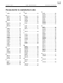
Parameterlist in alphabetical order ...............60
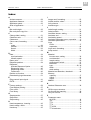
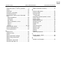
Index.............................................................61
3
12/07 Rev. 3.03-01
USER + SERVICE MANUAL
Info Printouts and Parameters
TTX x50/67x – TTX Laminator –S 45/65/95/105 – TDI/STDI – TTK – ALX720
Off-line menu structure
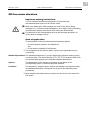
Important setting instructions
You can set/alter the different parameters of the printer and
activate/deactivate options in the off-line mode.
With some parameters, false settings can result in the device being
damaged (e. g. if the print head temperature is too high). During formatting,
and with other settings, data and/or print orders are also deleted.
Pay attention to the corresponding notes in the following description to
ensure that no damage occurs!
Area of application
This description of the info printouts and parameters applies
– for all the devices shown in the header bar
and
– for the options available for this device.
The assignment to the options (table) is given in the parameter menus
(overviews).
Standard parameters The standard parameters (1) are for determining the basic settings of any
one device type. The device families (TTX, TDI, TTX Laminator) differ from
one another with regards to the available standard parameters.
Options
The parameters for the options only appear in the display if the
corresponding option or firmware has been installed.
Laminator
The laminator is a special option with its own display and parameter menu.
Its standard parameters correspond only in part to the standard printer
parameters.
More detailed information about an option can be found in the manual for
this option.
4
12/07 Rev. 3.03-01
USER + SERVICE MANUAL
Info Printouts and Parameters
TTX x50/67x – TTX Laminator –S 45/65/95/105 – TDI/STDI – TTK – ALX720
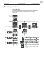
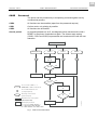
Operation parameter menu
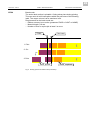
TTX / TDI / TTK
The following illustration shows the operating principle of the parameter
menu on control units with the square buttons CUT, FEED and
ON/OFFLINE.
5
12/07 Rev. 3.03-01
USER + SERVICE MANUAL
Info Printouts and Parameters
TTX x50/67x – TTX Laminator –S 45/65/95/105 – TDI/STDI – TTK – ALX720
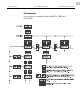
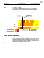
TTX laminator
The following illustration shows the operating principle of the parameter
menu on control units with the square buttons CUT, FEED and
ON/OFFLINE.
6
12/07 Rev. 3.03-01
USER + SERVICE MANUAL
Info Printouts and Parameters
TTX x50/67x – TTX Laminator –S 45/65/95/105 – TDI/STDI – TTK – ALX720
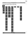
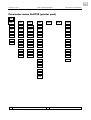
Parameter menu TTX (not TTX 350)
OFF
INFO
PRTP
IFAC
SYSP
STA0
PSPD
PORT
EMUL
DOWN
STA1
MTYP
SPOL
NACH
LCLR
STA2
MLEN
BMOD
SENS
CCLR
6
STA3
MWID
<20H
PUNS
ICLR
8
DOT1
CLAB
BAUD
FMOD
ADJS
5
DOT2
CLEN
PARI
OMOD
MCHK
PUNO
DBIT
SMOD
SCHK
BCHI
SBIT
D_HD
4
PCHK
UPCA
HAND
FMOT 4
FACT
PRID
EXTR
SERV
7
CPOS 2
SGMO
NULL
7
ASPD
3
CODE
HADJ
7
ADIS
3
HRES
ACSC
7
MPOS 4
HEAT
CWID
2
EXLO
CDIS
2
HVOF
CSPD
2
XPOS
CLCK
YPOS
USMD
FBY
6
JCLR
SCLR
9
LREP
SSPD
COPY
GAP
CSET
CMOD 2
MEND
DMOD 4
SCAN
5
SERR
5
PEPH
Standard
6
Colour option only
OTHR
7
12/07 Rev. 3.03-01
USER + SERVICE MANUAL
Info Printouts and Parameters
TTX x50/67x – TTX Laminator –S 45/65/95/105 – TDI/STDI – TTK – ALX720
2
Cutter only
7
For service only
3
Dispenser/applicator only
8
Image card software only
Only with 8dot-emulation-firmware (z.B. 1E42)
4
Dispenser only
9
5
Scanner only
10
8
12/07 Rev. 3.03-01
USER + SERVICE MANUAL
Info Printouts and Parameters
TTX x50/67x – TTX Laminator –S 45/65/95/105 – TDI/STDI – TTK – ALX720
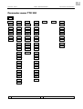
Parameter menu TTX 350
OFF
INFO
PRTP
IFAC
SYSP
STA0
PSPD
PORT
EMUL
DOWN
STA1
MTYP
SPOL
NACH
LCLR
STA2
MLEN
BMOD
SENS
MCHK
STA3
MWID
<20H
PUNS
SCHK
DOT1
CLAB
BAUD
FMOD
PCHK
DOT2
CLEN
PARI
OMOD
FACT
PUNO
DBIT
SMOD
SERV
6
BCHI
SBIT
EXTR
NULL
6
UPCA
HAND
SGMO 5
PRID
CODE
CSPD
Standard
5
2
CPOS 2
HRES
MPOS 4
HVOF
CWID
2
CLCK
CDIS
3
USMD
XPOS
LREP
YPOS
CSET
SSPD
MEND
GAP
MSET
CBAK
2
CLST
2
JCLR
SCLR
5
PEPH
6
Only for Service
OTHR
9
12/07 Rev. 3.03-01
USER + SERVICE MANUAL
TTX x50/67x – TTX Laminator –S 45/65/95/105 – TDI/STDI – TTK – ALX720
2
Only with cutter or stacker
7
3
Only with cutter
8
4
Only with dispenser or tear-off edge
9
5
Not with dispenser
10
Info Printouts and Parameters
10
12/07 Rev. 3.03-01
USER + SERVICE MANUAL
Info Printouts and Parameters
TTX x50/67x – TTX Laminator –S 45/65/95/105 – TDI/STDI – TTK – ALX720
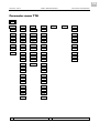
Parameter menu TTK
OFF
INFO
PRTP
IFAC
SYSP
STA0
PSPD
PORT
EMUL
DOWN
STA1
MTYP
SPOL
NACH
LCLR
STA2
MLEN
BMOD
SENS
MCHK
STA3
MWID
<20H
PUNS
SCHK
STA4
CLAB
BAUD
FMOD
PCHK
DOT1
PUNO
PARI
OMOD
FACT
DOT2
BCHI
DBIT
SMOD
SERV
7
UPCA
SBIT
EXTR
NULL
7
2
HAND
SGMO
HADJ
7
CPOS 2
PRID
CODE
CSPD
Standard
CWID
2
HRES
CDIS
2
HEAT
XPOS
HVOF
YPOS
CLCK
SSPD
USMD
GAP
LREP
CMOD 2
CSET
CBAK
4
MEND
CLST
2
PEPH
JCLR
6
SCLR
OTHR
11
12/07 Rev. 3.03-01
USER + SERVICE MANUAL
TTX x50/67x – TTX Laminator –S 45/65/95/105 – TDI/STDI – TTK – ALX720
2
Cutter only
3
4
5
7
8
Dispenser only
9
10
For service only
Info Printouts and Parameters
12
12/07 Rev. 3.03-01
USER + SERVICE MANUAL
Info Printouts and Parameters
TTX x50/67x – TTX Laminator –S 45/65/95/105 – TDI/STDI – TTK – ALX720
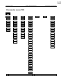
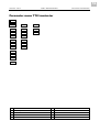
Parameter menu TDI
OFF
INFO
PRTP
IFAC
SYSP
JCLR
STA0
PSPD
PORT
EMUL
DOWN
STA1
MTYP
SPOL
NACH
LCLR
STA2
MLEN
BMOD
SENS
CCLR
6
STA3
MWID
BAUD
PUNS
ICLR
8
DOT1
PUNO
PARI
FMOD
ADJS
5
DOT2
BCHI
DBIT
OMOD
MCHK
UPCA
SBIT
SMOD
SCHK
XPOS
HAND
MMOD
PCHK
YPOS
PRID
LPOS
FACT
SSPD
SECF
SERV
7
GAP
MPSF
NULL
7
EXTR
HADJ
7
CODE
ACSC
7
HRES
HEAT
HVOF
CLCK
USMD
LREP
COPY
CSET
MEND
Standard
SCAN
5
SERR
5
6
Colour option only
SCLR
OTHR
13
12/07 Rev. 3.03-01
USER + SERVICE MANUAL
TTX x50/67x – TTX Laminator –S 45/65/95/105 – TDI/STDI – TTK – ALX720
2
7
For service only
3
8
Image card software only
4
5
9
Scanner only
10
Info Printouts and Parameters
14
12/07 Rev. 3.03-01
USER + SERVICE MANUAL
Info Printouts and Parameters
TTX x50/67x – TTX Laminator –S 45/65/95/105 – TDI/STDI – TTK – ALX720
Parameter menu ALX720 (printer part)
OFF
INFO
PRTP
IFAC
SYSP
STA0
PSPD
PORT
EMUL
DOWN
STA1
MLEN
SPOL
NACH
LCLR
STA2
MWID
BMOD
PUNS
MCHK
STA3
PUNO
<20H
FMOD
SCHK
DOT1
BCHI
BAUD
L-R
PCHK
DOT2
UPCA
PARI
SW01
FACT
XPOS
DBIT
SW02
SERV
7
YPOS
SBIT
OMOD
TEST
7
SSPD
HAND
CODE
SENS
7
GAP
PRID
HRES
NULL
7
HEAT
HADJ
7
HVOF
CLCK
LREP
CSET
MEND
7
For service only
JCLR
SCLR
OTHR
15
12/07 Rev. 3.03-01
USER + SERVICE MANUAL
TTX x50/67x – TTX Laminator –S 45/65/95/105 – TDI/STDI – TTK – ALX720
Info Printouts and Parameters
16
12/07 Rev. 3.03-01
USER + SERVICE MANUAL
TTX x50/67x – TTX Laminator –S 45/65/95/105 – TDI/STDI – TTK – ALX720
Parameter menu TTX Laminator
OFF
LAMP
SYSP
OTHR
LSPD
SENS
SCHK
MTYP
PUNS
FACT
MLEN
EXTR
PUNO
CODE
CSPD
2
LREP
CPOS 2
PEPH
CWID
2
GAP
LADJ
MADJ
2
Standard
6
Cutter only
7
3
8
4
9
5
10
Info Printouts and Parameters
17
12/07 Rev. 3.03-01
USER + SERVICE MANUAL
Info Printouts and Parameters
TTX x50/67x – TTX Laminator –S 45/65/95/105 – TDI/STDI – TTK – ALX720
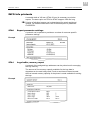
INFO Info printouts
A material width of 100 mm (STA4: 50 mm) is necessary to print the
reports. The status print out STA0 to STA3 is approx. 200 mm long.
Printing of individual reports can be deactivated for certain peripheral
options. For detailed information refer to the description of parameter
SYSP/PEPH.
STA0
Report parameter settings
A protocol can be printed to provide an overview of customer-specific
parameter settings.
Example
STA1
Logo buffer, memory report
A protocol of the assigned logo addresses can be printed out for managing
the logo memory.
The amount of free memory capacity available for the logo data is
dependent on the card being used. If such a card has not been inserted,
the free internal memory capacity of the printer is made available for storing
the logo.
Example
18
12/07 Rev. 3.03-01
USER + SERVICE MANUAL
Info Printouts and Parameters
TTX x50/67x – TTX Laminator –S 45/65/95/105 – TDI/STDI – TTK – ALX720
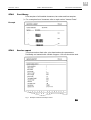
STA2
Font library
Print samples of all installed characters, bar codes and line samples.
For a complete list of characters refer to topic section "Internal Fonts".
Example
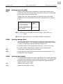
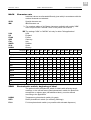
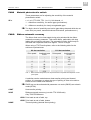
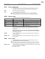
STA3
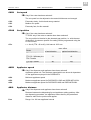
Service report
Test printout about feed roller, print head and service parameters.
Preferably reel material with a width of approx. 100 mm should be used.
Fig. 1 Example of the Service Report STA3.
19
12/07 Rev. 3.03-01
USER + SERVICE MANUAL
Info Printouts and Parameters
TTX x50/67x – TTX Laminator –S 45/65/95/105 – TDI/STDI – TTK – ALX720
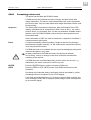
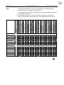
Counter
Max. value
Service Operations
Head number
255
Roll number
Knife number
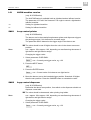
STA4
Head run length
131 km
Roll run length
8.800 Jahre
Cuts on knife
4.300.000.000
Total material length
430.000 km
Total foil length
430.000 km
Total cuts
4.300.000.000
Total head moves
4.300.000.000
Head strobes
4.300.000.000
Operation time
8.800 Jahre
Report parameter settings/service
(Only TTK)
Report STA4 prints the most important data contained on STA0 and STA3
on 50 mm wide material.
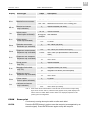
DOT1
Print test for punched material
Special pattern for highlighting absent dots on the thermal bar. The test is
concluded using the ENTER button.
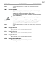
DOT2
Print test for endless material
Special pattern for highlighting absent dots on the thermal bar. The test is
concluded using the ENTER button.
20
12/07 Rev. 3.03-01
USER + SERVICE MANUAL
Info Printouts and Parameters
TTX x50/67x – TTX Laminator –S 45/65/95/105 – TDI/STDI – TTK – ALX720
PRTP Printer parameters
PSPD
Print speed
The print speed (material feed) can be adjusted according to the ribbon and
material combination being used in order to optimise the contrast depth and
the density of the print image.
PS 4
Minimum print speed = 4 inches per second
PS 12
Maximum print speed = 12 inches per second
(not with TTX 350/OCELOT)
Progression
Unit interval = 1 inch/s
MTYP
Material type
Definition of the materials used. A distinction is made between reel material
and punched material (hole punches, self-adhesive material with register
punch holes). The detected punch position corresponds to the start of the
label.
The value is overwritten by the appropriate Easy Plug command when
sending label formats.
ENDL
If material without gaps is to be used
PUN
If material with gaps is to be used
MLEN
Setting material length
The material length (label length) is the distance between the gaps,
measured from the front edge (beginning) of a label to the front edge of the
next label.
The value is overwritten by the appropriate Easy Plug command when
sending label formats.
L5
Minimum length input = 5 mm
Lxxx
Maximum length input (depending on print head width and memory
configuration, see also STA0)
Progression
Unit interval = 1 mm
21
12/07 Rev. 3.03-01
USER + SERVICE MANUAL
Info Printouts and Parameters
TTX x50/67x – TTX Laminator –S 45/65/95/105 – TDI/STDI – TTK – ALX720
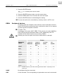
MWID
Setting material width
Wxxx
Setting of the material width. Important for mirroring the printout at the
center line (Easy Plug command #Z), because the centre line is calculated
as the middle of the set material width.
Setting range: min. width (depending on the device) up to max. width
(depending on print head width and memory configuration); Unit interval:
1 mm.
Printer
min. width
in mm
TTX x50 / Wildcats
20
TTX 67x / Wildcats plus
20
TTK / Texxtile
15
Tab. 1
Minimal setable material width, depending on the printer type.
The parameter can be used to set the left margin, if the printer is in
Lineprinter mode.
With ALX right hand devices, the setting of MWID is insignificatn.
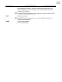
CLAB
Setting change label
A change label can be controlled either by sending the appropriate Easy
Plug command (#ER), or as a standard setting at the end of every print job.
The latter is achieved by setting parameter CLAB to YES.
•
•
Continuous material: The change label is printed on and 10 mm longer.
Punched material: A blank label is added to the last printed label.
STD
Change label caused by Easy Plug command
YES
Change label is produced at the end of every print job regardless of any
existing Easy Plug command.
CLEN
Setting label length
The change label length is the extra length added to the normal label length
of the print job to separate 2 print jobs with a larger label. The change label
length can only be set when using reel material. With gap material the
length is always 1 label length.
C0
Minimum extra length = 0 mm
C 30
Maximum extra length = 30 mm
22
12/07 Rev. 3.03-01
USER + SERVICE MANUAL
Info Printouts and Parameters
TTX x50/67x – TTX Laminator –S 45/65/95/105 – TDI/STDI – TTK – ALX720
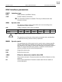
PUNO
Gap offset
The zero position can be determined in millimeters offset in (+) or against () the feed direction from the detected gap position.
The value is overwritten by the appropriate Easy Plug command when
sending label formats.
Pxxx
BCHI
xxx = -15 to 300 (TTX 350: -50 to 300); Unit interval: 1 mm
Bar code height
The barcode height can be changed by a factor of between 1 and 10 mm
(BCHI factor).
B1
Smallest progression factor
B 10
Largest progression factor
Progression
Unit interval = 1 mm
The effective bar code height is calculated by multiplying the value in the
label layout (mask) by the BCHI enlargement factor.
Effective barcode height = (layout value + 1) * BCHI
Example
UPCA
The value BCHI = B 3 is set. With the Easy Plug command in the label
layout, the value /4/ is given as the bar code height (1 is standard).
Result: (4 + 1) * 3 = 15 mm
The bar code is printed with a height of 15 mm
Bar code plain copy line
The position of the first and last number in the plain-copy line can be
adjusted as required.
STD
The first and last character of the UPCA or the first character on the UPCE
are moved upwards.
SPEC
All the characters in the plain-copy line are in one line below the code.
23
12/07 Rev. 3.03-01
USER + SERVICE MANUAL
Info Printouts and Parameters
TTX x50/67x – TTX Laminator –S 45/65/95/105 – TDI/STDI – TTK – ALX720
CSPD
Cut speed
Only if the cutter has been selected!
The cut speed is to be adjusted to the material thickness and strength.
CS 2
Extremely slowly; for thick and strong material
CS 3
Medium cut speed
CS 4
Extremely fast; for thin material
CPOS
Cut position
Only if the cutter has been selected!
TTX 350: only if the cutter or stacker have been selected!
The cut position is identical to the detected gap position, i.e. with the start
of the label. A customer-specific fine setting can be programmed using the
CPOS function.
CP x
x = -8 to 8 (TTK: -80 to 80); Unit interval: 0.25 mm.
Printer
max. offset
in feed direction
against feed direction
TTX x50 / Wildcats,
TTX 67x / Wildcats plus
-8
+8
TTX 350 / Ocelot
-60
+60
TTK / Texxtile
-80
+80
TDI / Texxtile
ASPD
Applicator speed
Only if the dispenser and applicator have been selected!
Applicator speed unit. The maximum speed which can be set is dependent
on the applicator employed in the DSPS/APPL.
AS 4
Minimum applicator speed
AS 6
Maximum applicator speed for DSPS/APPL/150S and DSPS/APPL/150L
AS 8
Maximum applicator speed for DSPS/APPL/80S and DSPS/APPL/80L
ADIS
Applicator distance
Only if the dispenser and applicator have been selected!
Distance between the dispensing lip and applicator waiting position. After
the dispensing procedure, the applicator lowers itself by the predefined
distance, waits for the product and applies.
D xx
Range: 0 to 180 mm applicator interval
24
12/07 Rev. 3.03-01
USER + SERVICE MANUAL
Info Printouts and Parameters
TTX x50/67x – TTX Laminator –S 45/65/95/105 – TDI/STDI – TTK – ALX720
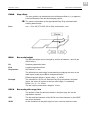
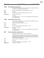
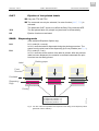
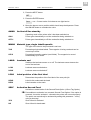
MPOS
Dispense position
Only if the dispenser has been selected!
Shifts the dispensing position by +/- the predefined value to ensure that the
label can be peeled correctly (see Fig. 2).
P xx
Range: -60 ... 0 ... 60 (equals -15 mm to +15 mm shift)
Progression
Unit interval = 0.25 mm
Dispensed label
Dispense position
Backing paper
Z0040E.cdr
Dispensing edge
Fig. 2 Dispense position of the dispensed label.
CWID
Cut width
Only if the cutter has been selected!
TTX 350: only if the cutter or stacker have been selected!
The cut width can be adjusted to the label width, ensuring that when using
narrow material the print speed can be increased, or when using wide
material that it is completely cut through.
W 25
Minimum cut width
Wxxx
Maximum cut width
Progression
Unit interval = 1 mm
CDIS
Double cut function
Only if the cutter has been selected! The CDISI double cut function should
not be used in conjunction with the stacker!
Joining grids or the gap area between the labels can be removed using a
double cut, thereby improving the outline.
The first cut is offset by the distance set from the recognized gap position
away in the feed direction, the second cut is made at the gap position.
A possible correction of the cut position (CPOS) is calculated for both cuts
and must be taken into consideration.
CD 0
Normal single cut
CD xx
Double cut function is activated, with input of the distance between the two
cuts (1.0 to 5.0 mm, corresponds to CD 4 to CD 20)
Progression
Unit interval = 0.25 mm
The smallest possible double cut distance of 1 mm must be adhered to!
25
12/07 Rev. 3.03-01
USER + SERVICE MANUAL
TTX x50/67x – TTX Laminator –S 45/65/95/105 – TDI/STDI – TTK – ALX720
Info Printouts and Parameters
26
12/07 Rev. 3.03-01
USER + SERVICE MANUAL
Info Printouts and Parameters
TTX x50/67x – TTX Laminator –S 45/65/95/105 – TDI/STDI – TTK – ALX720
XPOS
Print offset on the X-axis
The zero point of the mask is moved in relation to the edge of the label on
the X- axis, i.e. lengthways to the material.
XP 8
Maximum offset away from the edge of the label = +2 mm
XP 0
No offset
XP-8
Maximum offset towards the edge of the label = -2 mm
Progression
Unit interval = 0.25 mm
TTX/TDI:
The setting range -24...0...+24 (-6 to +6 mm) applies for 8-dot emulation
from firmware 1E42.
YPOS
Print offset on the Y-axis
The zero point of the mask is moved in relation to the gap position on the
Y-axis, i.e. in the feed direction.
CP8
Maximum offset in feed direction = +2 mm
YP 0
No offset
CP -8
Maximum offset opposed to feed direction = -2 mm
Progression
Unit interval = 0.25 mm
TTX/TDI:
The setting range -24...0...+24 (-6 to +6 mm) applies for 8-dot emulation
from firmware 1E42.
FBY
Colour print offset equalisation
Equalisation of the even print offset in colour printing.
When printing on reel material, an offset may occur between the colour
print jobs for one label during four-colour printing. If the offset between the
individual colours and on every label is almost the same, an offset value
can be entered to compensate.
F 40
Maximum offset in feed direction = +10 mm
F0
No offset
F-40
Maximum offset opposed to feed direction = -10 mm
Progression
Unit interval = 0.25mm
27
12/07 Rev. 3.03-01
USER + SERVICE MANUAL
Info Printouts and Parameters
TTX x50/67x – TTX Laminator –S 45/65/95/105 – TDI/STDI – TTK – ALX720
SSPD
Feed without printing
The feed speed can be increased between print periods, thereby reducing
the total print time, particularly with long labels with a minimum printed
surface.
SS 4
Minimum feed speed = 4 holes per second
SS12
Maximum feed speed = 12 inches per second
Progression
Unit interval = 1 inch/s
Setting
In print applications with length calculating units (e.g. consecutive
numbering), the value for the feed speed should not be set too high. This
can help to avoid alternating between abrupt braking to 0 (zero) and
acceleration to print speed.
Note
When changing the print speed (PSPD), the feed speed (SSPD) is set
equal to the print speed (PSPD). An alternative feed speed must be reentered if required.
GAP
AUTO
Gap detection mode
AUTO mode, for material with a contrast zone = gap in the label.
AUTO is the default setting, suitable for all materials, in which a difference
between labels and gap is preset at more than 2 values (see Sensor Check
description).
MAN
MAN mode, for material with several different contrast zone.
The range of the value automatically measured by the gap detection can be
defined specifically for the label material. This allows materials with highcontrast proof points within the label to be processed, which would
otherwise be measured as 'false' gaps by the system. The corresponding
setting value is then equal to, or smaller than, the value measured at the
actual gap.
Mxxx Mxxx is displayed (xxx = 0 to 255) after selecting the MAN parameter. The
value xxx stands for the current contrast within the photoelectric switch of
the material which has just been inserted. This serves to determine which
material has been inserted.
A suitable threshold value can be set after confirmation with the ENTER
button. A figure between 0 and 255 appears on the display, which can be
altered according to the required threshold value.
Example
Self-adhesive material with black bars lengthways across the label
– Reading:
Masking paper
Masking paper + label
Masking paper + label + black bars
– Setting value:
30
60
190
60
A setting value of 60 means that all readings over 60 are ignored, therefore
also the reading 190 at the black bar.
28
12/07 Rev. 3.03-01
USER + SERVICE MANUAL
Info Printouts and Parameters
TTX x50/67x – TTX Laminator –S 45/65/95/105 – TDI/STDI – TTK – ALX720
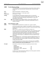
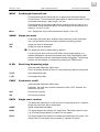
CMOD
Cut mode
Only if the cutter has been selected!
This is where the procedure for the label output and cut is defined.
R1:1
R1:1 mode (R = real):
The entire label surface is printable. The label is pushed forward to the
cutter for cutting. After the cut, the beginning of the next label is drawn back
under the print head. This reduces the output volume (in relation to a
certain time).
Cutter
Print head
1. Print
2. Print end
3. Feed
4. Return
Label, printed
Fig. 3 Printing process in Real 1:1 mode (schematic).
Label, unprinted
29
12/07 Rev. 3.03-01
USER + SERVICE MANUAL
Info Printouts and Parameters
TTX x50/67x – TTX Laminator –S 45/65/95/105 – TDI/STDI – TTK – ALX720
BTCH
Batch mode:
The entire label surface is printable. Cutting takes place during printing.
This can result in brief interruptions within the print zone of the following
label. The output volume is at its maximum level.
Requirements for the batch mode are:
– Ribbon economy is not active (parameter FMOD = CONT or NONE)
– Material length >18 mm
– Number of cuts for a print job at least 2 or more
Cutter
Print head
1. Print
2. Cut
3. Print
Label, printed
Fig. 4 Printing process in Batch mode (schematic).
Label, unprinted
30
12/07 Rev. 3.03-01
USER + SERVICE MANUAL
Info Printouts and Parameters
TTX x50/67x – TTX Laminator –S 45/65/95/105 – TDI/STDI – TTK – ALX720
N1:1
N1:1 mode (N = normal):
In N1:1 mode, cutting takes place during printing. The zero-line of the
printing is shifted 18 mm in y-direction. This offset equals the distance
cutter-printhead. Caused by this shifting, the first 18 mm of the label are not
printable. These measurement corresponds to the distance between print
head and cutter. The output volume is at its maximum level.
(The offset of the zero-line is caused historically and serves the
compatibility of older printer models).
Print head
Cutter
1. Print
2. Feed
3. cut
Non-printable area
Label, printed
Label, unprinted
Fig. 5 Printing process in Normal 1:1 mode (schematic).
CBAK
Reverse step after cut
Fundamentally, the TTX 350 cannot move the label material in the reverse
direction – with one exception: if CBAK is set to YES, the feed motor
reverses a few steps after every cut. Advantage: after the cut the material
remains a short distance from the cutter, which reduces the noise level and
improves the cut quality. Disadvantage: the printing on the edge of the label
may smudge as a result of the reverse movement.
YES
Reverse step after cutting activated
NO
Reverse step after cutting deactivated
31
12/07 Rev. 3.03-01
USER + SERVICE MANUAL
Info Printouts and Parameters
TTX x50/67x – TTX Laminator –S 45/65/95/105 – TDI/STDI – TTK – ALX720
CLST
Ejection of last printed labels
Only with TTX 350/TTK!
The command can only be selected, if a cutter function (KNIF, TCS) is
activated.
The parameter CLST equals in its effect the Easy Plug command #FE.
YES
The last printed label of a printjob is ejected and cut automatically.
NO
Ejection function not activated.
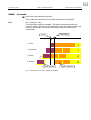
DMOD
Dispensing mode
(With activated Dispenser Option only)
N1:1
N1:1 mode (N = normal):
In N1:1 mode the label is dispensed during the printing procedure. The
space from the print head to the dispensing lip is not printable (see Fig. 6).
R1:1
R1:1 mode (R = real):
In R1:1 mode the entire surface of the label is printed. After the previous
label has been dispensed, the material is retracted underneath the print
head and can be totally printed.
Backing paper
Label
Feed
Direction
a
Printhead
b
c
Dispensing
Edge
Non-printable area with
a) Dispense position = 0
b) Dispense position < 0
c) Dispense position > 0
Z0137E.eps
Printing
Fig. 6 The size of the not imprintable area depends on the setting of the dispense position
(parameter "PRTP / MPOS").
32
12/07 Rev. 3.03-01
USER + SERVICE MANUAL
Info Printouts and Parameters
TTX x50/67x – TTX Laminator –S 45/65/95/105 – TDI/STDI – TTK – ALX720
LAMP Laminator parameters
The parameter menu of the TTX Laminator shows one specific menu item:
instead of PRTP (printer parameter), the first item is LAMP (laminator
parameter). LAMP is the header for some unique laminator parameters as
well as some of the well known printer parameters. The specific laminator
parameters are listed below.
LSPD
Laminating speed
LS 4
Minimum laminating speed = 4 inches per second.
LS10
Maximum laminating speed = 10 inches per second.
Progression
Unit interval = 1 inch per second
LADJ
Setting the laminate dancer
(only TTX laminator)
The laminate dancer controls the laminate feed. Whether laminate feed
takes place or not is dependent on the lateral deflection of the laminate
dancer. The laminate dancer also governs the feed speed according to the
lateral deflection. With the parameter LADJ the operator can set two lateral
deflection values, LNUL and LEND. LNUL: activation of the laminate feed;
LEND: deactivation of the laminate feed.
LNUL
N xx
To set the activation time. With ENTER button to N xx.
Value for LNUL (range 25 to 200), default value approx. 35. With ENTER
button to LEND.
LEND
To set the deactivation time. With ENTER button to E xx
E xx
Value for LEND (range 25 to 170), default value approx. 150. With ENTER
button to LADJ.
MADJ
Setting the material dancer rod
(only TTX laminator)
The material dancer rod controls the material feed. Whether material feed
takes place or not depends on the lateral deflection of the material dancer
rod. With the parameter MADJ the operator can set two lateral deflection
values, MNUL and MEND. MNUL: activation of the material feed; MEND:
deactivation of the material feed.
MNUL
N xx
To set the activation time. With ENTER button to N xx.
Value for MNUL (range 25 to 200), default value approx. 100. With ENTER
button to MEND.
MEND
To set the deactivation time. With ENTER button to E xx. With ENTER
button to E xx.
Value for MEND (<50). With ENTER button back to MADJ
E xx
33
12/07 Rev. 3.03-01
USER + SERVICE MANUAL
Info Printouts and Parameters
TTX x50/67x – TTX Laminator –S 45/65/95/105 – TDI/STDI – TTK – ALX720
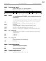
IFAC Interface parameters
PORT
Interface type
RS23
Serial interface (V24/DB25, RS232)
CENT
Parallel interface (Centronics)
The Centronics interface is standard. This may be different with older
firmware versions!
SPOL
Spooler size
The memory capacity of the printer buffer can be set according to the
requirements of each customer.
8KB
Value
Display
8 KByte (example), other values as follows:
8 KByte
16 Kbyte
32 KByte
64 KByte
8KB
16KB
32KB
64KB
All data present in the printer buffer is deleted!
The maximum print format is influenced by the spooler size, provided that
no RAM card is being used for memory expansion.
BMOD
Spooler mode
The operating mode of the spooler can be used to enter customer-specific
settings, which determine whether print series are processed individually
(the interface is only ready to receive new data after the required number of
labels of a single series has been printed), or whether several series of
spooler print data can be received during printing.
BOFF
Single print series mode
BON
Multi-print series mode
<20H
Filter for characters smaller than 20H
YES
Filter function activated. Characters smaller than 20H are filtered out of the
data flow.
NO
Filter function deactivated. Characters smaller than 20H are treated as
normal characters.
34
12/07 Rev. 3.03-01
USER + SERVICE MANUAL
Info Printouts and Parameters
TTX x50/67x – TTX Laminator –S 45/65/95/105 – TDI/STDI – TTK – ALX720
BAUD
Data transfer speed
Speed of data transfer using the serial interface.
300
300 Baud (example), other values as follows:
Value
300
600
1200
2400
4800
9600
19200
38400
Display
300
600
1200
2400
4800
9600
192.
384.
PARI
Parity
The PARI parameter defines the parity check of the data transmitted via the
serial interface.
The parity bit is for checking data transmission. If the check shows an error,
a corresponding message is displayed. The setting must be identical at the
sender and the receiver. Normally transmission is set without a parity bit.
ODD
Odd parity
A parity bit is added so that there is an odd number of 1 bits.
EVEN
Even parity
A parity bit is added so that there is an even number of 1 bits.
NONE
No check bit. Sending and receiving without check bit.
CLRP
Check bit is always 0 (zero). Sending and receiving without parity check.
DBIT
No. of data bits
This parameter can be defined in connection with both the serial and the
parallel interface
7BIT
7 data bits
8BIT
8 data bits
SBIT
No. of stop bits
Number of stop bits at the serial interface
1BIT
1 stop bit
2BIT
2 stop bit
HAND
Data synchronisation
Synchronisation at the serial interface
RTS
Data synchronisation by hardware
XON
Data synchronisation by software
PRID
IDxx
Printer identification no.
Identification number 0 - 31 (xx = 0 - 31)
35
12/07 Rev. 3.03-01
USER + SERVICE MANUAL
Info Printouts and Parameters
TTX x50/67x – TTX Laminator –S 45/65/95/105 – TDI/STDI – TTK – ALX720
SYSP System parameters
EMUL
Print interpreter
The interpreter determines the language in which the printer receives and
processes data.
Easy Plug
With Easy Plug the transmitted commands are printed as label text.
Lineprinter
In Lineprinter and Hex Dump, the commands are printed in list form with
the character set 12.
When setting Lineprinter or Hex Dump, Easy Plug commands which have
not yet been processed are deleted!
EASY
Easy Plug
LPRN
Lineprinter (Lineprinter-similar), printout of the print commands
HEXD
Printout in hexadecimal format
36
12/07 Rev. 3.03-01
USER + SERVICE MANUAL
Info Printouts and Parameters
TTX x50/67x – TTX Laminator –S 45/65/95/105 – TDI/STDI – TTK – ALX720
NACH
Character sets
Individual values are allocated differently (see table) in accordance with the
national character set selected.
SPEC
IBM
Special character set
IBM Character set
For complete tables of all fixfonts characters available with setting "IBM"
refer to topic section "Internal Fonts" in the printer user manual.
The settings "USA" to "NORW" suit only for older 7bit applications!
USA
UK
FRAN
GER
ITAL
SWED
SPAI
NORW
USA
England
France
Germany
Italy
Sweden
Spain
Norway
decimal 35
36
64
91
92
93
94
96
#
$
@
[
\
]
^
`
{
|
}
~
>127
USA
#
$
@
[
\
]
^
`
{
|
}
~
blank
UK
£
$
@
[
\
]
^
`
{
|
}
≡
blank
FRAN
£
$
à
°
ç
§
^
`
é
ù
è
~
blank
GER
#
$
§
Ä
Ö
Ü
^
`
ä
ö
ü
ß
blank
ITAL
≥
$
§
°
ç
é
^
ù
à
ò
è
`
blank
SWED
#
•
É
Ä
Ö
Å
Ü
é
ä
ö
å
ü
blank
SPAI
#
$
@
i
Ñ
Ç
^
`
¿
ñ
ç
~
blank
NORW
#
$
@
Æ
¥
Å
^
`
æ
¢
å
~
blank
SPEC
ƒ
¢
¼
½
«
•
»
±
blank
IBM
#
$
\
]
{
|
}
~
print
ASCII
123 124 125 126 127
Display:
blank blank
@
[
blank blank
^
`
blank = space, print = printable
SENS
Photoelectric switch, beginning of label
The optional reflex photoelectric switch for labels with reflecting length
markings, or the normal factory-fitted photoelectric switch for labels with
transparent or register gaps (self-adhesive labels), must be defined
according to the application.
NORM
Transparency photoelectric switch (for gaps)
REFL
Reflex photoelectric switch (for reflecting markings)
FULL
Full-size photoelectric switch (not possible with activated dispenser)
37
12/07 Rev. 3.03-01
USER + SERVICE MANUAL
Info Printouts and Parameters
TTX x50/67x – TTX Laminator –S 45/65/95/105 – TDI/STDI – TTK – ALX720
PUNS
Material photoelectric switch
These parameters are for adjusting the sensitivity of the material
photoelectric switch.
SP x
x = 1 to 8 (TTX 350, TTK: 1 to 11); Unit interval = 1
1 = Maximum sensitivity, for narrow gaps (perforations).
2 = Minimum sensitivity for clearly recognisable gaps.
Too high a level of sensitivity can lead to gaps being detected which do not
even exist (on proofs, material thickness fluctuations, perforations etc.).
FMOD
Ribbon automatic economy
The ribbon feed can be interrupted during print periods with the ribbon
automatic economy parameter. This saves ribbon, particularly with long
labels with a minimum print area. The automatic function should only be
activated with unprinted areas from approx. 10 mm in length.
When using a TTK/Texxtile printer, refer to the following table for the
minimum unprinted area:
8.0 dot resolution
Print speed
Unprinted area
in mm
4
17
5
20
6
22
7
25
8
27,5
Tab. 2
11.8 dot resolution
Print speed
Unprinted area
in mm
2
12
3
14,5
4
17
5
18,5
-
With TTK/Texxtile printers, the required minimum unprinted area depends on the
print speed.
A selection can be made between heat transfer printing and thermal
printing. It is necessary to select the type of printing in order to be able to
switch over the ribbon end detection.
FMOD can not be activated with parameter cut mode (CMOD) set to batch
mode (BTCH).
CONT
Heat transfer printing
SAVE
Ribbon automatic economy (not with TTX 350/Ocelot)
Only TDI/STDI/XXtreme:
LEHU Print head at end of label, top
LEHD Print head at end of label, bottom
NONE
Thermal printing (thermal direct printing)
38
12/07 Rev. 3.03-01
USER + SERVICE MANUAL
Info Printouts and Parameters
TTX x50/67x – TTX Laminator –S 45/65/95/105 – TDI/STDI – TTK – ALX720
L-R
LH/RH machine version
(only ALX720/Samba)
The ALX720/Samba is available both as righthand and as lefthand version.
The parameter L-R "tells" the firmware if it is ought to control a righthand or
lefthand machine.
–>
Setting for righthand machine
<–
Setting for lefthand machine
SW01
Loop control printer
(only ALX720/Samba)
The dancer arm in the material loop between printer and dispenser triggers
the printing process if it is deflected to a certain angle.
The parameter SW01 determins the trigger angle of the dancer arm.
The value should be set 20 higher than the value in the dancer arms zero
position.
Sxxx
xxx = approx. 60 to approx. 180, depending on manufacturing tolerances of
light barrier and light barrier wedge.
Changing the trigger value:
1. Select parameter SYSP/SW01.
Sxxx
xxx = Currently set trigger value, e.g. 100
2, Press the NEXT button.
SET
3. Press the ENTER button.
Sxxx
xxx = Current value of the dancer arm light barrier.
4. Move the dancer arm to the intended trigger position. Standard: 20 higher
than the zero position. Press the ONLINE button to overtake the value.
SW02
Lopp control dispenser
(only ALX720/Samba)
Determins the dancer arm position, from which on the dispenser should not
dispense a new label.
The value should be decreased, when printing long labels.
Sxxx
xxx = approx. 60 to approx. 180, depending on manufacturing tolerances of
light barrier and light barrier wedge.
Changing the trigger value:
1. Select parameter SYSP/SW02.
Sxxx
xxx = Currently set trigger value, e.g. 130
39
12/07 Rev. 3.03-01
USER + SERVICE MANUAL
Info Printouts and Parameters
TTX x50/67x – TTX Laminator –S 45/65/95/105 – TDI/STDI – TTK – ALX720
2, Press the NEXT button.
SET
3. Press the ENTER button.
Sxxx
xxx = Current value of the dancer arm light barrier.
4. Move the dancer arm to position which should stop the dispenser. Press
the ONLINE button to overtake the value.
OMOD
On-line/off-line stand-by
Operating mode of the printer after it has been switched on
ONLI
Printer goes immediately to on-line mode after being switched on
OFFLI
Printer goes immediately to off-line mode after being switched on
MMOD
Material type, single label/Leporello
The type of the label to be processed is set here
TAG
Processing single-sheet labels. The magazine is being used and can be
moved up or down.
LEPO
Processing Leporello material (reel folded). The magazine is moved
automatically up or down.
LMOD
Laminate end
Switches the laminate sensor on or off. The laminate sensor detects the
end of the laminate.
LCHK
Laminate sensor switched on
NCHK
Laminate sensor switched off
LPOS
Label position of the first label
Determines the position of the first label of the new print job
HEAD
Label is fed underneath the head
DEPO
Label remains on the stack
SECF
Activation Second Feed
Activation or deactivation of the Second Feed Option (=Short Tag Option).
Precondition to activation is a mounted Second Feed Option. If the option is
mounted, it must be activated – otherwise the printer will not work properly.
The option can exclusively be activated by setting this parameter – not by
using a short tag!
YES
Short infeed is activated
NO
Short infeed is deactivated
40
12/07 Rev. 3.03-01
USER + SERVICE MANUAL
Info Printouts and Parameters
TTX x50/67x – TTX Laminator –S 45/65/95/105 – TDI/STDI – TTK – ALX720
MPSF
Feed length Second Feed
Fine adjustment of the feed length for an applied and activated Second
Feeder Option. TDI calculates the feed length for labels shorter than 75 mm
as follows: feed length = label length – 24 mm.
Fine adjustment of the feed length can be problem solving in case of very
short labels. Using parameter MPSF, the feed length can be adjusted in a
range of –10 up to 10 mm.
Mxxx
SMOD
xxx = Adjustment value of the material feed length (-10 to 10).
Single job mode
In the single job mode (also called the stop mode) the printer stops after
every job and waits until the operator restarts the printing process.
OFF
Single job mode is deactivated
ON
Single job mode is activated
The single job mode is deactivated by default!
If a print job has been received, MAT blinks on the printer display. If a
material designation has been transmitted (see Easy Plug Manual), MAT
blinks in alternation with the transmitted material designation. The printing
process can be initiated or continued by pressing the FEED button.
D_HD
Short/long dispensing edge
(with activated Dispenser Option only)
This is for setting whether a short or a long dispensing edge is being used.
S_DE
Short dispensing edge
L_DE
Long dispensing edge
FMOT
Feed motor on/off
(with activated Dispenser Option only)
Optionally, the feed motor can be switched off. With “OFF” selected, the
feed roller runs idle.
OFF
Feed motor runs idle.
ON
Feed motor powered
EXTR
Single start / stacker
The parameter determines, if and how an incoming signal at the - optional –
single start connector will be interpreted.
NONE
Signal interpretation disabled.
SNGL
The signal triggers the printing of a single label. This setting may be used
e.g. for printing single labels by means of a foot switch.
STAC
The signal triggers the display of a status report and stops the printer. This
setting may be used when using a stacker (= stacker full signal).
41
12/07 Rev. 3.03-01
USER + SERVICE MANUAL
Info Printouts and Parameters
TTX x50/67x – TTX Laminator –S 45/65/95/105 – TDI/STDI – TTK – ALX720
SGMO
Edge input signal
Here the operator can set the edge control of the external input signal (e.g.
stacker full or single start).
LOW
Triggered when the signal changes from high to low.
HIGH
Triggered when the signal changes from low to high.
42
12/07 Rev. 3.03-01
USER + SERVICE MANUAL
Info Printouts and Parameters
TTX x50/67x – TTX Laminator –S 45/65/95/105 – TDI/STDI – TTK – ALX720
CODE
Password
The printer can be permanently or temporarily protected against use by
unauthorised persons
COD0
All functions are inaccessible (apart from the password request)
COD1
On-line mode, only printing is possible
COD2
All functions are accessible
Access period
An entered password (A or B, see diagram below) remains active until a
RESET or the printer is switched on again. The access stage setting
(COD0, COD1 and COD2) is permanent and remains active until the next
alteration.
Power ON oder Reset
OMOD/ONLI
COD 0
COD 1
COD 2
A
CODE?
A or B
A
B
A or B
no
yes
ONLINE
OFFLINE
A or B
Access modes COD 0, 1, 2,
OMOD/ONLI = ON in online mode
yes
no
CODE?
B
Access authorization A or B
(no input required)
Checking of the entered
passwords (A, B)
no
B
Operation mode of the printer
(ONLINE/OFFLINE)
OFFLINE
Entering the password
A = CUT, CUT, FEED, ON/OFF or
A = NEXT, NEXT, FEED, ON/OFF
B = FEED, ON/OFF, CUT, FEED, FEED
Fig. 7 Chart access authorization.
Z00020E.cdr
yes
43
12/07 Rev. 3.03-01
USER + SERVICE MANUAL
Info Printouts and Parameters
TTX x50/67x – TTX Laminator –S 45/65/95/105 – TDI/STDI – TTK – ALX720
HRES
Print head resistance
To achieve optimum print quality, the individual print head resistance of the
thermo head being used in the device must be set once using the
parameter HRES.
When replacing the print head, the resistance value of the print head (to be
read off from the print head) must be entered again.
Entering a false value can damage the print head! Read off the correct
value from the print head and set it accordingly.
The value set here remains when the factory settings are carried out.
xxxx
Values between 1000 and 1500 are possible
(for print head with 11.4 dots/mm)
Progression
Unit interval = 1
Setting the print head resistance:
Setting
1. From the print head read off the resistance value to be set and make a note
of it (1000 to 1500)
2. Press FEED+CUT (NEXT) buttons in off-line mode, display: INFO
3. Press CUT (NEXT) button until SYSP is displayed
4. Press ENTER button, display: EMUL
5. Press CUT (NEXT) button until HRES is displayed
6. Press ENTER button, set value is displayed: xxxx
7. Set the noted resistance value of the print head using the FEED and CUT
(NEXT) buttons
8. Press ENTER button to confirm the set value
9. Press FEED+CUT (NEXT) buttons to return to the OFF (off-line mode)
display
HEAT
Lowering the head temperature
Printing full-surface print images inordinately heats up the print head, and
therefore also the thermal transfer ribbon. In order to ensure a uniformly
good print image, the parameter HEAT is used to decrease the power
supply proportionately to the temperature of the print head.
xxHR
Value range: 00 to 50; unit interval: 10; default: 00
xx = 00
xx = 10, 20, ..., 80
No temperature reduction
up to 10, 20, ..., 80 percent temperature
reduction if the print head is hot
44
12/07 Rev. 3.03-01
USER + SERVICE MANUAL
Info Printouts and Parameters
TTX x50/67x – TTX Laminator –S 45/65/95/105 – TDI/STDI – TTK – ALX720
HVOF
Offset for head voltage
Here an offset value can be added to the value transmitted by the printer
(#HV or #!H) to allow for different printer properties.
xxxx
Values from -50 to +50 are possible (display -50 ... 0 ... 50)
Progression
Unit interval = 1
EXLO
Expand logo
Logo expansion for (TTX x50/67x-)printers operating with a 8-dotemulation-firmware. This firmware-type can be recognized by its
designation: it always starts with 1E (example: 1E42).
YES
Logo expansion enabled. Logos are being expanded by factor 1.5 during
transfer.
NO
Logo expansion disabled.
CLCK
Realtime clock
The actual time and date of the internal clock are set here. The parameter
can only be called up if the optional clock has been installed.
Runtime
The clock has a runtime of approx. 10 years. Leap years are automatically
taken into account.
Setting
The operator must set the actual time himself as described below:
– Use the ENTER button to select the individual time units (MI = minute,
HO = hour etc.) in ascending order.
– Increase the selected value with the CUT (NEXT) button, or decrease it
with the FEED PRIOR) button.
– After setting the YE (year) time unit, confirm the set time as a default
value with the ENTER button.
MIxx
To set the minutes, press the ENTER button to change to HO
HOxx
To set the hour, press the ENTER button to change to DA
DAxx
To set the day, press the ENTER button to change to MO
MOxx
To set the month, press the ENTER button to change to YE
YExx
To set the year, confirm the time setting with the ENTER button and return
to CLCK display
Synchronisation
Seconds (1s) and hundredths of seconds (1/100 s) cannot be selected.
These are reset to 0 (zero) when the entered time has been confirmed
(ENTER button when YE is displayed). However, the clock can be
synchronised exactly if the ENTER button is pressed as confirmation on the
stroke of the minute.
45
12/07 Rev. 3.03-01
USER + SERVICE MANUAL
Info Printouts and Parameters
TTX x50/67x – TTX Laminator –S 45/65/95/105 – TDI/STDI – TTK – ALX720
USMD
Single start
(from Version 2.09)
Here the operator defines the number of labels per signal input (e.g. from a
foot switch) which are to be called-up out of an active print job.
The parameter EXTR must be set to SNGL if this feature is used.
Q1
LREP
1 label is to be printed per signal printed (default), a maximum of 10 labels
per signal is possible (display Q 1 to Q 10).
Routine gap sensing
The maximum search path for gaps which cannot be found can be varied.
In cases of difficult gap detection (i.e. minimum variation in the light
transparency, gap to label) shortening the search path is to be
recommended. Label loss resulting from gaps not being detected can be
reduced in this way. Printing does not take place during the search
process.
R0
0 (zero) label length. A gap must be found after a printed label, otherwise
an error message is given.
A maximum of 5 label lengths can be set until an error message appears.
R5
COPY
5 label lengths. A gap must be found after a maximum of 5 label lengths,
otherwise an error message is given.
Reprint last printed label
After an error has occured, the last printed label can be optional reprinted.
The parameter "COPY" switches this option on/off.
On
Reprint the last printed label in case of an error.
Off
Don´t reprint the last label.
CSET
Using character sets
256
256 characters are available. OCR characters (#110 and #116) according
to their definition.
224
Characters smaller than 20H cannot be used (see the table under
Parameter NACH).
46
12/07 Rev. 3.03-01
USER + SERVICE MANUAL
Info Printouts and Parameters
TTX x50/67x – TTX Laminator –S 45/65/95/105 – TDI/STDI – TTK – ALX720
MEND
Material end detection
The material end detection can be deactivated for processing labels with
gaps longer than 15 mm, or if using material with a high fluctuation in light
transparency (ST05 = material end is displayed even though material is
present).
Reel material should not be processed when the material end detection is
deactivated! With this setting, printing continues on the print roller after the
end of the material, leading to shorter cleaning intervals or damage.
YES
If the material end detection is to be activated.
NO
If the material end detection is to be deactivated.
SCAN
Scanner mode
RAP
Read after print. The scanner (bar code read device) checks that the
printed bar code can be read!
RBP
Read before print. The scanner reads a bar code supplied by the infeed
module (printed on a single label).
OFF
Scanner function is switched off.
Refer to the scanner manual for more detailed information about scanner
modes.
SERR
No. of permitted read errors
Faulty scanner behaviour in RAP mode (controlling of legibility after
printing). Refer to the scanner manual for more detailed information.
Ex
x = No. of permitted read errors until a message is displayed (x = 0 to 9).
E1
Every read error is immediately announced acoustically and visually as
soon as it has been detected (printer stop).
E4
The error is displayed after 4 consecutive read errors.
E9
A maximum of 9 read errors can be set until the error message is
activated.
MSET
Threshold material end detection
Sets a threshold value for the material end detection. The following cases
require a new setting:
– The punch sensor has been replaced.
– The punch sensor setting was changed (that is the setting of the
appropriate potentiometer on the CPU board was changed).
– A firmware update from firmware version 1.21 or older was done.
Set the threshold value as follows:
1. Clear the punch sensor from label material.
2. Select parameter SYSP / MSET.
MSET
47
12/07 Rev. 3.03-01
USER + SERVICE MANUAL
Info Printouts and Parameters
TTX x50/67x – TTX Laminator –S 45/65/95/105 – TDI/STDI – TTK – ALX720
3. Press the ENTER button.
xx
xx = current punch sensor value.
4. Press the ENTER button to take over the current value.
5. Press the FEED button 2x to increase the value two steps.
6. Press the ENTER button to acknowledge the setting.
The set value will not be overwritten by a factory reset or a ST01 error.
PEPH
Peripheral devices
All options (with the exception of the scanner) must be selected under the
option PEPH after the printer has been connected in order for it to respond
to sensor queries and printer reactions.
TTX 350, TTK:
Activating a cut function (KNIF, PERF, TCS) sets the cut mode (CMOD) to
batch (BTCH) and the parameter CBAK to NO. Additionally, the TTK
switches off the ribbon autoeconomy function (FMOD).
Selecting an incorrect option can lead to malfunctions or damage!
Printer
Parameter
PEPH/
TTX x50 /
Wildcats
TTX 67x /
Wildcats
plus
TTX 350 /
Ocelot
TTK /
Texxtile
NONE
X
X
X
X
KNIF
X
X
X
X
PERF
X
TEAR
X
X
RWND
X
X
INFD
X
X
TCS
X
X
DSPS/APPL
X
X
DSPS/LSEN
X
X
DSPS/SWCH
STAC
Tab. 3
X
X
X
X
X
X
X
X
X
Possible submenu points after selecting parameter PEPH – depending on the
printer type.
NONE
No peripheral devices connected
KNIF
Cutter activated. The corresponding cut parameters can now be accessed.
48
12/07 Rev. 3.03-01
USER + SERVICE MANUAL
Info Printouts and Parameters
TTX x50/67x – TTX Laminator –S 45/65/95/105 – TDI/STDI – TTK – ALX720
After activating the Cutter, a reset will be automatically performed. As a
result, the cutter turns to its home position. In case of failure, the status
message ST14 appears.
TTX 350: ST68 (False auxiliary mainboard) shows up after selecting KNIF
at printers without periphery set-up.
PERF
Perforator activated.
With PERF selected, the parameters cut width (CWID) and double cut
(CDIS) are not accessible.
TEAR
Tear-off edge activated.
Continued next page.
49
12/07 Rev. 3.03-01
USER + SERVICE MANUAL
Info Printouts and Parameters
TTX x50/67x – TTX Laminator –S 45/65/95/105 – TDI/STDI – TTK – ALX720
RWND
Rewinder enabled, direction of rotation as follows:
DIRL Direction of rotation, left
DIRR Direction of rotation, right
RADJ Rewinder adjustment:
RNUL: to set the bouncer arm resting position (final position minus 5 mm)
REND: to set the bouncer arm final position (with support leg)
The difference between the displayed value for RNUL and REND must be
at least 100 (see also manual Rewinder Option).
INFD
Activates the Infeed module.
Activating the Infeed module disables the printing of Info-printouts.
TCS
Activates the Textile Cutter Stacker TCS.
Selecting TCS sets the parameter cut speed (CSPD) automatically to 8 "/s
(8.0 Dot printer) or 5 "/s (11.8 Dot printer), respectively.
DSPS
Activates the dispenser module. The single start switch option is
automatically active after the dispenser has been activated.
Set the dispenser as follows:
APPL Activates Dispenser- and Applicator-Option.
Applicator selection (S = standard, L = long):
80 S Applicator, 80 mm wide, default raise height 200 mm,
max. PRPT/ASPD/AS 8
80 L Applicator, 80 mm wide, raise height 400 mm,
max. PRPT/ASPD/AS 8
150S Applicator, 150 mm wide, default raise height 200 mm,
max. PRPT/ASPD/AS 6
150L Applicator, 150 mm wide, raise height 400 mm,
max. PRPT/ASPD/AS 6
LSEN Activates the label sensor and
disactivates the options connector (SWCH).
Activating the lable sensor disables the printing of Info-printouts.
SWCH Activates the options connector on the printer backside (single start) and
disactivates the label sensor (LSEN).
Activating the options connector disables the printing of Info-printouts.
STAC
Stacker is connected.
An automatic reset is carried out after the stacker has been selected. In this
procedure the stacker cutter is moved to its base position. If this is not
successful, the status report ST14 is shown on the display.
50
12/07 Rev. 3.03-01
USER + SERVICE MANUAL
Info Printouts and Parameters
TTX x50/67x – TTX Laminator –S 45/65/95/105 – TDI/STDI – TTK – ALX720
JCLR Delete print job
JCLR can be used to delete the current or interrupted print job.
ENTER
Press the ENTER button in order to delete the print job (accompanied by
an acoustic signal)
FEED
Press the FEED or CUT (NEXT) button if the print job should not be deleted
SCLR Delete printer memory
The entire spooler can be deleted with SCLR.
ENTER
Press the ENTER button in order to delete the printer memory and the
current print job (accompanied by an acoustic signal)
All print jobs are deleted!
FEED
Press the FEED or CUT (NEXT) button if the printer memory should not be
deleted
51
12/07 Rev. 3.03-01
USER + SERVICE MANUAL
Info Printouts and Parameters
TTX x50/67x – TTX Laminator –S 45/65/95/105 – TDI/STDI – TTK – ALX720
OTHR Special functions (Others)
DOWN
Downloading logo/characters
The printer can be fitted with PCMCIA cards.
A RAM card can be formatted as memory and then written via download.
Font cards, speedo cards and database cards can be written.
More detailed information can be found in the Easy Plug manual and card
manual.
LCLR
Formatting logo card
The printer can be fitted with PCMCIA cards.
A RAM card can be formatted as spooler or logo memory and then written
with logos (0-255) using an Easy Plug command. One card is processed
per function start. Only one card written with a logo can be used during
printing.
Sequence
The logo card is formatted in the printer. After confirmation of the YES
display, a writable card is searched for in Slot 0, then in Slot 1. If a card is
found in Slot 0, it is formatted. Slot 1 is then not examined. Writable means
that the card is a PCMCIA SRAM card on which the write protection has
been deactivated.
After confirmation of YES, the card is overwritten, irrespective of whether it
contains another valid format.
Reset
A reset automatically follows formatting. Usage of the card for printing is
then determined again internally, i.e. the cards can be inserted as required
once they have been written.
If a RAM card and a non-writable card are used, formatting and writing with
data can take place in any order.
All data contained on the RAM card and in the spooler is deleted!
Do not insert, remove or change a card until at least 60 seconds after
switching off the device!
ENTER
Press the ENTER button in order to format the RAM card.
FEED
Press the FEED or CUT (NEXT) button if the RAM card should not be
formatted.
According to the selected setting, the display returns immediately, or after
formatting has been completed, to the LCRL display.
If the card cannot be detected, or if it is faulty or has not been inserted, the
error message LCLR/FAIL is displayed (the message is also accompanied
by an acoustic signal).
52
12/07 Rev. 3.03-01
USER + SERVICE MANUAL
Info Printouts and Parameters
TTX x50/67x – TTX Laminator –S 45/65/95/105 – TDI/STDI – TTK – ALX720
CCLR
Formatting colour card
The printer can be fitted with PCMCIA cards.
A RAM card can be formatted as colour memory and then written with
image information. The card is used automatically! One card is processed
per function start. Only one card written with image information can be used
during printing.
Sequence
The colour card is formatted in the printer. After confirmation of the YES
display, a writable card is searched for in Slot 0, then in Slot 1. If a card is
found in Slot 0, it is formatted. Slot 1 is then not examined. Writable means
that the card is a PCMCIA SRAM card on which the write protection has
been deactivated.
After confirmation of YES, the card is overwritten, irrespective of whether it
contains another valid format.
Reset
A reset automatically follows formatting. Usage of the card for printing is
then determined again internally, i.e. the cards can be inserted as required
once they have been written.
If a RAM card and a non-writable card are used, formatting and writing with
data can take place in any order.
All data contained on the RAM card and in the spooler is deleted!
Do not insert, remove or change a card until at least 60 seconds after
switching off the device!
If 2 RAM cards are used simultaneously (one for colour and one for e. g.
characters), the colour card can be used in any slot.
ENTER
Press the ENTER button in order to format the RAM card.
FEED
Press the FEED or CUT (NEXT) button if the RAM card should not be
formatted.
According to the selected setting, the display returns immediately, or after
formatting has been completed, to the CCLR display.
If the card cannot be detected, or if it is faulty or has not been inserted, the
error message CCLR-FAIL is displayed (the message is also accompanied
by an acoustic signal).
53
12/07 Rev. 3.03-01
USER + SERVICE MANUAL
Info Printouts and Parameters
TTX x50/67x – TTX Laminator –S 45/65/95/105 – TDI/STDI – TTK – ALX720
ICLR
Formatting image card
The parameter serves to format a PCMCIA SRAM card for use as image
memory. Each SRAM card, which is to be used as image memory, must be
formatted before being put into use!
The card must be inserted in Slot 0 (zero). A corresponding header
(information) is written on the card.
All data contained on the RAM card (including the old header) is deleted!
Do not insert, remove or change a card until at least 60 seconds after
switching off the device!
ENTER
Press the ENTER button in order to format the RAM card.
FEED
Press the FEED or CUT (NEXT) button if the RAM card should not be
formatted.
Sequence
The printer starts the formatting in Slot 0 if a writable card is found there. If
a card is also found in Slot 1, this card is also formatted as image memory
after confirmation.
If there are no SRAM cards in the slots, but e.g. a flash card, this error is
displayed with FAIL.
Reset
The system is automatically restarted after formatting has been completed.
Image cards from Slot 0 cannot be exchanged for the card from Slot 1,
because the card headers are different. If the wrong cards are used, they
must be reformatted.
Procedure
Format an image card as follows:
ICLR
1. Select menu item ICLR.
YES
2. Press the ENTER button, YES (blinking) shows format stand-by.
3. Press the ENTER button in order to format the card in Slot 0 (zero)
or
press the FEED or CUT (NEXT) button if the card should not be formatted.
4. After ENTER the card in Slot 0 (zero) is formatted as image memory.
SLT1
5. SLT1 (blinking) shows format stand-by in Slot 1.
6. Press the ENTER button if the card in Slot 1 should also be used as image
memory
or
press the FEED or CUT (NEXT) button in order to break off the procedure.
7. After ENTER the header of the card in Slot 1 is overwritten.
54
12/07 Rev. 3.03-01
USER + SERVICE MANUAL
Info Printouts and Parameters
TTX x50/67x – TTX Laminator –S 45/65/95/105 – TDI/STDI – TTK – ALX720
ADJS
Scanner adjustment
The scanner beam can be switched on and off manually from the menu
item ADJS. The scanner can then be adjusted with a visible beam.
SON
The scanner beam is switched on.
SOFF
The scanner beam is switched off.
Scanner adjustment may only be carried out by authorised Service
personnel! Refer to the scanner manual for more detailed information.
MCHK
Memory check
5 memory areas can be tested (memory check):
Test
Stages
Area
MEMO
BNK0 to BNKx
Test main memory (RAM)
FON0
BNK0 to BNKx
Character generator area 0 (zero) (ROM)
FON1
BNK0 to BNKx
Character generator area 1 (not yet used)
CAD0
Card/Slot 0
Only RAM cards
CAD1
Card/Slot 1
Only RAM cards
After the test has been started, the individual modules are checked in
sequence. Each stage is confirmed on the display with OK and a short
beeping tone.
Testing is stopped if an error occurs. An error is reported with a blinking
display and a continuous tone. The error message can be acknowledged
by pressing any button.
ENTER
Press the ENTER button in order to start the first test after selecting the
menu item MCHK.
FEED or CUT
Press the FEED (PRIOR) or CUT (NEXT) button in order to select other
memory tests.
SCHK
Sensor check
The displayed values are for checking the individual sensors (sensor
check) and can be set by Service personnel.
Extraneous light must be avoided when checking the sensors. Therefore
keep the front cover and the housing cover closed during the sensor test.
FEED or CUT
Press the FEED (TDI: PRIOR) or CUT (TDI: NEXT) button in order to select
the individual sensors (if available).
Continued overleaf.
55
12/07 Rev. 3.03-01
USER + SERVICE MANUAL
Info Printouts and Parameters
TTX x50/67x – TTX Laminator –S 45/65/95/105 – TDI/STDI – TTK – ALX720
Table
Use the following table to find out which sensors should appear when
performing the sensor check with your device.
Sensors listed under "Options" appear only when the appropriate Option at
your printer is activated.
Lxx Laminate end sensor
CLxx Colour sensor
Dxx Dispenser sensor
Dxx Magazine limit switch
Xxx Dispenser mat. transport
Oxx Speed sensor
Wxx Dispenser contact sensor
Wxx Rewinder arm sensor
Kxx Cutter sensor
Ixx Infeed sensor
MSxx Material end sensor
Mxx Material bouncer sensor
Mxx Material end sensor
Cxx Hood switch
Sxx Single Start sensor
Sxx Magazine sensor (reflex)
Uxx Separator sensor
Uxx Fullsize sensor
Txx Printhead temperature
Hxx Printhead sensor
LSxx Laminate end sensor
Fxx Ribbon end sensor
Rxx Gap sensor, reflex
Pxx Gap sensor, transmission
Sensors
For detailed information on how to activate any options, refer to topic
section "Info-printouts and parameters", under parameter SYSP/ PEPH.
Devices
TTX x50 / Wildcats
TTX 67x / W. plus
TTX 350 / Ocelot
TDI / XXtreme
TTK / Texxtile
Laminator
X
X
X
X
X
X
X
X
X
X
X
X
X
X
X
X
X
X X
X X
X
X
X X
X X
X
X X
X X X
X
X
X X
X X
X
X
X
X
X
X X
X X
X
Options
X
Cutter
X
Infeed
X
Fullsize
X X
Dispenser
X
X
Colour
X
Rewinder
Tab. 4
Overview of all sensors, which may be displayed when calling the Sensor Check.
56
12/07 Rev. 3.03-01
USER + SERVICE MANUAL
Info Printouts and Parameters
TTX x50/67x – TTX Laminator –S 45/65/95/105 – TDI/STDI – TTK – ALX720
Table
The following table shows for each sensor the value or value range which
should be displayed by a properly operating sensor when performing a
Sensor Check. The column "Description" tells the condition, under which
this value is displayed (e.g. Ribbon end sensor, sensor in oscillator disc
hole -> value 0).
Digital sensors
Digital photoelectric switches (e.g. Ribbon end sensor) and micro switches
show either 0 or 15, depending on the actual switching state.
Analog sensors
Analog photoelectric switches have a value range instead of a single value.
The displayed value should under the given conditions match this range.
Malfunction?
Is a strongly deviating value or no value at all measured, the sensor should
be newly adjusted or replaced and adjusted.
Don´t infer from a correctly displayed value to a best possible setting of the
sensor. The only way to get the correct setting is to measure the setting
voltage at the corresponding test point.
For detailed setting instructions refer to topic section "Service boards.
Display Sensor type
Pxxx
Gap sensor
(Light transmission)
Rxxx
Gap sensor
(Reflex)
F xx
LS xx
H xx
Ribbon end sensor
Laminate end sensor
(only Laminator)
Print head sensor
Value
7...9
Description
without material (TTX 350: 12 without mat.)
10...255
with material (TTX 350: 30 more than without
material)
200...255
reflex bar
10...20
white material
0
sensor in oscillator disc hole (LS clear)
15
sensor interrupted
0
sensor in oscillator disc hole (LS clear)
15
sensor interrupted
0
print head in economy position (raised)
15
print head in print position (lowered)
T xx
Printhead temperature (only for internal use, no setting possible)
U xx
Full size gap sensor
(Full size opt. activated)
U xx
S xx
S xx
C xx
M xx
Separator sensor
(only TDI)
Single start sensor
Magazine sensor
(Reflex, only TDI)
Hood switch
Material end sensor
0
without material
15
with material
0
magazine up (LS clear)
15
magazine not up (LS interrupted)
0
without material (LS clear)
15
with material
2...5
without material (LS clear)
10...255
with material
0
hood closed
15
hood open
0
without material (LS clear)
57
12/07 Rev. 3.03-01
USER + SERVICE MANUAL
Info Printouts and Parameters
TTX x50/67x – TTX Laminator –S 45/65/95/105 – TDI/STDI – TTK – ALX720
Display Sensor type
M xx
MS xx
Material bouncer sensor
Material end sensor
(only Laminator)
I xx
Infeed sensor
(Infeed option activated)
K xx
Cutter sensor
(Cutter opt. activated)
Wxxx
Rewinder arm sensor
(Rewinder opt. activated)
Wxxx
Dispenser contact sensor
(Dispenser opt. activated)
X xx
Dispenser mat. transport
(Dispenser opt. activated)
O xx
D xx
D xx
CLxx
L xx
Speed sensor
(only TDI)
Magazine limit switch
(only TDI)
Dispenser sensor
(Dispenser opt. activated)
Colour sensor
(Colour option activated)
Laminate end sensor
(only Laminator)
Tab. 5
PCHK
Value
Description
15
with material
25...30
Material bouncer arm in resting position
180...200
Material bouncer arm not in resting pos.
0
without material (LS clear)
15
with material
20..30
without material
as high as
possible
with material
>10
sensor open
<10
LS clear
0
min. value (LS level)
255
max. value (LS level)
<30
min. value (for contact lever open)
>=250
max. value (for photoelectric reflex switch
clear)
0
min. value
15
max. value
0
without material
15
with material
0
magazine down (LS clear)
15
magazine not down (LS interrupted)
0
min. value
15
max. value
0
LS clear
15
LS interrupted
10
min. value (LS level)
255
max. value (LS level)
Some of the sensor abbreviations in the left side column and the corresponding
figure in the column "Value" (=demand value) appear on the printer display if the
Sensor Check is called. Which sensor abbrev. are displayed, depends on the
printer type and configuration.
Demo print
Continuously running demo print with cut after each label.
ENTER
Press the ENTER button in order to start the test print (accompanied by an
acoustic signal). Press ENTER button again to stop the test print.
58
12/07 Rev. 3.03-01
USER + SERVICE MANUAL
Info Printouts and Parameters
TTX x50/67x – TTX Laminator –S 45/65/95/105 – TDI/STDI – TTK – ALX720
FEED
FACT
Press the FEED or CUT (NEXT) button if the test print should not be
started.
Factory settings
All parameters are preset ex works to values specific to each device type.
These factory settings can be restored at any time.
All parameters are then overwritten by the factory settings.
The respectively current setting can be checked from the STA0 info printout
(see STA0 description).
All data in the spooler, including that related to an interrupted print job, is
then deleted!
ENTER
After FACT has been selected, "YES?" blinks. Press the ENTER button in
order to reset all parameters to the factory settings. This procedure is
reported with the blinking INIT display. Afterwards the display OFF
appears.
FEED
Press the FEED or CUT (NEXT) button if the factory settings should not be
reset.
SERV
Only for Service
Parameters only for authorised Service personnel!
NULL
Only for Service
Parameters only for authorised Service personnel!
HADJ
Only for Service
Parameters only for authorised Service personnel!
ACSC
Only for Service: Scanner
Parameters only for authorised Service personnel!
Activating the scanner.
59
12/07 Rev. 3.03-01
USER + SERVICE MANUAL
Info Printouts and Parameters
TTX x50/67x – TTX Laminator –S 45/65/95/105 – TDI/STDI – TTK – ALX720
HVxx Print head temperature
The print head temperature can be lowered or raised using the parameter
HV. A "bolder" print can be achieved by increasing the temperature.
Optical features of setting the print head temperature
Print head temperature
Print result
Optimum
High-contrast printing
Too low
Weak printing
Too high
Smudged print, characters too bold
Extremely high
Colour particles vaporize, the print is pale
The print head will be damaged by overheating if extremely high
temperatures are used! Only set the temperature so that just a highcontrast print is the result.
On-line setting
The temperature is set in on-line mode or under derived conditions
HVxx
Press the FEED and CUT (NEXT) buttons simultaneously to show the
setting value for the print head temperature
HV 1
Value for lowest print head temperature
HV99
Value for highest print head temperature
Progression
Unit interval = 1
FEED/CUT button
Press either the FEED button to increase the displayed value, or the CUT
(NEXT) button to reduce the value
ENTER button
Press the ENTER button to confirm the displayed value
60
12/07 Rev. 3.03-01
USER + SERVICE MANUAL
Info Printouts and Parameters
TTX x50/67x – TTX Laminator –S 45/65/95/105 – TDI/STDI – TTK – ALX720
Parameterlist in alphabetical order
<
<20H.............................. 27
A
ACSC ............................ 52
ADIS.............................. 18
ADJS ............................. 48
ASPD ............................ 18
B
BAUD ............................ 28
BCHI.............................. 17
BMOD ........................... 27
C
CBAK ............................ 24
CCLR ............................ 46
CDIS.............................. 19
CLAB............................. 16
CLCK............................. 38
CLEN............................. 16
CLST ............................. 24
CMOD ........................... 22
CODE............................ 36
COPY ............................ 39
CPOS ............................ 18
CSET............................. 39
CSPD ............................ 18
CWID............................. 19
D
D_HD ............................ 34
DBIT .............................. 28
DMOD ........................... 25
DOWN........................... 45
E
EMUL ............................ 29
EXLO............................. 38
EXTR............................. 34
F
FACT............................. 52
FBY ............................... 20
FMOD............................ 31
FMOT ............................ 34
G
GAP ...............................21
H
HADJ .............................52
HAND ............................28
HEAT .............................37
HRES.............................37
HVOF.............................38
HVxx ..............................53
I
ICLR ..............................47
IFAC ..............................27
INFO ..............................12
J
JCLR..............................44
L
LADJ..............................26
LAMP.............................26
LCLR .............................45
LMOD ............................33
LPOS .............................33
L-R.................................32
LREP .............................39
LSPD .............................26
M
MADJ .............................26
MCHK ............................48
MEND ............................40
MLEN.............................15
MPOS ............................19
MPSF.............................34
MSET.............................40
MTYP.............................15
MWID.............................16
N
NACH ............................30
NULL .............................52
O
OMOD ...........................33
OTHR ............................45
P
PARI.............................. 28
PCHK ............................ 51
PEPH ............................ 41
PORT ............................ 27
PRID ............................. 28
PRTP ............................ 15
PSPD ............................ 15
PUNO............................ 17
PUNS ............................ 31
S
SBIT .............................. 28
SCAN ............................ 40
SCHK ............................ 48
SCLR ............................ 44
SECF ............................ 33
SENS ............................ 30
SERR ............................ 40
SERV ............................ 52
SGMO ........................... 35
SMOD ........................... 34
SPOL ............................ 27
SSPD ............................ 21
STA0 ............................. 12
STA1 ............................. 12
STA2 ............................. 13
STA3 ............................. 13
STA4 ............................. 14
SW01 ............................ 32
SW02 ............................ 32
SYSP ............................ 29
U
UPCA ............................ 17
USMD ........................... 39
X
XPOS ............................ 20
Y
YPOS ............................ 20
61
12/07 Rev. 3.03-01
USER + SERVICE MANUAL
Info Printouts and Parameters
TTX x50/67x – TTX Laminator –S 45/65/95/105 – TDI/STDI – TTK – ALX720
Index
A
I
Activate scanner........................................ 58
Applicator distance.................................... 23
Applicator speed ....................................... 23
Area of application ...................................... 3
B
Image card, formatting.............................. 53
Infeed module, select................................ 49
Info printouts ............................................. 17
Interface type ............................................ 33
L
Bar code height ......................................... 22
Bar code plain copy line ............................ 22
C
Change label, setting ................................ 21
Character sets..................................... 36, 45
Characters................................................. 45
Colour card, formatting.............................. 52
Cut
mode ...................................................... 28
position ............................................. 23, 24
speed...................................................... 23
width ....................................................... 24
D
Data........................................................... 34
synchronisation ...................................... 34
transfer speed ........................................ 34
Demo print................................................. 57
Dispense position...................................... 24
Dispenser
Activate Dispenser Option...................... 49
Dispensing edge..................................... 40
Dispensing mode.................................... 31
Feed motor ............................................. 40
Double cut function ................................... 24
Downloading logo/characters.................... 51
E
Edge control input signal........................... 41
EXTR......................................................... 45
F
Factory settings......................................... 58
Feed without printing................................. 27
Filter <20H................................................. 33
Font library ................................................ 18
G
Gap detection............................................ 27
Gap offset.................................................. 22
Gap sensing .............................................. 45
H
Head temperature, lowering...................... 43
Head voltage, offset .................................. 44
Hexdump................................................... 35
Label length, setting.................................. 21
Label position............................................ 39
Laminate dancer, setting .......................... 32
Laminate end ............................................ 39
Laminating speed ..................................... 32
Laminator parameter menu, operation ....... 5
Laminator parameters............................... 32
Logo
buffer...................................................... 17
expansion............................................... 44
Logo card, formatting................................ 51
Loop control .............................................. 38
M
Material
bouncer arm, setting .............................. 32
end detection ......................................... 46
length setting.......................................... 20
photoelectric switch................................ 37
thickness ................................................ 23
type .................................................. 20, 39
width....................................................... 17
width setting ........................................... 21
Material end detection, threshold.............. 46
Memory
capacity.................................................. 17
check...................................................... 54
report...................................................... 17
MMOD ...................................................... 39
N
National Character sets ............................ 36
O
Off-line menu structure ............................... 3
On-line/off-line stand-by............................ 39
Only for Service ........................................ 58
P
Parameter menu
ALX720 .................................................. 14
TDI ......................................................... 12
TTK ........................................................ 10
TTX .......................................................... 6
TTX 350 ................................................... 8
TTX Laminator ....................................... 16
62
12/07 Rev. 3.03-01
USER + SERVICE MANUAL
Info Printouts and Parameters
TTX x50/67x – TTX Laminator –S 45/65/95/105 – TDI/STDI – TTK – ALX720
Parameter menu TTX/TDI, operation.......... 4
Parity ......................................................... 34
Password .................................................. 42
Perforator, activating ................................. 48
Peripheral devices..................................... 47
Photoelectric switch, start of the label ....... 36
Print
head temperature ................................... 59
interpreter ............................................... 35
job, delete............................................... 50
offset equalisation, colour....................... 26
offset X ................................................... 26
offset Y ................................................... 26
speed................................................ 20, 24
Printer buffer, delete.................................. 50
Printer identification no.............................. 34
Printer parameters .................................... 20
Ribbon automatic economy ...................... 37
S
Scanner adjustment.................................. 54
Scanner mode .......................................... 46
Second Feed ............................................ 39
Feed length ............................................ 40
Sensitivity, material photoel. switch .......... 37
Sensor check ............................................ 54
Service report ........................................... 18
Setting instructions ..................................... 3
Single job mode ........................................ 40
Single start................................................ 45
SNGL ........................................................ 45
Special functions....................................... 51
Spooler mode ........................................... 33
Spooler size .............................................. 33
Stacker...................................................... 40
Stop bit...................................................... 34
System parameters................................... 35
R
Read errors ............................................... 46
Realtime clock........................................... 44
Reflex ........................................................ 36
Report parameter settings......................... 17
Reprint last printed label ........................... 45
Reset......................................................... 51
Resistance, print head .............................. 43
Reverse step after cut ............................... 30
T
Textile stacker, select ............................... 49
Transparency............................................ 36
U
Update, new firmware ............................... 33