1
Installation
Wiring terminal
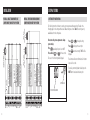
Wiring – single Transformer (use
Jumper Wire) for HEAT/COOL System
NOT USED
2nd HEATING
G
2nd COOLING
Y
NOT USED
W
OUTDOOR TEMP
SENSOR
COOLING
TRANSFORMER
2nd HEATING
2nd COOLING
G
NOT USED
Y
C S1 S2 O/B L W2 Y2
RC R
6
W
FAN
Y G
1st HEATING
W
1st COOLING
RC R
NOT USED
*Jumper between RC & R is used in single transformer systems
(see wiring diagrams).
OUTDOOR TEMP
SENSOR
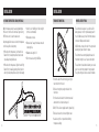
• Push the excess wire back into the opening and plug
the wall opening to prevent drafts.
FAN
• Loosen screw terminals, insert stripped wire and
re-tighten.
1st HEATING
• Ensure power at the HVAC equipment is off.
1st COOLING
Installation notes
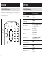
RC – 24 VAC supply cooling*
R – 24 VAC supply heating*
W – 1st stage heat / auxiliary
Y – 1st stage cooling / compressor
G – Fan
C – Common (optional when powered by batteries)
S1 & S2 – outdoor temperature sensor (optional)
O/B – Reversing valve
L – System fault indicator
W2 – 2nd stage heat / auxiliary
Y2 – 2nd stage cooling / compressor
JUMPER
18-24 gauge thermostat wire
TRANSFORMER
Wire specifications
Wiring – TWO TransformerS (REMOVE
Jumper Wire) for HEAT/COOL System
HEATING
TRANSFORMER
Installation
C S1 S2 O/B L W2 Y2
RC R
C S1 S2 O/B L W2 Y2
7