1
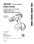
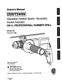
Owner's Manual
/
Adjustable Variable Speed - Reversible
Double Insulated
3/8 in. PROFESSIONAL
HAMMER DRILL
Model No.
315.277180
Save this manual for
future reference
_IL CAUTION:
Read and
follow all Safety Rules and
Operating Instructions before
first use of this product.
Sears,
Roebuck
972000-381
4-98
and Co., Hoffman
Estates,
IL 60179
USA
NRTL
•
Table Of Contents ..........................................................................................................................................
2
•
Warranty .........................................................................................................................................................
2
•
Introduction.....................................................................................................................................................
2
•
Rules For Safe Operation ...........................................................................................................................
•
Product Specifications ....................................................................................................................................
6
•
Unpacking .......................................................................................................................................................
6
•
Accessories ....................................................................................................................................................
6
•
Features .........................................................................................................................................................
7
•
Operation ...................................................................................................................................................
•
Maintenance .................................................................................................................................................
•
Exploded View and Repair Parts List ............................................................................................
•
Parts Ordering/Service
3-5
8-14
:.......: 16-17
...............................................................................................................................
FULL ONE YEAR WARRANTY ON CRAFTSMAN
15
18
PROFESSIONAL HAMMER DRILL
If this rRAFT$1qA# Hammer Drill fails due to a defect in material or workmanship within one year from the date
of purchase, Sears will repair it, free of charge.
WARRANTY SERVICE IS AVAILABLE BY SIMPLY RETURNING THE TOOL TO THE NEAREST SEARS
STORE IN THE UNITED STATES.
This warranty gives you specific legal rights, and you may also have other rights which vary from state to state.
Sears, Roebuck and Co., Dept. 817WA, Hoffman Estates, IL 60179
Your hammer drill has many features for making your
drilling operations more pleasant and enjoyable.
Safety, performance and dependability have been
given top priority in the design of this drill making it
easy to maintain and operate.
_
CAUTION: Carefully read through this entire
owner's manual before using your new hammer
drill. Pay close attention to the Rules For Safe
Operation, Warnings and Cautions. If you use
your drill properly and only for what it is intended,
you will enjoy years of safe, reliable service.
The purpose of safety symbols Is to attract your attention to possible dangers. The safety symbols, and
the explanations with them, deserve your careful attention and understanding. The safety warnings do
not by themselves eliminate any danger. The Instructions or warnings they give are not substitutes for
proper accident prevention measures.
SYMBOL
A
MEANING
SAFETY
ALERT
SYMBOL:
Indicates danger, waming, or caution. May be used in conjunction with other symbols or pictographs.
A
DANGER: Failure to obey a safety waming will result in serious injury to yourself or to others,
Always follow the safety precautions to reduce the dsk of fire, electdc shock and personal injury.
WARNING: Failure to obey a safety waming can result in serious injury to yourself or to others.
Always follow the safety precautions to reduce the dsk of fire, electdc shock and personal injury.
CAUTION: Failure to obey a safety waming may result in property damage or personal injuryto
yourself or to others. Always follow the safety precautions to reduce the dsk of fire, electdc shock
and personal injury.
NOTE:
DOUBLE
Advises you of information or instructionsvital to the operation or maintenance of the equipment.
INSULATION
Double insulation is a concept in safety, in electric
power tools which eliminates the need for the usual
three-wire grounded power cord. All exposed metal
parts are isolated from internal metal motor
components with protecting insulation. Double
insulated tools do not need to be grounded.
A
WARNING:
Do not attempt to operate this tool
until you have read thoroughly and understand
completely all instructions, safety rules, etc.
contained in this manual. Failure to comply can
result in accidents involving fire, electric shock,
or sedous personal injury. Save owner's manual
and review frequently for continuing safe
operation, and instructing others who may use
this tool.
READ ALL INSTRUCTIONS
Servicing of a tool with double insulation requires
extreme care and knowledge of the system and
should be performed only by a qualified service
technician. For service we suggest you return the tool
to your nearest Sears Store for repair. Always use
original factory replacement parts when servicing.
KEEP WORK AREA CLEAN. Cluttered areas
and benches invite accidents.
AVOID DANGEROUS ENVIRONMENT. Don't
use power tools in damp or wet locations or
expose to rain. Keep work area well lit.
KEEP CHILDREN AND VISITORS AWAY. All
visitors should wear safety glasses and be kept a
safe distance from work area. Do not let visitors
contact tool or extension cord.
KNOW YOUR POWER TOOL. Read owner's
STORE IDLE TOOLS. When not in use, tools
manual carefully. Learn its applications and
limitations as well as the specific potential
hazards rel-atedto this tool.
should be stored in a dry and high or locked-up
place - out of the reach of children.
GUARD AGAINST ELECTRICAL SHOCK by
preventing body contact with grounded surfaces.
For example; pipes, radiators, ranges, refrigerator enclosures.
B
IMPORTANT
KEEP GUARDS IN PLACE and in working
order.
DON'T FORCE TOOL. It will do the job better
and safer at the rate for which it was designed.
USE RIGHT TOOL. Don't force small tool or
attachment to do the job of a heavy duty tool.
Don't use tool for purpose not intended - for
example - A circular saw should never be used
for cutting tree limbs or logs.
RULES
FOR SAFE OPERATION
(Continued)
WEAR PROPER APPAREL. Do not wear loose
clothing or jewelry that can get caught in tool's
moving parts and cause personal injury. Rubber
gloves and nonskid footwear are recommended
when working outdoors. Wear protective hair
covering to contain long hair and keep it from
being drawn into nearby air vents.
MAKE SURE YOUR EXTENSION CORD IS IN
GOOD CONDITION. When using an extension
cord, be sure to use one heavy enough to carry
the current your product will draw. An undersized
cord will cause a drop in line voltage resulting in
loss of power and overheating, A wire gage size
(A,W.G.) of at least 16 is recommended for an
extension cord 100 feet or less in length. A cord
exceeding 100 feet is not recommended. If in
doubt, use the next heavier gage. The smaller
the gage number, the heavier the cord.
ALWAYS WEAR SAFETY GLASSES. Everyday
eyeglasses have only impact-resistant lenses;
they are NOT safety glasses.
PROTECT YOUR LUNGS. Wear a face or dust
OUTDOOR USE EXTENSION CORDS. When
mask if the operation is dusty.
PROTECT YOUR HEARING. Wear hearing
protection during extended periods of operation.
tool is used outdoors, use only extension cords
suitable for use outdoors. Outdoor approved
cords are marked with the suffix W-A, for example - SJTW-A or SJOW-A.
DON'T ABUSE CORD. Never carry tool by cord
or yank it to disconnect from receptacle. Keep
cord from heat, oil, and sharp edges.
KEEP BITS CLEAN AND SHARP, Sharp bits
minimize stalling and kickback.
KEEP HANDS AWAY FROM DRILLING AREA.
SECURE WORK. Use clamps or a vise to hold
work. It's safer than using your hand and it frees
both hands to operate tool.
Keep hands away from bits. Do not reach
underneath work while bit is rotating. Do not
attempt to remove material while bit is rotating.
DON'T OVERREACH. Keep proper footing and
balance at all times. Do not use on a ladder or
NEVER USE IN AN EXPLOSIVE ATMO-
unstable support. Secure tools when working at
elevated positions.
SPHERE. Normal sparking of the motor could
ignite fumes.
MAINTAIN TOOLS WITH CARE. Keep tools
sharp and clean for best and safest performance.
Follow instructionsfor lubdcating and changing
accessories.
damaged, have repaired by an authorized
service facility. Stay constantly aware of cord
location.
INSPECT TOOL CORDS PERIODICALLY and if
INSPECT EXTENSION CORDS PERIODI-
DISCONNECT TOOLS. When not in use, before
servicing, or when changing attachments,
blades, bits, cutters, etc., all tools should be
disconnected from power supply.
CALLY and replace if damaged.
KEEP HANDLES DRY, CLEAN, AND FREE
FROM OIL AND GREASE. Always use a clean
cloth when cleaning. Never use brake fluids,
gasoline, petroleum-based products, or any
strong solvents to clean your tool.
REMOVE ADJUSTING KEYS AND
WRENCHES. Form habit of checking to see that
keys and adjusting wrenches are removed from
chuck before turning tool on.
STAY ALERT AND EXERCISE CONTROL.
Watch what you are doing and use common
sense. Do not operate tool when you are tired.
Do not rush.
AVOID ACCIDENTAL STARTING. Don't carry
plugged-in tool with finger on switch. Be sure
switch is off when plugging in.
4
RULESFORSAFE OPERATION(Continued)
CHECKDAMAGED
PARTS.Beforefurtheruse
•
of the tool, a guard or other part that is damaged
should be carefully checked to determine that it
will operate properly and perform its intended
function. Check for alignment of moving pads,
binding-of moving parts, breakage of parts,
mounting and any other conditions that may
affect its operation. A guard or other part that is
damaged should be properly repaired or replaced by an authodzed service center.
before ddll!ng.
•
DRUGS, ALCOHOL, MEDICATION. Do not
operate this tool while under the influence of
drugs, alcohol, or any medication.
•
POLARIZED PLUGS. To reduce the dsk of
electdc shock, this tool has a polarized plug (one
blade is wider than the other). This plug will fit in
a poladzed outlet only one way. If the plug does
not fit fully in the outlet, reverse the plug. If it still
does not fit, contact a qualified electrician to
install the proper outlet. Do not change the plug
in any way.
DO NOT USE TOOL IF SWITCH DOES NOT
TURN IT ON AND OFF. Have defective switches
replaced by an authorized service center.
DRILLING INTO ELECTRICAL WIRING IN
WALLS CAN CAUSE DRILL BIT AND CHUCK
TO BECOME ELECTRICALLY LIVE. Do not
touch the chuck or metal housing when drilling
into a wall; grasp only the insulated handle(s)
provided on the tool.
_,
,_
Look for this symbol
safety is involved.
to point out important
INSPECT FOR and remove all nails from lumber
•
WHEN SERVICING USE ONLY IDENTICAL
CRAFTSMAN REPLACEMENT PARTS.
•
SAVE THESE INSTRUCTIONS. Refer to them
frequently and use them to instruct others who
may use this tool. If you loan someone this tool,
loan them these instructionsalso.
safety
precautions.
It means attention!!!
Your
WARNING:
The operation of any hammer ddll can result in foreign objects being thrown into your eyes,
which can result in severe eye damage. Before beginning power tool operation, always wear
safety goggles or safety glasses with side shields and a full face shield when needed. We
recommend Wide Vision Safety Mask for use over eyeglasses or standard safety glasses
with side shields, available at Sears Retail Stores.
SAVE THESE INSTRUCTIONS
5
Chuck
ChuckCapacity
Horsepower
Input
Rating
3/8in. Keyless Switch
Adjustable
Variable
Speed- Reversible
1/32in.to 318in. No Load Speed
0 - 1200 RPM
1/2 Hammer Speed
0 - 60,000 BPM
5.0Amperes Hammer Travel
.028
120volts,60Hz,AC
Your hammer drill has been shipped completely
assembled except for the auxiliary handle and depth
gage rod. Inspect it carefully to make sure no
breakage or damage has occurred during shipping. If
any pads are damaged or missing, contact your
nearest Sears Retail Store to obtain replacement pads
before attempting to operate hammer ddll. The
auxiliary handle, depth gage rod, and this owner's
manual are also included in the box.
_lb
WARNING: If any pads are missing, do not
operate this tool until the missing parts are
replaced. Failure to do so could result in possible
sedous personal injury.
The following recommended accessories are currently available at Sears Retail Stores.
•
High Speed Bits (For wood or metal)
3/8 in. Max.
•
Masonry Bits
1/2 in. Max.
•
Wood Boring Bits
1 in. Max.
•
Hole Saws
1 in. Max.
_k,
WARNING:
The use of attachments or accessories not listed might be hazardous.
6
KNOWYOURHAMMERDRILL
DEPTH GAGE
See Figure 1.
Before attempting to use any tool, familiarize yourself
with all operating features and safety requirements.
A depth gage rod has been packed with your hammer
ddll to assist you in controllingthe depth of drilled
holes.
ELECTRICAL
APPLICATIONS
CONNECTION
Your hammer ddll has a precision built electric motor.
It should be connected to a power supply that Is 120
volta, 60 Hz, AC only (normal household current).
Do not operate this tool on direct current (DC). A
substantial voltage drop will cause a loss of power
and the motor will overheat. If your hammer drill does
not operate when plugged into an outlet, doublecheck the power supply.
AUXILIARY
ROD
(Use only for the purposes listed below)
HANDLE
An auxiliary handle has been packed with your ddll for
ease of operation and to help prevent loss of control.
•
Hammer drilling in concrete and masonry.
•
Drilling in wood.
•
Drilling in ceramics, plastics, fiberglass, and
laminates.
•
Drilling in both hard and soft metals.
•
Using driving accessories, such as driving screws
with screwdriver bits.
•
Mixing paints.
DEPTHGAGEROD
KEYLESS
CHUCK
WING
SCREW
LOCK-ON
HAMMER
MODE
ADJUSTMENT
KNOB
VARIA
CONTROLSELECTOR
SWITCHTRIGGER
DRILLING
MODE
_1,
Fig. 1
WARNING: Do not allow familiarity with tools to make you careless. Remember that a careless fraction of
a second is sufficient to inflict severe injury.
7
am,
WARNING: Your drill should never be
connected to power supply when you are
assembling parts, making adjustments, installing
or removing ddll bits, cleaning, or when not in
use. Disconnecting your drill will prevent
accidental starting that could cause sedous
personal injury.
_lb WARNING: Before connecting your ddll to
power supply source, always check to be sure it
is not in lock-on position (depress and release
switch trigger). Failure to do so could result in
accidental starting of your ddll resulting in
possible sedous injury. Also, do not lock the
tdgger on jobs where your drill may need to be
stopped suddenly.
SWITCH
See Figure 2.
REVERSIBLE
To turn your hammer ddll ON, depress the switch
tdgger. Release switch trigger to turn your hammer
drill OFF.
See Figure 3,
SWITCH
TRIGGER
Your hammer ddll has the feature of being reversible.
The direction of chuck rotation is controlled by a lever
located above the switch trigger. With your ddll held in
normal operating position, the direction of rotation lever
should be positioned to the left of the switch for
forward ddlling operation. The direction of rotation is in
reverse when the lever is to the right of the switch.
The design of the switch will not permit changing the
direction of rotation while the ddll is running. Release
the switch tdgger and allow the drillto stop before
changing its direction.
Note: Your hammer ddll will not run unless the switch
lever is pushed fully to the left or dght.
LOCK-ON
REVERSE(R)
FORWARD(_
Fig. 2
LOCK-ON
BUTTON
See Figure 2.
Your hammer ddll is equipped with a lock-on feature,
which is convenient when continuous drilling for
extended pedods of time is required. To lock-on,
depress the switch trigger, push in and hold the lockon button located on the side of the handle, then
release switch trigger. Release lock-on button and
your drill will continue running.
FORWARD
REVERSELEVER
To release the lock, depress the switch trigger and
release.
If you have the lock-on feature engaged dudng use
and your drill becomes disconnected from power
supply, disengage the lock-on feature immediately.
8
Fig. 3
VARIABLESPEED
The following guidelines may be used in determining
correct speed for various applications:
See Figure 4.
Your hammer ddll has a variable speed control
selector designed to allow operator control and
adjustment of speed and torque limits. Speed and
torque can be increased or decreased by rotating the
variable speed control selector in the direction of the
arrows shown in figure 4.
Low speed is ideal when minimum speed and power
is required. For example: starting holes without center
punching, driving screws, mixing paint, and drilling in
ceramics.
VARIABLESPEED
CONTROLSELECTOR
High speed produces best results when maximum
power is required. For example: drilling in wood; soft
metals such as aluminum, brass, and copper;
concrete; and when using driving accessories.
Medium speed is suitable for drilling hard metals,
plastics, and laminates.
KEYLESS CHUCK
See Figure 5.
SPEED(+)
Your new drill has a keyless chuck. As the name
implies, you can hand tighten or release ddll bit in the
chuck jaws. Grasp and hold the collar of the chuck
with one hand. Rotate the chuck body with your other
hand. The arrows shown in figure 5 indicate which
direction to rotate the chuck body in order to GRIP
(tighten) or RELEASE (unlock) the drill bit.
TODECREASE
SPEED(-)
RELEASE
(UNLOCK)
Fig, 4
CHUCKBODY
DRILLBIT
Note: Hold your hammer drill in normal operating
position and turn the variable speed control selector
clockwise to increase (+) the speed and torque of
your hammer drill. Turn counterclockwise to decrease
(-) the speed and torque of your hammer drill.
If you desire to lock the switch on at a given speed,
depress the switch trigger, push in and hold the lockon button, and release the switch trigger. Next, adjust
the variable speed control selector until the desired
speed is reached.
GRIP
Note: If the variable speed control selector is fully
turned in the counterclockwise direction, (zero setting)
your drill may not run.
(TIGHTEN) CHUCKCOLLAR
Fig. 5
If you desire not to use the variable speed control
selector, turn it in the full clockwise direction. This
will allow the speed of your drill to be fully
controlled by the amount of switch trigger
depression,
,_
Avoid running your hammer drillat low speeds for
" _xt-ended periods of time. Running at low speeds
under constant usage may cause your drill to become
overheated. If this occurs, cool your drill by running it
without a load and at full speed.
9
WARNING: Do not hold chuck body with one
hand and use power of the drill to tighten chuck
jaws on drill bit. Chuck body could slip in your
hand or your hand could slip and come in contact
with rotating drill bit. This could cause an
accident resulting in serious personal injury.
/
INSTALLINGAUXILIARYHANDLE
TO INSTALL
See Figure 6.
See Figure 7.
An auxiliary handle is packed with your ddll for ease
of operation and to help prevent loss of control.
The handle c-anbe rotated 360 ° and it can also be
mounted on opposite side for left hand use.
Note: For convenience and ease of starting threads,
the hex nut has been trapped inside the molded slot in
the auxiliary handle,
•
•
_
•
injury.
•
Loosen wing screw enough to make opening in
handle large enough to fit over chuck.
•
Slide dng of handle over chuck. Note: Handle fits
on neck of gear housing.
Rotate handle to desired operating position
aligning notches in handle with tabs on gear
housing.
•
•
•
Open or close the chuck jaws to a point where the
opening is slightly larger than the drill bit you
intend to use. Also, n_ise the front of your drill
slightly to keep the drill bit from falling out of the
chuck jaws.
Insert ddll bit into chuck the full length of the jaws.
•
Tighten chuck jaws on drill bit.
DRILLBIT
CHUCKJAWS
Tighten wing screw securely.
Note: If wing screw and wear plate is removed
from auxiliary handle, when reassembling, the
markings on the wear plate must be positioned as
shown in figure 6. This prevents the depth gage
rod from slipping. See Figure 9.
KEYLESSCHUCK
RIGHT
KEYLESSCHUCK
MARKINGSON
WEARPLATE
WING
SCREW
Fig. 7
•
To tLghtenthe chuck jaws on drill bit; grasp and
hold the collar of the chuck with one hand, while
rotating the chuck body with your other hand.
Note: Rotate the chuck body in the direction of
the arrow marked GRIP to tighten chuck jaws.
•
Do not use a wrench to tighten or loosen the
chuck jaws.
_1= WARNING: Do not insert drill bit into chuck
jaws and tighten as shown in figure 8. This could
cause ddll bit to be thrown from your drill
resulting in possible serious personal injury or
damage to your chuck.
TABS
TIGHTEN
WARNING:
Failure to unplug your hammer ddll
could result in accidental starting causing sedous
injury.
WARNING: Failure to unplug your hammer ddll
could result in accidental starting causing sedous
Remove auxiliary handle from plastic bag.
Unplug your hammer ddll.
,_
Unplug your hammer drill.
•
BITS
\
LOOSEN
NOTCHES
AUXILIARY
HANDLE
Fig. 6
To prevent possible loss of control, auxiliary handle
should be checked periodically for tightness. Do not
operate hammer drill with auxiliary handle loose.
Fig. 8
10
REMOVING BITS
•
When ddlling holes with the depth gage rod installed,
the desired hole depth has been reached when the
end of the rod comes in contact with the surface of the
Unplugyourhammerdrill.
material being drilled.
_1= WARNING: Failure to unplug your hammer ddll
could result in accidental starting causing serious
TO ADJUST
injury.
MODE
See Figure 10.
•
Loosen the chuck jaws from drill bit.
•
To loosen: grasp and hold the oollar of the chuck
with one hand, while rotating chuck body with your
other hand.
Note: Rotate chuck body in the direction of the
arrow marked RELEASE to loosen chuck jaws.
•
Do not use a wrench to tighten or loosen the
chuck jaws.
Remove drill bit from chuck jaws.
•
DRILLING
USING DEPTH
To adjust for desired type of drilling, rotate adjustment
knob on side of motor housing in the direction of
arrows as shown in figure 10. For your convenience a
hammer symbol and drill bit symbol have been
molded into adjustment knob.
_k
WARNING: Your hammer drill has not been
designed for reverse hammering. Reverse
hammering may damage your drill.
ADJUSTMENTKNOB
GAGE ROD
HAMMERMODE
See Figure 9.
A depth gage rod has been packed with your hammer
ddll to assist you in controlling the depth of drilled
holes.
•
Loosen wing screw on auxiliary handle.
•
Orient depth gage rod so that markings on depth
gage red face markings on wear plate. Insert
depth gage rod through hole on auxiliary handle.
•
Adjust depth gage rod so that the drill bit extends
beyond the end of the rod to the required drilling
depth.
Tighten wing screw securely. This secures depth
gage rod at desired depth of cut. It also secures
auxiliary handle.
•
MARKINGSON
DEPTHGAGEROD
TO
TO
INCREASE
DECREASE DRILUNG
DRILUNG
DEPTH
DEPTH
|
DRILUNGMODE
Fig. 10
WEAR
WING
PLATE
We recommend that you use carbide-tipped bits and
select hammer mode when drilling in hard materials
such as brick, tile, concrete, etc.
_1_ ScREw
We recommend that you select normal ddll mode
when drilling with twist drills, hole saws, etc. in soft
materials.
DEPTH
GAGEROD
DRILLBIT
DRILLINGDEPTH
AUXIUARYHANDLE
Fig. 9
11
DRILLING
•
Secure the material to be drilled in a vise or with
clamps to keep it from turning as the drillbit
rotates.
•
Plug your drill into power supply source.
•
Hold your drill firmly and place the bit at the point
to be drilled.
•
Depress the switch trigger to start your drill. Do not
lock the switch on for jobs where your drill may
need to be stopped suddenly.
•
Move the drillbit intoworkpiece applying only
enough pressure to keep the bit cutting. Do not
force your drill or apply side pressum to elongate a
hole. Let your drill and bit do the work.
See Figure 11.
j
When drilling hard smooth surfaces use a center
punch to mark desired hole location. This will prevent
the drill bit from slipping off center as the hole is
started. However, the variable speed feature allows
starting holes without center punching if desired. To
accomplish this, simply operate your drill at a low
speed until the hole is started.
,_
When drilling metals, use a light oil on the drill bit to
keep it from overheating. The oil will prolongthe life of
the bit and increase the drilling action.
Fig. 11
•
•
WARNING: Be prepared for binding or bit
breakthrough. When these situations occur, drill
has a tendency to grab and kick opposite to the
direction of rotation and could cause loss of
control when breaking through material. If not
prepared, this loss of control can result in
possible serious injury.
Depress and release the switch trigger to be sure
your drill is in off position before connecting it to
power supply.
Check the direction of rotation lever for correct
setting (forward or reveme). See Figure 3.
If the bit jams in workpiece or if the drill stalls, stop the
tool immediately. Remove the bit from the workpiece
and determine the mason for jamming.
12
WOOD
DRILLING
•
For maximum performance, use high speed steel
bits for wood ddlling.
•
Turn adjustment knob on hammer drill to normal
ddlnng action.
•
Begin ddlling at a very low speed to prevent the bit
from slippingoff the starting point. Increase the
speed as the ddll bit bites intothe matadal.
•
When ddllingthrough holes, place a block of wood
behind the workpiece to prevent ragged or
splintered edges on the back side of the hole.
•
Do not lock the trigger on for Jobs where your
hammer drill may need to be stopped
suddenly.
METAL
MASONRY
•
For maximum performance, use high speed steel
bits for metal or steel ddlllng.
•
Turn adjustment knob on hammer ddUto normal
ddUingaction.
•
Begin ddlling at a very low speed to prevent the bit
from slippingoff the starting point.
•
Maintain a speed and pressure which allows
cutting without overheating the bit. Applyingtoo
much pressure will:
Overheat the ddll;
•
Apply light pressure and medium speed for best
results in brick.
•
Apply additional pressure and high speed for hard
matedals such as concrete.
•
When ddlling holes in tile, practice on a scrap
piece to determine the best speed and pressure.
POWER
CORD
See Figure 12.
Your new hammer ddll has a 10 ft. power cord that
stays soft and flexible in cold weather. The plug
design is shaped so that it won't snag on your work
dudng use. A molded cord clip on the plug makes
cord storage easier.
MOLDEDCORDCUP
Wear the bearings;
Bend or bum bits; and
lOFT. CORD
Produce off-center or irregular shaped holes.
•
For maximum performance use carbide*tipped
masonry impact bits when ddlling holes in
bdck, tile, concrete, etc.
•Tum
adjustment knob on hammer ddll to
hammer mode.
DRILLING
•
DRILLING
When ddlling large holes in metal, we recommend
that you ddUwith a small bit at first, then finish with
a larger bit. Also, lubdcate the bit with oil to
improve ddlling action and increase bit life.
Fig. 12
13
CHUCK
REMOVAL
•
See Figures 13, 14, and 15.
The chuck must be removed in order to use some
accessories. To remove:
•
Insert hex key wrench into chuck and tighten
chuck jaws securely. Tap sharply with a mallet
in a counterclockwise direction. This will loosen
chuck on the spindle. It can now be unscrewed
by hand. See Figure 15.
Unplug your hammer drill.
_k
WARNING: Failure to unplug your hammer ddll
could result in accidental starting causing sedous
injury.
Line up hole in spindle with slot in gear housing
and insert a 118 in. diameter nail or pin in
spindle shaft.
•
Insert a 5/16 in. or larger hex key wrench (allen
wrench) into the chuck of your drill and tighten
the chuck jaws securely.
•
Tap the hex key sharply with a mallet in a
clockwise direction. See Figure 13. This will
loosen the screw in the chuck for easy removal.
Fig. 15
•
1/8In. DIAMETER
)R PIN
MALLET
Unlock spindle by removing nail or pin from slot
in gear housing.
TO RETIGHTEN
A LOOSE CHUCK
The chuck may at times become loose on the spindle
and develop a wobble. Also, the chuck screw may
become loose causing the chuck jaws to bind and
prevent them from closing. To tighten, follow these
steps:
•
WARNING: Failure to unplug your hammer drill
could result in accidental starting causing serious
injury.
KEYLESS
CHUCK
HEXKEY
WRENCH
Fig. 13
•
Open chuck jaws and remove heX"key wrench.
•
Remove the chuck screw by turning it in a
clockwise direction. See Figure 14. Note: The
screw has left hand threads.
Unplug your hammer drill.
Line up hole in spindle with slot in gear housing
and insert a 118 in. diameter nail or pin in
spindle shaft.
Insert hex key wrench into chuck and tighten
chuck jaws securely, Tap hex key wrench sharply
with a mallet in a clockwise direction. This will
tighten chuck on the spindle.
Open the chuck jaws and remove hex key
wrench.
Tighten
has left
Unlock
in gear
SCREWDRIVER
!
Fig. 14
14
the chuck screw. Note: The chuck screw
hand threads.
spindle by removing nail or pin from slot
housing.
_i
WARNING: Always wear safety goggles or
safety glasses with side shields during power tool
operation or when blowing dust. If operation is
dusty, also wear a dust mask.
WARNING: When servicing, use only identical
Craftsman replacement pads. Use of any other
part may create a hazard or cause product
damage,_
GENERAL
LUBRICATION
Only the parts shown on parts list, page seventeen,
are intended to be repaired or replaced by the
customer. All other parts represent an important part
of the double insulation system and should be
serviced only by a qualified Sears service technician.
All of the bearings in this tool are lubricated with a
sufficient amount of high grade lubricant for the life of
the unit under normal operating conditions. Therefore,
no further lubrication is required.
Avoid using solvents when cleaning plastic parts.
Most plastics are susceptible to damage from various
types of commemial solvents and may be damaged
by their use. Use clean cloths to remove dirt, carbon
dust, etc.
The use of any extension cord will cause some loss of
power. To keep the loss to a minimum and to prevent
tool overheating, use an extension cord that is heavy
enough to carry the current the tool will draw.
EXTENSION
CORDS
A wire gage size (A.W.G.) of at least 16 is
recommended for an extension cord 100 feet or less
in length. When working outdoors, use an extension
cord that is suitable for outdoor use. The cord's jacket
will be marked WA.
WARNING: Do not at any time let brake fluids,
gasoline, petroleum-based products, penetrating
oils, etc. come in contact with plastic parts. They
contain chemicals that can damage, weaken or
destroy plastic.
_k
It has been found that electdc tools are subject to
accelerated wear and possible premature failure when
they are used on fiberglass boats, sports cars,
wallboard, spackling compounds, or plaster. The
chips and grindings from these materials are highly
abrasive to electric tool parts such as bearings,
brushes, commutators, etc. Consequently, it is not
recommended that this tool be used for extended
work on any fiberglass material, wallboard, spackling
compounds, or plaster. During any use on these
materials it is extremely important that the tool is
cleaned frequently by blowing with an air jet.
CAUTION: Keep extension cords away from the
ddUing area and position the cord so that it will
not get caught on lumber, tools, etc., during
drilling operation.
WARNING: Check extension cords before each
use. If damaged, replace immediately. Never use
tool with a damaged cord since touching the
damaged area could cause electrical shock
resulting in serious injury.
Extension cords suitable for use with your hammer drill
are available at your nearest Sears Retail Store.
15
CRAFTSMAN
3/8 in. HAMMER
DRILL -- MODEL NUMBER
315.277180
SEE NOTE "A" PAGE 17
2
7
3
6
16
CRAFTSMAN
318 in. HAMMER
DRILL m MODEL NO. 315.277180
The model number will be found on a plate attached to the motor housing. Always mention the model number in all correspondence regarding your
3/8 in. HAMMER DRILL or when ordering repair parts.
SEE BACK PAGE FOR PARTS ORDERING
INSTRUCTIONS
PARTS LIST
Key No.
Pad No.
Description
Quan.
1
616478-002
2
973754-002
3
975104-001
Data Plate ............................................................................................................
1
4
975103-001
Logo Plate ..............................
1
5
975250-001
Auxiliary Handle ..................................................................................................
1
6
975113-001
7
975253-001
Depth Gage Rod .................................................................................................
Wear Plate ...........................................................................................................
1
1
8
975252-001
Wing Screw (M6 x 40 mm) ..................................................................................
1
972000-381
Owner's Manual
* Screw (#12-28 x 0.9 in. Fil. Hd., Left Hano) ........................................................
Chuck ................................................................................................................
.. ...........................................................................
1
1
NOTE: "A"--The assembly shown represents an important part of the Double Insulated System.To,avoid the possibility of altersUon or damage
to the system, service should be performed by your nearest Sears Repair Center. Contact your nearest Sears Retail Store for Service Center
information.
* Standard Hardware Item m May Be Purchased Locally.
17
Forthe repairor replacementpartsyouneed
delivereddirectlytoyourhome
Call7 am - 7 pro,7 daysa week
1-800-366-PART
(1-800-366-7278)
Forrepairservice
Call24 hoursa day,7 daysa week
1-8OO-4-REPAIR
(1-800-473-7247)
Forthe locationofa
SearsPartsandRepairCenterin yourarea
Call24 hours a day,7 daysa week
1-800-488-1222
Themodelnumberofthis toolwill befoundona serial plate
attachedto the motorhousing.Whenrequestingserviceor
oi;d-eHng
parts,always providethe followinginformation:
• ProductName
3/8 in. Professional
HammerDrill
• ModelNumber
315.277180
• Part Name
• PartNumber
SEARS
America's
FtepairSpecia/ists